EP1816415A2 - Refrigerating system using "free energy" for circulating liquid re-frigerant by pressure - Google Patents
Refrigerating system using "free energy" for circulating liquid re-frigerant by pressure Download PDFInfo
- Publication number
- EP1816415A2 EP1816415A2 EP07002617A EP07002617A EP1816415A2 EP 1816415 A2 EP1816415 A2 EP 1816415A2 EP 07002617 A EP07002617 A EP 07002617A EP 07002617 A EP07002617 A EP 07002617A EP 1816415 A2 EP1816415 A2 EP 1816415A2
- Authority
- EP
- European Patent Office
- Prior art keywords
- refrigerant
- refrigerating system
- heat exchanger
- pumping
- primary
- Prior art date
- Legal status (The legal status is an assumption and is not a legal conclusion. Google has not performed a legal analysis and makes no representation as to the accuracy of the status listed.)
- Withdrawn
Links
- 239000007788 liquid Substances 0.000 title claims description 53
- 239000003507 refrigerant Substances 0.000 claims abstract description 120
- 238000005086 pumping Methods 0.000 claims abstract description 61
- 238000001704 evaporation Methods 0.000 claims abstract description 22
- 230000008020 evaporation Effects 0.000 claims abstract description 8
- 230000009467 reduction Effects 0.000 claims abstract description 6
- 238000010438 heat treatment Methods 0.000 claims description 21
- 230000005484 gravity Effects 0.000 claims description 8
- 238000000034 method Methods 0.000 claims description 7
- 239000002699 waste material Substances 0.000 claims description 2
- 238000001816 cooling Methods 0.000 abstract description 15
- 238000005265 energy consumption Methods 0.000 abstract description 5
- XLYOFNOQVPJJNP-UHFFFAOYSA-N water Substances O XLYOFNOQVPJJNP-UHFFFAOYSA-N 0.000 abstract description 2
- CURLTUGMZLYLDI-UHFFFAOYSA-N Carbon dioxide Chemical compound O=C=O CURLTUGMZLYLDI-UHFFFAOYSA-N 0.000 description 16
- 229910002092 carbon dioxide Inorganic materials 0.000 description 8
- 238000005057 refrigeration Methods 0.000 description 8
- 239000001569 carbon dioxide Substances 0.000 description 7
- QGZKDVFQNNGYKY-UHFFFAOYSA-N Ammonia Chemical compound N QGZKDVFQNNGYKY-UHFFFAOYSA-N 0.000 description 6
- 230000007935 neutral effect Effects 0.000 description 5
- 238000009833 condensation Methods 0.000 description 4
- 230000005494 condensation Effects 0.000 description 4
- 238000012423 maintenance Methods 0.000 description 4
- 229910021529 ammonia Inorganic materials 0.000 description 3
- 239000002826 coolant Substances 0.000 description 3
- 230000007246 mechanism Effects 0.000 description 3
- 239000003921 oil Substances 0.000 description 3
- 238000012546 transfer Methods 0.000 description 3
- 238000007664 blowing Methods 0.000 description 2
- 230000008859 change Effects 0.000 description 2
- 230000009471 action Effects 0.000 description 1
- 239000003990 capacitor Substances 0.000 description 1
- 239000010725 compressor oil Substances 0.000 description 1
- 230000001276 controlling effect Effects 0.000 description 1
- 238000009434 installation Methods 0.000 description 1
- 239000000463 material Substances 0.000 description 1
- 238000012806 monitoring device Methods 0.000 description 1
- 230000008569 process Effects 0.000 description 1
- 238000011084 recovery Methods 0.000 description 1
- 230000001105 regulatory effect Effects 0.000 description 1
- 238000000926 separation method Methods 0.000 description 1
- 238000009491 slugging Methods 0.000 description 1
- 239000000126 substance Substances 0.000 description 1
- 238000013022 venting Methods 0.000 description 1
Images


Classifications
-
- F—MECHANICAL ENGINEERING; LIGHTING; HEATING; WEAPONS; BLASTING
- F25—REFRIGERATION OR COOLING; COMBINED HEATING AND REFRIGERATION SYSTEMS; HEAT PUMP SYSTEMS; MANUFACTURE OR STORAGE OF ICE; LIQUEFACTION SOLIDIFICATION OF GASES
- F25B—REFRIGERATION MACHINES, PLANTS OR SYSTEMS; COMBINED HEATING AND REFRIGERATION SYSTEMS; HEAT PUMP SYSTEMS
- F25B25/00—Machines, plants or systems, using a combination of modes of operation covered by two or more of the groups F25B1/00 - F25B23/00
- F25B25/005—Machines, plants or systems, using a combination of modes of operation covered by two or more of the groups F25B1/00 - F25B23/00 using primary and secondary systems
Definitions
- the invention relates to a cascade refrigerating system comprising a primary refrigerating system operating with a first refrigerant, which primary refrigerating system comprises compressor means connected to condensing means, where the primary refrigerating system further comprises heat exchanging means, where heat is exchanged from a secondary refrigerating system, which secondary refrigerating system comprises pumping means arranged to supply refrigerant to evaporating means and where the secondary refrigerating system comprises at least two pumping vessels connected through respective check valves, which pumping vessels are connected to at least one heat exchanger, in which refrigerant is evaporated to generate a high pressure, which high pressure is led to the top of one of the pumping vessels to supply refrigerant to the evaporation means.
- GB 1,146,428 describes improvements in a flooded coil refrigerating system, where tanks are designed to collect a re-circulating excess refrigerant from the evaporators to eliminate slugging of the compressor.
- the driving force of the prior art system is the pressure difference between the compressor discharge or condenser pressure and the suction pressure of the compressor, which is similar to most other refrigerating systems.
- one of the receivers is connected to the condenser, and liquid refrigerant fills the first receiver, which at the same time is connected through restriction means to flooded evaporators, from which refrigerant is led to the second receiver, where liquid remains and gas is led to the suction side of the compressor.
- valves are opened and closed to change the operation of the receivers.
- DE 3511421 A1 describes a refrigeration circuit, which comprises adjustable means to increase the pressure in the refrigeration circuit with a low condensation temperature. This way it is possible to fulfil condensation by using very low refrigerant temperatures with a very low condensation pressure without experiencing circulation problems.
- the system relates to energy savings by means of low condensing temperatures, which maintains sufficient refrigerant pressure for the expansion valve.
- EP 1 046 868 A2 describes a refrigerating system having a refrigeration cycle, which provides optimised energy consumption.
- Prior art discloses the use of the gravity force for generating flow of the refrigerant. Gravity force systems can be difficult to install on site due to physical restrictions regarding the installation of components and the piping in buildings.
- EP 1536190 A1 concerns a cascade refrigerating system comprising a first high temperature refrigerating system operating with a first refrigerant, where the first high temperature system comprises heat exchanging means, where heat is exchanged from a second low temperature refrigerating system.
- the second low temperature refrigerating system comprises pumping means arranged to supply refrigerant to evaporating means.
- the second low temperature refrigerating system may comprise at least two pumping vessels connected through respective check valves, which pumping vessels are connected to heating means in which refrigerant is evaporated to generate high pressure, which high pressure is led to the top of the pumping vessels to press refrigerant towards the evaporation means.
- liquid refrigerant evaporates and generates pressure in the related vessel as it is exposed to the heating means. This way the circulation system is able to operate with refrigerant completely without oil, since the system does not include any compressors or pumps. This leads to improved performance and improved heat transfer.
- JP 2002048422 describes a natural circulation type heat pumping system comprising a cascade condenser, an ammonia refrigerant system, a carbon dioxide refrigerant system, hence a carbon dioxide gas generated by the carbon dioxide refrigerating system is guided to the capacitors 3 and heat exchanged with an ammonia liquid of the ammonia refrigerant system.
- the system furthermore comprises pressure tanks for containing liquefied carbon dioxide from the condensers 3 to heat the liquefied carbon dioxide via heat exchangers and to increase the pressure inside the tanks; the liquefied carbon dioxide is lifted to a serge tank installed above the evaporator of the carbon dioxide refrigerating system.
- a high level serge tank 6 is necessary to secure continued flow to evaporator means.
- JP 11 132507 describes a refrigerating system with improved reliability of refrigerant circulation by means of a reduction of the number of trouble occurring factor spots by means of a method according to which there is a need for a valve mechanism to switch pressurization through evaporation of a refrigerant.
- the pressure reduction is eliminated from a device formed to generate a circulation drive force for refrigerant in a circuit by utilizing a pressure generated through heating and cooling of a refrigerant.
- a drive force generating circuit having a liquid receiver is connected to a liquid line of a refrigerant circuit B on the utilization side of a secondary refrigerant system.
- a refrigerating device comprises a heater to generate high pressure through evaporation of a refrigerant by heating the pressurized heat-exchanger and a cooler to generate low pressure through condensation of a refrigerant by cooling a pressure-reduced heat-exchanger.
- Regulating the heating amount of the heater and the cooling amount of the cooler alternately generates a state to generate high pressure in the liquid receiver, and a state wherein low pressure is exerted, hence discharge of liquid from the liquid receiver, and recovery of liquid to the liquid receiver is alternately affected.
- EP 0857936 B1 concerns a heat exchanger on a secondary heat source exchanging heat with a heat exchanger on the primary heat source in a primary cooling circuit, and which is connected to an indoor heat exchanger through a gas pipe and a liquid pipe.
- a tank storing a liquid cooling medium is connected at its lower end to the liquid pipe and at its upper end to a pressure adjustment mechanism.
- Check valves are disposed on both sides of the connecting portion of the tank having regard to the liquid pipe.
- the internal pressure of the tank is either high or low and the state of the pressure changes by means of the pressure adjustment mechanism, thus the liquid cooling medium is supplied to the indoor heat exchanger, when the pressure is high, and the liquid cooling medium is recovered from the heat exchanger on the secondary side of the tank and is circulated by a secondary cooling circuit during low pressure.
- JP 11 023079 concerns a method according to which a natural refrigerant is used in a circulation cycle on the secondary side, a booster is arranged in a position below primary and secondary heat-exchanging parts, and a solenoid valve is arranged on the outlet side of a boosting device.
- a secondary refrigerant being a natural refrigerant such as CO2, which is radiated and condensed by a refrigerator 1 on the primary side, is fed to a heat-exchanger 2 on the secondary side by the absorbing of heat, and a substance to be cooled is cooled.
- a secondary refrigerant evaporated by the heat-exchanger on the secondary side is returned to the refrigerator on the primary side, and by means of its own weight it drops into a liquid reservoir situated downstream from the condensing part of the refrigerator on the primary side, and the refrigerant is stored therein.
- a secondary refrigerant in the liquid reservoir is supplied by means of its own weight to a booster through a check valve. When a liquid refrigerant is sufficiently stored in a booster, solenoid valves are closed.
- a secondary refrigerant is heated by a heating device to increase the internal pressure of the booster, and the secondary refrigerant is fed to a heat-exchanger on the secondary side through a piping on the secondary side.
- the present application does not describe any pressure equalization in the tanks when alternating between tanks.
- the purpose of the invention is to provide an energy efficient refrigerating system suitable for refrigerant circulation with reduced energy consumption for the circulation of refrigerant in refrigerating systems.
- the energy for generating pressure in the secondary refrigerating system is removed from the first refrigerating system, making this application energy neutral.
- the secondary liquid refrigerant When the secondary liquid refrigerant is exposed to heat in the heat exchanger, it evaporates and generates pressure in the related vessel. This way the circulation system can operate with refrigerant completely without oil since the system does not include any compressors or pumps. This leads to better performance and better heat transfer.
- the heat exchanger has an inlet for the second refrigerant, which is connected to the lower part of the pumping vessels, where the heat exchanger has an outlet connected to the upper part of the pumping vessels. It is hereby achieved that liquid secondary refrigerant is supplied by gravity from at least one of two pumping vessels to a related heat exchanger located in the same level as the lower part of the pumping vessels.
- the refrigerant is injected into one or more heat exchangers where the pressurized gas is produced by evaporating the second refrigerant. This way a pressure difference is provided, which pressure difference has enough force to press refrigerant through the refrigerating system.
- the pressurized gas produced by the evaporating secondary refrigerant is supplied into the vessel acting as high pressure.
- the high pressure of the contained liquid refrigerant makes the liquid refrigerant flow through non-return valves into the liquid line.
- a control circuit makes the sequence alter so the second vessel supplies liquid and the first vessel fill up.
- the upper part of the pumping vessels can be connected through a line, which line contains solenoid valves towards the vessels from where the line is further connected to the return line from the evaporators through a solenoid valve.
- a line which line contains solenoid valves towards the vessels from where the line is further connected to the return line from the evaporators through a solenoid valve.
- a common heat exchanger may comprise a first section, which first section is connected to the permanent open line, where a second and third section of the common heat exchanger is connected to the pumping vessels.
- control can be performed by small and less expensive solenoids valves.
- the material of the heat exchanger is always pre-heated by the primary refrigerant, ensuring a quick heating action.
- first and a second heat exchanger is serially coupled and connected to the permanent open line.
- standard heat exchangers may be used as long as a mostly unrestricted flow of the first refrigerant is achieved through the serially coupled heat exchangers.
- the invention further relates to a method for operating a refrigerating system with free energy, which refrigerating system can be operated by at least two pumping means to supply refrigerant to evaporating means through expansion means, where the refrigerant flows from the evaporators through condensing means, from where the refrigerant flows back towards the pumping means, which pumping means can be pressurized by evaporating refrigerant in at least one heat exchanger for supplying refrigerant at high pressure towards the evaporation means, where the heat exchanger can be heated primarily by free energy flowing towards and away from the heat exchanger through permanent open lines.
- Free energy can be achieved by connecting the heat exchanger to refrigerant flowing to or from a condensing means operating with sufficient high temperature.
- the heating energy for generating pumping pressure of the secondary refrigerant is removed from the primary refrigerating system, which makes the circulation system work with "free energy" without any external energy source.
- Free energy for generating pumping pressure of the secondary refrigerant can be achieved by connecting the heat exchanger to refrigerant flowing to or from a condensing means operating with sufficient high temperature.
- the heating energy for generating pumping pressure of the secondary refrigerant is removed from the primary refrigerating system, which makes the circulation system work with "free energy” without any external energy source.
- Free energy for generating pumping pressure of the secondary refrigerant can be achieved by superheating the suction gas from the evaporating means or from additional superheating means, which makes the circulation system work with “free energy” from the cooling load without any external energy source.
- Additional heating means can be added, if there is not sufficient superheated gas available.
- heating energy for generating pumping pressure of the secondary refrigerant can be achieved by heating the heat exchanger by any (waste) energy flowing in a liquid or gaseous media through lines to and from the heat exchanger.
- the described systems can provide pressurized circulation of the secondary refrigerant of rotating parts in pumps or compressors and the refrigerating system requires limited regular maintenance.
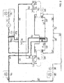
- fig. 1 shows an embodiment of the invention comprising compressor means
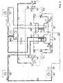
- fig. 2 shows an alternative embodiment of the invention
- fig. 3 describes a third embodiment of the invention
- fig. 4 shows an alternative embodiment of the invention.
- Fig. 1 shows a first cascade refrigerating system, where the cascade heat exchanger 2 is cooled by a primary refrigerating system 4.
- the primary refrigerating system 4 can be any suitable system using any suitable refrigerant.
- the heat exchanger 2 functions as the cascade condenser of the secondary refrigerating system. Liquid flows through the pipe 9 and alternates further through the pipe 8 or 10, which leads to non-return valves 12 or 14 and through the pipe 16 or 18 into the pumping vessels 20 or 22.
- the outlet of the pumping vessels 20 or 22 are connected through pipe 24 or 26, through non-return valves 28 or 30 into the liquid line 32, which leads to flow restriction means 34, which restriction means might be electronically controlled expansion valves.
- the restriction means 34 the secondary refrigerant is led to evaporators 40.
- the outlet pipes 52 from the evaporator 40 are led to the cascade condenser 2.
- a part stream of the liquid secondary refrigerant is led from the pumping vessels 20 or 22 through magnetic valves 120 and 122 and into the pipe 60 or 62 into one of the sections of a common heat exchanger 67, where liquid secondary refrigerant is evaporated when exposed to a heat source.
- the evaporated refrigerant gas is led back to the related vessels 20, 22 through the pipes 68, 70 generating pressure for the operation of the system.
- the common heat exchanger is heated by liquid primary refrigerant.
- the entire liquid primary refrigerant leaves the cascade condenser through line 100 and is led to the central section of the common heat exchanger 67 from which the now subcooled primary refrigerant flows through line 106 towards the cascade expansion valve 112.
- the vessel 20, 22 will in loading mode equalize pressure through pipe 72, 74, onto the solenoid valves 76, 78, through the pipes 80, 82, 84 into the common return line 52 or 44.
- the vessel 20 operates at high pressure when supplying liquid and the vessel 22 operates at low pressure when loading liquid.
- the solenoid valve 76 is closed and the liquid is trapped inside the HP vessel 20. Due to the high pressure, the inlet non-return valve 12 is closed and the outlet non-return valve 28 is open. By opening the solenoid valve 120, the trapped liquid is heated/evaporated by the heat exchanger 67, generating high pressure.
- the solenoid valve 78 and 79 are open so the pressure of vessel 22 is equalized to the condenser 2 and the liquid is drained by gravity from the condenser 2 through non-return valve 14 to vessel 22.
- the HP vessel (20) is empty, the system alternates.
- the system is controlled by a monitoring device 21, 23 or by means of a timer (not shown).
- the solenoid valve 79 in the common venting line 84 closes both the solenoid valves 76 and 78 equalizing the pressure between vessel 20 and 22.
- the solenoid valve 78 closes, solenoid valves 76 and 79 opens and vessel 22 is now in operation as HP vessel supplying liquid.
- the solenoid valve 76 and 79 are open so the pressure of vessel 20 is equalized to the condenser 2 and the liquid is drained by gravity from the condenser 2 through non-return valve 12 to vessel 20.
- the HP vessel (22) is empty, the system alternates again.
- the system can operate by changing between an active (supplying) and an inactive (loading) vessel during the entire operation.
- Fig. 2 shows an alternative embodiment of the invention. Most of the functions of the second refrigerating system are equal to those shown in fig. 1, thus they will not be mentioned. The only differences between fig. 1 and 2 will be mentioned in the following.
- the major difference is that the common heat exchanger 48 in fig. 2 is connected differently than in fig. 1.
- the common heat exchanger 48 is supplied through a line 46, where the secondary refrigerant returns mostly as a gas from the evaporator 40.
- the heating energy for generating pumping pressure of the secondary refrigerant can be achieved by superheating the suction gas from the evaporating means 40 or from additional superheating means 42, which makes the circulation system work with "free energy" from the cooling load without any external energy source. Additional heating means can be added, if there is not sufficient superheated gas available (not shown).
- the superheated refrigerant is led through line 46 to the common heat exchanger 48, where refrigerant is heated/evaporated in the other parts of the heat exchanger.
- the refrigerant leaves through line 50, which leads towards the condenser 2.
- Fig. 3 describes a third embodiment of the invention by showing a combination of the features from fig. 1 and fig. 2.
- Two common heat exchangers 48 and 67 are used.
- the common heat exchanger 48 operates as described in fig. 2
- the common heat exchanger 67 operates as described in fig. 1. This way the two exchangers can operate parallel with two different "free energy" heat sources.
- Fig. 4 shows an alternative embodiment, which is very much like the system shown in fig. 3, thus only the differences will be described. The only difference is that additional cooling/condenser means are shown, which can operate parallel to the condenser 2 to condense the secondary refrigerant.
- the cooling/condenser means 92 could i.e. be an outdoor "free cooling" coil, which during winter can reduce the temperature of the refrigerant so that condensing is performed.
Landscapes
- Engineering & Computer Science (AREA)
- Physics & Mathematics (AREA)
- Mechanical Engineering (AREA)
- Thermal Sciences (AREA)
- General Engineering & Computer Science (AREA)
- Compression-Type Refrigeration Machines With Reversible Cycles (AREA)
- Jet Pumps And Other Pumps (AREA)
Abstract
Description
- The invention relates to a cascade refrigerating system comprising a primary refrigerating system operating with a first refrigerant, which primary refrigerating system comprises compressor means connected to condensing means, where the primary refrigerating system further comprises heat exchanging means, where heat is exchanged from a secondary refrigerating system, which secondary refrigerating system comprises pumping means arranged to supply refrigerant to evaporating means and where the secondary refrigerating system comprises at least two pumping vessels connected through respective check valves, which pumping vessels are connected to at least one heat exchanger, in which refrigerant is evaporated to generate a high pressure, which high pressure is led to the top of one of the pumping vessels to supply refrigerant to the evaporation means.
-
GB 1,146,428 - Pumping liquid refrigerant with gas pressure systems is prior disclosed in W. F. Stoecker, Industrial refrigeration, chapter 8-8 to 8-10, page 241 to 251 and chapter 8-9, page 246-247, where energy analysis of gas pumping is described:
- "Gas pumping systems are lower at first costs, require lower maintenance expense... and are not subject to cavitations. Gas pumping systems require more power for the pumping process than mechanical pumps... "
- "It is generally accepted that energy cost of the gas pumping system is greater than that of the mechanical pump..."
- "There is another loss associated with gas pumping ...by the warm vapour heating the cold liquid and the walls of the pumping vessel "
"All the foregoing may be summarized by estimating that the cost of gas pumping may be 50% to 100% higher than liquid pumping. -
DE 3511421 A1 describes a refrigeration circuit, which comprises adjustable means to increase the pressure in the refrigeration circuit with a low condensation temperature. This way it is possible to fulfil condensation by using very low refrigerant temperatures with a very low condensation pressure without experiencing circulation problems. - The system relates to energy savings by means of low condensing temperatures, which maintains sufficient refrigerant pressure for the expansion valve.
-
EP 1 046 868 A2 describes a refrigerating system having a refrigeration cycle, which provides optimised energy consumption. - Pumping pressure is generated by an auxiliary compressor, thus it is not an energy neutral system.
- Every one of the above-mentioned prior art systems use compressors or pumps to generate the driving force of the pumping systems.
- The disadvantages of systems using discharge gas generated by a compressor are:
- The energy consumption of the compressor,
- The energy loss originating from the warm vapour heating, the cold liquid and the walls of the pumping vessel,
- The energy loss originating from bypassing discharge gas to suction side,
- The fact that the compressor is running continuously to generate pressure,
- The capacity control of the compressor, which may be required,
- The service and maintenance of the compressor,
- The running noise of compressors,
- The compressor oil in the refrigerating system, which requires a separation and return system,
- The poor heat transfer of coils due to oil in the refrigerating system.
- The disadvantages of systems using pumps are:
- The Energy consumption of the pump,
- The Energy loss by flooded evaporators and the excess refrigerant circulating,
- The Capacity control of the pump, which may be required,
- The service and maintenance of the pump,
- The running noise of the pump,
- The fact that pumps are subject to cavitations,
- The leaking shaft seal = loss of refrigerant.
- The fact that the pumps have a limited life time.
- Prior art discloses the use of the gravity force for generating flow of the refrigerant. Gravity force systems can be difficult to install on site due to physical restrictions regarding the installation of components and the piping in buildings.
-
EP 1536190 A1 concerns a cascade refrigerating system comprising a first high temperature refrigerating system operating with a first refrigerant, where the first high temperature system comprises heat exchanging means, where heat is exchanged from a second low temperature refrigerating system. The second low temperature refrigerating system comprises pumping means arranged to supply refrigerant to evaporating means. The second low temperature refrigerating system may comprise at least two pumping vessels connected through respective check valves, which pumping vessels are connected to heating means in which refrigerant is evaporated to generate high pressure, which high pressure is led to the top of the pumping vessels to press refrigerant towards the evaporation means. It is hereby achieved that the liquid refrigerant evaporates and generates pressure in the related vessel as it is exposed to the heating means. This way the circulation system is able to operate with refrigerant completely without oil, since the system does not include any compressors or pumps. This leads to improved performance and improved heat transfer. -
JP 2002048422 - A high
level serge tank 6 is necessary to secure continued flow to evaporator means. -
JP 11 132507 - Regulating the heating amount of the heater and the cooling amount of the cooler alternately generates a state to generate high pressure in the liquid receiver, and a state wherein low pressure is exerted, hence discharge of liquid from the liquid receiver, and recovery of liquid to the liquid receiver is alternately affected.
- Only one pumping vessel results in non-continuous flow towards the evaporating means.
- External heating means or refrigeration/heat pump systems are necessary to generate pumping pressure. Thus, it is not an energy neutral system.
-
EP 0857936 B1 concerns a heat exchanger on a secondary heat source exchanging heat with a heat exchanger on the primary heat source in a primary cooling circuit, and which is connected to an indoor heat exchanger through a gas pipe and a liquid pipe. A tank storing a liquid cooling medium is connected at its lower end to the liquid pipe and at its upper end to a pressure adjustment mechanism. Check valves are disposed on both sides of the connecting portion of the tank having regard to the liquid pipe. The internal pressure of the tank is either high or low and the state of the pressure changes by means of the pressure adjustment mechanism, thus the liquid cooling medium is supplied to the indoor heat exchanger, when the pressure is high, and the liquid cooling medium is recovered from the heat exchanger on the secondary side of the tank and is circulated by a secondary cooling circuit during low pressure. - External heating means or refrigeration/heat pump systems are necessary to generate pumping pressure. Thus, it is not an energy neutral system.
-
JP 11 023079 exchanger 2 on the secondary side by the absorbing of heat, and a substance to be cooled is cooled. A secondary refrigerant evaporated by the heat-exchanger on the secondary side is returned to the refrigerator on the primary side, and by means of its own weight it drops into a liquid reservoir situated downstream from the condensing part of the refrigerator on the primary side, and the refrigerant is stored therein. A secondary refrigerant in the liquid reservoir is supplied by means of its own weight to a booster through a check valve. When a liquid refrigerant is sufficiently stored in a booster, solenoid valves are closed. A secondary refrigerant is heated by a heating device to increase the internal pressure of the booster, and the secondary refrigerant is fed to a heat-exchanger on the secondary side through a piping on the secondary side. - The present application does not describe any pressure equalization in the tanks when alternating between tanks.
- External heating means or refrigeration/heat pump systems are necessary to generate pumping pressure. Thus, it is not an energy neutral system.
- The purpose of the invention is to provide an energy efficient refrigerating system suitable for refrigerant circulation with reduced energy consumption for the circulation of refrigerant in refrigerating systems.
- This can be achieved with a system as described in the opening paragraph if the cascade refrigeration is modified so that the inlet at the primary side of the heat exchanger is connected directly to the outlet of the condensing means in the first refrigerating system by a permanent open line, and where the outlet from the heat exchanger is connected through a permanent open line to the inlet of the cascade heat exchanging means through pressure reduction means.
- It is hereby achieved that energy for circulating the refrigerant in the secondary refrigerating system is delivered from subcooling of the primary refrigerating system. By a nearly unrestricted flow of the first refrigerant through the heat exchanger it can be achieved that a simple primary refrigerant system with reduced charge of primary refrigerant and less pressure drops in the primary refrigerant line. The first refrigerant is cooled/liquefied and subcooled in the condenser means and reduced by the temperature of the water/air flowing through the condenser means. By passing of the heat exchanger, the liquefied refrigerant is further subcooled, and the content of the cooling energy is increased. The energy for generating pressure in the secondary refrigerating system is removed from the first refrigerating system, making this application energy neutral. When the secondary liquid refrigerant is exposed to heat in the heat exchanger, it evaporates and generates pressure in the related vessel. This way the circulation system can operate with refrigerant completely without oil since the system does not include any compressors or pumps. This leads to better performance and better heat transfer.
- The heat exchanger has an inlet for the second refrigerant, which is connected to the lower part of the pumping vessels, where the heat exchanger has an outlet connected to the upper part of the pumping vessels. It is hereby achieved that liquid secondary refrigerant is supplied by gravity from at least one of two pumping vessels to a related heat exchanger located in the same level as the lower part of the pumping vessels.
- It is hereby achieved that the refrigerant is injected into one or more heat exchangers where the pressurized gas is produced by evaporating the second refrigerant. This way a pressure difference is provided, which pressure difference has enough force to press refrigerant through the refrigerating system.
- The pressurized gas produced by the evaporating secondary refrigerant is supplied into the vessel acting as high pressure. The high pressure of the contained liquid refrigerant makes the liquid refrigerant flow through non-return valves into the liquid line.
- Mean while a solenoid valve equalizes the pressure between the condenser and the other vessel, which makes the refrigerant fill the vessel by gravity.
- When the high pressure vessel is empty, a control circuit makes the sequence alter so the second vessel supplies liquid and the first vessel fill up.
- According to a preferred embodiment, the upper part of the pumping vessels can be connected through a line, which line contains solenoid valves towards the vessels from where the line is further connected to the return line from the evaporators through a solenoid valve. Thus, it can be achieved that liquid refrigerant in one of the vessels can be pressurized from the other vessel. Each time a change is noticed between the vessels, the empty vessel has a high pressure and the full vessel has a low pressure, the pressure can be aligned to reduce the total power consumption of the refrigerating system. This can also reduce the time for alternating between the tanks and ensure a nearly constant flow to the evaporating means.
- According to a second preferred embodiment, a common heat exchanger may comprise a first section, which first section is connected to the permanent open line, where a second and third section of the common heat exchanger is connected to the pumping vessels. Hereby is achieved that there can be a constant flow of the first refrigerant through the common heat exchanger, and the entire refrigerant leaving the cascade condenser is flowing through the common heat exchanger.
- By controlling the heating means by solenoid valves in secondary refrigerant flowing from the lower parts from the vessels by gravity, control can be performed by small and less expensive solenoids valves.
- The material of the heat exchanger is always pre-heated by the primary refrigerant, ensuring a quick heating action.
- As an alternative a first and a second heat exchanger is serially coupled and connected to the permanent open line. Hereby standard heat exchangers may be used as long as a mostly unrestricted flow of the first refrigerant is achieved through the serially coupled heat exchangers.
- The invention further relates to a method for operating a refrigerating system with free energy, which refrigerating system can be operated by at least two pumping means to supply refrigerant to evaporating means through expansion means, where the refrigerant flows from the evaporators through condensing means, from where the refrigerant flows back towards the pumping means, which pumping means can be pressurized by evaporating refrigerant in at least one heat exchanger for supplying refrigerant at high pressure towards the evaporation means, where the heat exchanger can be heated primarily by free energy flowing towards and away from the heat exchanger through permanent open lines.
- Hereby it can be achieved that all kinds of free energy can be used to pump the refrigerant around the refrigerating system.
- Free energy can be achieved by connecting the heat exchanger to refrigerant flowing to or from a condensing means operating with sufficient high temperature. The heating energy for generating pumping pressure of the secondary refrigerant is removed from the primary refrigerating system, which makes the circulation system work with "free energy" without any external energy source.
- "Free energy" for generating pumping pressure of the secondary refrigerant can be achieved by connecting the heat exchanger to refrigerant flowing to or from a condensing means operating with sufficient high temperature. The heating energy for generating pumping pressure of the secondary refrigerant is removed from the primary refrigerating system, which makes the circulation system work with "free energy" without any external energy source.
- "Free energy" for generating pumping pressure of the secondary refrigerant can be achieved by superheating the suction gas from the evaporating means or from additional superheating means, which makes the circulation system work with "free energy" from the cooling load without any external energy source.
- Hereby is achieved that there is not any or at least very small energy costs connected with the circulation of refrigerant.
- Additional heating means can be added, if there is not sufficient superheated gas available.
- As an alternative heating energy for generating pumping pressure of the secondary refrigerant can be achieved by heating the heat exchanger by any (waste) energy flowing in a liquid or gaseous media through lines to and from the heat exchanger.
The described systems can provide pressurized circulation of the secondary refrigerant of rotating parts in pumps or compressors and the refrigerating system requires limited regular maintenance. - In the following, the refrigerating system is described according to the figure, where fig. 1 shows an embodiment of the invention comprising compressor means where
fig. 2 shows an alternative embodiment of the invention, where
fig. 3 describes a third embodiment of the invention, where
fig. 4 shows an alternative embodiment of the invention. - Fig. 1 shows a first cascade refrigerating system, where the
cascade heat exchanger 2 is cooled by aprimary refrigerating system 4. Theprimary refrigerating system 4 can be any suitable system using any suitable refrigerant. Theheat exchanger 2 functions as the cascade condenser of the secondary refrigerating system. Liquid flows through thepipe 9 and alternates further through thepipe non-return valves pipe pumping vessels pumping vessels pipe non-return valves liquid line 32, which leads to flow restriction means 34, which restriction means might be electronically controlled expansion valves. From the restriction means 34, the secondary refrigerant is led toevaporators 40. Theoutlet pipes 52 from theevaporator 40 are led to thecascade condenser 2. - A part stream of the liquid secondary refrigerant is led from the
pumping vessels magnetic valves pipe common heat exchanger 67, where liquid secondary refrigerant is evaporated when exposed to a heat source. The evaporated refrigerant gas is led back to therelated vessels pipes - The common heat exchanger is heated by liquid primary refrigerant. The entire liquid primary refrigerant leaves the cascade condenser through
line 100 and is led to the central section of thecommon heat exchanger 67 from which the now subcooled primary refrigerant flows throughline 106 towards thecascade expansion valve 112. - The
vessel pipe solenoid valves pipes common return line - Operation example: The
vessel 20 operates at high pressure when supplying liquid and thevessel 22 operates at low pressure when loading liquid. Thesolenoid valve 76 is closed and the liquid is trapped inside theHP vessel 20. Due to the high pressure, the inletnon-return valve 12 is closed and the outletnon-return valve 28 is open. By opening thesolenoid valve 120, the trapped liquid is heated/evaporated by theheat exchanger 67, generating high pressure. Thesolenoid valve vessel 22 is equalized to thecondenser 2 and the liquid is drained by gravity from thecondenser 2 throughnon-return valve 14 tovessel 22. When the HP vessel (20) is empty, the system alternates. The system is controlled by amonitoring device - The
solenoid valve 79 in thecommon venting line 84 closes both thesolenoid valves vessel solenoid valve 78 closes,solenoid valves vessel 22 is now in operation as HP vessel supplying liquid. By opening thesolenoid valve 122 the trapped liquid is heated/evaporated by theheat exchanger 67 generating high pressure. Thesolenoid valve vessel 20 is equalized to thecondenser 2 and the liquid is drained by gravity from thecondenser 2 throughnon-return valve 12 tovessel 20. When the HP vessel (22) is empty, the system alternates again. Thus, the system can operate by changing between an active (supplying) and an inactive (loading) vessel during the entire operation. This leads to a highly efficient refrigerating system, where a liquid refrigerant is circulated in the piping by means of pressure using free or "low value" energy without using any energy consuming pumps, compressor etc. - Fig. 2 shows an alternative embodiment of the invention. Most of the functions of the second refrigerating system are equal to those shown in fig. 1, thus they will not be mentioned. The only differences between fig. 1 and 2 will be mentioned in the following.
- The major difference is that the
common heat exchanger 48 in fig. 2 is connected differently than in fig. 1. Thecommon heat exchanger 48 is supplied through aline 46, where the secondary refrigerant returns mostly as a gas from theevaporator 40. - The heating energy for generating pumping pressure of the secondary refrigerant can be achieved by superheating the suction gas from the evaporating means 40 or from additional superheating means 42, which makes the circulation system work with "free energy" from the cooling load without any external energy source. Additional heating means can be added, if there is not sufficient superheated gas available (not shown).
- The superheated refrigerant is led through
line 46 to thecommon heat exchanger 48, where refrigerant is heated/evaporated in the other parts of the heat exchanger. The refrigerant leaves throughline 50, which leads towards thecondenser 2. - Fig. 3 describes a third embodiment of the invention by showing a combination of the features from fig. 1 and fig. 2. Two
common heat exchangers common heat exchanger 48 operates as described in fig. 2, and thecommon heat exchanger 67 operates as described in fig. 1. This way the two exchangers can operate parallel with two different "free energy" heat sources. - This combination of the two different "free energy" heat sources can allow the refrigerating system to operate, even if the primary refrigerating system is stopped.
- Fig. 4 shows an alternative embodiment, which is very much like the system shown in fig. 3, thus only the differences will be described. The only difference is that additional cooling/condenser means are shown, which can operate parallel to the
condenser 2 to condense the secondary refrigerant. The cooling/condenser means 92 could i.e. be an outdoor "free cooling" coil, which during winter can reduce the temperature of the refrigerant so that condensing is performed. - This can allow the primary refrigerating system to be stopped or be operated at reduced capacity, which can lead to significant energy savings.
- When the total system operates on "free energy" and in "free-cooling" mode, the external power requirements are limited to minor consumers in the control system (solenoid valves etc.) and i.e. blowing means in the
evaporator 40, additionalsuper heater 42 and blowing means in the cooling means 92, if any.
Claims (9)
- A cascade refrigerating system (4) comprising a primary refrigerating system operating with a first refrigerant, which primary refrigerating system comprises compressor means, connected to condensing means, where the primary refrigerating system further comprises heat exchanging means (2), where heat is exchanged from a secondary refrigerating system, which, secondary refrigerating system comprises pumping means arranged to supply refrigerant to evaporating means (40), where the secondary refrigerating system comprises at least two pumping vessels (20, 22) connected through respective check valves (12, 14, 28, 30), which pumping vessels (20, 22) are connected to at least one heat exchanger (67), in which refrigerant is heated/evaporated for generating a higher pressure, which higher pressure is led to the top of one of the pumping vessels (20, 22) for supplying refrigerant with high pressure to the evaporation means (40), characterised in that the inlet at the primary side of the heat exchanger (67) is connected directly to the outlet of the condensing means in the first refrigerating system by a permanent open line (100), and where the outlet from the heat exchanger (67) is connected through a permanent open line (106) to the inlet of the beat exchanging means (2) through pressure reduction means (112).
- A cascade refrigerating system according to claim 1 characterised in, that the heat exchanger (67) has an inlet (60, 62) for the secondary refrigerant connected to the lower part of the pumping vessels (20, 22) through flow controlling means (120, 122), where the heat exchanger has an outlet (68, 70) connected to the upper part of the pumping vessels (20, 22).
- A cascade refrigerating system according to one of the claims 1-2, characterised in that the second refrigerant is supplied by gravity in a mostly liquid form from at least one of the pumping vessels (20, 22) through an outlet to a related heat exchanger (67), which heat exchanger (67) is located below the level of the pumping vessel (20, 22).
- A cascade refrigerating system according to one of the claims 1-3, characterised in that the upper part of the pumping vessels (20, 22) is connected through a line (72, 74), which line contains flow controlling means (76, 78) towards the vessels (20, 22), where the line (80, 82) is further connected to the return line from the evaporators through flow control means (79).
- A cascade refrigerating system according to one of the claims 1-4, characterised in that a common heat exchanger (67) comprises a first section, which first section is connected to the permanent open lines (100, 106), where a second and third section of the common heat exchanger(67) are connected to the pumping vessels (20, 22).
- A cascade refrigerating system according to one of the claims 1-4, characterised in that a first and a second heat exchanger are coupled serially and connected to the permanent open lines (100, 106).
- Method for operating a refrigerating system with free energy, which refrigerating system is operated by at least two pumping means (20, 22) for supplying refrigerant to evaporating means (40) through expansion means, where the refrigerant flows from the evaporators through condensing means, from where the refrigerant is flowing towards the pumping means, which pumping means (20, 22) are pressurized by evaporating refrigerant in at least one heat exchanger (67), for supplying refrigerant with high pressure towards the evaporation means (40), where the heat exchanger (67) is heated primarily with a free energy flowing towards and away from the heat exchanger through permanent open lines (100, 106).
- Method according to claim 7, characterised in that free energy is achieved by connecting the heat exchanger to refrigerant flowing to or from a condensing means operating at a sufficient high temperature.
- Method according to claim 7, characterised in that free energy is achieved by heating the heat exchanger by waste energy flowing in a liquid or gaseous media through lines to and from the heat exchanger.
Applications Claiming Priority (1)
| Application Number | Priority Date | Filing Date | Title |
|---|---|---|---|
| DKPA200600173 | 2006-02-07 |
Publications (2)
| Publication Number | Publication Date |
|---|---|
| EP1816415A2 true EP1816415A2 (en) | 2007-08-08 |
| EP1816415A3 EP1816415A3 (en) | 2010-11-24 |
Family
ID=38123928
Family Applications (1)
| Application Number | Title | Priority Date | Filing Date |
|---|---|---|---|
| EP07002617A Withdrawn EP1816415A3 (en) | 2006-02-07 | 2007-02-07 | Refrigerating system using "free energy" for circulating liquid re-frigerant by pressure |
Country Status (2)
| Country | Link |
|---|---|
| EP (1) | EP1816415A3 (en) |
| TW (1) | TWD121118S1 (en) |
Cited By (3)
| Publication number | Priority date | Publication date | Assignee | Title |
|---|---|---|---|---|
| JP2016017697A (en) * | 2014-07-08 | 2016-02-01 | 株式会社前川製作所 | Ice rink cooling equipment and cooling method |
| CN110425776A (en) * | 2019-08-19 | 2019-11-08 | 北京丰联奥睿科技有限公司 | A kind of V-type vertical tube evaporative cooling tower and its double control air-conditioning system |
| CN114251862A (en) * | 2020-09-24 | 2022-03-29 | 北京市京科伦工程设计研究院有限公司 | Single-stage carbon dioxide multi-split air-conditioning unit cold and hot multifunctional central air conditioner |
Families Citing this family (2)
| Publication number | Priority date | Publication date | Assignee | Title |
|---|---|---|---|---|
| USD579923S1 (en) | 2007-01-05 | 2008-11-04 | Apple Inc. | Ear piece |
| CN106705489B (en) * | 2017-01-20 | 2019-05-24 | 上海理工大学 | In conjunction with the variable refrigerant volume system and its control method of air source heat pump hot water |
Citations (8)
| Publication number | Priority date | Publication date | Assignee | Title |
|---|---|---|---|---|
| GB1146428A (en) | 1967-09-26 | 1969-03-26 | John Edward Watkins | Liquid refrigerant recirculating system |
| DE3511421A1 (en) | 1985-03-29 | 1986-10-02 | Brown Boveri - York Kälte- und Klimatechnik GmbH, 6800 Mannheim | Refrigerant circuit for a refrigeration installation |
| JPH1123079A (en) | 1997-06-27 | 1999-01-26 | Mitsubishi Heavy Ind Ltd | Refrigerator |
| JPH11132507A (en) | 1997-10-29 | 1999-05-21 | Daikin Ind Ltd | Refrigeration equipment |
| EP1046868A2 (en) | 1999-04-19 | 2000-10-25 | Luciano Zanon | Refrigeration system having a refrigeration cycle which provides optimized consumption |
| JP2002048422A (en) | 2000-07-31 | 2002-02-15 | Kyoritsu Reinetsu Kk | Heat pump |
| EP0857936B1 (en) | 1995-10-24 | 2003-01-08 | Daikin Industries, Limited | Heat transport system |
| EP1536190A1 (en) | 2003-11-28 | 2005-06-01 | Birton A/S | Refrigeration system using "free energy" for circulation of liquid refrigerant by pressure |
-
2006
- 2006-12-29 TW TW095307313F patent/TWD121118S1/en unknown
-
2007
- 2007-02-07 EP EP07002617A patent/EP1816415A3/en not_active Withdrawn
Patent Citations (8)
| Publication number | Priority date | Publication date | Assignee | Title |
|---|---|---|---|---|
| GB1146428A (en) | 1967-09-26 | 1969-03-26 | John Edward Watkins | Liquid refrigerant recirculating system |
| DE3511421A1 (en) | 1985-03-29 | 1986-10-02 | Brown Boveri - York Kälte- und Klimatechnik GmbH, 6800 Mannheim | Refrigerant circuit for a refrigeration installation |
| EP0857936B1 (en) | 1995-10-24 | 2003-01-08 | Daikin Industries, Limited | Heat transport system |
| JPH1123079A (en) | 1997-06-27 | 1999-01-26 | Mitsubishi Heavy Ind Ltd | Refrigerator |
| JPH11132507A (en) | 1997-10-29 | 1999-05-21 | Daikin Ind Ltd | Refrigeration equipment |
| EP1046868A2 (en) | 1999-04-19 | 2000-10-25 | Luciano Zanon | Refrigeration system having a refrigeration cycle which provides optimized consumption |
| JP2002048422A (en) | 2000-07-31 | 2002-02-15 | Kyoritsu Reinetsu Kk | Heat pump |
| EP1536190A1 (en) | 2003-11-28 | 2005-06-01 | Birton A/S | Refrigeration system using "free energy" for circulation of liquid refrigerant by pressure |
Non-Patent Citations (2)
| Title |
|---|
| STOECKER W.F:: "Industrial refrigeration", pages: 241 - 251 |
| STOECKER W.F:: "Industrial refrigeration", pages: 246 - 247 |
Cited By (4)
| Publication number | Priority date | Publication date | Assignee | Title |
|---|---|---|---|---|
| JP2016017697A (en) * | 2014-07-08 | 2016-02-01 | 株式会社前川製作所 | Ice rink cooling equipment and cooling method |
| CN110425776A (en) * | 2019-08-19 | 2019-11-08 | 北京丰联奥睿科技有限公司 | A kind of V-type vertical tube evaporative cooling tower and its double control air-conditioning system |
| CN114251862A (en) * | 2020-09-24 | 2022-03-29 | 北京市京科伦工程设计研究院有限公司 | Single-stage carbon dioxide multi-split air-conditioning unit cold and hot multifunctional central air conditioner |
| US12345457B2 (en) | 2020-09-24 | 2025-07-01 | Beijing Jingkelun Engineering Design and Research Institute Co., Ltd. | Single-stage carbon dioxide multi-split cooling and heating multifunctional central air conditioner |
Also Published As
| Publication number | Publication date |
|---|---|
| TWD121118S1 (en) | 2008-01-21 |
| EP1816415A3 (en) | 2010-11-24 |
Similar Documents
| Publication | Publication Date | Title |
|---|---|---|
| ES2807850T3 (en) | Compressor capacity switching procedure | |
| CN103797315B (en) | Condenser Evaporator Systems (CES) for Refrigeration Systems and Methods | |
| US20080053114A1 (en) | Variable Capacity Modular Combined Refrigerating Installation by Frequency Conversion | |
| AU767852B2 (en) | Suction line heat exchanger storage tank for transcritical cycles | |
| US3234753A (en) | Hot gas refrigeration defrosting system | |
| CN108397942A (en) | A kind of operation method of refrigeration system | |
| EP1046868A2 (en) | Refrigeration system having a refrigeration cycle which provides optimized consumption | |
| CA3105808A1 (en) | Cooling system with flooded low side heat exchangers | |
| JP5145026B2 (en) | Air conditioner | |
| US20090223232A1 (en) | Defrost system | |
| JP5246891B2 (en) | Heat pump system | |
| KR20220073416A (en) | Hybrid multi-air conditioning system and the control method thereof | |
| KR200246301Y1 (en) | Refrigerator suppling hot and cold water | |
| KR101676492B1 (en) | Gas pressure regulator for refrigerant cycle system | |
| EP1536190A1 (en) | Refrigeration system using "free energy" for circulation of liquid refrigerant by pressure | |
| EP1616136B1 (en) | Refrigeration system and a method for operating such system | |
| JP2007218466A (en) | Secondary refrigerant type refrigerating device | |
| KR20190026288A (en) | Chilling system using waste heat recovery by chiller discharge gas | |
| KR100666057B1 (en) | Cooling water or hot water generation system using heat pump | |
| CN114593535B (en) | Multi-temperature-zone refrigerating and heating integrated system and control method thereof | |
| KR102852438B1 (en) | Heat pump refrigeration cycle that does not generate frost | |
| JP2009281595A (en) | Refrigerating device | |
| JP2005326131A (en) | Liquid refrigerant pressurization device | |
| JP6572444B2 (en) | vending machine | |
| JPS6115978B2 (en) |
Legal Events
| Date | Code | Title | Description |
|---|---|---|---|
| PUAI | Public reference made under article 153(3) epc to a published international application that has entered the european phase |
Free format text: ORIGINAL CODE: 0009012 |
|
| AK | Designated contracting states |
Kind code of ref document: A2 Designated state(s): AT BE BG CH CY CZ DE DK EE ES FI FR GB GR HU IE IS IT LI LT LU LV MC NL PL PT RO SE SI SK TR |
|
| AX | Request for extension of the european patent |
Extension state: AL BA HR MK YU |
|
| PUAL | Search report despatched |
Free format text: ORIGINAL CODE: 0009013 |
|
| AK | Designated contracting states |
Kind code of ref document: A3 Designated state(s): AT BE BG CH CY CZ DE DK EE ES FI FR GB GR HU IE IS IT LI LT LU LV MC NL PL PT RO SE SI SK TR |
|
| AX | Request for extension of the european patent |
Extension state: AL BA HR MK RS |
|
| RIC1 | Information provided on ipc code assigned before grant |
Ipc: F25B 25/00 20060101ALI20101015BHEP Ipc: F25B 7/00 20060101AFI20070703BHEP |
|
| RAP1 | Party data changed (applicant data changed or rights of an application transferred) |
Owner name: CARRIER REFRIGERATION DENMARK A/S |
|
| REG | Reference to a national code |
Ref country code: DE Ref legal event code: R108 |
|
| AKY | No designation fees paid | ||
| REG | Reference to a national code |
Ref country code: DE Ref legal event code: R108 Effective date: 20110720 |
|
| 17P | Request for examination filed |
Effective date: 20110811 |
|
| RBV | Designated contracting states (corrected) |
Designated state(s): AT BE BG CH CY LI |
|
| RAP1 | Party data changed (applicant data changed or rights of an application transferred) |
Owner name: CARRIER CORPORATION |
|
| RBV | Designated contracting states (corrected) |
Designated state(s): AT BE BG CH CY CZ DE DK EE ES FI FR GB GR HU IE IS IT LI LT LU LV MC NL PL PT RO SE SI SK TR |
|
| 17Q | First examination report despatched |
Effective date: 20130620 |
|
| STAA | Information on the status of an ep patent application or granted ep patent |
Free format text: STATUS: THE APPLICATION IS DEEMED TO BE WITHDRAWN |
|
| 18D | Application deemed to be withdrawn |
Effective date: 20160901 |