EP1816028A2 - Vehicle seat having a folding shelf - Google Patents
Vehicle seat having a folding shelf Download PDFInfo
- Publication number
- EP1816028A2 EP1816028A2 EP07001825A EP07001825A EP1816028A2 EP 1816028 A2 EP1816028 A2 EP 1816028A2 EP 07001825 A EP07001825 A EP 07001825A EP 07001825 A EP07001825 A EP 07001825A EP 1816028 A2 EP1816028 A2 EP 1816028A2
- Authority
- EP
- European Patent Office
- Prior art keywords
- platform
- backrest
- slots
- transverse rod
- hollow
- Prior art date
- Legal status (The legal status is an assumption and is not a legal conclusion. Google has not performed a legal analysis and makes no representation as to the accuracy of the status listed.)
- Withdrawn
Links
- 239000003831 antifriction material Substances 0.000 description 3
- 239000002184 metal Substances 0.000 description 3
- 239000011521 glass Substances 0.000 description 1
- 229920001778 nylon Polymers 0.000 description 1
- 230000000717 retained effect Effects 0.000 description 1
Images


Classifications
-
- B—PERFORMING OPERATIONS; TRANSPORTING
- B60—VEHICLES IN GENERAL
- B60N—SEATS SPECIALLY ADAPTED FOR VEHICLES; VEHICLE PASSENGER ACCOMMODATION NOT OTHERWISE PROVIDED FOR
- B60N3/00—Arrangements or adaptations of other passenger fittings, not otherwise provided for
- B60N3/001—Arrangements or adaptations of other passenger fittings, not otherwise provided for of tables or trays
- B60N3/002—Arrangements or adaptations of other passenger fittings, not otherwise provided for of tables or trays of trays
- B60N3/004—Arrangements or adaptations of other passenger fittings, not otherwise provided for of tables or trays of trays of foldable trays mounted on the back-rest
Definitions
- a seat for vehicles particularly commercial motor vehicles, is herein disclosed having a folding shelf attached to the front or the rear part of a vehicle seat backrest, which is movable between a first operating position, where it folds into the backrest, and a second operating position, where this platform projects out of the backrest.
- a folding platform is known to be used for various objects to be placed thereon.
- This platform typically collapses into a hollow formed in a backrest and is hinged thereto.
- These platforms preferably have a supporting surface that is conformed to hold objects typically used while traveling, such as glasses, cans, notepads, diaries, etc.
- a seat having a folding platform is disclosed in patent application MI 2001 A 000574 by the applicant hereof.
- the vehicle seat with folding shelf disclosed hereinafter has the object to obviate at least some of prior art problems and particularly those set out hereinbefore.
- a vehicle seat which comprises a seating surface 2, a backrest 3 and a folding platform 4 attached to the front part 5 ofthe backrest 3.
- the platform 4 is capable of pivoting (with an angle of at least 90°) between a first operating position, where it is received in a hollow 24 formed in the front part ofthe backrest 3, and a second operating position, where the platform 4 projects out of the hollow 24 with a substantially and/or generally horizontal orientation.
- This embodiment allows the platform to be used by the vehicle driver.
- the hollow 24 is formed in the rear part of the backrest.
- the platform 4 is pivotally connected to the backrest 3 by connection members - better described below - which allow particularly easy mounting of the platform 4 to the seat backrest 3, without using any tool.
- a pair of brackets 16, 16 are housed in the recess 24 of the backrest 3, in symmetrical positions with respect to a longitudinal plane, and support aligned fixed pivot pins 17, 17 facing the internal spacing between said brackets 16, 16.
- the brackets 16, 16 are fitted with parallel fixed cams 18, 18, which have a curved portion with two recesses 81, 82 formed thereon.
- each fixed cams 18, 18 form an angle of at least 100° with respect to the axis of the pivot pins 17, 17 and the two pairs of recesses 81, 82 are in such relationship to form an angle of about 85° to 90° with respect to the fixed pivot pins 17, 17.
- the first pair of recesses 81, 81 faces the bottom of the hollow 24, and the second pair of recesses 82, 82 faces the seat.
- brackets 16, 16 are generally and/or substantially ⁇ -shaped.
- the fixed pivot pins 17, 17 are preferably made of an antifriction material or support bushes made of an antifriction material (e.g. nylon®).
- the platform 4 comprises a support structure 15, typically a U-shaped metal tube, as well as a pair of longitudinal rods and a transversely extending plate.
- the U-shaped metal tube ends two plate-like elements 7, 7, which are symmetrical with respect to the plane of symmetry of the platform 4.
- the plate-like elements 7, 7 have slots 8, 8 extending along the axes X.
- the axis X along which the two slots 8, 8 extend is substantially parallel to the platform 4.
- the slots 8, 8 act as guides for a transverse rod 9 (typically a metal bar) whose ends 19, 19 project out of the same slots.
- the ends 19, 19 of the rod 9 have such a size as to fit in the recesses 81, 81; 82, 82 of the fixed cams 18, 18.
- Bushes of antifriction material may also be mounted to the ends 19, 19 of the transverse rod 9.
- the transverse rod 9 can slide along the direction of extension of such slots 8, 8 against the action of elastic return means 10, 10, typically helical springs.
- the plate-like elements 7, 7 further have a generally hook-shaped portion 12, 12 which defines a recess having a curved end portion 13, 13, suitably shaped to receive the fixed pivot pins 17, 17.
- the platform 4 is mounted to the backrest 3 in the following manner.
- the platform acts as a sort of first-class lever, whose fulcrum is the contact point of the contact surface between the hook-shaped portion 12, 12 and the fixed pivot pins 17, 17 and the opposing force is generated by the springs 10, 10 which hold the rod 9 against the support structure 15 of the platform 4.
- the platform 3 may be rotated between two positions, delimited by the recesses 81, 81 and 82, 82 on the fixed cams 18, 18, corresponding to a substantially horizontal orientation and a substantially vertical orientation respectively, with the platform being hidden into the hollow 24 in the latter case.
- the user shall simply overcome the initial opposing force of the springs 10, 10 when the ends 19, 19 of the transverse rod 9 engage the first or second recesses 81, 81; 82, 82.
- the force opposed by the springs 10, 10 - with the ends 19, 19 of the transverse rod 9 being engaged - is an advantage because it reduces the risk of the platform 4 to be accidentally deployed or folded, particularly in case of impacts or collisions.
Landscapes
- Engineering & Computer Science (AREA)
- Transportation (AREA)
- Mechanical Engineering (AREA)
- Seats For Vehicles (AREA)
- Chair Legs, Seat Parts, And Backrests (AREA)
- Passenger Equipment (AREA)
Abstract
Description
- A seat for vehicles, particularly commercial motor vehicles, is herein disclosed having a folding shelf attached to the front or the rear part of a vehicle seat backrest, which is movable between a first operating position, where it folds into the backrest, and a second operating position, where this platform projects out of the backrest.
- In seats for vehicles, particularly commercial motor vehicles, a folding platform is known to be used for various objects to be placed thereon.
- This platform typically collapses into a hollow formed in a backrest and is hinged thereto.
- These platforms preferably have a supporting surface that is conformed to hold objects typically used while traveling, such as glasses, cans, notepads, diaries, etc.
- A seat having a folding platform is disclosed in patent application MI 2001 A 000574 by the applicant hereof.
- Nevertheless, prior art seats with folding platforms still suffer from certain drawbacks.
- For example, they may not be easily mounted to the seat.
- Also, in case of head-on crash, the platforms tend to unfold.
- Furthermore, prior art platforms generate noise both in operation, and in idle deployed and folded positions, due to vibratory stresses.
- The vehicle seat with folding shelf disclosed hereinafter has the object to obviate at least some of prior art problems and particularly those set out hereinbefore.
- A possible embodiment of a shelf and a seat with a shelf as defined in the attached claims, will be described hereafter with reference to the accompanying drawings, where:
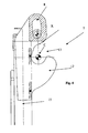
- Fig. 1 shows the structure of the seat on which a platform is mounted;
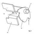
- Fig. 2 shows the structure of a platform;
- Fig. 3 shows the assembly of the seat structure of Fig. 1 and the platform structure;
- Fig. 4 is an enlarged view of a detail of the platform;
- Fig. 5 is an enlarged view of a detail ofthe system for securing the platform to the backrest;
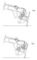
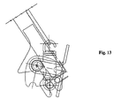
- Fig. 6 to Fig. 13 show a sequence of operations for mounting a platform to the backrest of a seat.
- Referring to the accompanying drawings, a vehicle seat is shown, which comprises a
seating surface 2, abackrest 3 and afolding platform 4 attached to the front part 5 ofthebackrest 3. - The
platform 4 is capable of pivoting (with an angle of at least 90°) between a first operating position, where it is received in a hollow 24 formed in the front part ofthebackrest 3, and a second operating position, where theplatform 4 projects out of the hollow 24 with a substantially and/or generally horizontal orientation. - This embodiment allows the platform to be used by the vehicle driver.
- In an alternative, not shown embodiment, which is designed to be used by a passenger seated in the rear row, the hollow 24 is formed in the rear part of the backrest.
- The
platform 4 is pivotally connected to thebackrest 3 by connection members - better described below - which allow particularly easy mounting of theplatform 4 to theseat backrest 3, without using any tool. - A pair of
brackets backrest 3, in symmetrical positions with respect to a longitudinal plane, and support aligned fixedpivot pins brackets - The
brackets fixed cams recesses 81, 82 formed thereon. - Preferably, the curved portions of each fixed
cams pivot pins recesses 81, 82 are in such relationship to form an angle of about 85° to 90° with respect to the fixedpivot pins - With reference to the fixed
pivot pins recesses - In the illustrated embodiment, the
brackets - The fixed
pivot pins - The
platform 4 comprises asupport structure 15, typically a U-shaped metal tube, as well as a pair of longitudinal rods and a transversely extending plate. - The U-shaped metal tube ends two plate-
like elements platform 4. - The plate-
like elements slots - In a possible embodiment, the axis X along which the two
slots platform 4. - The
slots - The
ends rod 9 have such a size as to fit in the recesses 81, 81; 82, 82 of the fixedcams - Bushes of antifriction material may also be mounted to the
ends transverse rod 9. - The
transverse rod 9 can slide along the direction of extension ofsuch slots - Since the
rod 9 is retained by thesprings slots - The plate-
like elements shaped portion curved end portion pivot pins - The
platform 4 is mounted to thebackrest 3 in the following manner. - By a translational motion (see Fig. 6 and Fig. 7), the plate-
like elements brackets - With an upwardly pivotal motion the contour of the
cams 18 is followed until theends transverse rod 9 engage the recess 81, 81 of thecams 18, 18 (Fig. 8). - In this condition, the generally hook-
shaped portions pivot pins - Here, the platform acts as a sort of first-class lever, whose fulcrum is the contact point of the contact surface between the hook-
shaped portion pivot pins springs rod 9 against thesupport structure 15 of theplatform 4. - When a downwardly driving force is applied to the
platform 4, thesprings hooks fixed pivot pins 17, 17 (see Fig. 11 and Fig. 12). - Now, the return force of the
springs platform 4 to translate and the fixedpivot pins recesses 13, 13 (Fig. 13). - Thus, the fixed
pivot pins hooks - Therefore the
platform 3 may be rotated between two positions, delimited by therecesses fixed cams - The user shall simply overcome the initial opposing force of the
springs ends transverse rod 9 engage the first or second recesses 81, 81; 82, 82. - The force opposed by the
springs 10, 10 - with theends transverse rod 9 being engaged - is an advantage because it reduces the risk of theplatform 4 to be accidentally deployed or folded, particularly in case of impacts or collisions.
Claims (13)
- A vehicle seat, comprising a seating surface (2) and a backrest (3), as well as a folding platform (4) attached to the front or rear part (5) of said backrest (3), said platform (4) being movable between a first position, where said platform (4) is received in a hollow (24) formed in said backrest (3), and a second position, where said platform (4) projects out of said hollow (24), said platform (4) comprising a support structure (15) and a pair of members (6, 6) for connecting said support structure (15) to the hollow of said backrest (3), said connecting members (6, 6) being arranged symmetrically with respect to the longitudinal plane of symmetry of the platform (4),
characterized in that said pair of connecting members (6, 6) comprises- two plate-like elements (7, 7) integral with said support structure (15), having a slot (8, 8), with an extension axis (X) and a generally hook-shaped portion (12, 12) which defines a hollow (13, 13);- a transverse rod (9), which fits in said slots (8, 8) and has ends (19, 19) projecting out of said slots (8, 8), said transverse rod (9) being able to slide along the direction of extension of said slots (8, 8) against the action of elastic return means (10, 10);- a pair of brackets (16, 16), integral with said backrest (3), which support pivot pins (17, 17) fitting in said hollows (13, 13) and cams (18, 18) which interfere with said ends (19, 19) of said transverse rod (9), said cams having two recesses (81, 82), corresponding to said first and second positions of said platform (4), and adapted to receive said ends (19, 19) of said transverse rod (9). - A seat as claimed in claim 1, modified in that said slots (7, 7) are replaced by forks (11, 11).
- A seat as claimed in claim 1 or 2, wherein a pair of antifriction bushes are mounted to said ends (19, 19) of said transverse rod (9).
- A seat as claimed in claim 1 or 2 or 3, wherein a pair of antifriction bushes are mounted to said pivot pins (17, 17).
- A seat as claimed in any preceding claim, wherein said brackets (16, 16) are generally and/or substantially Ω-shaped.
- A seat as claimed in any preceding claim, wherein said extension axis (X) of said slot or said fork is substantially parallel to said platform (4).
- A backrest (3) for a vehicle seat, having a hollow (24) in the part designed to act as a support surface for the back of a user, or in the part opposite the one designed to act as a support surface for the back of a user, characterized in that a pair of brackets (16, 16) are housed in said hollow (24), in symmetrical arrangement with respect to a longitudinal plane and integral with said backrest (3), and support aligned fixed pivot pins (17, 17) and parallel fixed cams (18, 18), which have a curved portion with two recesses (81, 82) formed thereon.
- A backrest as claimed in claim 8, wherein said curved portion of said fixed cams (18, 18) forms an angle of at least 100° with respect to the axis of said pivot pins (17, 17) and wherein said two recesses (81, 82) are in such relationship as to form an angle of about 85° to 90° with respect to said pivot pins (17, 17).
- A backrest as claimed in claim 7 or 8, wherein said brackets (16, 16) are generally and/or substantially Ω-shaped.
- A backrest as claimed in claim 7 or 8 or 9, wherein antifriction bushes are mounted to said pivot pins (17, 17).
- A platform (4) for a vehicle seat, comprising a support structure (15), characterized in that it comprises:- two plate-like elements (7, 7) which are arranged symmetrically with respect to the longitudinal plane of symmetry of the platform (4) and are integral with said support structure (15), said plate-like elements (7, 7) having a slot (8, 8) and a generally hook-shaped portion (12, 12) which defines a recess (13, 13);- a transverse rod (9), which fits in said slots (8, 8) and has ends (19, 19) projecting out of said slots (8, 8), said transverse rod (9) being able to slide along the direction of extension of said slots (8, 8) against the action of elastic return means (10, 10).
- A platform as claimed in claim 13, wherein said ends (19, 19) of said transverse rod (9) are fitted with antifriction bushes.
- A platform as claimed in claim 12 or 13, modified in that said slots (7, 7) are replaced by forks (11, 11).
Applications Claiming Priority (1)
| Application Number | Priority Date | Filing Date | Title |
|---|---|---|---|
| ITMI20060175 ITMI20060175A1 (en) | 2006-02-02 | 2006-02-02 | VEHICLE SEAT WITH CONCEALED SHELF |
Publications (2)
| Publication Number | Publication Date |
|---|---|
| EP1816028A2 true EP1816028A2 (en) | 2007-08-08 |
| EP1816028A3 EP1816028A3 (en) | 2012-07-18 |
Family
ID=38069344
Family Applications (1)
| Application Number | Title | Priority Date | Filing Date |
|---|---|---|---|
| EP07001825A Withdrawn EP1816028A3 (en) | 2006-02-02 | 2007-01-29 | Vehicle seat having a folding shelf |
Country Status (2)
| Country | Link |
|---|---|
| EP (1) | EP1816028A3 (en) |
| IT (1) | ITMI20060175A1 (en) |
Cited By (1)
| Publication number | Priority date | Publication date | Assignee | Title |
|---|---|---|---|---|
| JP2023067035A (en) * | 2021-10-29 | 2023-05-16 | 株式会社プラッツ | bed board |
Citations (1)
| Publication number | Priority date | Publication date | Assignee | Title |
|---|---|---|---|---|
| ITMI20010574A1 (en) | 2001-03-19 | 2002-09-19 | Isringhausen S P A | VEHICLE SEAT |
Family Cites Families (5)
| Publication number | Priority date | Publication date | Assignee | Title |
|---|---|---|---|---|
| US2481943A (en) * | 1944-09-28 | 1949-09-13 | Pullman Standard Car Mfg Co | Seat and leg rest arrangement |
| US2653036A (en) * | 1951-08-01 | 1953-09-22 | James E Creel | Swingable vehicle step |
| DE3122299A1 (en) * | 1981-06-04 | 1983-01-05 | Keiper Recaro GmbH & Co, 7312 Kirchheim | VEHICLE SEAT, ESPECIALLY FOR AIRCRAFT AND OMNIBUSES |
| US5876092A (en) * | 1997-12-05 | 1999-03-02 | Industrial Technology Research Institute | Foldaway table behind the backrest of a seat |
| DE102004024559B4 (en) * | 2004-05-18 | 2007-09-06 | Recaro Aircraft Seating Gmbh & Co. Kg | Table unit for a passenger seat |
-
2006
- 2006-02-02 IT ITMI20060175 patent/ITMI20060175A1/en unknown
-
2007
- 2007-01-29 EP EP07001825A patent/EP1816028A3/en not_active Withdrawn
Patent Citations (1)
| Publication number | Priority date | Publication date | Assignee | Title |
|---|---|---|---|---|
| ITMI20010574A1 (en) | 2001-03-19 | 2002-09-19 | Isringhausen S P A | VEHICLE SEAT |
Cited By (1)
| Publication number | Priority date | Publication date | Assignee | Title |
|---|---|---|---|---|
| JP2023067035A (en) * | 2021-10-29 | 2023-05-16 | 株式会社プラッツ | bed board |
Also Published As
| Publication number | Publication date |
|---|---|
| ITMI20060175A1 (en) | 2007-08-03 |
| EP1816028A3 (en) | 2012-07-18 |
Similar Documents
| Publication | Publication Date | Title |
|---|---|---|
| US7828358B2 (en) | Storable seat for vehicle | |
| US6866339B2 (en) | Head rest apparatus | |
| US20070194613A1 (en) | Vehicle seat apparatus | |
| US8616653B2 (en) | Frame structure of seat cushion for vehicle seat | |
| WO2012138472A2 (en) | Seat assembly having a front cushion module | |
| CN109476242B (en) | Longitudinal adjusters and vehicle seats | |
| CN103770673A (en) | Vehicle seat | |
| CN101376348A (en) | Vehicle seats | |
| CN108602454A (en) | car seat | |
| EP1945478B1 (en) | Front row seat assembly having fold flat mechanism with forward cushion movement | |
| CN103057442A (en) | Longitudinal-direction-changeable movable foldable seat | |
| CN101087705B (en) | Automobile seat | |
| JP5483557B2 (en) | Vehicle seat | |
| US8960691B2 (en) | Apparatus and method for damper adjustments for a horizontal suspension | |
| EP2046600B1 (en) | Seat assembly provided with an articulated-quadrilateral supporting device for a motor vehicle | |
| US8434820B2 (en) | Vehicle seat with securing device for a support element | |
| EP1816028A2 (en) | Vehicle seat having a folding shelf | |
| US7766430B2 (en) | Second row seat assembly having fold flat mechanism with forward cushion movement | |
| CN113335157A (en) | Vehicle seat | |
| CN101746334B (en) | Clutch mechanism for vehicle seat | |
| JP6234949B2 (en) | Vehicle seat table equipment | |
| KR20050100899A (en) | Device for reclining rear seatback of vehicle | |
| EP2106963A1 (en) | Headrest for motor vehicle seats | |
| JP4076423B2 (en) | A mechanism that allows the seat to move back and forth | |
| WO2010001253A1 (en) | Seat structure - cushion pan with a flexible hinge paddle |
Legal Events
| Date | Code | Title | Description |
|---|---|---|---|
| PUAI | Public reference made under article 153(3) epc to a published international application that has entered the european phase |
Free format text: ORIGINAL CODE: 0009012 |
|
| AK | Designated contracting states |
Kind code of ref document: A2 Designated state(s): AT BE BG CH CY CZ DE DK EE ES FI FR GB GR HU IE IS IT LI LT LU LV MC NL PL PT RO SE SI SK TR |
|
| AX | Request for extension of the european patent |
Extension state: AL BA HR MK YU |
|
| PUAL | Search report despatched |
Free format text: ORIGINAL CODE: 0009013 |
|
| AK | Designated contracting states |
Kind code of ref document: A3 Designated state(s): AT BE BG CH CY CZ DE DK EE ES FI FR GB GR HU IE IS IT LI LT LU LV MC NL PL PT RO SE SI SK TR |
|
| AX | Request for extension of the european patent |
Extension state: AL BA HR MK RS |
|
| RIC1 | Information provided on ipc code assigned before grant |
Ipc: B60R 7/04 20060101ALI20120608BHEP Ipc: B60N 3/00 20060101AFI20120608BHEP |
|
| AKY | No designation fees paid | ||
| REG | Reference to a national code |
Ref country code: DE Ref legal event code: R108 |
|
| REG | Reference to a national code |
Ref country code: DE Ref legal event code: R108 Effective date: 20130327 |
|
| STAA | Information on the status of an ep patent application or granted ep patent |
Free format text: STATUS: THE APPLICATION IS DEEMED TO BE WITHDRAWN |
|
| 18D | Application deemed to be withdrawn |
Effective date: 20130119 |