EP1813819B1 - Centrifugal Pump - Google Patents
Centrifugal Pump Download PDFInfo
- Publication number
- EP1813819B1 EP1813819B1 EP07000756A EP07000756A EP1813819B1 EP 1813819 B1 EP1813819 B1 EP 1813819B1 EP 07000756 A EP07000756 A EP 07000756A EP 07000756 A EP07000756 A EP 07000756A EP 1813819 B1 EP1813819 B1 EP 1813819B1
- Authority
- EP
- European Patent Office
- Prior art keywords
- impeller
- centrifugal pump
- shaft
- sealing disc
- sealing
- Prior art date
- Legal status (The legal status is an assumption and is not a legal conclusion. Google has not performed a legal analysis and makes no representation as to the accuracy of the status listed.)
- Active
Links
- 238000007789 sealing Methods 0.000 claims description 40
- 239000007788 liquid Substances 0.000 claims description 11
- 238000005192 partition Methods 0.000 claims description 2
- 239000012530 fluid Substances 0.000 abstract 2
- 238000001816 cooling Methods 0.000 description 3
- 238000005461 lubrication Methods 0.000 description 3
- 239000007787 solid Substances 0.000 description 3
- 241001295925 Gegenes Species 0.000 description 1
- 238000004140 cleaning Methods 0.000 description 1
- 238000010276 construction Methods 0.000 description 1
- 239000002655 kraft paper Substances 0.000 description 1
- 239000002245 particle Substances 0.000 description 1
- 230000002093 peripheral effect Effects 0.000 description 1
Images


Classifications
-
- F—MECHANICAL ENGINEERING; LIGHTING; HEATING; WEAPONS; BLASTING
- F04—POSITIVE - DISPLACEMENT MACHINES FOR LIQUIDS; PUMPS FOR LIQUIDS OR ELASTIC FLUIDS
- F04D—NON-POSITIVE-DISPLACEMENT PUMPS
- F04D29/00—Details, component parts, or accessories
- F04D29/08—Sealings
- F04D29/10—Shaft sealings
- F04D29/12—Shaft sealings using sealing-rings
- F04D29/126—Shaft sealings using sealing-rings especially adapted for liquid pumps
- F04D29/128—Shaft sealings using sealing-rings especially adapted for liquid pumps with special means for adducting cooling or sealing fluid
-
- F—MECHANICAL ENGINEERING; LIGHTING; HEATING; WEAPONS; BLASTING
- F04—POSITIVE - DISPLACEMENT MACHINES FOR LIQUIDS; PUMPS FOR LIQUIDS OR ELASTIC FLUIDS
- F04D—NON-POSITIVE-DISPLACEMENT PUMPS
- F04D29/00—Details, component parts, or accessories
- F04D29/08—Sealings
- F04D29/10—Shaft sealings
- F04D29/106—Shaft sealings especially adapted for liquid pumps
Definitions
- the invention relates to a centrifugal pump with an impeller, which sits on one end of a motor-driven shaft, wherein a mechanical seal on the side facing away from the impeller inlet side of the impeller surrounds the shaft.
- the object of the invention is to improve a centrifugal pump of the type mentioned so that optimal cooling and lubrication is ensured and in this case the solids, in particular suspended parts are safely dissipated.
- the partial flow through the seal chamber dissipates heat and solids, or suspended particles from the seal chamber, and also ensures optimum lubrication of the mechanical seal. It is created with regard to cooling, rinsing and cleaning an optimal environment for the mechanical seal.
- the passage channel is formed by at least one longitudinal recess, in particular a longitudinal groove, in the outer jacket of the shaft. It is also advantageous if the passage between the shaft and the central opening of the sealing disc is arranged.
- the pressure side of the pump can in particular be sealed to the sealing space through the sealing disk, wherein the partition between the pressure side, in particular the pressure chamber and the seal chamber has a particular annular opening which is closed in particular closed by a region of the sealing disc.
- the pressure of the pump pressure chamber bears against the sealing disk, on the side facing the impeller, so that the sealing disk presses the impeller in a direction over the shaft, which counteracts the pull of the impeller caused by the suction of the liquid into the impeller he follows.
- the sealing disk on the side facing away from the impeller has at least one groove which leads from the outer edge of the disk to the passage of the sealing disk. It is preferably proposed that the sealing disc has a particular annular contact surface for the mechanical seal.
- the housing 1 of a centrifugal pump 2 forms a pump chamber 3, in which an impeller 4 is mounted, which is fixed to one end of a shaft 5, which is driven by an electric motor, not shown.
- the impeller 4 has a coaxial inlet 6, with which the impeller from an inlet channel 7 sucks the liquid, which is connected to a suction nozzle 8.
- the sucked from the inlet 6 liquid is pushed out through impeller blade 9 from the impeller circumference, in a pressure chamber 10 and from there via a pressure channel to a discharge nozzle 11.
- a mechanical seal 12 On the side facing away from the inlet 6 of the impeller 4 sits on the shaft 5, a mechanical seal 12, the surrounded by a mechanical seal space 13 annular.
- the mechanical seal chamber 13 is connected to the pressure chamber 10 via a channel 22, which starts from the pressure chamber 10 and opens into the space 13.
- a circular sealing disc 14 coaxially mounted on the shaft 5 rotatably, so that it rotates with the shaft 5.
- the sealing disc 14 is located on one side on the back of the impeller, or on a coaxially projecting sleeve-shaped nozzle 15 of the impeller 4, and with its other side to a coaxial annular shoulder of the shaft 5, so that it is axially immovable against the shaft 5 is stuck on this.
- the sealing disc 14 has a central opening 16, with which it sits positively on the shaft 5.
- this opening 16 has at least one passage opening which allows the liquid to pass from the mechanical seal chamber 13 via a longitudinal channel 17, in particular a longitudinal groove, to the inlet 6 or the inlet opening of the rotor 4.
- This flow leading from the mechanical seal chamber 13 to the inlet 6 is further improved by the fact that the sealing disk has at least one groove 18 on the side facing away from the rotor, which groove leads from the outer edge of the sealing disk 14 to the passage of the sealing disk.
- two semicircular grooves 18 are arranged near the edge of the disk, with their end in each case merging in a radial region which leads to the passage 19.
- the sealing disc 14 has an inner annular abutment surface 20 in which the mechanical seal 12 abuts and which is interrupted only by the one or more end portions 18a of the grooves 18 of the sealing washer 14, these Nutenend Schemee 18a are arranged approximately radially to the outer ring or partially annular groove area to connect with the opening 16 and the longitudinal channel 17.
- the sliding ring sealing space 13 is connected to the pressure chamber 10 via an annular coaxial opening 19 when the sealing disc 14 is missing.
- the sealing disc 14 closes this opening 19, so that the pressure in the pressure chamber 10 rests against the impeller 4 facing side of the sealing disc 14.
- the sealing disk 14 is pressed by the pressure in the pressure chamber 10 in the direction of the electric motor and thus exerted a pressure on the impeller 4 via the shaft 5 in the same direction. This pressure is opposite to the force that generates the impeller 4 during the suction of the liquid.
Abstract
Description
Die Erfindung betrifft eine Kreiselpumpe mit einem Laufrad, das auf einem Ende einer motorisch angetriebenen Welle sitzt, wobei eine Gleitringdichtung auf der dem Laufradeinlass abgewandten Seite des Laufrades die Welle umgibt.The invention relates to a centrifugal pump with an impeller, which sits on one end of a motor-driven shaft, wherein a mechanical seal on the side facing away from the impeller inlet side of the impeller surrounds the shaft.
Es ist bekannt, das Laufrad einer Kreiselpumpe über eine Welle von einem Elektromotor anzutreiben. Das Laufrad saugt über einen koaxialen mittigen Einlass die Flüssigkeit an und die Flügel des Laufrades drücken die Flüssigkeit über den äußeren Rand des Laufrades in eine Druckkammer, von der der Druckkanal, bzw. der Druckstutzen abgeht. Die Pumpenwelle ist hierbei auf der dem Laufrad abgewandten Seite mittels einer Gleitringdichtung zur Atmosphärenseite abgedichtet. Bei dieser Konstruktion hat es sich gezeigt, dass Kühlung, Feststoffabfuhr und Schmierung ungenügend sind.It is known to drive the impeller of a centrifugal pump via a shaft of an electric motor. The impeller sucks the liquid via a coaxial central inlet and the impeller blades push the liquid over the outer edge of the impeller into a pressure chamber from which the pressure channel or the discharge nozzle is discharged. The pump shaft is in this case sealed on the side facing away from the impeller by means of a mechanical seal to the atmosphere side. In this construction, it has been found that cooling, solids removal and lubrication are insufficient.
Aus der
Aufgabe der Erfindung ist es, eine Kreiselpumpe der Eingangs genannten Art so zu verbessern, dass eine optimale Kühlung und Schmierung gewährleistet ist und hierbei die Feststoffe, insbesondere Schwebeteile sicher abgeführt werden.The object of the invention is to improve a centrifugal pump of the type mentioned so that optimal cooling and lubrication is ensured and in this case the solids, in particular suspended parts are safely dissipated.
Diese Aufgabe wird erfindungsgemäß dadurch gelöst,
- dass die Gleitringdichtung von einem Dichtungsraum umgeben ist, der von einem Teilstrom der geförderten Flüssigkeit durchströmt ist,
- dass zwischen dem Laufrad und der Gleitringdichtung eine umlaufende Dichtscheibe auf der Welle in axialer Richtung fest ist,
- dass die Dichtscheibe (14) eine axiale Kraft gegen die axiale Zugkraft des Laufrades (4) bewirkt, und
- dass die Dichtscheibe für den Flüssigkeitsteilstrom mindestens einen Durchlass aufweist, der mit mindestens einem Durchlasskanal verbunden ist, der zum Laufradeinlass führt.
- the mechanical seal is surrounded by a sealing space through which flows a partial flow of the conveyed liquid,
- in that between the impeller and the mechanical seal a peripheral sealing disc is fixed on the shaft in the axial direction,
- that the sealing disc (14) causes an axial force against the axial tensile force of the impeller (4), and
- in that the liquid partial flow sealing disk has at least one passage which is connected to at least one passage channel leading to the impeller inlet.
Der den Dichtungsraum durchströmende Teilstrom führt Wärme und Feststoffe, bzw. Schwebeteile aus dem Dichtungsraum heraus und sorgt darüber hinaus für eine optimale Schmierung der Gleitringdichtung. Es wird bezüglich Kühlung, Umspülung und Reinigung eine optimale Umgebung für die Gleitringdichtung geschaffen.The partial flow through the seal chamber dissipates heat and solids, or suspended particles from the seal chamber, and also ensures optimum lubrication of the mechanical seal. It is created with regard to cooling, rinsing and cleaning an optimal environment for the mechanical seal.
Vorzugsweise wird vorgeschlagen, dass der Durchlasskanal von mindestens einer Längsausnehmung insbesondere einer Längsnut in dem Außenmantel der Welle gebildet ist. Auch ist es von Vorteil, wenn der Durchlass zwischen der Welle und der mittigen Öffnung der Dichtscheibe angeordnet ist.It is preferably proposed that the passage channel is formed by at least one longitudinal recess, in particular a longitudinal groove, in the outer jacket of the shaft. It is also advantageous if the passage between the shaft and the central opening of the sealing disc is arranged.
Besonders vorteilhaft ist es, wenn der den Dichtungsraum durchfließende Teilstrom von der Druckseite der Pumpe abgezweigt ist.It is particularly advantageous if the partial flow flowing through the sealing space is branched off from the pressure side of the pump.
Hierbei kann die Druckseite der Pumpe insbesondere eine Druckkammer zum Dichtungsraum hin durch die Dichtscheibe abgedichtet sein, wobei die Trennwand zwischen der Druckseite insbesondere der Druckkammer und dem Dichtungsraum eine insbesondere ringförmige Öffnung aufweist, die von einem Bereich der Dichtscheibe geschlossen insbesondere ausgefüllt ist. Hierdurch liegt an der Dichtscheibe, an der dem Laufrad zugewandten Seite, der Druck der Pumpendruckkammer an, so dass die Dichtscheibe über die Welle das Laufrad in eine Richtung drückt, die dem Zug des Laufrades entgegenwirkt, der durch das Ansaugen der Flüssigkeit in das Laufrad hinein erfolgt.In this case, the pressure side of the pump can in particular be sealed to the sealing space through the sealing disk, wherein the partition between the pressure side, in particular the pressure chamber and the seal chamber has a particular annular opening which is closed in particular closed by a region of the sealing disc. As a result, the pressure of the pump pressure chamber bears against the sealing disk, on the side facing the impeller, so that the sealing disk presses the impeller in a direction over the shaft, which counteracts the pull of the impeller caused by the suction of the liquid into the impeller he follows.
Um die Zirkulation der Strömung zu verbessern wird vorgeschlagen, dass die Dichtscheibe auf der dem Laufrad abgewandten Seite mindestens eine Nut aufweist, die vom Scheibenaußenrand zum Durchlass der Dichtscheibe führt. Vorzugsweise wird vorgeschlagen, dass die Dichtscheibe eine insbesondere ringförmige Anlagefläche für die Gleitringdichtung aufweist.In order to improve the circulation of the flow, it is proposed that the sealing disk on the side facing away from the impeller has at least one groove which leads from the outer edge of the disk to the passage of the sealing disk. It is preferably proposed that the sealing disc has a particular annular contact surface for the mechanical seal.
Ein Ausführungsbeispiel der Erfindung ist in den Zeichnungen dargestellt und wird im Folgenden näher beschrieben. Es zeigen:
- Figur 1
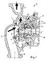
- einen axialen Schnitt durch die Kreiselpumpe,
Figur 2- eine perspektivische Ansicht der Dichtscheibe und
Figur 3- eine perspektivische Ansicht der Welle.
- FIG. 1
- an axial section through the centrifugal pump,
- FIG. 2
- a perspective view of the sealing disc and
- FIG. 3
- a perspective view of the shaft.
Das Gehäuse 1 einer Kreiselpumpe 2 bildet eine Pumpenkammer 3, in der ein Laufrad 4 gelagert ist, das auf einem Ende einer Welle 5 fest ist, die von einem nicht dargestellten Elektromotor antreibbar ist. Das Laufrad 4 besitzt einen koaxialen Einlass 6, mit dem das Laufrad aus einem Einlasskanal 7 die Flüssigkeit ansaugt, der mit einem Saugstutzen 8 verbunden ist.The housing 1 of a
Die vom Einlass 6 angesaugte Flüssigkeit wird über Laufradschaufel 9 aus dem Laufradumfang herausgedrückt, in eine Druckkammer 10 und von dort über einen Druckkanal zu einem Druckstutzen 11. Auf der dem Einlass 6 abgewandten Seite des Laufrades 4 sitzt auf der Welle 5 eine Gleitringdichtung 12, die von einem Gleitringdichtungsraum 13 ringförmig umgeben ist. Hierbei ist der Gleitringdichtungsraum 13 mit der Druckkammer 10 über einen Kanal 22 verbunden, der von der Druckkammer 10 ausgeht und im Raum 13 mündet.The sucked from the
Auf der Rückseite des Laufrades 4 und damit auf der dem Einlass 6 abgewandten Seite des Laufrades 4 ist eine kreisförmige Dichtscheibe 14 koaxial auf der Welle 5 drehfest befestigt, so dass sie mit der Welle 5 umläuft. Hierbei liegt die Dichtscheibe 14 auf ihrer einen Seite an der Rückseite des Laufrades, bzw. an einem koaxial vorstehenden buchsenförmigen Stutzen 15 des Laufrades 4 an, und mit ihrer anderen Seite an einer koaxialen Ringschulter der Welle 5, so dass sie axial unverschieblich gegenüber der Welle 5 auf dieser festsitzt.On the back of the
Die Dichtscheibe 14 besitzt eine mittige Öffnung 16, mit der sie formschlüssig auf der Welle 5 sitzt. Diese Öffnung 16 besitzt aber mindestens eine Durchlassöffnung, die die Flüssigkeit aus dem Gleitringdichtungsraum 13 über einen Längskanal 17, insbesondere eine Längsnut zum Einlass 6 bzw. der Einlassöffnung des Laufrades 4 hindurchlässt. Diese von dem Gleitringdichtungsraum 13 zum Einlass 6 führende Strömung wird noch dadurch verbessert, dass die Dichtscheibe auf der dem Laufrad abgewandten Seite mindestens eine Nut 18 aufweist, die vom Außenrand der Dichtscheibe 14 zum Durchlass der Dichtscheibe führt. Im Ausführungsbeispiel sind zwei halbkreisförmige Nuten 18 nahe dem Scheibenrand angeordnet, wobei ihr Ende jeweils in einem radialen Bereich übergeht, der zum Durchlass 19 führt. Die Dichtscheibe 14 weist eine innere ringförmige Anlagefläche 20 auf, in der die Gleitringdichtung 12 anliegt und die nur von der oder den Endbereichen 18a der Nuten 18 der Dichtscheibe 14 unterbrochen wird, wobei diese Nutenendbereiche 18a etwa radial angeordnet sind um den äußeren Ring oder teilringförmigen Nutenbereich mit der Öffnung 16 und dem Längskanal 17 zu verbinden.The sealing
Der Gleitringdichtungsraum 13 ist über eine ringförmige koaxiale Öffnung 19 mit der Druckkammer 10 verbunden, wenn die Dichtscheibe 14 fehlt. Die Dichtscheibe 14 schließt aber diese Öffnung 19, so dass der Druck in der Druckkammer 10 an der dem Laufrad 4 zugewandten Seite der Dichtscheibe 14 anliegt. Hierdurch wird durch den Druck in der Druckkammer 10 die Dichtscheibe 14 in Richtung des Elektromotors gedrückt und damit in gleicher Richtung ein Druck auf das Laufrad 4 über die Welle 5 ausgeübt. Dieser Druck ist entgegengesetzt der Kraft, die das Laufrad 4 beim Ansaugen der Flüssigkeit erzeugt.The sliding
Claims (8)
- Centrifugal pump (2) with an impeller (4), which sits on one end of a motor driven shaft (5), in which a slide ring seal (12) surrounds the shaft on the side of the impeller turned away from the impeller inlet (6), and the slide ring seal (12) is surrounded by a sealing area (13), through which part of the flow of liquid conveyed flows, characterised in that- a rotating sealing disc (14) is fixed to the shaft (5) in the axial direction between the impeller (4) and the slide ring seal (12),- the sealing disc (14) produces an axial force against the axial traction of the impeller (4), and- the sealing disc (14) has at least one admission (19) for the part of the flow of liquid, which is connected to at least one admission channel (17), which leads to the impeller inlet (6).
- Centrifugal pump (2) according to claim 1, characterised in that the admission channel (17) is formed by at least one longitudinal recess, particularly a longitudinal groove, in the outer casing of the shaft (5).
- Centrifugal pump (2) according to claim 1 or 2, characterised in that the admission (19) is arranged between the shaft (5) and the middle opening (16) of the sealing disc (14).
- Centrifugal pump (2) according to one of the previous claims, characterised in that the part of the flow passing through the sealing area (13) is branched off from the pressure side of the pump.
- Centrifugal pump (2) according to one of the previous claims, characterised in that the pressure side of the pump, particularly a pressure chamber (10), is sealed through the sealing disc (14) with reference to the pressure area.
- Centrifugal pump (2) according to claim 5, characterised in that the partition wall (21) between the pressure side, particularly the pressure chamber (10), and the sealing area (13) has a particularly ring shaped opening (19), which is closed, particularly filled up, by an area of the sealing disc (14).
- Centrifugal pump according to one of the previous claims, characterised in that the sealing disc (14) has at least one groove (18) on the side turned away from the impeller (4), which leads from the outer edge of the disc to the admission (19) of the sealing disc (14).
- Centrifugal pump according to one of the previous claims, characterised in that the sealing disc (14) has a particularly ring shaped bearing surface (20) for the slide ring seal (12).
Applications Claiming Priority (1)
| Application Number | Priority Date | Filing Date | Title |
|---|---|---|---|
| DE102006004266A DE102006004266A1 (en) | 2006-01-31 | 2006-01-31 | rotary pump |
Publications (3)
| Publication Number | Publication Date |
|---|---|
| EP1813819A2 EP1813819A2 (en) | 2007-08-01 |
| EP1813819A3 EP1813819A3 (en) | 2008-02-27 |
| EP1813819B1 true EP1813819B1 (en) | 2011-04-27 |
Family
ID=38024250
Family Applications (1)
| Application Number | Title | Priority Date | Filing Date |
|---|---|---|---|
| EP07000756A Active EP1813819B1 (en) | 2006-01-31 | 2007-01-16 | Centrifugal Pump |
Country Status (3)
| Country | Link |
|---|---|
| EP (1) | EP1813819B1 (en) |
| AT (1) | ATE507395T1 (en) |
| DE (2) | DE102006004266A1 (en) |
Families Citing this family (3)
| Publication number | Priority date | Publication date | Assignee | Title |
|---|---|---|---|---|
| CN113202809A (en) * | 2021-05-22 | 2021-08-03 | 中国计量大学 | Structure of totally-enclosed water pump capable of preventing liquid molecules from leaking out of pump |
| CN113357186A (en) * | 2021-05-22 | 2021-09-07 | 中国计量大学 | Structure of totally enclosed type water pump |
| CN113236599A (en) * | 2021-05-22 | 2021-08-10 | 中国计量大学 | Chemical pump structure capable of preventing liquid molecules conveyed in pump from leaking and with lift determined by motor |
Family Cites Families (10)
| Publication number | Priority date | Publication date | Assignee | Title |
|---|---|---|---|---|
| GB1120231A (en) * | 1964-07-08 | 1968-07-17 | Worthington Simpson | Rotary pumps |
| DE2914652A1 (en) * | 1979-04-11 | 1980-10-30 | Kloeckner Humboldt Deutz Ag | Compact hand-held microfiche reader - has two support plates hinged to grip microfiche with magnifying lens viewer |
| DE3432662C2 (en) * | 1984-09-05 | 1986-10-16 | Tanabe Machinery Co., Ltd., Tokio/Tokyo | Device for detecting a nominal size of a box blank for a box manufacturing machine |
| DE3438662C2 (en) * | 1984-10-22 | 1997-01-30 | Sihi Gmbh & Co Kg | Centrifugal pump for hot media |
| DE8601166U1 (en) * | 1986-01-18 | 1986-02-27 | Sihi Gmbh & Co Kg, 2210 Itzehoe | Pump for pumping hot water |
| DE8627766U1 (en) * | 1986-10-17 | 1988-02-11 | Sihi Gmbh & Co Kg | |
| DE3825799A1 (en) * | 1988-07-29 | 1990-02-01 | Messer Griesheim Gmbh | Centrifugal pump |
| DE3914652A1 (en) * | 1989-05-03 | 1990-11-08 | Sihi Gmbh & Co Kg | CENTRIFUGAL PUMP |
| CA2015777C (en) * | 1990-04-30 | 1993-10-12 | Lynn P. Tessier | Centrifugal pump |
| GB2290113B (en) * | 1994-05-31 | 1998-07-15 | Ingersoll Dresser Pump Co | Centrifugal pump |
-
2006
- 2006-01-31 DE DE102006004266A patent/DE102006004266A1/en not_active Withdrawn
-
2007
- 2007-01-16 DE DE502007007033T patent/DE502007007033D1/en active Active
- 2007-01-16 EP EP07000756A patent/EP1813819B1/en active Active
- 2007-01-16 AT AT07000756T patent/ATE507395T1/en active
Also Published As
| Publication number | Publication date |
|---|---|
| ATE507395T1 (en) | 2011-05-15 |
| DE502007007033D1 (en) | 2011-06-09 |
| EP1813819A3 (en) | 2008-02-27 |
| DE102006004266A1 (en) | 2007-08-02 |
| EP1813819A2 (en) | 2007-08-01 |
Similar Documents
| Publication | Publication Date | Title |
|---|---|---|
| DE3014425C2 (en) | Side channel pump | |
| EP1811184B1 (en) | Impeller of a pump unit and corresponding pump unit | |
| EP1828615B1 (en) | Arrangement of a shaft with a slip-ring seal mounted thereon | |
| EP3433496A1 (en) | Magnetic drive pump | |
| EP1813819B1 (en) | Centrifugal Pump | |
| DE102007032228A1 (en) | Self-priming pump aggregation | |
| EP2864640B1 (en) | Motorized centrifugal pump with a rotary seal | |
| EP2535589B1 (en) | Cutting assembly pump | |
| EP2348219B1 (en) | Coolant pump system | |
| EP2322803B1 (en) | Pump with a magnetic coupling | |
| DE102007020218A1 (en) | feed pump | |
| DE4415566C2 (en) | Side channel pump | |
| DE102015212653B4 (en) | HOUSEHOLD APPLIANCE | |
| DE10019819A1 (en) | Pump housing esp. for circulation pump for household machines consists of separate upper and lower sections with intermediate sealing ring loaded in radial direction | |
| EP1327781B1 (en) | Self-priming centrifugal pump | |
| DE102015212654B4 (en) | HOUSEHOLD APPLIANCE | |
| EP3090185B1 (en) | Centrifugal pump comprising a cutting device | |
| DE102010010593B4 (en) | rotary pump | |
| DE2125040B2 (en) | Centrifugal pump | |
| EP1457682B1 (en) | Centrifugal pump | |
| WO1999039105A1 (en) | Centrifugal pump impeller having a radial structure | |
| DE102011077545A1 (en) | Centrifugal pump with integrated cutting unit | |
| DE112005002258T5 (en) | Impeller with abradable tip | |
| EP2420677A1 (en) | Multi-layer circulation pump | |
| DE102018213016B4 (en) | pump assembly |
Legal Events
| Date | Code | Title | Description |
|---|---|---|---|
| PUAI | Public reference made under article 153(3) epc to a published international application that has entered the european phase |
Free format text: ORIGINAL CODE: 0009012 |
|
| AK | Designated contracting states |
Kind code of ref document: A2 Designated state(s): AT BE BG CH CY CZ DE DK EE ES FI FR GB GR HU IE IS IT LI LT LU LV MC NL PL PT RO SE SI SK TR |
|
| AX | Request for extension of the european patent |
Extension state: AL BA HR MK YU |
|
| PUAL | Search report despatched |
Free format text: ORIGINAL CODE: 0009013 |
|
| AK | Designated contracting states |
Kind code of ref document: A3 Designated state(s): AT BE BG CH CY CZ DE DK EE ES FI FR GB GR HU IE IS IT LI LT LU LV MC NL PL PT RO SE SI SK TR |
|
| AX | Request for extension of the european patent |
Extension state: AL BA HR MK YU |
|
| 17P | Request for examination filed |
Effective date: 20080403 |
|
| 17Q | First examination report despatched |
Effective date: 20080609 |
|
| AKX | Designation fees paid |
Designated state(s): AT BE BG CH CY CZ DE DK EE ES FI FR GB GR HU IE IS IT LI LT LU LV MC NL PL PT RO SE SI SK TR |
|
| GRAP | Despatch of communication of intention to grant a patent |
Free format text: ORIGINAL CODE: EPIDOSNIGR1 |
|
| GRAS | Grant fee paid |
Free format text: ORIGINAL CODE: EPIDOSNIGR3 |
|
| GRAA | (expected) grant |
Free format text: ORIGINAL CODE: 0009210 |
|
| RAP1 | Party data changed (applicant data changed or rights of an application transferred) |
Owner name: WILO SE |
|
| AK | Designated contracting states |
Kind code of ref document: B1 Designated state(s): AT BE BG CH CY CZ DE DK EE ES FI FR GB GR HU IE IS IT LI LT LU LV MC NL PL PT RO SE SI SK TR |
|
| REG | Reference to a national code |
Ref country code: GB Ref legal event code: FG4D Free format text: NOT ENGLISH |
|
| REG | Reference to a national code |
Ref country code: CH Ref legal event code: EP |
|
| REG | Reference to a national code |
Ref country code: IE Ref legal event code: FG4D Free format text: LANGUAGE OF EP DOCUMENT: GERMAN |
|
| REF | Corresponds to: |
Ref document number: 502007007033 Country of ref document: DE Date of ref document: 20110609 Kind code of ref document: P |
|
| REG | Reference to a national code |
Ref country code: DE Ref legal event code: R096 Ref document number: 502007007033 Country of ref document: DE Effective date: 20110609 |
|
| REG | Reference to a national code |
Ref country code: NL Ref legal event code: VDEP Effective date: 20110427 |
|
| LTIE | Lt: invalidation of european patent or patent extension |
Effective date: 20110427 |
|
| PG25 | Lapsed in a contracting state [announced via postgrant information from national office to epo] |
Ref country code: SE Free format text: LAPSE BECAUSE OF FAILURE TO SUBMIT A TRANSLATION OF THE DESCRIPTION OR TO PAY THE FEE WITHIN THE PRESCRIBED TIME-LIMIT Effective date: 20110427 Ref country code: PT Free format text: LAPSE BECAUSE OF FAILURE TO SUBMIT A TRANSLATION OF THE DESCRIPTION OR TO PAY THE FEE WITHIN THE PRESCRIBED TIME-LIMIT Effective date: 20110829 Ref country code: LT Free format text: LAPSE BECAUSE OF FAILURE TO SUBMIT A TRANSLATION OF THE DESCRIPTION OR TO PAY THE FEE WITHIN THE PRESCRIBED TIME-LIMIT Effective date: 20110427 |
|
| REG | Reference to a national code |
Ref country code: IE Ref legal event code: FD4D |
|
| PG25 | Lapsed in a contracting state [announced via postgrant information from national office to epo] |
Ref country code: IS Free format text: LAPSE BECAUSE OF FAILURE TO SUBMIT A TRANSLATION OF THE DESCRIPTION OR TO PAY THE FEE WITHIN THE PRESCRIBED TIME-LIMIT Effective date: 20110827 Ref country code: ES Free format text: LAPSE BECAUSE OF FAILURE TO SUBMIT A TRANSLATION OF THE DESCRIPTION OR TO PAY THE FEE WITHIN THE PRESCRIBED TIME-LIMIT Effective date: 20110807 Ref country code: SI Free format text: LAPSE BECAUSE OF FAILURE TO SUBMIT A TRANSLATION OF THE DESCRIPTION OR TO PAY THE FEE WITHIN THE PRESCRIBED TIME-LIMIT Effective date: 20110427 Ref country code: LV Free format text: LAPSE BECAUSE OF FAILURE TO SUBMIT A TRANSLATION OF THE DESCRIPTION OR TO PAY THE FEE WITHIN THE PRESCRIBED TIME-LIMIT Effective date: 20110427 Ref country code: FI Free format text: LAPSE BECAUSE OF FAILURE TO SUBMIT A TRANSLATION OF THE DESCRIPTION OR TO PAY THE FEE WITHIN THE PRESCRIBED TIME-LIMIT Effective date: 20110427 Ref country code: CY Free format text: LAPSE BECAUSE OF FAILURE TO SUBMIT A TRANSLATION OF THE DESCRIPTION OR TO PAY THE FEE WITHIN THE PRESCRIBED TIME-LIMIT Effective date: 20110427 Ref country code: GR Free format text: LAPSE BECAUSE OF FAILURE TO SUBMIT A TRANSLATION OF THE DESCRIPTION OR TO PAY THE FEE WITHIN THE PRESCRIBED TIME-LIMIT Effective date: 20110728 |
|
| PG25 | Lapsed in a contracting state [announced via postgrant information from national office to epo] |
Ref country code: NL Free format text: LAPSE BECAUSE OF FAILURE TO SUBMIT A TRANSLATION OF THE DESCRIPTION OR TO PAY THE FEE WITHIN THE PRESCRIBED TIME-LIMIT Effective date: 20110427 |
|
| PG25 | Lapsed in a contracting state [announced via postgrant information from national office to epo] |
Ref country code: CZ Free format text: LAPSE BECAUSE OF FAILURE TO SUBMIT A TRANSLATION OF THE DESCRIPTION OR TO PAY THE FEE WITHIN THE PRESCRIBED TIME-LIMIT Effective date: 20110427 Ref country code: EE Free format text: LAPSE BECAUSE OF FAILURE TO SUBMIT A TRANSLATION OF THE DESCRIPTION OR TO PAY THE FEE WITHIN THE PRESCRIBED TIME-LIMIT Effective date: 20110427 Ref country code: IE Free format text: LAPSE BECAUSE OF FAILURE TO SUBMIT A TRANSLATION OF THE DESCRIPTION OR TO PAY THE FEE WITHIN THE PRESCRIBED TIME-LIMIT Effective date: 20110427 |
|
| PG25 | Lapsed in a contracting state [announced via postgrant information from national office to epo] |
Ref country code: PL Free format text: LAPSE BECAUSE OF FAILURE TO SUBMIT A TRANSLATION OF THE DESCRIPTION OR TO PAY THE FEE WITHIN THE PRESCRIBED TIME-LIMIT Effective date: 20110427 Ref country code: SK Free format text: LAPSE BECAUSE OF FAILURE TO SUBMIT A TRANSLATION OF THE DESCRIPTION OR TO PAY THE FEE WITHIN THE PRESCRIBED TIME-LIMIT Effective date: 20110427 Ref country code: RO Free format text: LAPSE BECAUSE OF FAILURE TO SUBMIT A TRANSLATION OF THE DESCRIPTION OR TO PAY THE FEE WITHIN THE PRESCRIBED TIME-LIMIT Effective date: 20110427 Ref country code: DK Free format text: LAPSE BECAUSE OF FAILURE TO SUBMIT A TRANSLATION OF THE DESCRIPTION OR TO PAY THE FEE WITHIN THE PRESCRIBED TIME-LIMIT Effective date: 20110427 |
|
| PLBE | No opposition filed within time limit |
Free format text: ORIGINAL CODE: 0009261 |
|
| STAA | Information on the status of an ep patent application or granted ep patent |
Free format text: STATUS: NO OPPOSITION FILED WITHIN TIME LIMIT |
|
| 26N | No opposition filed |
Effective date: 20120130 |
|
| REG | Reference to a national code |
Ref country code: DE Ref legal event code: R097 Ref document number: 502007007033 Country of ref document: DE Effective date: 20120130 |
|
| BERE | Be: lapsed |
Owner name: WILO SE Effective date: 20120131 |
|
| PG25 | Lapsed in a contracting state [announced via postgrant information from national office to epo] |
Ref country code: MC Free format text: LAPSE BECAUSE OF NON-PAYMENT OF DUE FEES Effective date: 20120131 |
|
| REG | Reference to a national code |
Ref country code: CH Ref legal event code: PL |
|
| PG25 | Lapsed in a contracting state [announced via postgrant information from national office to epo] |
Ref country code: CH Free format text: LAPSE BECAUSE OF NON-PAYMENT OF DUE FEES Effective date: 20120131 Ref country code: LI Free format text: LAPSE BECAUSE OF NON-PAYMENT OF DUE FEES Effective date: 20120131 |
|
| PG25 | Lapsed in a contracting state [announced via postgrant information from national office to epo] |
Ref country code: BE Free format text: LAPSE BECAUSE OF NON-PAYMENT OF DUE FEES Effective date: 20120131 |
|
| REG | Reference to a national code |
Ref country code: AT Ref legal event code: MM01 Ref document number: 507395 Country of ref document: AT Kind code of ref document: T Effective date: 20120116 |
|
| PG25 | Lapsed in a contracting state [announced via postgrant information from national office to epo] |
Ref country code: BG Free format text: LAPSE BECAUSE OF FAILURE TO SUBMIT A TRANSLATION OF THE DESCRIPTION OR TO PAY THE FEE WITHIN THE PRESCRIBED TIME-LIMIT Effective date: 20110727 Ref country code: AT Free format text: LAPSE BECAUSE OF NON-PAYMENT OF DUE FEES Effective date: 20120116 |
|
| PG25 | Lapsed in a contracting state [announced via postgrant information from national office to epo] |
Ref country code: TR Free format text: LAPSE BECAUSE OF FAILURE TO SUBMIT A TRANSLATION OF THE DESCRIPTION OR TO PAY THE FEE WITHIN THE PRESCRIBED TIME-LIMIT Effective date: 20110427 |
|
| PG25 | Lapsed in a contracting state [announced via postgrant information from national office to epo] |
Ref country code: LU Free format text: LAPSE BECAUSE OF NON-PAYMENT OF DUE FEES Effective date: 20120116 |
|
| PG25 | Lapsed in a contracting state [announced via postgrant information from national office to epo] |
Ref country code: HU Free format text: LAPSE BECAUSE OF FAILURE TO SUBMIT A TRANSLATION OF THE DESCRIPTION OR TO PAY THE FEE WITHIN THE PRESCRIBED TIME-LIMIT Effective date: 20070116 |
|
| PGFP | Annual fee paid to national office [announced via postgrant information from national office to epo] |
Ref country code: GB Payment date: 20150114 Year of fee payment: 9 |
|
| REG | Reference to a national code |
Ref country code: FR Ref legal event code: PLFP Year of fee payment: 10 |
|
| GBPC | Gb: european patent ceased through non-payment of renewal fee |
Effective date: 20160116 |
|
| PG25 | Lapsed in a contracting state [announced via postgrant information from national office to epo] |
Ref country code: GB Free format text: LAPSE BECAUSE OF NON-PAYMENT OF DUE FEES Effective date: 20160116 |
|
| REG | Reference to a national code |
Ref country code: FR Ref legal event code: PLFP Year of fee payment: 11 |
|
| REG | Reference to a national code |
Ref country code: FR Ref legal event code: PLFP Year of fee payment: 12 |
|
| PGFP | Annual fee paid to national office [announced via postgrant information from national office to epo] |
Ref country code: IT Payment date: 20230103 Year of fee payment: 17 Ref country code: DE Payment date: 20221220 Year of fee payment: 17 |
|
| P01 | Opt-out of the competence of the unified patent court (upc) registered |
Effective date: 20230615 |
|
| PGFP | Annual fee paid to national office [announced via postgrant information from national office to epo] |
Ref country code: FR Payment date: 20231219 Year of fee payment: 18 |