EP1813794A1 - Procede de commande d'un groupe motopropulseur de vehicule automobile - Google Patents
Procede de commande d'un groupe motopropulseur de vehicule automobile Download PDFInfo
- Publication number
- EP1813794A1 EP1813794A1 EP07300748A EP07300748A EP1813794A1 EP 1813794 A1 EP1813794 A1 EP 1813794A1 EP 07300748 A EP07300748 A EP 07300748A EP 07300748 A EP07300748 A EP 07300748A EP 1813794 A1 EP1813794 A1 EP 1813794A1
- Authority
- EP
- European Patent Office
- Prior art keywords
- motor
- torque
- engine
- primary shaft
- coupling member
- Prior art date
- Legal status (The legal status is an assumption and is not a legal conclusion. Google has not performed a legal analysis and makes no representation as to the accuracy of the status listed.)
- Withdrawn
Links
- 238000000034 method Methods 0.000 title claims abstract description 19
- 230000008878 coupling Effects 0.000 claims abstract description 21
- 238000010168 coupling process Methods 0.000 claims abstract description 21
- 238000005859 coupling reaction Methods 0.000 claims abstract description 21
- 238000004026 adhesive bonding Methods 0.000 claims description 13
- 238000002347 injection Methods 0.000 claims description 5
- 239000007924 injection Substances 0.000 claims description 5
- 230000007704 transition Effects 0.000 claims description 3
- 230000010355 oscillation Effects 0.000 description 10
- 230000005540 biological transmission Effects 0.000 description 5
- 239000000243 solution Substances 0.000 description 3
- 230000001419 dependent effect Effects 0.000 description 2
- 239000000446 fuel Substances 0.000 description 2
- 230000035484 reaction time Effects 0.000 description 2
- 238000013459 approach Methods 0.000 description 1
- 230000033228 biological regulation Effects 0.000 description 1
- 238000002485 combustion reaction Methods 0.000 description 1
- 230000007423 decrease Effects 0.000 description 1
- 230000001627 detrimental effect Effects 0.000 description 1
- 230000000694 effects Effects 0.000 description 1
- 238000004519 manufacturing process Methods 0.000 description 1
- 238000005259 measurement Methods 0.000 description 1
- 230000021715 photosynthesis, light harvesting Effects 0.000 description 1
- 239000000843 powder Substances 0.000 description 1
Images

Classifications
-
- B—PERFORMING OPERATIONS; TRANSPORTING
- B60—VEHICLES IN GENERAL
- B60W—CONJOINT CONTROL OF VEHICLE SUB-UNITS OF DIFFERENT TYPE OR DIFFERENT FUNCTION; CONTROL SYSTEMS SPECIALLY ADAPTED FOR HYBRID VEHICLES; ROAD VEHICLE DRIVE CONTROL SYSTEMS FOR PURPOSES NOT RELATED TO THE CONTROL OF A PARTICULAR SUB-UNIT
- B60W30/00—Purposes of road vehicle drive control systems not related to the control of a particular sub-unit, e.g. of systems using conjoint control of vehicle sub-units
- B60W30/18—Propelling the vehicle
- B60W30/20—Reducing vibrations in the driveline
-
- B—PERFORMING OPERATIONS; TRANSPORTING
- B60—VEHICLES IN GENERAL
- B60W—CONJOINT CONTROL OF VEHICLE SUB-UNITS OF DIFFERENT TYPE OR DIFFERENT FUNCTION; CONTROL SYSTEMS SPECIALLY ADAPTED FOR HYBRID VEHICLES; ROAD VEHICLE DRIVE CONTROL SYSTEMS FOR PURPOSES NOT RELATED TO THE CONTROL OF A PARTICULAR SUB-UNIT
- B60W10/00—Conjoint control of vehicle sub-units of different type or different function
- B60W10/02—Conjoint control of vehicle sub-units of different type or different function including control of driveline clutches
-
- B—PERFORMING OPERATIONS; TRANSPORTING
- B60—VEHICLES IN GENERAL
- B60W—CONJOINT CONTROL OF VEHICLE SUB-UNITS OF DIFFERENT TYPE OR DIFFERENT FUNCTION; CONTROL SYSTEMS SPECIALLY ADAPTED FOR HYBRID VEHICLES; ROAD VEHICLE DRIVE CONTROL SYSTEMS FOR PURPOSES NOT RELATED TO THE CONTROL OF A PARTICULAR SUB-UNIT
- B60W10/00—Conjoint control of vehicle sub-units of different type or different function
- B60W10/04—Conjoint control of vehicle sub-units of different type or different function including control of propulsion units
- B60W10/06—Conjoint control of vehicle sub-units of different type or different function including control of propulsion units including control of combustion engines
-
- F—MECHANICAL ENGINEERING; LIGHTING; HEATING; WEAPONS; BLASTING
- F02—COMBUSTION ENGINES; HOT-GAS OR COMBUSTION-PRODUCT ENGINE PLANTS
- F02D—CONTROLLING COMBUSTION ENGINES
- F02D41/00—Electrical control of supply of combustible mixture or its constituents
- F02D41/02—Circuit arrangements for generating control signals
- F02D41/021—Introducing corrections for particular conditions exterior to the engine
- F02D41/0215—Introducing corrections for particular conditions exterior to the engine in relation with elements of the transmission
- F02D41/023—Introducing corrections for particular conditions exterior to the engine in relation with elements of the transmission in relation with the gear ratio shifting
-
- F—MECHANICAL ENGINEERING; LIGHTING; HEATING; WEAPONS; BLASTING
- F02—COMBUSTION ENGINES; HOT-GAS OR COMBUSTION-PRODUCT ENGINE PLANTS
- F02D—CONTROLLING COMBUSTION ENGINES
- F02D41/00—Electrical control of supply of combustible mixture or its constituents
- F02D41/02—Circuit arrangements for generating control signals
- F02D41/04—Introducing corrections for particular operating conditions
- F02D41/10—Introducing corrections for particular operating conditions for acceleration
-
- F—MECHANICAL ENGINEERING; LIGHTING; HEATING; WEAPONS; BLASTING
- F02—COMBUSTION ENGINES; HOT-GAS OR COMBUSTION-PRODUCT ENGINE PLANTS
- F02D—CONTROLLING COMBUSTION ENGINES
- F02D41/00—Electrical control of supply of combustible mixture or its constituents
- F02D41/02—Circuit arrangements for generating control signals
- F02D41/14—Introducing closed-loop corrections
- F02D41/1497—With detection of the mechanical response of the engine
-
- F—MECHANICAL ENGINEERING; LIGHTING; HEATING; WEAPONS; BLASTING
- F16—ENGINEERING ELEMENTS AND UNITS; GENERAL MEASURES FOR PRODUCING AND MAINTAINING EFFECTIVE FUNCTIONING OF MACHINES OR INSTALLATIONS; THERMAL INSULATION IN GENERAL
- F16H—GEARING
- F16H63/00—Control outputs from the control unit to change-speed- or reversing-gearings for conveying rotary motion or to other devices than the final output mechanism
- F16H63/40—Control outputs from the control unit to change-speed- or reversing-gearings for conveying rotary motion or to other devices than the final output mechanism comprising signals other than signals for actuating the final output mechanisms
- F16H63/50—Signals to an engine or motor
- F16H63/502—Signals to an engine or motor for smoothing gear shifts
-
- B—PERFORMING OPERATIONS; TRANSPORTING
- B60—VEHICLES IN GENERAL
- B60W—CONJOINT CONTROL OF VEHICLE SUB-UNITS OF DIFFERENT TYPE OR DIFFERENT FUNCTION; CONTROL SYSTEMS SPECIALLY ADAPTED FOR HYBRID VEHICLES; ROAD VEHICLE DRIVE CONTROL SYSTEMS FOR PURPOSES NOT RELATED TO THE CONTROL OF A PARTICULAR SUB-UNIT
- B60W2710/00—Output or target parameters relating to a particular sub-units
- B60W2710/06—Combustion engines, Gas turbines
- B60W2710/0616—Position of fuel or air injector
-
- F—MECHANICAL ENGINEERING; LIGHTING; HEATING; WEAPONS; BLASTING
- F02—COMBUSTION ENGINES; HOT-GAS OR COMBUSTION-PRODUCT ENGINE PLANTS
- F02D—CONTROLLING COMBUSTION ENGINES
- F02D2250/00—Engine control related to specific problems or objectives
- F02D2250/18—Control of the engine output torque
-
- F—MECHANICAL ENGINEERING; LIGHTING; HEATING; WEAPONS; BLASTING
- F02—COMBUSTION ENGINES; HOT-GAS OR COMBUSTION-PRODUCT ENGINE PLANTS
- F02D—CONTROLLING COMBUSTION ENGINES
- F02D2250/00—Engine control related to specific problems or objectives
- F02D2250/18—Control of the engine output torque
- F02D2250/21—Control of the engine output torque during a transition between engine operation modes or states
-
- F—MECHANICAL ENGINEERING; LIGHTING; HEATING; WEAPONS; BLASTING
- F02—COMBUSTION ENGINES; HOT-GAS OR COMBUSTION-PRODUCT ENGINE PLANTS
- F02D—CONTROLLING COMBUSTION ENGINES
- F02D2250/00—Engine control related to specific problems or objectives
- F02D2250/28—Control for reducing torsional vibrations, e.g. at acceleration
-
- F—MECHANICAL ENGINEERING; LIGHTING; HEATING; WEAPONS; BLASTING
- F02—COMBUSTION ENGINES; HOT-GAS OR COMBUSTION-PRODUCT ENGINE PLANTS
- F02D—CONTROLLING COMBUSTION ENGINES
- F02D41/00—Electrical control of supply of combustible mixture or its constituents
- F02D41/30—Controlling fuel injection
- F02D41/3011—Controlling fuel injection according to or using specific or several modes of combustion
- F02D41/3064—Controlling fuel injection according to or using specific or several modes of combustion with special control during transition between modes
- F02D41/307—Controlling fuel injection according to or using specific or several modes of combustion with special control during transition between modes to avoid torque shocks
-
- F—MECHANICAL ENGINEERING; LIGHTING; HEATING; WEAPONS; BLASTING
- F16—ENGINEERING ELEMENTS AND UNITS; GENERAL MEASURES FOR PRODUCING AND MAINTAINING EFFECTIVE FUNCTIONING OF MACHINES OR INSTALLATIONS; THERMAL INSULATION IN GENERAL
- F16H—GEARING
- F16H63/00—Control outputs from the control unit to change-speed- or reversing-gearings for conveying rotary motion or to other devices than the final output mechanism
- F16H63/40—Control outputs from the control unit to change-speed- or reversing-gearings for conveying rotary motion or to other devices than the final output mechanism comprising signals other than signals for actuating the final output mechanisms
- F16H63/50—Signals to an engine or motor
- F16H2063/506—Signals to an engine or motor for engine torque resume after shift transition, e.g. a resume adapted to the driving style
-
- F—MECHANICAL ENGINEERING; LIGHTING; HEATING; WEAPONS; BLASTING
- F16—ENGINEERING ELEMENTS AND UNITS; GENERAL MEASURES FOR PRODUCING AND MAINTAINING EFFECTIVE FUNCTIONING OF MACHINES OR INSTALLATIONS; THERMAL INSULATION IN GENERAL
- F16H—GEARING
- F16H2306/00—Shifting
- F16H2306/40—Shifting activities
- F16H2306/54—Synchronising engine speed to transmission input speed
Definitions
- the invention relates to a method for controlling, from a control unit, a motor connected to a primary shaft by a controlled coupling member, when this coupling member is controlled to move from a sliding state in which the motor and the primary shaft have different speeds, to a bonded state in which these speeds are identical.
- the invention applies in particular to vehicles equipped with a manual gearbox controlled, possibly with a double clutch, that is to say in which the coupling member, which is of the clutch type, is driven by the control unit to open and close, especially when changing gear.
- This coupling member is for example a dry clutch, wet, powder, magnetic, or other, for dosing the power taken from the engine and transmitted to the input shaft, that is to say to the driving wheels of the vehicle .
- the object of the invention is to overcome these disadvantages by providing a control method capable of avoiding oscillations without increasing the sliding time of the coupling member.
- the invention relates to a method for controlling, from a control unit, a motor connected to a primary shaft by a controlled coupling member, when the coupling member is controlled to move from a sliding state in a which the motor and the input shaft have different speeds, in a bonded state in which these speeds are identical, of controlling the motor so that it generates a torque slot when the coupling member passes to the bonded state .
- the invention also relates to a control method as defined above, of controlling the motor so that the torque slot has an amplitude corresponding to the product of an inertia value of the motor with a value of derivative with respect to the time difference of the speeds of the primary shaft and the engine at a time before the transition to the bonded state.
- the invention also relates to a control method as defined above, further comprising driving the motor before bonding the coupling member to gradually increase the torque it generates in order to limit the derivative value with respect to the time difference of the speeds of the primary shaft and the motor.
- the invention also relates to a control method as defined above, applied to a heat engine, consisting of temporarily modifying an ignition advance value or an injection angle value of this engine before bonding. the coupling member, and to restore a spark advance value or normal injection angle to generate the torque slot.
- the invention also relates to a control method as defined above, in which the control unit integrates the anticipation of a response time of the motor to control the generation by the motor of the torque slot.
- the invention also relates to a control method as defined above, consisting in controlling the motor to progressively cancel the control gap in torque after bonding at a certain predetermined time interval or with a determined slope.
- the invention also relates to a method as defined above, consisting in controlling the motor to progressively cancel the control gap in torque after bonding during and in proportion to the conductive setpoint changes.
- the invention applies to a controlled clutch which is associated with a control unit which acts on a motor to modify in real time the operating parameters.
- the clutch is controlled in gluing either by this control unit, or by a dedicated device which is connected to this control unit.
- This clutch is located between a rotary member of the engine such as an output shaft of the engine, and a transmission shaft which is for example a gearbox primary shaft, this gearbox driving itself in rotation of the transmission members to the driving wheels of the vehicle.
- the control unit which acts on different vehicle components is in particular connected to the accelerator pedal of the vehicle, to take into account a torque setpoint which corresponds substantially to the inclination of the accelerator pedal.
- the clutch is in a sliding state in which it transmits a mechanical torque, but in which the rotational speeds of the primary shaft and the motor shaft are different.
- the control unit controls the clutch and possibly the motor to deliver to the driving wheels a torque Ceq corresponding to the torque reference value.
- the control unit controls the motor so that it generates a momentum of torque at the moment, a little before, or a little after the gluing of the clutch.
- This torque slot which is a sudden increase in the motor torque Cmot, of predetermined amplitude, is represented in FIG. 4 by being marked by CR. It has the effect of canceling or greatly reducing the oscillations that tend to appear when the clutch sticks.
- This slot has an amplitude which is determined in the control unit, from the moment of inertia Jmot of the rotating elements of the motor, and from the derivative of the difference between the speed of rotation of the secondary shaft Weq and the Wmot motor shaft at a time t0-preceding the bonding of the clutch.
- the determination of the instant at which the clutch passes from the sliding to glued state can be carried out in real time by comparing the measurements of the speeds of rotation Weq and Wmot. This collage moment can It can also be estimated in anticipation, based on clutch operating and control parameters, and measured or estimated engine and / or primary shaft speeds.
- the control unit is advantageously designed to anticipate the reaction time of the engine, so as to ensure that the slot CR is generated at a time that is as close as possible to the bonding instant.
- the control unit can act on the engine at a time which precedes the actual sticking of the clutch, this instant being determined on the basis of an estimate of the clutch sticking time and a estimate of the reaction time of the engine.
- control unit acts on this engine to temporarily change the ignition advance before generating the torque slot.
- the control unit then controls the engine by taking a guard in advance of ignition, for example at the beginning of sticking of the clutch, then it restores suddenly the normal ignition advance so that the engine generates the slot. of couple.
- the value of the ignition advance guard is determined from motor characteristics, for example in the control unit, to correspond to the torque slot value CR to be generated according to the relation given above.
- This ignition guard can be taken gradually depending on the state of opening of the clutch, that is to say the gap between motor shaft and secondary shaft in the clutch.
- the torque setpoint to be delivered to the wheels during the sliding is reduced by the 'control unit. This instruction is reduced to a value lower than the maximum torque value that may be delivered to the wheels after gluing, to ensure that the CR torque slot can be generated by the engine after gluing.
- control unit acts on the motor to change the motor speed Wmot so that the derivative of the difference between the primary shaft speed Weq and the Wmot motor remains below a predetermined value.
- FIG. 5 An example of this situation is illustrated in FIG. 5 in which the control unit acts on the motor so that it gradually increases its torque Cmot at the end of sliding, in order to increase its speed Wmot, which is indicated by C +.
- the torque delivered to the wheels is not deteriorated, since it responds to a setpoint taken into account by the coupling member.
- the control according to the invention makes it possible to close the clutch while ensuring that the engine speed Wmot constantly decreases until the time of gluing, which improves driving comfort.
- Known prior art controls such as that shown in FIG. 3, on the contrary, imply an increase in the speed of rotation of the Wmot motor before bonding of the clutch, which is detrimental to driving pleasure.
- the slot CR has an amplitude which is determined from the relation given above.
- This slot CR can also have a different amplitude determined, this amplitude being for example fixed, or dependent on the load applied to the vehicle, or dependent on the derivatives of one or more rotational speeds.
- the torque Cmot delivered by the engine is substantially different from the set value V given by the driver of the vehicle via the accelerator pedal. This gap can be canceled progressively with a control function integrated into the control unit, which is initiated after application of the torque slot CR.
- FIG. 7 is a graph comprising a curve representative of the engine torque as restored by the drive wheels, and identified by Ceq, and another curve, indicated by V representative of the setpoint of torque of the user, and corresponding to the inclination of the accelerator pedal.
- the torque setpoint V does not vary during the bonding of the clutch, so that it is represented by a horizontal line.
- CL After gluing the clutch, indicated by CL, there is a gap e between the torque setpoint and the value of the torque Ceq delivered to the drive wheels.
- control acts on the motor so that it compensates for this difference in torque e, linearly, in a predetermined time or according to a predetermined slope, and this, that the driver modifies or does not modify the instruction of user couple.
- the distance e is progressively canceled by modifying from the control unit setpoint applied to the motor, bounded in value or derivative in relation to the driver setpoint V or its variation or the absolute value of its variation, in order to prevent the driver from perceiving or being disturbed by the catching up of the map. So, the user command joins progressively the setpoint applied to the motor by the control unit.
- the torque slot is generated by changing the ignition advance before applying the slot and restoring it to apply the slot.
- Other solutions may also be considered for generating the torque niche.
- the engine load can be varied by varying the amount of air and fuel entering the combustion chamber from one revolution to another.
- the variation in torque can also be obtained by changing the amount of fuel injected in the case of a diesel engine, or by changing the injection angle in the case of a supercharged diesel engine.
- This slot can also be obtained by means of an alternator linked in rotation with the engine, which is used to dissipate energy before generating the torque slot, this energy dissipation then being abruptly interrupted to produce the slot of couple.
- a mechanical brake can also be used in a similar manner.
- This torque slot can also be obtained by means of an electric motor linked in rotation with the heat engine or with the primary shaft.
Landscapes
- Engineering & Computer Science (AREA)
- Mechanical Engineering (AREA)
- Chemical & Material Sciences (AREA)
- Combustion & Propulsion (AREA)
- General Engineering & Computer Science (AREA)
- Transportation (AREA)
- Automation & Control Theory (AREA)
- Hybrid Electric Vehicles (AREA)
- Hydraulic Clutches, Magnetic Clutches, Fluid Clutches, And Fluid Joints (AREA)
Abstract
Description
- L'invention concerne un procédé pour piloter, depuis une unité de commande, un moteur relié à un arbre primaire par un organe de couplage piloté, lorsque cet organe de couplage est piloté pour passer d'un état glissant dans lequel le moteur et l'arbre primaire ont des vitesses différentes, à un état collé dans lequel ces vitesses sont identiques.
- L'invention s'applique notamment aux véhicules équipés d'une boîte de vitesse manuelle pilotée, éventuellement à double embrayage, c'est-à-dire dans lesquels l'organe de couplage, qui est du type embrayage, est piloté par l'unité de commande pour s'ouvrir puis se fermer notamment lors des changements de rapports.
- Cet organe de couplage est par exemple un embrayage sec, humide, à poudre, magnétique, ou autre, permettant de doser la puissance prélevée au moteur et transmise à l'arbre primaire, c'est-à-dire à des roues motrices du véhicule.
- Le passage de l'état glissant à l'état collé, c'est-à-dire le collage de l'embrayage qui est repérée par CL dans la figure 1, tend à générer des oscillations. Ce sont d'une part des oscillations du couple transmis, noté Ce, et d'autre part par des oscillations de la vitesse de rotation du moteur Wmot et de la vitesse de rotation de l'arbre primaire Weq.
- Ces oscillations sont le résultat de l'accouplement de deux éléments rotatifs inertiels par un ressort ayant une certaine élasticité ou raideur en torsion.
- Dans le cas d'un véhicule, qui est représenté schématiquement en figure 2, il s'agit du couplage d'éléments rotatifs du moteur présentant un moment d'inertie en rotation noté Jmot, avec l'arbre primaire et des organes de transmission associés qui présentent d'une part une inertie équivalente notée Jeq et d'autre part une certaine élasticité ou raideur en torsion notée K.
- Il a déjà été envisagé de diminuer ces oscillations, en pilotant le moteur pour modifier le couple Cmot qu'il délivre de sorte que la vitesse de ce moteur Wmot s'approche de celle de l'arbre primaire Weq, pendant que l'organe d'accouplement passe de l'état glissant à l'état collé. Cette régulation connue, qui est représentée sur le graphe de la figure 3, permet de transmettre aux roues motrices un couple Ceq sensiblement constant tout au long de l'actionnement de l'embrayage.
- Cependant, cette solution augmente le temps de glissement de l'embrayage, ce qui tend à réduire sa durée de vie, et nécessite de le surdimensionner ce qui en augmente le coût de fabrication. De plus, cette solution nécessite d'augmenter significativement le temps global de collage de l'embrayage, ce qui nuit au confort de conduite.
- Le but de l'invention est de remédier à ces inconvénients en proposant un procédé de commande capable d'éviter les oscillations sans augmenter le temps de glissement de l'organe de couplage.
- A cet effet, l'invention a pour objet un procédé pour piloter, depuis une unité de commande, un moteur relié à un arbre primaire par un organe de couplage piloté, lorsque cet organe de couplage est piloté pour passer d'un état glissant dans lequel le moteur et l'arbre primaire ont des vitesses différentes, à un état collé dans lequel ces vitesses sont identiques, consistant à piloter le moteur pour qu'il génère un créneau de couple lorsque l'organe de couplage passe à l'état collé.
- L'application d'un créneau de couple pendant un temps relativement court pendant juste avant ou juste après le collage de l'embrayage permet d'éviter l'apparition des oscillations, sans qu'il soit nécessaire de faire patiner l'embrayage, c'est-à-dire sans qu'il soit nécessaire d'augmenter le temps de collage.
- L'invention concerne également un procédé de commande tel que défini ci-dessus, consistant à piloter le moteur pour que le créneau de couple ait une amplitude correspondant au produit d'une valeur d'inertie du moteur avec une valeur de dérivée par rapport au temps de la différence des vitesses de l'arbre primaire et du moteur à un instant précédant le passage à l'état collé.
- L'invention concerne également un procédé de commande tel que défini ci-dessus, consistant en outre à piloter le moteur avant collage de l'organe de couplage pour augmenter graduellement le couple qu'il génère afin de limiter la valeur de dérivée par rapport au temps de la différence des vitesses de l'arbre primaire et du moteur.
- L'invention concerne également un procédé de commande tel que défini ci-dessus, appliqué à un moteur thermique, consistant à modifier temporairement une valeur d'avance à l'allumage ou une valeur d'angle d'injection de ce moteur avant collage de l'organe de couplage, et à rétablir une valeur d'avance à l'allumage ou d'angle d'injection normale pour générer le créneau de couple.
- L'invention concerne également un procédé de commande tel que défini ci-dessus, dans lequel l'unité de commande intègre l'anticipation d'un temps de réponse du moteur pour piloter la génération par le moteur du créneau de couple.
- L'invention concerne également un procédé de commande tel que défini ci-dessus, consistant à piloter le moteur pour annuler progressivement l'écart de commande en couple après collage en un certain intervalle de temps prédéterminé ou avec une pente déterminée.
- L'invention concerne également un procédé tel que défini ci-dessus, consistant à piloter le moteur pour annuler progressivement l'écart de commande en couple après collage lors et en proportion des variations de consigne conducteur.
- L'invention sera maintenant décrite plus en détail, et en référence aux dessins annexés qui en illustrent une forme de réalisation à titre d'exemple non limitatif.
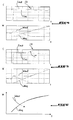
- La figure 1 est un graphique montrant des oscillations de couple et de vitesses de rotation tendant à apparaître au collage d'un embrayage ;
- La figure 2 est une représentation d'éléments de moteur et de transmission modélisés ;
- La figure 3 est un graphique donnant l'évolution des couples et vitesses de rotation sur collage d'un embrayage piloté de l'Etat de la technique ;
- La figure 4 est un graphique donnant l'évolution des couples et vitesses de rotation sur collage d'un embrayage piloté selon l'invention ;
- La figure 5 est un graphique donnant l'évolution des couples et vitesses de rotation sur collage d'un embrayage piloté selon une variante de l'invention ;
- La figure 6 est un graphique donnant l'évolution des vitesses de rotation sur collage d'un embrayage piloté selon une variante de l'invention ;
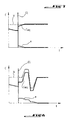
- La figure 7 est un graphique illustrant un rattrapage de l'erreur en couple selon l'invention dans un temps fini ;
- La figure 8 est un graphique illustrant un rattrapage de l'erreur en couple selon l'invention dissimulée lors des variations de consigne du conducteur.
- L'invention s'applique à un embrayage piloté qui est associé à une unité de commande qui agit sur un moteur pour en modifier en temps réel les paramètres de fonctionnement. L'embrayage est piloté en collage soit par cette unité de commande, soit par un dispositif dédié qui est relié à cette unité de commande.
- Cet embrayage est implanté entre un organe rotatif du moteur tel qu'un arbre de sortie du moteur, et un arbre de transmission qui est par exemple un arbre primaire de boîte de vitesses, cette boîte de vitesses entraînant elle-même en rotation des organes de transmission à des roues motrices du véhicule.
- L'unité de commande qui agit sur différents organes du véhicule est notamment reliée à la pédale d'accélérateur du véhicule, pour prendre en compte une valeur de consigne de couple qui correspond sensiblement à l'inclinaison de la pédale d'accélérateur.
- En début de collage, l'embrayage est dans un état glissant dans lequel il transmet un couple mécanique, mais dans lequel les vitesses de rotation de l'arbre primaire et de l'arbre moteur sont différentes. Durant cette phase, l'unité de commande pilote l'embrayage et éventuellement le moteur pour délivrer aux roues motrices un couple Ceq correspondant à la valeur de consigne de couple.
- Selon l'invention, l'unité de commande pilote le moteur pour qu'il génère un créneau de couple au moment, un peu avant, ou un peu après le collage de l'embrayage. Ce créneau de couple qui est une augmentation brutale du couple moteur Cmot, d'amplitude prédéterminée, est représenté en figure 4 en étant repéré par CR. Il a pour effet d'annuler ou de réduire très fortement les oscillations qui tendent à apparaître au collage de l'embrayage.
- Ce créneau a une amplitude qui est déterminée dans l'unité de commande, à partir du moment d'inertie Jmot des éléments rotatifs du moteur, et de la dérivée de la différence entre la vitesse de rotation de l'arbre secondaire Weq et de l'arbre moteur Wmot à un instant t0-précédant le collage de l'embrayage.
- Avantageusement l'amplitude de ce créneau est déterminée dans l'unité de commande avec la relation : CR=Jmot.d(Weq(t0-) - Wmot(t0-))/dt.
- La détermination de l'instant t0 auquel l'embrayage passe de l'état glissant à collé peut être effectuée en temps réel par comparaison des mesures des vitesses de rotation Weq et Wmot. Cet instant de collage peut également être estimé par anticipation, à partir de paramètres de fonctionnement et de commande de l'embrayage, et des régimes mesurés ou estimés du moteur et/ou de l'arbre primaire.
- L'unité de commande est avantageusement conçue pour anticiper le temps de réaction du moteur, de manière à assurer que le créneau CR soit généré à un instant qui est le plus proche possible de l'instant de collage. A cet effet, l'unité de commande peut agir sur le moteur à un instant qui précède le collage effectif de l'embrayage, cet instant étant déterminé sur la base d'une estimation du temps de collage de l'embrayage et d'une estimation du temps de réaction du moteur.
- Dans le cas d'un moteur thermique à allumage commandé, l'unité de commande agit sur ce moteur pour modifier temporairement l'avance d'allumage avant de générer le créneau de couple. L'unité de commande pilote alors le moteur en prenant une garde à l'avance d'allumage, par exemple en début de collage de l'embrayage, puis elle rétablit brutalement l'avance d'allumage normale pour que le moteur génère le créneau de couple.
- La valeur de la garde d'avance à l'allumage est déterminée à partir de caractéristiques du moteur, par exemple dans l'unité de commande, pour correspondre à la valeur de créneau de couple CR à générer conformément à la relation donnée plus haut. Cette garde à l'allumage peut être prise progressivement en fonction de l'état d'ouverture de l'embrayage, c'est à dire de l'écart entre arbre moteur et arbre secondaire dans l'embrayage.
- Si le couple Ceq à délivrer aux roues motrices pendant la phase de glissement est supérieur au couple maximal Cmot qui pourra être délivré par le moteur après collage de l'embrayage, alors la consigne de couple à délivrer aux roues pendant le glissement est diminuée par l'unité de commande. Cette consigne est diminuée jusqu'à une valeur inférieure à la valeur maximale de couple qui pourra être délivrée aux roues après collage, pour assurer que le créneau de couple CR puisse être généré par le moteur après collage.
- Pour assurer que le créneau de couple CR ait une amplitude correspondant à la relation donnée plus haut, l'unité de commande agit sur le moteur pour modifier la vitesse moteur Wmot afin que la dérivée de la différence entre la vitesse d'arbre primaire Weq et du moteur Wmot reste inférieure à une valeur prédéterminée.
- Un exemple de cette situation est illustré en figure 5 dans laquelle l'unité de commande agit sur le moteur pour qu'il augmente graduellement son couple Cmot en fin de glissement, afin d'augmenter sa vitesse Wmot, ce qui est repéré par C+. Dans cette situation, le couple délivré aux roues n'est pas détérioré, puisqu'il répond à une consigne prise en compte par l'organe de couplage.
- Comme représenté en figure 6, la commande selon l'invention permet de fermer l'embrayage tout en assurant que le régime moteur Wmot diminue constamment jusqu'à l'instant du collage, ce qui améliore le confort de conduite. Les commandes connues de l'état de la technique, telles que celle représentée en figure 3 impliquent au contraire une augmentation de la vitesse de rotation du moteur Wmot avant collage de l'embrayage, ce qui nuit à l'agrément de conduite.
- Dans l'exemple qui a été décrit, le créneau CR a une amplitude qui est déterminée à partir de la relation donnée plus haut. Ce créneau CR peut également avoir une amplitude déterminée différemment, cette amplitude étant par exemple forfaitaire, ou dépendante de la charge appliquée au véhicule, ou bien dépendante des dérivées d'une ou plusieurs vitesses de rotation.
- Après collage de l'embrayage et application du créneau CR, le couple Cmot délivré par le moteur est sensiblement différent de la valeur de consigne V donnée par le conducteur du véhicule via la pédale d'accélérateur. Cet écart peut être annulé progressivement avec une fonction de régulation intégrée à l'unité de commande, qui est initiée après application du créneau de couple CR.
- Une telle fonction d'initialisation est représentée schématiquement en figure 7, qui est un graphe comprenant une courbe représentative du couple moteur tel que restitué par les roues motrices, et repéré par Ceq, et une autre courbe, repérée par V représentative de la consigne de couple de l'utilisateur, et correspondant à l'inclinaison de la pédale d'accélérateur.
- Dans l'exemple de la figure 7, la consigne de couple V ne varie pas durant le collage de l'embrayage, de sorte qu'elle est représentée par une droite horizontale. Après collage de l'embrayage, repéré par CL, il existe un écart e entre la consigne de couple et la valeur du couple Ceq délivré aux roues motrices.
- Comme représenté sur cette figure, la commande agit sur le moteur pour qu'il rattrape cet écart de couple e, de façon linéaire, en un temps prédéterminé ou selon une pente prédéterminée et ce, que le conducteur modifie ou ne modifie pas la consigne de couple utiliseur.
- Dans la variante représentée sur la figure 8, lorsque la consigne de couple conducteur V est constante, le couple effectivement délivré aux roues motrices est maintenu constant conformément à la volonté du conducteur de ne pas modifier le couple délivré au roues.
- Comme représenté en figure 8, lorsque le conducteur agit sur la pédale d'accélérateur de sorte qu'il modifie la consigne V du couple à délivrer aux roues, l'écart e est progressivement annulé en modifiant depuis l'unité de commande des valeurs de consigne appliquées au moteur, de façon bornée en valeur ou en dérivée en rapport de la consigne conducteur V ou de sa variation ou de la valeur absolue de sa variation, afin d'éviter que le conducteur ne perçoive ou ne soit perturbé par le rattrapage de l'écart e. Ainsi, la commande de l'utilisateur rejoint progressivement la consigne appliquée au moteur par l'unité de commande.
- Dans l'exemple décrit plus haut, le créneau de couple est généré en modifiant l'avance d'allumage avant d'appliquer le créneau et en la rétablissant pour appliquer le créneau. D'autres solutions peuvent également être envisagées pour générer le créneau de couple.
- Dans le cas d'un moteur à distribution variable, la charge moteur peut être modifiée en faisant varier d'un tour à l'autre du moteur la quantité d'air et de carburant entrant dans la chambre de combustion.
- La variation de couple peut aussi être obtenue par modification de la quantité de carburant injecté dans le cas d'un moteur diesel, ou encore par modification de l'angle d'injection dans le cas d'un moteur diesel suralimenté.
- Ce créneau peut également être obtenu au moyen d'un alternateur lié en rotation avec le moteur, qui est exploité pour dissiper de l'énergie avant de générer le créneau de couple, cette dissipation d'énergie étant alors brutalement interrompue pour produire le créneau de couple. Un frein mécanique peut également être utilisé de manière analogue.
- Ce créneau de couple peut encore également être obtenu au moyen d'un moteur électrique lié en rotation soit avec le moteur thermique, soit avec l'arbre primaire.
Claims (7)
- Procédé pour piloter, depuis une unité de commande, un moteur relié à un arbre primaire par un organe de couplage piloté, lorsque cet organe de couplage est piloté pour passer d'un état glissant dans lequel le moteur et l'arbre primaire ont des vitesses (Wmot, Weq) différentes, à un état collé dans lequel ces vitesses sont identiques, consistant à piloter le moteur pour qu'il génère un créneau de couple (CR) lorsque l'organe de couplage passe à l'état collé.
- Procédé selon la revendication 1, consistant à piloter le moteur pour que le créneau de couple (CR) ait une amplitude correspondant au produit d'une valeur d'inertie (Jmot) du moteur avec une valeur de dérivée par rapport au temps de la différence des vitesses de l'arbre primaire (Weq) et du moteur (Wmot) à un instant précédant le passage à l'état collé.
- Procédé selon la revendication 2, consistant en outre à piloter le moteur avant collage de l'organe de couplage pour augmenter graduellement le couple (Cmot) qu'il génère afin de limiter la valeur de dérivée par rapport au temps de la différence des vitesses de l'arbre primaire (Weq) et du moteur (Wmot).
- Procédé selon l'une des revendications 1 à 3, appliqué à un moteur thermique, consistant à modifier temporairement une valeur d'avance à l'allumage ou une valeur d'angle d'injection de ce moteur avant collage de l'organe de couplage, et à rétablir une valeur d'avance à l'allumage ou d'angle d'injection normale pour générer le créneau de couple (CR).
- Procédé selon l'une des revendications 1 à 4, dans lequel l'unité de commande intègre l'anticipation d'un temps de réponse du moteur pour piloter la génération par le moteur du créneau de couple (CR).
- Procédé selon l'une des revendications 1 à 5, consistant à piloter le moteur pour annuler progressivement l'écart de commande en couple après collage en un certain intervalle de temps prédéterminé ou avec une pente déterminée.
- Procédé selon l'une des revendications 1 à 5, consistant à piloter le moteur pour annuler progressivement l'écart de commande en couple après collage lors et en proportion des variations de consigne conducteur.
Applications Claiming Priority (1)
| Application Number | Priority Date | Filing Date | Title |
|---|---|---|---|
| FR0650321A FR2896750B1 (fr) | 2006-01-30 | 2006-01-30 | Procede de commande d'un groupe motopropulseur de vehicule automobile |
Publications (1)
| Publication Number | Publication Date |
|---|---|
| EP1813794A1 true EP1813794A1 (fr) | 2007-08-01 |
Family
ID=37204626
Family Applications (1)
| Application Number | Title | Priority Date | Filing Date |
|---|---|---|---|
| EP07300748A Withdrawn EP1813794A1 (fr) | 2006-01-30 | 2007-01-26 | Procede de commande d'un groupe motopropulseur de vehicule automobile |
Country Status (2)
| Country | Link |
|---|---|
| EP (1) | EP1813794A1 (fr) |
| FR (1) | FR2896750B1 (fr) |
Cited By (9)
| Publication number | Priority date | Publication date | Assignee | Title |
|---|---|---|---|---|
| US9718457B2 (en) | 2013-09-09 | 2017-08-01 | Byd Company Limited | Hybrid electrical vehicle and method for controlling the same |
| US9902291B2 (en) | 2013-09-09 | 2018-02-27 | Byd Company Limited | Vehicle and sliding feedback control system of vehicle and method for the same |
| EP3287672A1 (fr) * | 2016-08-23 | 2018-02-28 | PSA Automobiles SA | Procede de controle d'un couple moteur d'un vehicule, notamment automobile |
| US10011264B2 (en) | 2013-09-09 | 2018-07-03 | Byd Company Limited | Control system of hybrid electrical vehicle and control method for the same |
| US10017174B2 (en) | 2013-09-09 | 2018-07-10 | Byd Company Limited | Control system and control method of hybrid electric vehicle |
| US10077040B2 (en) | 2013-09-09 | 2018-09-18 | Byd Company Limited | Hybrid electrical vehicle and method for controlling same |
| US10077039B2 (en) | 2013-09-09 | 2018-09-18 | Byd Company Limited | Hybrid electrical vehicle and method for controlling the same |
| US10099690B2 (en) | 2013-09-09 | 2018-10-16 | Byd Company Limited | Hybrid electrical vehicle and method for cruising control of the same |
| FR3106320A1 (fr) * | 2020-01-21 | 2021-07-23 | Renault S.A.S | Procédé de commande d’un véhicule automobile pour éviter les à coups à l’embrayage |
Citations (6)
| Publication number | Priority date | Publication date | Assignee | Title |
|---|---|---|---|---|
| DE10105321A1 (de) * | 2001-02-02 | 2002-08-08 | Daimler Chrysler Ag | Verfahren zum Betrieb eines Antriebsstrangs eines Kraftfahrzeugs |
| GB2386932A (en) * | 2002-03-28 | 2003-10-01 | Luk Lamellen & Kupplungsbau | Method of controlling engine torque during a gear shift |
| EP1371835A2 (fr) * | 2002-06-13 | 2003-12-17 | Bayerische Motoren Werke Aktiengesellschaft | Unité électronique pour le calcul d'une valeur cible du couple moteur pendant la régulation d'un moteur à combustion |
| US20040106498A1 (en) * | 2002-11-30 | 2004-06-03 | Edward Badillo | Method for managing engine torque during a gear shift in an automatic shift manual transmission |
| EP1439087A2 (fr) | 2003-01-16 | 2004-07-21 | Siemens Aktiengesellschaft | Procédé de commande et de régulation du couple moteur et du couple d'embrayage durant un changement de vitesse d'une transmission robotisée ou à double embrayage |
| DE10337624A1 (de) * | 2003-04-10 | 2005-03-10 | Luk Lamellen & Kupplungsbau | Steuereinrichtung und Verfahren zum Ansteuern eines Motormomentes und eines Kupplungsmomentes bei einem Antriebsstrang |
-
2006
- 2006-01-30 FR FR0650321A patent/FR2896750B1/fr not_active Expired - Fee Related
-
2007
- 2007-01-26 EP EP07300748A patent/EP1813794A1/fr not_active Withdrawn
Patent Citations (6)
| Publication number | Priority date | Publication date | Assignee | Title |
|---|---|---|---|---|
| DE10105321A1 (de) * | 2001-02-02 | 2002-08-08 | Daimler Chrysler Ag | Verfahren zum Betrieb eines Antriebsstrangs eines Kraftfahrzeugs |
| GB2386932A (en) * | 2002-03-28 | 2003-10-01 | Luk Lamellen & Kupplungsbau | Method of controlling engine torque during a gear shift |
| EP1371835A2 (fr) * | 2002-06-13 | 2003-12-17 | Bayerische Motoren Werke Aktiengesellschaft | Unité électronique pour le calcul d'une valeur cible du couple moteur pendant la régulation d'un moteur à combustion |
| US20040106498A1 (en) * | 2002-11-30 | 2004-06-03 | Edward Badillo | Method for managing engine torque during a gear shift in an automatic shift manual transmission |
| EP1439087A2 (fr) | 2003-01-16 | 2004-07-21 | Siemens Aktiengesellschaft | Procédé de commande et de régulation du couple moteur et du couple d'embrayage durant un changement de vitesse d'une transmission robotisée ou à double embrayage |
| DE10337624A1 (de) * | 2003-04-10 | 2005-03-10 | Luk Lamellen & Kupplungsbau | Steuereinrichtung und Verfahren zum Ansteuern eines Motormomentes und eines Kupplungsmomentes bei einem Antriebsstrang |
Cited By (10)
| Publication number | Priority date | Publication date | Assignee | Title |
|---|---|---|---|---|
| US9718457B2 (en) | 2013-09-09 | 2017-08-01 | Byd Company Limited | Hybrid electrical vehicle and method for controlling the same |
| US9902291B2 (en) | 2013-09-09 | 2018-02-27 | Byd Company Limited | Vehicle and sliding feedback control system of vehicle and method for the same |
| US10011264B2 (en) | 2013-09-09 | 2018-07-03 | Byd Company Limited | Control system of hybrid electrical vehicle and control method for the same |
| US10017174B2 (en) | 2013-09-09 | 2018-07-10 | Byd Company Limited | Control system and control method of hybrid electric vehicle |
| US10077040B2 (en) | 2013-09-09 | 2018-09-18 | Byd Company Limited | Hybrid electrical vehicle and method for controlling same |
| US10077039B2 (en) | 2013-09-09 | 2018-09-18 | Byd Company Limited | Hybrid electrical vehicle and method for controlling the same |
| US10099690B2 (en) | 2013-09-09 | 2018-10-16 | Byd Company Limited | Hybrid electrical vehicle and method for cruising control of the same |
| EP3287672A1 (fr) * | 2016-08-23 | 2018-02-28 | PSA Automobiles SA | Procede de controle d'un couple moteur d'un vehicule, notamment automobile |
| FR3055283A1 (fr) * | 2016-08-23 | 2018-03-02 | Peugeot Citroen Automobiles Sa | Procede de controle d'un couple moteur d'un vehicule, notamment automobile |
| FR3106320A1 (fr) * | 2020-01-21 | 2021-07-23 | Renault S.A.S | Procédé de commande d’un véhicule automobile pour éviter les à coups à l’embrayage |
Also Published As
| Publication number | Publication date |
|---|---|
| FR2896750B1 (fr) | 2009-11-13 |
| FR2896750A1 (fr) | 2007-08-03 |
Similar Documents
| Publication | Publication Date | Title |
|---|---|---|
| FR2716516A1 (fr) | Procédé pour commander un système de transmission de couple et dispositifs pour sa mise en Óoeuvre. | |
| FR2710123A1 (fr) | Véhicule avec convertisseur hydrodynamique de couple associé à un embrayage de pontage et procédé de commande de ce dernier. | |
| EP1937963A1 (fr) | Procede de demarrage d'un moteur thermique de vehicule hybride | |
| FR2956637A1 (fr) | Procede de gestion d'un systeme d'entrainement pour vehicule automobile | |
| WO2006092522A1 (fr) | Procede de decollage rapide d'un vehicule hybride | |
| FR2815688A1 (fr) | Vehicule a moteur avec boite de vitesses ainsi que procede pour utiliser un vehicule a moteur | |
| FR2524401A1 (fr) | Dispositif de commande d'un mecanisme progressif automatique pour vehicules automobiles | |
| FR2896750A1 (fr) | Procede de commande d'un groupe motopropulseur de vehicule automobile | |
| FR2947789A1 (fr) | Procede de gestion d'un vehicule hybride et installation d'entrainement le mettant en oeuvre | |
| EP2044315A1 (fr) | Procede de gestion d'un couple applique a un arbre de sortie d'un moteur thermique lors d'une desactivation d'une chambre de combustion et systeme de gestion correspondant | |
| FR2825954A1 (fr) | Procede et systeme de commande de la conduite en marche rampante d'un vehicule equipe d'un embrayage automatise | |
| FR2559107A1 (fr) | Circuit de commande de prise directe pour transmission hydraulique d'automobile | |
| WO2016110650A1 (fr) | Procédé de commande d'un moteur thermique de véhicule | |
| FR3021018B1 (fr) | Procede de gestion d'un vehicule automobile | |
| WO2011086252A1 (fr) | Procede et dispositif pour obtenir un decollage a forte charge de vehicules hybrides | |
| EP1896280A2 (fr) | Procede pour piloter le couplage ou le decouplage des deux moteurs d' un groupe motopropulseur hybride parallele | |
| EP1753947A2 (fr) | Procede de controle d'une consigne de couple a appliquer aux roues d'une transmission automatisee pour vehicule automobile et dispositif correspondant. | |
| FR2921138A1 (fr) | Volant d'inertie a deux masses avec un moyen de positionnement. | |
| WO2018087438A1 (fr) | Dispositif et procédé de pilotage d'une boite de vitesses robotisee pour vehicule automobile a propulsion hybride | |
| FR2780002A1 (fr) | Systeme d'entrainement d'un vehicule | |
| EP4097344B1 (fr) | Contrôle du couple moteur à combustion d'un véhicule automobile lors de la fermeture de l'embrayage | |
| FR3100195A1 (fr) | Procédé de détermination d’un régime moteur de décollage pour une amélioration de la prestation acoustique et vibratoire dans les vehicules | |
| EP1846647B1 (fr) | Procede de controle de l'inversion de la puissance dans un systeme comportant un convertisseur de couple et ensemble mecanique integrant ledit procede | |
| EP3083359B1 (fr) | Déconnexion temporaire d'accessoires au décollage d'un véhicule automobile | |
| FR3066167A1 (fr) | Procede de controle d'un groupe motopropulseur d'un vehicule hybride pour le demarrage de ce vehicule |
Legal Events
| Date | Code | Title | Description |
|---|---|---|---|
| PUAI | Public reference made under article 153(3) epc to a published international application that has entered the european phase |
Free format text: ORIGINAL CODE: 0009012 |
|
| AK | Designated contracting states |
Kind code of ref document: A1 Designated state(s): AT BE BG CH CY CZ DE DK EE ES FI FR GB GR HU IE IS IT LI LT LU LV MC NL PL PT RO SE SI SK TR |
|
| AX | Request for extension of the european patent |
Extension state: AL BA HR MK YU |
|
| 17P | Request for examination filed |
Effective date: 20080108 |
|
| 17Q | First examination report despatched |
Effective date: 20080310 |
|
| AKX | Designation fees paid |
Designated state(s): AT BE BG CH CY CZ DE DK EE ES FI FR GB GR HU IE IS IT LI LT LU LV MC NL PL PT RO SE SI SK TR |
|
| STAA | Information on the status of an ep patent application or granted ep patent |
Free format text: STATUS: THE APPLICATION IS DEEMED TO BE WITHDRAWN |
|
| 18D | Application deemed to be withdrawn |
Effective date: 20150801 |