EP1813230A1 - Ensemble d'Instrumentation chirurgicale pour poser une prothèse de cheville - Google Patents
Ensemble d'Instrumentation chirurgicale pour poser une prothèse de cheville Download PDFInfo
- Publication number
- EP1813230A1 EP1813230A1 EP07356007A EP07356007A EP1813230A1 EP 1813230 A1 EP1813230 A1 EP 1813230A1 EP 07356007 A EP07356007 A EP 07356007A EP 07356007 A EP07356007 A EP 07356007A EP 1813230 A1 EP1813230 A1 EP 1813230A1
- Authority
- EP
- European Patent Office
- Prior art keywords
- phantom
- tibial
- pad
- implant
- tibia
- Prior art date
- Legal status (The legal status is an assumption and is not a legal conclusion. Google has not performed a legal analysis and makes no representation as to the accuracy of the status listed.)
- Granted
Links
- 239000007943 implant Substances 0.000 claims abstract description 133
- 210000002303 tibia Anatomy 0.000 claims abstract description 71
- 210000003423 ankle Anatomy 0.000 claims abstract description 60
- 210000004233 talus Anatomy 0.000 claims abstract description 19
- 241001061264 Astragalus Species 0.000 claims description 24
- 235000006533 astragalus Nutrition 0.000 claims description 12
- 230000006399 behavior Effects 0.000 claims description 5
- 230000003100 immobilizing effect Effects 0.000 claims description 3
- 230000000284 resting effect Effects 0.000 claims 1
- 238000012360 testing method Methods 0.000 abstract description 5
- 210000000988 bone and bone Anatomy 0.000 description 20
- 238000000034 method Methods 0.000 description 12
- 238000002360 preparation method Methods 0.000 description 12
- 238000002513 implantation Methods 0.000 description 11
- 210000000544 articulatio talocruralis Anatomy 0.000 description 5
- 238000004873 anchoring Methods 0.000 description 4
- 230000002093 peripheral effect Effects 0.000 description 4
- 101100536354 Drosophila melanogaster tant gene Proteins 0.000 description 3
- 230000000295 complement effect Effects 0.000 description 3
- 238000009434 installation Methods 0.000 description 3
- 239000000463 material Substances 0.000 description 3
- 230000001419 dependent effect Effects 0.000 description 2
- 238000002271 resection Methods 0.000 description 2
- 239000000126 substance Substances 0.000 description 2
- 241001415961 Gaviidae Species 0.000 description 1
- 241001080024 Telles Species 0.000 description 1
- 230000015556 catabolic process Effects 0.000 description 1
- 239000000919 ceramic Substances 0.000 description 1
- 239000011248 coating agent Substances 0.000 description 1
- 238000000576 coating method Methods 0.000 description 1
- 238000006731 degradation reaction Methods 0.000 description 1
- 238000006073 displacement reaction Methods 0.000 description 1
- 210000002683 foot Anatomy 0.000 description 1
- 238000007689 inspection Methods 0.000 description 1
- 210000002414 leg Anatomy 0.000 description 1
- 210000001997 lower extremity of tibia Anatomy 0.000 description 1
- 230000001050 lubricating effect Effects 0.000 description 1
- 230000007170 pathology Effects 0.000 description 1
- 230000002028 premature Effects 0.000 description 1
- 238000003825 pressing Methods 0.000 description 1
- 238000011477 surgical intervention Methods 0.000 description 1
- 238000001356 surgical procedure Methods 0.000 description 1
Images


Classifications
-
- A—HUMAN NECESSITIES
- A61—MEDICAL OR VETERINARY SCIENCE; HYGIENE
- A61B—DIAGNOSIS; SURGERY; IDENTIFICATION
- A61B17/00—Surgical instruments, devices or methods, e.g. tourniquets
- A61B17/14—Surgical saws ; Accessories therefor
- A61B17/15—Guides therefor
-
- A—HUMAN NECESSITIES
- A61—MEDICAL OR VETERINARY SCIENCE; HYGIENE
- A61F—FILTERS IMPLANTABLE INTO BLOOD VESSELS; PROSTHESES; DEVICES PROVIDING PATENCY TO, OR PREVENTING COLLAPSING OF, TUBULAR STRUCTURES OF THE BODY, e.g. STENTS; ORTHOPAEDIC, NURSING OR CONTRACEPTIVE DEVICES; FOMENTATION; TREATMENT OR PROTECTION OF EYES OR EARS; BANDAGES, DRESSINGS OR ABSORBENT PADS; FIRST-AID KITS
- A61F2/00—Filters implantable into blood vessels; Prostheses, i.e. artificial substitutes or replacements for parts of the body; Appliances for connecting them with the body; Devices providing patency to, or preventing collapsing of, tubular structures of the body, e.g. stents
- A61F2/02—Prostheses implantable into the body
- A61F2/30—Joints
- A61F2/42—Joints for wrists or ankles; for hands, e.g. fingers; for feet, e.g. toes
- A61F2/4202—Joints for wrists or ankles; for hands, e.g. fingers; for feet, e.g. toes for ankles
-
- A—HUMAN NECESSITIES
- A61—MEDICAL OR VETERINARY SCIENCE; HYGIENE
- A61F—FILTERS IMPLANTABLE INTO BLOOD VESSELS; PROSTHESES; DEVICES PROVIDING PATENCY TO, OR PREVENTING COLLAPSING OF, TUBULAR STRUCTURES OF THE BODY, e.g. STENTS; ORTHOPAEDIC, NURSING OR CONTRACEPTIVE DEVICES; FOMENTATION; TREATMENT OR PROTECTION OF EYES OR EARS; BANDAGES, DRESSINGS OR ABSORBENT PADS; FIRST-AID KITS
- A61F2/00—Filters implantable into blood vessels; Prostheses, i.e. artificial substitutes or replacements for parts of the body; Appliances for connecting them with the body; Devices providing patency to, or preventing collapsing of, tubular structures of the body, e.g. stents
- A61F2/02—Prostheses implantable into the body
- A61F2/30—Joints
- A61F2/46—Special tools or methods for implanting or extracting artificial joints, accessories, bone grafts or substitutes, or particular adaptations therefor
- A61F2/4603—Special tools or methods for implanting or extracting artificial joints, accessories, bone grafts or substitutes, or particular adaptations therefor for insertion or extraction of endoprosthetic joints or of accessories thereof
- A61F2/4606—Special tools or methods for implanting or extracting artificial joints, accessories, bone grafts or substitutes, or particular adaptations therefor for insertion or extraction of endoprosthetic joints or of accessories thereof of wrists or ankles; of hands, e.g. fingers; of feet, e.g. toes
-
- A—HUMAN NECESSITIES
- A61—MEDICAL OR VETERINARY SCIENCE; HYGIENE
- A61F—FILTERS IMPLANTABLE INTO BLOOD VESSELS; PROSTHESES; DEVICES PROVIDING PATENCY TO, OR PREVENTING COLLAPSING OF, TUBULAR STRUCTURES OF THE BODY, e.g. STENTS; ORTHOPAEDIC, NURSING OR CONTRACEPTIVE DEVICES; FOMENTATION; TREATMENT OR PROTECTION OF EYES OR EARS; BANDAGES, DRESSINGS OR ABSORBENT PADS; FIRST-AID KITS
- A61F2/00—Filters implantable into blood vessels; Prostheses, i.e. artificial substitutes or replacements for parts of the body; Appliances for connecting them with the body; Devices providing patency to, or preventing collapsing of, tubular structures of the body, e.g. stents
- A61F2/02—Prostheses implantable into the body
- A61F2/30—Joints
- A61F2/46—Special tools or methods for implanting or extracting artificial joints, accessories, bone grafts or substitutes, or particular adaptations therefor
- A61F2/4684—Trial or dummy prostheses
-
- A—HUMAN NECESSITIES
- A61—MEDICAL OR VETERINARY SCIENCE; HYGIENE
- A61F—FILTERS IMPLANTABLE INTO BLOOD VESSELS; PROSTHESES; DEVICES PROVIDING PATENCY TO, OR PREVENTING COLLAPSING OF, TUBULAR STRUCTURES OF THE BODY, e.g. STENTS; ORTHOPAEDIC, NURSING OR CONTRACEPTIVE DEVICES; FOMENTATION; TREATMENT OR PROTECTION OF EYES OR EARS; BANDAGES, DRESSINGS OR ABSORBENT PADS; FIRST-AID KITS
- A61F2/00—Filters implantable into blood vessels; Prostheses, i.e. artificial substitutes or replacements for parts of the body; Appliances for connecting them with the body; Devices providing patency to, or preventing collapsing of, tubular structures of the body, e.g. stents
- A61F2/02—Prostheses implantable into the body
- A61F2/30—Joints
- A61F2/46—Special tools or methods for implanting or extracting artificial joints, accessories, bone grafts or substitutes, or particular adaptations therefor
- A61F2/4603—Special tools or methods for implanting or extracting artificial joints, accessories, bone grafts or substitutes, or particular adaptations therefor for insertion or extraction of endoprosthetic joints or of accessories thereof
- A61F2002/4622—Special tools or methods for implanting or extracting artificial joints, accessories, bone grafts or substitutes, or particular adaptations therefor for insertion or extraction of endoprosthetic joints or of accessories thereof having the shape of a forceps or a clamp
-
- A—HUMAN NECESSITIES
- A61—MEDICAL OR VETERINARY SCIENCE; HYGIENE
- A61F—FILTERS IMPLANTABLE INTO BLOOD VESSELS; PROSTHESES; DEVICES PROVIDING PATENCY TO, OR PREVENTING COLLAPSING OF, TUBULAR STRUCTURES OF THE BODY, e.g. STENTS; ORTHOPAEDIC, NURSING OR CONTRACEPTIVE DEVICES; FOMENTATION; TREATMENT OR PROTECTION OF EYES OR EARS; BANDAGES, DRESSINGS OR ABSORBENT PADS; FIRST-AID KITS
- A61F2/00—Filters implantable into blood vessels; Prostheses, i.e. artificial substitutes or replacements for parts of the body; Appliances for connecting them with the body; Devices providing patency to, or preventing collapsing of, tubular structures of the body, e.g. stents
- A61F2/02—Prostheses implantable into the body
- A61F2/30—Joints
- A61F2/46—Special tools or methods for implanting or extracting artificial joints, accessories, bone grafts or substitutes, or particular adaptations therefor
- A61F2/4603—Special tools or methods for implanting or extracting artificial joints, accessories, bone grafts or substitutes, or particular adaptations therefor for insertion or extraction of endoprosthetic joints or of accessories thereof
- A61F2002/4625—Special tools or methods for implanting or extracting artificial joints, accessories, bone grafts or substitutes, or particular adaptations therefor for insertion or extraction of endoprosthetic joints or of accessories thereof with relative movement between parts of the instrument during use
- A61F2002/4628—Special tools or methods for implanting or extracting artificial joints, accessories, bone grafts or substitutes, or particular adaptations therefor for insertion or extraction of endoprosthetic joints or of accessories thereof with relative movement between parts of the instrument during use with linear motion along or rotating motion about an axis transverse to the instrument axis or to the implantation direction, e.g. clamping
Definitions
- the present invention relates to a surgical instrumentation set for an ankle prosthesis, as well as a surgical method for fitting such a prosthesis.
- An ankle prosthesis mainly comprises a tibial implant, an astragalian implant and a prosthetic pad interposed between the tibial and astragalian implants.
- This skate is qualified as "mobile” when it is assembled to the tibial and astragalian implants by being mobile with respect to each of these implants, while it is described as “fixed” when, while being mobile with respect to the Astragalian implant, it is fixedly attached to the tibial implant.
- an ankle prosthesis whether with a movable tray or a fixed plateau, at the level of the ankle of a patient requires, during an operation by an anterior approach, to prepare, in particular by resections, the lower end of the tibia and the superior end of the patient's talus, to fix permanently the tibial and astragalian implants.
- the surgeon frequently uses ghosts of the prosthetic implants, allowing him to make sure that these preparations are suitable and that additional bone clearances or additional resurfacing are not necessary.
- the surgeon sets up, at the ankle of the patient, a phantom of the talar implant, immobilized on the resected end of the talus, a phantom of the tibial implant, immobilized while being pressed against the resected end of the tibia, and a phantom pad of the prosthetic pad, interposed between the phantoms of the talar and tibial implants while being movable with respect to each of these implant phantoms.
- the surgeon has several ghost pads of different respective thicknesses, each of these ghost pads corresponding to a prosthetic pad that can be subsequently implanted, and thus chooses the ghost pad thickest most appropriate.
- the thickness of the pad to actually implement that is to say its size globally vertical, varies so that the surgeon has, in practice, a series of several prosthetic pads which each have substantially the same surfaces of movable or fixed connection with the talar and talar implants, but whose respective thicknesses are 4, 5 , 6 and 7 mm for example.
- the surgeon After putting in place the aforementioned phantom components, the surgeon solicits the ankle joint of the patient, in particular following flexion-extension movements. He then controls, intraoperatively, the quality of the bone preparations, as well as the dynamic behavior of the ankle provided with the ghost components, which is representative of that of the ankle subsequently provided with the prosthetic components to be implanted.
- ankle prostheses Despite the structural qualities of ankle prostheses, the clinical experience shows that they are quite frequently implanted unsatisfactorily: when it is a prosthesis fixed shoe, significant overconstraints are found in service between the pad and the tibial implant, which leads, more or less short term, to a rupture of the fixed connection zone between the implant and the pad or damage to the tibia bone end; when it comes to a mobile shoe prosthesis, which one tends to use precisely in order to circumvent the aforementioned disadvantage of fixed-slip prostheses, it is found that, in use, the upper surface of the prosthetic pad extends, more or less widely, outside the peripheral contour of the lower surface of the tibial implant, so that the parts of these surfaces in moving contact are narrower than expected, leading to premature wear of the pad and / or the implant. In other words, the currently used laying methods do not guarantee an effective relative implantation position between the tibial implant and the prosthetic pad, whether the latter is fixed or mobile, no possibility of reliable correction being offered to
- the object of the present invention is to provide a surgical intervention assembly for placing a fixed or movable fixed ankle prosthesis, which allows the surgeon to ensure satisfactory relative implantation positioning between the tibial implant and the prosthetic foot. the prosthesis so that this prosthesis does not undergo an early degradation in service.
- the subject of the invention is a set of surgical instrumentation for fitting an ankle prosthesis, the prosthesis including a tibial implant, an astragalian implant and a prosthetic pad interposed between the tibial and astragalian implants, this instrumentation assembly.
- this instrumentation assembly comprising a tibial implant tibial phantom, an astragalian astragalian implant phantom and a phantom skate of the prosthetic pad, adapted to be jointly solicited at the ankle of an operated patient, for control purposes and intraoperative tests, characterized in that the tibial phantom is adapted to be both fixedly attached to the phantom pad and freely movable against a lower end of the patient's tibia.
- the surgeon puts in place, at the level of the ankle of the patient previously prepared and before finally implanting the prosthesis, the tibial phantom, the astragalian phantom and the phantom pad of the instrumentation assembly according to the invention. He then applies, always intraoperatively, the ankle joint of the patient, in particular to ensure that the bone preparations are satisfactory and the size of the prosthetic pad to be implanted, as well as possibly those of the tibial implant and / or or astragalian implant, are appropriate.
- the tibial implant will be implanted so that the implanted prosthetic pad is placed in a predetermined manner vis-à-vis the tibial implant.
- the implanted prosthetic pad is either of the fixed type or of the movable type, it is therefore understood that by making sure that the tibial phantom and the phantom pad are fixedly connected to one another according to the same configuration as the fixed assembly of the tibial implant and prosthetic pad subsequently implanted, so that the phantom pad is generally centered on the lower surface of the tibial phantom, the implanted prosthetic pad will also be assembled without over-stressing the tibial implant, either globally centered on the lower surface of the tibial implant, provided that the tibial implant is subsequently implanted on the tibia in the aforementioned position.
- this last is advantageously adapted to present kinematic behaviors, vis-à-vis the phantom shoe and astragal of the patient, at least in part similar to those of the talar implant vis-à-vis the prosthetic pad and the Astragalus of the patient.
- the phantom pad s' articulates against the astragalian phantom at least in part following the same kinematics as between the implant and the prosthetic implant subsequently implanted.
- the implantation position of the tibial implant obtained by the surgeon as explained above, takes into account the implantation position of the talar implant of the prosthesis.
- the articular surfaces of the astragalian phantom and the phantom pad are conjugated to one another in horizontal section.
- no mediolateral deflection between the phantom and astragalian phantoms during the intraoperative solicitation of the phantom components at the patient's ankle which avoids disrupting the relative medio-lateral positioning between the lower extremity of the tibia and the sub- together consisting of the phantom shoe and the tibial phantom fixed to each other.
- the method according to the invention allows the surgeon to determine a satisfactory position for implanting the tibial implant in the sense that this implantation position guarantees a predetermined cooperation between the tibial implant and the prosthetic pad subsequently implanted: in the case of a fixed prosthetic pad, this cooperation corresponds to a fixed link without over-stressing; in the case of a mobile prosthetic pad, this cooperation corresponds to a movable connection generally centered on the lower face of the tibial implant.
- FIGS. 1 to 3 show an example of a so-called “sliding shoe” ankle prosthesis.
- This prosthesis comprises three distinct components to be implanted at the level of the articulation of a right ankle of a human being, namely a tibial implant 10, an astragalian implant 20 and a prosthetic pad 30.
- a tibial implant 10 a tibial implant 10
- an astragalian implant 20 a prosthetic pad 30.
- the following description is oriented relative to the bones of an ankle in their anatomical position, that is to say that the terms “posterior” or “back”, “anterior” or “before”, “right”, “left”, “ superior “,” lower “, etc. refer to the ankle of a patient standing on a substantially horizontal surface.
- the term “sagittal” corresponds to a direction in the anterior-posterior direction, vertically on the median line of the ankle, while the term “medial” corresponds to a direction substantially perpendicular to the sagittal plane of the ankle, directed towards the patient's other ankle, the term “lateral” corresponding to a direction in the opposite direction.
- the tibial implant 10 comprises a plate 11 to be fixed at the lower end of the right tibia of the patient, after a suitable preparation of this end.
- the plate 11 is, on its upper side 11A, made of material, by a sagittal wing 12, with a hollow stud bone anchor 13 having a generally cylindrical outer shape with a circular base of axis 13A extending in a generally anteroposterior direction.
- Other bone anchoring means of the plate 11 can be envisaged as long as they effectively immobilize the tibial implant at the lower end of the tibia.
- the plate 11 On its medial side, the plate 11 is provided with a rim 14 extending downwards in a generally vertical plane and able to bear, at least partially, against the medial malleolus of the tibia, by the interior of this malleolus. On its lower side, the plate 11 delimits a flat surface 11B intended to form a sliding support for the flat upper surface 30A of the pad 30.
- the astragalian implant 20 comprises a main block 21 to be fixed to the upper end of the patient's right astragalus, by a hollow stud 22 or any other suitable means extending downwardly from the lower side 21B of the block 21
- the block 21 delimits an articular surface 21A intended to cooperate with a conjugate articular surface 30B delimited on the lower side of the pad 30.
- the surface 21A has an arcuate profile of concavity facing downwards, as shown in Figure 2.
- the articular surfaces 21A and 30B are adapted to slide against each other along this curved profile, as indicated by the arrow F 1 in Figure 2.
- the surface 21A delimits a central convex zone 21A 1 of sliding support for a concave concave zone 30B 1 of the surface 30A of the pad, and on either side of this zone 21A 1 , medial concave zones.
- 21A 2 and lateral 21A 3 along which can be supported and slide conjugate concave zones 30B 1 and 30B 2 of the surface 30B.
- the central zone 30B 1 is narrower than the zone 21A 1 central so as to provide a mediolateral game determined between the zones that connect these central areas and the medial zones 21A 2 , 30B 2 and lateral 21A 3 , 30B 3 .
- the above game allows a mediolateral movement between the implant 20 and the pad 30, as indicated by the arrow F 2 in Figure 3.
- the prosthesis 1 provides a kinematics very close to that of the natural articulation of the ankle since the pad 30 is movable, both with respect to the tibial implant 10, in sliding plane / plane support, and with respect to the astragalian implant 20, according to the movements F 1 and F 2 which can be combined.
- a surgical method for implanting the ankle prosthesis 1 of FIGS. 1 to 3 will be described below, it being understood that the prosthesis in question is only an illustrative, non-limiting example of the method and surgical instruments used to implant this prosthesis.
- prosthesis the method and instruments detailed below can be used to implant ankle prostheses of very diverse structures, for example whose tibial and / or astragalian implants consist of several parts assembled to each other, of a metallic nature. , plastic and / or ceramic.
- the method and instruments according to the invention can be further used to implant a fixed-slip ankle prosthesis.
- the bones of the right ankle of the patient should be prepared.
- the surgeon uses a first cutting block 40, shown very schematically in FIG. 4, which he immobilizes on the patient's tibia T by means of a pin 50 introduced into the tibia in a generally anterolateral direction. -postérieure.
- Block 40 defines a slot 42 for passage of a bone cutting means, in which the surgeon introduces and guides, for example, a cutting blade, so as to resect the lower end of the tibia T, along a cut line indicated in dashed lines in figure 4.
- the block 40 also defines a bore 44 for passing a pin 52.
- This bore 44 is positioned so that the pin 52 is anchored in the astragal A of the patient.
- the cutting block 40 is then removed, while leaving in place the pin 52, around which a second cutting block 60 is then threaded, as shown in Figure 5.
- This block 60 is intended to allow the bone preparation of the
- the block 60 delimits in particular a slot 62 for passing a bone cutting means, in which the surgeon introduces and guides a blade so as to resect the upper end of the astragal A, as indicated by the dotted lines in FIG.
- the resected end A 1 of the astragal A includes several section planes, namely the two main planes shown in Figure 5, as well as an external chamfer and an internal chamfer (not visible).
- a tubular recess A 2 is hollowed in a generally vertical direction, for example by means of a bell-shaped mill.
- the holes left by the pins 50 and 52 are respectively referenced T 2 and A 3 .
- the preparation of the ends of the tibia and astragal includes resurfacing steps of these ends if necessary.
- an instrumentation assembly 100 shown alone in FIGS. 7 and 8. comprises three distinct ghost components, namely a tibial phantom 110, an astragalian phantom 120 and a phantom pad 130.
- the component 110 is a phantom of the tibial implant 10. It comprises a main plate 111 delimiting a flat upper surface 111A which has a peripheral contour geometrically similar to that of the plate 11 of the implant 10 and which is provided, on its medial side, a rim 114 similar to the flange 14 of the implant 10. On its lower side, the plate 111 has a flat surface 111B from which extends downwards, in the central zone of this surface, a bulge 116 in disc shape, come from matter with the rest of the plate.
- the central axis 116 1 of this disk extends perpendicularly to the plate 111, that is to say in a direction generally vertical, and is located substantially in the median vertical plane P 110 of this plate, which corresponds to the plane VIII indicated in Figure 7.
- the plate 111 On its anterior side, the plate 111 is extended forward by a horizontal leg 117 from where extends vertically upwardly a fin 118.
- Three bores pass through this fin in an anteroposterior direction, namely an upper bore 118 1 of longitudinal axis 118 2 , and two lower bores 118 3 of smaller diameter than that of the bore 118 1 .
- the upper end of the fin 118 has a generally cylindrical outer surface 119 with a circular base, centered around the axis 118 2 .
- the axis 118 2 and the respective longitudinal axes of the lower bores 118 3 are co-planar and situated substantially in the plane P 110 .
- the component 130 is a phantom of the prosthetic pad 30. It has, on its upper side, a flat surface 130A in the central zone of which is formed, downwards, a circular cylindrical cavity 131.
- This cavity 131 is complementary to the disc bulge 116 of the tibial phantom 110 so that when the phantom pad and the tibial phantom are assembled to each other as in Figure 9, the bulge 116 is housed in the cavity 131.
- an eccentric pin 119 extends projecting downwards from the bulge 116, to be received in a complementary housing 132 dug in the phantom pad 130, in the bottom of the cavity 131, as indicated by the arrow F 3 in Figure 8.
- the cooperation of the pin 119 and its housing 132 also aims to angularly index the tibial phantom 110 and the phantom pad 130 so that the The median vertical planes of these components are substantially merged along plane P 110 , as shown in Figure 9.
- the phantom shoe 130 defines an articular surface 130B similar to the lower articular surface 30B of the prosthetic pad 30.
- a block 121 of the component 120 which is a phantom of the astragalian implant 20, delimits, on its upper side, an articular surface 121A similar to the articular surface 21A of the block 21 of the implant 20.
- the block 121 of the astragalian phantom 120 is provided with a hollow bone anchoring stud 122, similar to the stud 22 of the astragalian implant 20.
- instrumentation assembly 100 The use of the instrumentation assembly 100 is as follows:
- the surgeon first sets up the astragalian phantom 120, immobilizing its pad 122 in the astragalian recess A 2 .
- the astragalian phantom then occupies, vis-à-vis the astragalus A and the tibia T, the same position that will later occupy the astragalian implant 20 to implement.
- the surgeon then assembles the tibial phantom 110 and the phantom pad 130, housing the bulge 116 in the cavity 131, so as to form a phantom subset in one piece, no freedom of movement being allowed between the phantom tibial and phantom skate.
- This phantom subset is placed at the level of the patient's ankle, being introduced between the flat resected end T 1 of the tibia T and the upper articular surface 120 B of the astragalian phantom 120.
- the surgeon then solicits the ankle joint of the patient, in particular following flexion-extension movements.
- the astragalian phantom 120 remains fixed at the upper end of the astragalus A whereas the subassembly consisting of the tibial phantom 110 and the phantom pad 130 is, while being pressed against the resected end T 1 of the tibia, freely driven. moving relative to the astragalian phantom, by cooperation of the articular surfaces 130B and 121A, that is to say according to relative movements similar to the movements F 1 and F 2 , preferably similar to the movement F 1 only, described FIG. 2 and 3.
- the aforementioned phantom subset positions itself, with respect to the astragalian phantom, automatically so that the allowable deflections between the surfaces 130B and 121A are maximal, in view to guarantee similar displacements for prosthetic components subsequently implanted in place of the ghost components.
- the ability of the phantom subset to position itself in this way is related to the freedom of movement allowed between the tibial phantom 110 and the tibia T, by the plane sliding support between the upper surface 111A of the plate 111 of this phantom and the end lower planar resected T 1 of the tibia.
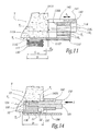
- the set 100, the tibia T and the astragal A are then in the configuration of FIGS. 9 to 11.
- the tibial phantom 110 is then displaced against the tibial end T 1 so that, for example, its median plane P 110 is inclined with respect to the sagittal plane T 3 of the tibia T, under a angle ⁇ non-zero in horizontal section as in Figure 10.
- the anterior zone of the tibia at which opens then the bore 118 1 of the tibial phantom is referenced T 4 .
- the plate 111 of the tibial phantom 110 is then more or less displaced rearwardly with respect to the end T 1 of the tibia T.
- the depth p of the positioning of this plate which corresponds to for example, at the sagittal distance separating its posterior edge 111C from the anterior face of the tibial zone T 4 , is not necessarily equal to the sagittal dimension d 111 of the plate 111, that is to say at the distance between 111C and 111D posterior edges of this plate.
- this depth p is greater than the dimension d 111 , of a value denoted ⁇ p .
- the instrumentation assembly 100 advantageously includes a sleeve 140 adapted to be reported slidably on the upper end portion of the fin 118.
- the bushing 140 thus has, for example, a hollow tubular main body 141, the inner wall of which is complementary to the surface 119 of the upper end of the fin. This body can thus slide, along the axis 118 2 , along this surface 119, as indicated by the arrow F 4 , until its posterior edge 141A abuts against the anterior face of the tibial zone T 4 , as shown in Figure 11.
- the body 141 On its upper side, the body 141 defines an anteroposterior slot 142 along which are provided graduations, for example every two millimeters.
- the graduation "0" of the body 141 abuts against the tibial zone T 4 extends substantially to the perpendicular to the edge 118A of the fin when the edge 111D extends flush with the anterior face of the tibial zone T 4 , that is to say when the aforesaid withdrawal ⁇ p is substantially zero, whereas the value the rearward withdrawal ⁇ p of the edge 111D with respect to this anterior face of the zone T 4 is, as the case may be, measured by reading the graduation extending in line with the edge 118A of the 118.
- the graduation read in this way is the graduation "2", which indicates to the surgeon that the rearward withdrawal ⁇ p tibial phan
- the surgeon After urging the patient's ankle joint while the phantom components 110, 120 and 130 are placed therein as described above, the surgeon has reliable information as to the precise position of the tibial phantom 110 against the resected end. T 1 of the tibia T. This position is satisfactory or optimal from the point of view of the further dynamic behavior of the implanted prosthesis 1, in the sense that it ensures that, taking into account the implantation position of the implant Astralagalien, the later implanted pad 30 will be located opposite the central zone of the lower surface 11B of the tibial implant 10 provided that the latter is implanted in the aforementioned determined position.
- the surgeon uses the bore 118 1 of the tibial phantom 110 to guide the forest of a drill or the like tool in the tibial zone T 4 .
- the surgeon thus digs the zone T 4 along the axis 118 2 of the bore 118 1 , the corresponding piercing, indicated in dotted lines in FIG. 11 and referenced T 5 , being made with the angle ⁇ with respect to the sagittal plane T. 3 of the tibia T and with the frontal shift ⁇ ⁇ at the anterior surface of the tibia.
- the piercing T 5 is intended to receive the bone anchoring pad 13 of the tibial implant 10 so that the diameter of the bore 118 1 is advantageously equal to the outer diameter of the stud 13.
- the lower bores 118 3 of the fin 118 are then advantageously used to release at least a portion of the bone material from the tibial zone T 4 , to subsequently allow the passage of the wing 12 of the implant 10 from the front.
- the ghost components 110, 120 and 130 are released from the ankle to be replaced by the final prosthetic components, namely the tibial implant 10, the talar implant 20 and the prosthetic pad 30.
- the astragalian implant is placed in place of the astragalian phantom 120.
- this ancillary 150 comprises a main impaction rod 151 provided, at its proximal end, with a head 152 for applying the impaction forces and, at its distal end, with a stud 153 able to be threaded into the bore central to the pad 13 of the implant 10, as shown in Figures 13 and 14.
- the ancillary 150 includes a branch 154 of clamping the implant, articulated on the stem 151 in the manner of a clamp, about a transverse axis 155.
- this branch is provided with a plate 156 bearing against the lower planar surface 11B of the implant 10.
- the plate 156 is brought pressing against the 11B of the plate 11, by tilting the branch 154 about the axis 155, so as to firmly tighten the implant 10 between the pin and the plate.
- the surgeon positions it at the level of the tibial zone T 4 and, by applying an impaction force I on the head 152, it forces the stud anchoring 13 in the tibial piercing T 5 .
- this piercing has been performed taking into account the angle ⁇ and the offset ⁇ ⁇
- the implantation of the implant 10 is carried out so that the central axis 13A of its stud 13 occupies substantially the same position, relative to the tibia T, occupied by the axis 118 2 of the bore 118 1 of the tibial phantom 110 after the loading of the ankle with the ghost components.
- the ancillary 150 is also adapted to allow the surgeon to implant the tibial implant 10 with a sagittal depth substantially identical to the depth p occupied by the tibial phantom 110.
- the ancillary is associated with an insert 160 adapted to be removably attached around a distal portion 157 of the rod 151, stepped with respect to both the pin 153 and the remainder of the rod 151.
- This insert is in the form of a tube hollow whose inner diameter is substantially equal to the outer diameter of the rod portion 157 and whose distal edge 160A is intended to abut against the anterior surface of the tibia, around the digging T 5 receiving the tibial anchor pad 13, when the depth p is reached.
- the longitudinal dimension of the insert 160 is related to the value ⁇ p measured with the tibial phantom 110 since the abutment of the edge 160A against the anterior face of the tibial zone T 4 conditions the sagittal depth of impaction of the implant 10, as shown in Figure 14.
- the surgeon has at least as many inserts of different lengths that there are graduations on the sleeve 140, each insert corresponding to each graduation so that the impaction depth of the tibial implant 10 corresponds to the depth p measured by this sleeve.
- the prosthetic pad 30 is attached between this tibial implant and the talar implant 20, being automatically centered against the surface 11B of the tibial implant 10. It is also understood that if the method and the instrumentation set 100 are used to implant a fixed-shoe prosthesis, no over-stress, linked for example to a decentering or a shear, is then generated at the fixed connection zone between the tibial implant and the skate of this prosthesis: the implantation position of the tibial implant at the tibial end is precisely determined by taking into account this fixed connection within the ankle joint, in particular with respect to the astragalian implant, since the tibial phantom 110 and the phantom pad 130 are biased at the ankle, provided with the astragalian phantom 120, being fixedly attached to each other.
- the use of the ghost components 110, 120 and 130 have other advantages than those described above. In particular, they make it possible to ensure that the bone preparations of the lower end of the tibia T and of the upper end of the astragalus A are satisfactory with a view to implanting the ankle prosthesis. Furthermore, as explained above, the use of these ghost components can make it possible to choose the size of the prosthetic pad most appropriate to the operated ankle, the surgeon then having several ghost pads similar to the ghost pad 130, having respective thicknesses. different, for example 4, 5, 6 and 7 mm. Similarly, several tibial and / or astragalian phantoms, with respective different sizes, can be made available to the surgeon so that the latter selects the size of the implanted implants most appropriate to the patient. We then understand the interest of being able to assemble and immobilize the phantom pad 130 of any size with the tibial phantom 110 also of any size.
- the instrumentation assembly according to the invention can include, in addition to ghost components used for the implantation of a right ankle prosthesis such as the prosthesis 1, ghost components intended to pose a left ankle prosthesis, whether it is with a sliding shoe or with a fixed shoe.
- the tibial and astragalian phantoms used to pose a left ankle prosthesis are obtained, from a geometric point of view, by symmetry of the ghost components 110 and 120 described above with respect to their respective median vertical plane.
- the same ghost pad 130 can be used provided that it is turned 180 ° around the vertical before being assembled to the tibial phantom.
- the tibial phantom used to place a left ankle prosthesis then has its pin 119 'diametrically opposed to the pin 119 of the tibial phantom 110 used to place a right ankle prosthesis, as indicated in dashed lines in FIG. 8.
- the housing 132 for receiving the pin 119 or the pin 119 ' is used to undo the assembly of the tibial phantom with the phantom pad depending on whether the prosthesis to be installed is a right or left ankle prosthesis.
Abstract
Description
- La présente invention concerne un ensemble d'instrumention chirurgicale pour poser une prothèse de cheville, ainsi qu'un procédé chirurgical de pose d'une telle prothèse.
- Une prothèse de cheville comprend principalement un implant tibial, un implant astragalien et un patin prothétique interposé entre les implants tibial et astragalien. Ce patin est qualifié de « mobile » lorsqu'il est assemblé aux implants tibial et astragalien en étant mobile par rapport à chacun de ces implants, tandis qu'il est qualifié de « fixe » lorsque, tout en étant mobile par rapport à l'implant astragalien, il est rapporté fixement à l'implant tibial.
- La mise en place d'une prothèse de cheville, qu'elle soit à plateau mobile ou à plateau fixe, au niveau de la cheville d'un patient nécessite, lors d'une intervention chirurgicale par voie d'abord antérieure, de préparer, notamment par des résections, l'extrémité inférieure du tibia et l'extrémité supérieure de l'astragale du patient, pour y fixer à demeure les implants tibial et astragalien. En pratique, une fois que ces préparations osseuses sont effectuées, le chirurgien a fréquemment recours à des fantômes des implants prothétiques, lui permettant de s'assurer que ces préparations sont convenables et que des dégagements osseux supplémentaires ou des resurfaçages additionnels ne sont pas nécessaires.
- Ainsi, le chirurgien met en place, au niveau de la cheville du patient, un fantôme de l'implant astragalien, immobilisé sur l'extrémité réséquée de l'astragale, un fantôme de l'implant tibial, immobilisé en étant plaqué contre l'extrémité réséquée du tibia, et un patin fantôme du patin prothétique, interposé entre les fantômes des implants astragalien et tibial en étant mobile par rapport à chacun de ces fantômes d'implants. En fait, le chirurgien dispose de plusieurs patins fantômes d'épaisseurs respectives différentes, chacun de ces patins fantômes correspondant à un patin prothétique pouvant être ultérieurement implanté, et choisit donc le patin fantôme d'épaisseur la plus appropriée. En effet, en fonction de la morphologie du patient, de la pathologie nécessitant la mise en place de la prothèse et/ou du positionnement relatif des résections effectuées, l'épaisseur du patin à effectivement implanter, c'est-à-dire sa dimension globalement verticale, varie de sorte que le chirurgien dispose, en pratique, d'une série de plusieurs patins prothétiques qui présentent chacun sensiblement les mêmes surfaces de liaison mobile ou fixe avec les implant astragalien et tibial, mais dont les épaisseurs respectives valent 4, 5, 6 et 7 mm par exemple.
- Après avoir mis en place les composants fantômes précités, le chirurgien sollicite l'articulation de cheville du patient, notamment suivant des mouvements de flexion-extension. Il contrôle alors, en peropératoire, la qualité des préparations osseuses, ainsi que le comportement dynamique de la cheville munie des composants fantômes, qui est représentatif de celui de la cheville ultérieurement munie des composants prothétiques à implanter.
- Malgré les qualités structurelles des prothèses de cheville, le recul clinique montre qu'elles sont assez fréquemment implantées de manière insatisfaisante : lorsqu'il s'agit d'une prothèse à patin fixe, des surcontraintes significatives sont constatées en service entre le patin et l'implant tibial, ce qui conduit, à plus ou moins court terme, à une rupture de la zone de liaison fixe entre cet implant et le patin ou à un endommagement de l'extrémité osseuse du tibia ; lorsqu'il s'agit d'une prothèse à patin mobile, que l'on a tendance à utiliser justement pour contourner l'inconvénient précité des prothèses à patin fixe, on constate que, en service, la surface supérieure du patin prothétique s'étend, plus ou moins largement, en dehors du contour périphérique de la surface inférieure de l'implant tibial, de sorte que les parties de ces surfaces en contact mobile sont plus restreintes que prévu, conduisant à une usure prématurée du patin et/ou de l'implant. Autrement dit, les méthodes de pose actuellement employées ne garantissent pas un positionnement d'implantation relatif efficace entre l'implant tibial et le patin prothétique, que ce dernier soit fixe ou mobile, aucune possibilité de correction fiable n'étant offerte au chirurgien.
- Le but de la présente invention est de proposer un ensemble d'intervention chirurgicale pour poser une prothèse de cheville à patin fixe ou mobile, qui permet au chirurgien d'assurer un positionnement d'implantation relatif satisfaisant entre l'implant tibial et le patin de la prothèse de manière à ce que cette prothèse ne subisse pas une dégradation précoce en service.
- A cet effet, l'invention a pour objet un ensemble d'instrumentation chirurgicale pour poser une prothèse de cheville, la prothèse incluant un implant tibial, un implant astragalien et un patin prothétique interposé entre les implants tibial et astragalien, cet ensemble d'instrumentation comportant un fantôme tibial de l'implant tibial, un fantôme astragalien de l'implant astragalien et un patin fantôme du patin prothétique, adaptés pour être sollicités conjointement au niveau d'une cheville d'un patient opéré, à des fins de contrôles et d'essais peropératoires,
caractérisé en ce que le fantôme tibial est adapté pour être, à la fois, lié de manière fixe au patin fantôme et déplaçable librement contre une extrémité inférieure du tibia du patient. - Lors de l'intervention chirurgicale visant à implanter une prothèse de cheville, qu'elle soit à patin fixe ou à patin mobile, le chirurgien met en place, au niveau de la cheville du patient préalablement préparée et avant d'implanter définitivement la prothèse, le fantôme tibial, le fantôme astragalien et le patin fantôme de l'ensemble d'instrumentation selon l'invention. Il sollicite ensuite, toujours en peropératoire, l'articulation de cheville du patient, notamment afin de s'assurer que les préparations osseuses sont satisfaisantes et que la taille du patin prothétique à implanter, ainsi qu'éventuellement celles de l'implant tibial et/ou de l'implant astragalien, sont appropriées. Lors de cette sollicitation, aucune liberté de mouvement n'est permise entre le patin fantôme et le fantôme tibial tandis que ce fantôme tibial est librement déplaçable contre l'extrémité inférieure du tibia du patient, ce qui correspond à des capacités dynamiques différentes de celles de l'implant tibial. De la sorte, le patin fantôme, contraint en positionnement par le fantôme astragalien rapporté à l'extrémité supérieure de l'astragale du patient, entraîne de manière correspondante l'implant tibial qui, après cette sollicitation, occupe une position, par rapport au tibia, dans laquelle l'implant tibial à implanter est à fixer à demeure au tibia. En effet, dans cette position, l'implant tibial sera implanté de sorte que le patin prothétique ultérieurement implanté soit placé de manière prédéterminée vis-à-vis de l'implant tibial. Selon que le patin prothétique ultérieurement implanté est soit de type fixe, soit de type mobile, on comprend donc qu'en s'assurant que le fantôme tibial et le patin fantôme soient liés de manière fixe l'un à l'autre soit suivant la même configuration que l'assemblage fixe de l'implant tibial et du patin prothétique ultérieurement implantés, soit de sorte que le patin fantôme est globalement centré sur la surface inférieure du fantôme tibial, le patin prothétique ultérieurement implanté sera, lui aussi, soit assemblé sans surcontrainte à l'implant tibial, soit globalement centré sur la surface inférieure de l'implant tibial, pour autant que cet implant tibial soit ultérieurement implanté sur le tibia dans la position précitée.
- En pratique, pour s'assurer d'un positionnement relatif satisfaisant entre, d'une part, le fantôme tibial et le patin fantôme liés de manière fixe l'un à l'autre et, d'autre part, le fantôme astragalien, ce dernier est en avantageusement adapté pour présenter des comportements cinématiques, vis-à-vis du patin fantôme et de l'astragale du patient, au moins en partie analogues à ceux de l'implant astragalien vis-à-vis du patin prothétique et de l'astragale du patient.
- De la sorte, lorsque le fantôme astragalien est mis en place et immobilisé à l'extrémité supérieure de l'astragale du patient et que les fantômes de l'ensemble d'instrumentation selon l'invention sont sollicités en peropératoire, le patin fantôme s'articule contre le fantôme astragalien au moins en partie suivant la même cinématique qu'entre l'implant astragalien et le patin prothétique ultérieurement implantés. Autrement dit, la position d'implantation de l'implant tibial, obtenue par le chirurgien comme expliqué ci-dessus, tient compte de la position d'implantation de l'implant astragalien de la prothèse.
- Avantageusement, les surfaces articulaires du fantôme astragalien et du patin fantôme, adaptées pour coopérer l'une avec l'autre, sont conjuguées l'une à l'autre en coupe horizontale. De cette façon, aucun débattement médio-latéral n'est permis entre le patin fantôme et le fantôme astragalien lors de la sollicitation peropératoire des composants fantômes au niveau de la cheville du patient, ce qui évite de perturber le positionnement médio-latéral relatif entre l'extrémité inférieure du tibia et le sous-ensemble constitué du patin fantôme et du fantôme tibial fixés l'un à l'autre.
- D'autres caractéristiques avantageuses de cet ensemble d'instrumentation chirurgicale, prises isolément ou suivant toutes les combinaisons techniquement possibles, sont énoncées aux revendications dépendantes 4 à 13.
- L'invention a également pour objet une méthode chirurgicale de pose d'une prothèse de cheville, la prothèse incluant un implant tibial, un implant astragalien et un patin prothétique interposé entre les implants tibial et astragalien, cette méthode de pose comprenant des étapes peropératoires successives suivant lesquelles :
- (i) - on prépare l'extrémité inférieure du tibia et l'extrémité supérieure de l'astragale d'un patient,
- (ii) - on met en place, sur l'extrémité préparée de l'astragale, un fantôme astragalien de l'implant astragalien,
- (iii) - on introduit, entre le fantôme astragalien et l'extrémité préparée du tibia, un fantôme tibial de l'implant tibial, qui est à la fois déplaçable librement contre l'extrémité préparée du tibia et liée de manière fixe à un patin fantôme du patin prothétique,
- (iv) - on sollicite la cheville du patient suivant au moins un mouvement de flexion-extension,
- (v) - on repère la position du fantôme tibial contre l'extrémité préparée du tibia, et
- (vi) - on implante l'implant tibial dans ladite position repérée.
- La méthode selon l'invention permet au chirurgien de déterminer une position satisfaisante pour implanter l'implant tibial dans le sens où cette position d'implantation garantit une coopération prédéterminée entre l'implant tibial et le patin prothétique ultérieurement implantés : dans le cas d'un patin prothétique fixe, cette coopération correspond à une liaison fixe sans surcontrainte ; dans le cas d'un patin prothétique mobile, cette coopération correspond à une liaison mobile globalement centrée sur la face inférieure de l'implant tibial.
- Suivant d'autres caractéristiques avantageuses de cette méthode chirurgicale :
- dans laquelle, lors de l'étape v), on utilise le fantôme tibial occupant ladite position pour viser une zone du tibia avec un angle et un décalage par rapport à un plan prédéterminé du tibia, notamment avec un angle horizontal et un décalage médio-latérale par rapport au plan sagittal du tibia, et dans laquelle, lors de l'étape vi), on ancre l'implant tibial dans ladite zone du tibia selon l'angle et le décalage visés à l'étape v) ;
- dans laquelle, lors de l'étape v), on mesure la profondeur de ladite position par rapport à une face du tibia, notamment la face antérieure du tibia, et dans laquelle, lors de l'étape vi), on impacte l'implant tibial en utilisant un ancillaire d'impaction qui vient buter contre ladite face du tibia lorsque l'implant tibial est situé, contre l'extrémité préparée du tibia, à une profondeur sensiblement égale à la profondeur mesurée à l'étape v) ;
- dans laquelle, lors des étapes ii) et/ou iii), on utilise au moins une partie de l'implant tibial, de l'implant astragalien et/ou du patin prothétique à implanter en tant que, respectivement, tout ou partie du fantôme tibial, du fantôme astragalien et/ou du patin fantôme.
- L'invention sera mieux comprise à la lecture de la description qui va suivre, donnée uniquement à titre d'exemple et faite en se référant aux dessins sur lesquels :
- les figures 1 à 3 illustrent une prothèse de cheville à patin mobile, la figure 1 correspondant à une vue éclatée en élévation selon une direction globalement antéro-postérieure, tandis que la figure 2 correspond à une vue éclatée en élévation selon la flèche II indiquée à la figure 1 et que la figure 3 est une coupe éclatée selon la ligne III-III de la figure 2 ;
- les figures 4 et 5 sont des coupes schématiques sagittales du tibia et de l'astragale de la cheville d'un patient, en train d'être préparés en vue de poser la prothèse des figures 1 à 3 ;
- la figure 6 est une vue en perspective de la cheville des figures 4 et 5, une fois que toutes les préparations osseuses ont été effectuées ;
- la figure 7 est une vue éclatée en perspective d'un ensemble d'instrumentation chirurgicale selon l'invention, destiné à permettre la pose de la prothèse des figures 1 à 3 ;
- la figure 8 est une coupe partielle selon le plan VIII de la figure 7 ;
- la figure 9 est une vue schématique en élévation frontale de la cheville du patient dans son état de la figure 6, au niveau de laquelle est mis en place l'ensemble de la figure 7 ;
- les figures 10 et 11 sont respectivement des coupes schématiques selon les lignes X-X et XI-XI de la figure 9 ;
- les figures 12 et 13 sont des vues en perspective d'un ancillaire appartenant à l'ensemble d'instrumentation selon l'invention, cet ancillaire étant représenté seul à la figure 12 et étant associé à un composant de la prothèse des figures 1 à 3 à la figure 13 ; et
- la figure 14 est une vue analogue à la figure 11, illustrant la manipulation de l'ancillaire de la figure 13.
- Sur les figures 1 à 3 est représenté un exemple d'une prothèse de cheville dite « à patin mobile ». Cette prothèse comporte trois composants distincts à implanter au niveau de l'articulation d'une cheville droite d'un être humain, à savoir un implant tibial 10, un implant astragalien 20 et un patin prothétique 30. Par commodité, la suite de la description est orientée par rapport aux os d'une cheville dans leur position anatomique, c'est-à-dire que les termes « postérieur » ou « arrière », « antérieur » ou « avant », « droit », « gauche », « supérieur », « inférieur », etc. s'entendent par rapport à la cheville d'un patient se tenant debout sur une surface sensiblement horizontale. De même, le terme « sagittal » correspond à une direction dans le sens antério-postérieur, verticalement sur la ligne médiane de la cheville, tandis que le terme « médial » correspond à une direction sensiblement perpendiculaire au plan sagittal de la cheville, dirigée vers l'autre cheville du patient, le terme « latéral » correspondant à une direction de sens opposé.
- L'implant tibial 10 comporte une plaque 11 à fixer à l'extrémité inférieure du tibia droit du patient, après une préparation convenable de cette extrémité. A cet effet, la plaque 11 est, sur son côté supérieur 11A, venue de matière, par une aile sagittale 12, avec un plot creux d'ancrage osseux 13 présentant une forme extérieure globalement cylindrique à base circulaire d'axe 13A s'étendant suivant une direction globalement antéro-postérieure. D'autres moyens d'ancrage osseux de la plaque 11 peuvent être envisagés du moment qu'ils immobilisent efficacement l'implant tibial à l'extrémité inférieure du tibia. Sur son côté médial, la plaque 11 est munie d'un rebord 14 s'étendant vers le bas dans un plan globalement vertical et à même de prendre appui, au moins partiellement, contre la malléole interne du tibia, par l'intérieur de cette malléole. Sur son côté inférieur, la plaque 11 délimite une surface plane 11B destinée à former un appui glissant pour la surface supérieure 30A plane du patin 30.
- L'implant astragalien 20 comporte un bloc principal 21 à fixer à l'extrémité supérieure de l'astragale droit du patient, par un plot creux 22 ou tout autre moyen convenable, s'étendant vers le bas depuis le côté inférieur 21B du bloc 21. Sur son côté supérieur, le bloc 21 délimite une surface articulaire 21A destinée à coopérer avec une surface articulaire conjuguée 30B délimitée sur le côté inférieur du patin 30. En coupe sagittale, la surface 21A présente un profil arqué de concavité tournée vers le bas, comme visible à la figure 2. Les surfaces articulaires 21A et 30B sont adaptées pour glisser l'une contre l'autre le long de ce profil incurvé, comme indiqué par la flèche F1 à la figure 2. En coupe frontale, comme à la figure 3, la surface 21A délimite une zone centrale convexe 21A1 d'appui glissant pour une zone concave conjuguée 30B1 de la surface 30A du patin, ainsi que, de part et d'autre de cette zone 21A1, des zones concaves médiale 21A2 et latérale 21A3 le long desquelles peuvent s'appuyer et glisser des zones concaves conjuguées 30B1 et 30B2 de la surface 30B. En pratique, la zone centrale 30B1 est moins large que la zone centrale 21A1 de façon à ménager un jeu médio-latéral déterminé entre les zones qui raccordent ces zones centrales et les zones médiales 21A2, 30B2 et latérales 21A3, 30B3. Le jeu précité permet un débattement médio-latéral entre l'implant 20 et le patin 30, comme indiqué par la flèche F2 à la figure 3.
- La prothèse 1 procure une cinématique très proche de celle de l'articulation naturelle de la cheville puisque le patin 30 est mobile, à la fois, par rapport à l'implant tibial 10, selon un appui glissant plan/plan, et par rapport à l'implant astragalien 20, selon les mouvements F1 et F2 qui peuvent se combiner.
- On va décrire ci-après une méthode chirurgicale visant à implanter la prothèse de cheville 1 des figures 1 à 3, étant entendu que la prothèse considérée n'est qu'un exemple illustratif non limitatif de la méthode et des instruments chirurgicaux utilisés pour implanter cette prothèse. Autrement dit, la méthode et les instruments détaillés ci-après peuvent être utilisés pour implanter des prothèses de cheville de structures très diverses, par exemple dont les implants tibiaux et/ou astragaliens sont constitués de plusieurs parties assemblées les unes aux autres, de nature métallique, plastique et/ou céramique. De plus, comme expliqué plus loin, la méthode et les instruments selon l'invention peuvent être en outre utilisés pour implanter une prothèse de cheville à patin fixe.
- Dans un premier temps, comme représenté aux figures 4 à 6, les os de la cheville droite du patient doivent être préparés. A cet effet, le chirurgien utilise un premier bloc de coupe 40, représenté de manière très schématique à la figure 4, qu'il immobilise sur le tibia T du patient au moyen d'une broche 50 introduite dans le tibia suivant une direction globalement antéro-postérieure. Le bloc 40 délimite une fente 42 de passage d'un moyen de coupe osseuse, dans laquelle le chirurgien introduit et guide, par exemple, une lame de coupe, de manière à réséquer l'extrémité inférieure du tibia T, suivant une ligne de coupe indiquée en pointillés à la figure 4.
- Le bloc 40 délimite également un alésage 44 de passage d'une broche 52. Cet alésage 44 est positionné de sorte que la broche 52 soit ancrée dans l'astragale A du patient. Le bloc de coupe 40 est ensuite retiré, tout en laissant en place la broche 52, autour de laquelle un second bloc de coupe 60 est alors enfilé, comme représenté à la figure 5. Ce bloc 60 est destiné à permettre la préparation osseuse de l'astragale A. L'utilisation de la broche 52 permet ainsi de dissocier les préparations tibiale et astragalienne, tout en les rendant dépendantes l'une de l'autre. Le bloc 60 délimite notamment une fente 62 de passage d'un moyen de coupe osseuse, dans lequel le chirurgien introduit et guide une lame de manière à réséquer l'extrémité supérieure de l'astragale A, comme indiqué par les pointillés à la figure 5. Avec un autre bloc de coupe non représenté, lui aussi rapporté sur la broche 52 laissée en position dans l'astragale A, le chirurgien résèque l'extrémité supérieure de l'astragale suivant un autre plan de coupe, indiqué en traits mixtes à la figure 5. L'utilisation de la broche 52 permet ainsi de lier, de façon automatique, la coupe tibiale avec les coupes astragaliennes dans le plan sagittal de la cheville et en rotation. Dans le plan frontal, l'orientation de ces coupes et les épaisseurs de matière osseuse réséquée restent librement choisies par le chirurgien.
- D'autres opérations secondaires de préparation osseuse de l'astragale A sont ensuite réalisées jusqu'à disposer du tibia T et de l'astragale A dans l'état représenté à la figure 6. On retrouve sur cette figure l'extrémité réséquée plane T1 du tibia T, étant remarqué que cette surface plane de coupe ne débouche pas sur le côté interne de la cheville mais est interrompue de manière à ne pas entamer la malléole interne M du patient. L'extrémité réséquée A1 de l'astragale A inclut plusieurs plans de coupe, à savoir les deux plans principaux indiqués à la figure 5, ainsi qu'un chanfrein externe et un chanfrein interne (non visible). Dans cette surface réséquée A1, un évidement tubulaire A2 est creusé suivant une direction globalement verticale, par exemple au moyen d'une fraise en forme de cloche. De plus, les trous laissés par les broches 50 et 52 sont respectivement référencés T2 et A3. En variante non représentée, la préparation des extrémités du tibia et de l'astragale inclut des étapes de resurfaçage de ces extrémités si besoin.
- Pour s'assurer que les diverses préparations osseuses du tibia T et de l'astragale A ont été convenablement réalisées en vue d'implanter la prothèse 1, le chirurgien utilise un ensemble d'instrumentation 100 représenté seul aux figures 7 et 8. Cet ensemble comporte trois composants fantômes distincts, à savoir un fantôme tibial 110, un fantôme astragalien 120 et un patin fantôme 130.
- Le composant 110 est un fantôme de l'implant tibial 10. Il comporte une plaque principale 111 délimitant une surface supérieure plane 111A qui présente un contour périphérique géométriquement analogue à celui de la plaque 11 de l'implant 10 et qui est munie, sur son côté médial, d'un rebord 114 analogue au rebord 14 de l'implant 10. Sur son côté inférieur, la plaque 111 présente une surface plane 111B d'où s'étend vers le bas, dans la zone centrale de cette surface, un renflement 116 en forme de disque, venu de matière avec le reste de la plaque. L'axe central 1161 de ce disque s'étend de façon perpendiculaire à la plaque 111, c'est-à-dire suivant une direction globalement verticale, et est situé sensiblement dans le plan vertical médian P110 de cette plaque, qui correspond au plan VIII indiqué à la figure 7. Sur son côté antérieur, la plaque 111 est prolongée vers l'avant par une patte horizontale 117 d'où s'étend verticalement vers le haut un aileron 118. Trois alésages traversent cet aileron suivant une direction antéro-postérieure, à savoir un alésage supérieur 1181 d'axe longitudinal 1182, et deux alésages inférieurs 1183 de diamètre inférieur à celui de l'alésage 1181. L'extrémité supérieure de l'aileron 118 présente une surface extérieure 119 globalement cylindrique à base circulaire, centrée autour de l'axe 1182. L'axe 1182 et les axes longitudinaux respectifs des alésages inférieurs 1183 sont co-planaires et situés sensiblement dans le plan P110.
- Le composant 130 est un fantôme du patin prothétique 30. Il présente, sur son côté supérieur, une surface plane 130A dans la zone centrale de laquelle est ménagée, vers le bas, une cavité cylindrique à base circulaire 131. Cette cavité 131 est complémentaire du renflement discal 116 du fantôme tibial 110 de sorte que, lorsque le patin fantôme et le fantôme tibial sont assemblés l'un à l'autre comme à la figure 9, le renflement 116 est logé dans la cavité 131. Pour que cet assemblage fantôme tibial/ patin fantôme soit fixe, notamment en rotation autour de l'axe 1162, un téton excentré 119 s'étend en saillie vers le bas du renflement 116, pour être reçu dans un logement complémentaire 132 creusé dans le patin fantôme 130, dans le fond de la cavité 131, comme indiqué par la flèche F3 à la figure 8. La coopération du téton 119 et de son logement 132 vise également à indexer angulairement le fantôme tibial 110 et le patin fantôme 130 de sorte que les plans verticaux médians de ces composants soient sensiblement confondus suivant le plan P110, comme représenté à la figure 9.
- Sur son côté inférieur, le patin fantôme 130 délimite une surface articulaire 130B analogue à la surface articulaire inférieure 30B du patin prothétique 30. De manière conjuguée, un bloc 121 du composant 120, qui est un fantôme de l'implant astragalien 20, délimite, sur son côté supérieur, une surface articulaire 121A analogue à la surface articulaire 21A du bloc 21 de l'implant 20. De la sorte, lorsque le patin fantôme 130 et le fantôme astragalien 120 coopèrent l'un avec l'autre comme à la figure 9, les surfaces 130B et 121A sont articulées l'une contre l'autre selon des comportements cinématiques identiques à ceux correspondant à la coopération des surfaces articulaires 30B et 21A du patin prothétique 30 et de l'implant astragalien 20. Toutefois, pour des raisons développées plus loin, aucun débattement médio-latéral, du type de celui associé à la flèche F2 de la figure 3, n'est de préférence permis entre le patin fantôme et le fantôme astragalien. Pour ce faire, les surfaces articulaires 121A et 130B sont prévues conjuguées l'une à l'autre en coupe horizontale, à des jeux fonctionnels près. De cette façon, seul un mouvement global de basculement autour d'un axe médio-latéral est autorisé entre les composants fantômes 120 et 130, ce mouvement étant analogue à celui associé à la flèche F1 de la figure 2.
- Sur son côté inférieur, le bloc 121 du fantôme astragalien 120 est muni d'un plot creux 122 d'ancrage osseux, analogue au plot 22 de l'implant astragalien 20.
- L'utilisation de l'ensemble d'instrumentation 100 est la suivante :
- Le chirurgien met d'abord en place le fantôme astragalien 120, en immobilisant son plot 122 dans l'évidement astragalien A2. Le fantôme astragalien occupe alors, vis-à-vis de l'astragale A et du tibia T, la même position que celle qu'occupera ultérieurement l'implant astragalien 20 à implanter.
- Le chirurgien assemble ensuite le fantôme tibial 110 et le patin fantôme 130, en logeant le renflement 116 dans la cavité 131, de manière à former un sous-ensemble fantôme d'un seul tenant, aucune liberté de mouvement n'étant permise entre le fantôme tibial et le patin fantôme. Ce sous-ensemble fantôme est mis en place au niveau de la cheville du patient, en étant introduit entre l'extrémité réséquée plane T1 du tibia T et la surface articulaire supérieure 120B du fantôme astragalien 120.
- Le chirurgien sollicite ensuite l'articulation de cheville du patient, notamment suivant des mouvements de flexion-extension. Le fantôme astragalien 120 demeure fixement à l'extrémité supérieure de l'astragale A tandis que le sous-ensemble constitué du fantôme tibial 110 et du patin fantôme 130 est, tout en étant plaqué contre l'extrémité réséquée T1 du tibia, librement entraîné en déplacement vis-à-vis du fantôme astragalien, par coopération des surfaces articulaires 130B et 121A, c'est-à-dire suivant des mouvements relatifs analogues aux mouvements F1 et F2, de préférence analogues au mouvement F1 uniquement, décrits précédemment en regard des figures 2 et 3. Le sous-ensemble fantôme précité se positionne alors, vis-à-vis du fantôme astragalien, de manière automatique de façon à ce que les débattements admissibles entre les surfaces 130B et 121A soient maximaux, en vue de garantir des débattements de même ordre pour les composants prothétiques ultérieurement implantés à la place des composants fantômes. La capacité du sous-ensemble fantôme à se positionner de la sorte est liée à la liberté de mouvement autorisée entre le fantôme tibial 110 et le tibia T, par l'appui glissant plan entre la surface supérieure 111A de la plaque 111 de ce fantôme et l'extrémité inférieure plane réséquée T1 du tibia. L'ensemble 100, le tibia T et l'astragale A sont alors dans la configuration des figures 9 à 11.
- D'un point de vue géométrique, le fantôme tibial 110 est alors déplacé contre l'extrémité tibiale T1 de sorte que, par exemple, son plan médian P110 se trouve incliné par rapport au plan sagittal T3 du tibia T, sous un angle α non nul en coupe horizontale comme à la figure 10. La zone antérieure du tibia au niveau de laquelle débouche alors l'alésage 1181 du fantôme tibial est référencée T4.
- En vue frontale antérieure comme à la figure 9, l'inclinaison du plan P110 par rapport au plan T3 se traduit par un décalage médio-latéral δα au niveau de la face antérieure de la zone tibiale T4.
- On comprend que, pour ne pas perturber le positionnement médio-latéral du sous-ensemble fantôme précité par rapport au tibia T, il peut être préféré qu'aucun débattement médio-latéral significatif ne soit autorisé entre le patin fantôme et le fantôme astragalien, comme indiqué précédemment, sauf à ce que le chirurgien soit attentif à repérer la position du fantôme tibial 110 contre l'extrémité tibiale T1 après s'être assuré que la surface 130B du patin fantôme occupe une position médiane, selon une direction médio-latérale, vis-à-vis de la surface 121A du fantôme astragalien.
- De même, la plaque 111 du fantôme tibial 110 est alors plus ou moins déplacée vers l'arrière vis-à-vis de l'extrémité T1 du tibia T. Il en résulte que la profondeur p du positionnement de cette plaque, qui correspond, par exemple, à la distance sagittale séparant son bord postérieur 111C de la face antérieure de la zone tibiale T4, n'est pas nécessairement égale à la dimension sagittale d111 de la plaque 111, c'est-à-dire à la distance séparant les bords postérieur 111C et antérieur 111D de cette plaque. Dans l'exemple considéré aux figures, cette profondeur p est supérieure à la dimension d111, d'une valeur notée δp. Pour quantifier δp, autrement dit pour mesurer le positionnement de la plaque 111 en retrait, vers l'arrière, de la face antérieure de la zone tibiale T4, l'ensemble d'instrumentation 100 inclut avantageusement une douille 140 adaptée pour être rapportée de manière coulissante sur la partie d'extrémité supérieure de l'aileron 118. La douille 140 présente ainsi, par exemple, un corps principal tubulaire 141 creux, dont la paroi intérieure est complémentaire de la surface 119 de l'extrémité supérieure de l'aileron. Ce corps peut ainsi coulisser, suivant l'axe 1182, le long de cette surface 119, comme indiqué par la flèche F4, jusqu'à ce que son bord postérieur 141A vienne buter contre la face antérieure de la zone tibiale T4, comme représenté à la figure 11. Sur son côté supérieur, le corps 141 délimite une fente antéro-postérieure 142 le long de laquelle sont prévues des graduations, par exemple tous les deux millimètres. Par un dimensionnement adéquat de la dimension sagittale entre le bord postérieur 118A de l'aileron 118 et le bord postérieur 111D de la plaque 111, la graduation « 0 » du corps 141 en butée contre la zone tibiale T4 s'étend sensiblement à l'aplomb du bord 118A de l'aileron lorsque le bord 111D s'étend en affleurement de la face antérieure de la zone tibiale T4, c'est-à-dire lorsque le retrait δp précité est sensiblement nul, tandis que la valeur du retrait vers l'arrière δp du bord 111D vis-à-vis de cette face antérieure de la zone T4 est, le cas échéant, mesurée par la lecture de la graduation s'étendant à l'aplomb du bord 118A de l'aileron 118. Dans l'exemple considéré aux figures, la graduation lue de la sorte est la graduation « 2 », ce qui indique au chirurgien que le retrait vers l'arrière δp du fantôme tibial 110 vaut 2 mm environ.
- Après avoir sollicité l'articulation de cheville du patient alors que les composants fantômes 110, 120 et 130 y sont placés comme décrit ci-dessus, le chirurgien dispose d'informations fiables quant à la position précise du fantôme tibial 110 contre l'extrémité réséquée T1 du tibia T. Cette position est satisfaisante, voire optimale, du point de vue du comportement dynamique ultérieur de la prothèse implantée 1, dans le sens où elle garantit que, tout en prenant en compte la position d'implantation de l'implant astragalien, le patin 30 ultérieurement implanté sera situé en regard de la zone centrale de la surface inférieure 11B de l'implant tibial 10 sous réserve que ce dernier soit implanté dans la position déterminée précitée.
- Pour ce faire, alors que les composants fantômes 110, 120 et 130 sont maintenus en place au niveau de la cheville du patient, le chirurgien utilise l'alésage 1181 du fantôme tibial 110 pour guider le forêt d'une perceuse ou un outil analogue dans la zone tibiale T4. Le chirurgien creuse ainsi la zone T4 suivant l'axe 1182 de l'alésage 1181, le percement correspondant, indiqué en pointillés à la figure 11 et référencée T5, étant réalisé avec l'angle α par rapport au plan sagittal T3 du tibia T et avec le décalage frontal δα au niveau de la face antérieure du tibia. Le percement T5 est destiné à recevoir le plot d'ancrage osseux 13 de l'implant tibial 10 si bien que le diamètre de l'alésage 1181 est avantageusement égal au diamètre extérieur de ce plot 13. Les alésages inférieurs 1183 de l'aileron 118 sont ensuite avantageusement utilisés pour dégager au moins une partie de la matière osseuse de la zone tibiale T4, pour permettre ultérieurement le passage par l'avant de l'aile 12 de l'implant 10.
- Une fois le percement osseux T5 réalisé, les composants fantômes 110, 120 et 130 sont dégagés de la cheville pour être remplacés par les composants prothétiques définitifs, à savoir l'implant tibial 10, l'implant astragalien 20 et le patin prothétique 30. L'implant astragalien est mis en lieu et place du fantôme astragalien 120.
- Pour implanter l'implant tibial 10, le chirurgien utilise l'ancillaire 150 représenté aux figures 12 et 13, destiné à permettre l'impaction de l'implant 10 au niveau de l'extrémité épiphysaire du tibia T. A cet effet, cet ancillaire comporte une tige principale d'impaction 151 munie, à son extrémité proximale, d'une tête 152 d'application des efforts d'impaction et, à son extrémité distale, d'un téton 153 à même d'être enfilé dans l'alésage central du plot 13 de l'implant 10, comme représenté aux figures 13 et 14. Pour maintenir fermement l'implant tibial 10 lors de son impaction, l'ancillaire 150 inclut une branche 154 de serrage de l'implant, articulée sur la tige 151 à la façon d'une pince, autour d'un axe transversal 155. A son extrémité distale, cette branche est munie d'un plateau 156 d'appui contre la surface inférieure plane 11B de l'implant 10. Après avoir introduit le téton 153 dans le plot 13, le plateau 156 est amené en appui pressant contre la surface 11B de la plaque 11, par basculement de la branche 154 autour de l'axe 155, de manière à serrer fermement l'implant 10 entre le téton et le plateau.
- Lorsque l'implant 10 est maintenu de la sorte par l'ancillaire 150, le chirurgien le positionne au niveau de la zone tibiale T4 et, en appliquant un effort d'impaction I sur la tête 152, il introduit en force le plot d'ancrage 13 dans le percement tibial T5. Comme ce percement a été réalisé en tenant compte de l'angle α et du décalage δα, l'implantation de l'implant 10 est réalisé de sorte que l'axe central 13A de son plot 13 occupe sensiblement la même position, par rapport au tibia T, qu'occupait l'axe 1182 de l'alésage 1181 du fantôme tibial 110 après la sollicitation de la cheville dotée des composants fantômes.
- L'ancillaire 150 est également adapté pour permettre au chirurgien d'implanter l'implant tibial 10 avec une profondeur sagittale sensiblement identique à la profondeur p qu'occupait le fantôme tibial 110. A cet effet, l'ancillaire est associé à un insert 160 adapté pour être rapporté de manière amovible autour d'une partie distale 157 de la tige 151, étagée par rapport à, à la fois, le téton 153 et le reste de la tige 151. Cet insert se présente sous la forme d'un tube creux dont le diamètre intérieur est sensiblement égal au diamètre extérieur de la partie de tige 157 et dont le bord distal 160A est destiné à venir buter contre la face antérieure du tibia, autour du creusement T5 recevant le plot d'ancrage tibial 13, lorsque la profondeur p est atteinte. En fait, on comprend que la dimension longitudinale de l'insert 160 est liée à la valeur δp mesurée avec le fantôme tibial 110 puisque la mise en butée du bord 160A contre la face antérieure de la zone tibiale T4 conditionne la profondeur sagittale d'impaction de l'implant 10, comme représenté sur la figure 14. En pratique, le chirurgien dispose d'au moins d'autant d'inserts de longueurs différentes qu'il y a de graduations sur la douille 140, chaque insert correspondant à chaque graduation de manière que la profondeur d'impaction de l'implant tibial 10 corresponde à la profondeur p mesurée grâce à cette douille.
- Après l'implantation de l'implant tibial 10, le patin prothétique 30 est rapporté entre cet implant tibial et l'implant astragalien 20, en étant automatiquement centré contre la surface 11B de l'implant tibial 10. On comprend également que si la méthode et l'ensemble d'instrumentation 100 sont utilisés pour implanter une prothèse de cheville à patin fixe, aucune surcontrainte, liée par exemple à un décentrage ou à un cisaillement, n'est alors générée au niveau de la zone de liaison fixe entre l'implant tibial et le patin de cette prothèse : la position d'implantation de l'implant tibial à l'extrémité tibiale est justement déterminée en tenant compte de cette liaison fixe au sein de l'articulation de la cheville, notamment vis-à-vis de l'implant astragalien, puisque le fantôme tibial 110 et le patin fantôme 130 sont sollicités au niveau de la cheville, munie du fantôme astragalien 120, en étant liés fixement l'un à l'autre.
- L'utilisation des composants fantômes 110, 120 et 130 présentent d'autres avantages que ceux décrits ci-dessus. Ils permettent notamment d'assurer que les préparations osseuses de l'extrémité inférieure du tibia T et de l'extrémité supérieure de l'astragale A sont satisfaisantes en vue d'implanter la prothèse de cheville. En outre, comme expliqué plus haut, l'utilisation de ces composants fantômes peut permettre de choisir la taille du patin prothétique la plus appropriée à la cheville opérée, le chirurgien disposant alors de plusieurs patins fantômes analogues au patin fantôme 130, présentant des épaisseurs respectives différentes, valant par exemple 4, 5, 6 et 7 mm. De même, plusieurs fantômes tibiaux et/ou astragaliens, présentant des tailles respectives différentes, peuvent être mises à la disposition du chirurgien afin que ce dernier sélectionne la taille des implants ultérieurement implantés la plus appropriée au patient. On comprend alors l'intérêt de pouvoir assembler et immobiliser le patin fantôme 130 d'une taille quelconque avec le fantôme tibial 110 également d'une taille quelconque.
- De même, l'ensemble d'instrumentation selon l'invention peut inclure, en plus des composants fantômes utilisés pour l'implantation d'une prothèse de cheville droite telle que la prothèse 1, des composants fantômes destinés à poser une prothèse de cheville gauche, qu'elle soit à patin mobile ou à patin fixe. Dans ce cas, les fantômes tibial et astragalien utilisés pour poser une prothèse de cheville gauche sont obtenus, d'un point de vue géométrique, par symétrie des composants fantômes 110 et 120 décrits ci-dessus par rapport à leur plan vertical médian respectif. Avantageusement, le même patin fantôme 130 peut être utilisé à condition qu'il soit retourné de 180° autour de la verticale avant d'être assemblé au fantôme tibial. En pratique, le fantôme tibial utilisé pour poser une prothèse de cheville gauche présente alors son téton 119' de manière diamétralement opposée au téton 119 du fantôme tibial 110 utilisé pour poser une prothèse de cheville droite, comme indiqué en traits pointillés à la figure 8. Autrement dit, le logement 132 de réception du téton 119 ou du téton 119' est utilisé pour détromper l'assemblage du fantôme tibial avec le patin fantôme selon que la prothèse à poser est une prothèse de cheville droite ou gauche.
- Divers aménagements et variantes à l'ensemble d'instrumentation chirurgicale 100 et à la méthode de pose décrits ci-dessus sont par ailleurs envisageables. A titre d'exemples :
- pour renforcer l'immobilisation du renflement 116 dans la cavité 131, la paroi périphérique de ce renflement peut être munie de rainures de clipsage ou d'autres moyens analogues, adaptés pour coopérer par complémentarité de formes avec la paroi périphérique de la cavité 131 ;
- plutôt que de prévoir que le patin fantôme 130 et le fantôme tibial 110 sont deux composants distincts à assembler de manière fixe l'un à l'autre, ces composants fantômes peuvent être réalisés d'une seule et même pièce, du moment que cette dernière définisse, à la fois, une surface plane supérieure analogue à la surface 111A et une surface inférieure articulaire analogue à la surface 130B ;
- plutôt que d'utiliser la douille 140 pour effectuer le repérage antéro-postérieur du fantôme tibial 110, la position en profondeur de ce fantôme peut être marquée sur l'extrémité tibiale, par exemple avec de l'encre biocompatible, étant entendu que le chirurgien utilisera la marque ainsi réalisée pour positionner ensuite l'implant tibial selon une direction antéro-postérieure ;
- le nombre d'alésages antéro-postérieurs traversant l'aileron 118 du fantôme tibial 110 peut être inférieur ou supérieur à trois comme dans l'exemple considéré ;
- l'ensemble d'instrumentation 100 inclut, à titre optionnel, un matériau ou une substance facilitant le glissement du fantôme tibial 110 contre l'extrémité tibiale T1 lors des sollicitations peropératoires de la cheville ; ces moyens de glissement peuvent prendre des formes très diverses, telles qu'un revêtement glissant prévu sur la surface 111A du fantôme tibial ou qu'un gel lubrifiant biocompatible appliqué sur cette surface ; et/ou
- plutôt que de prévoir des composants fantômes utilisés exclusivement aux seules fins des essais et des contrôles peropératoires, on peut utiliser, dans le cadre de ces essais et contrôles, des composants prothétiques ou, tout au moins, des parties d'éléments prothétiques, qui une fois ces contrôles et essais terminés, sont tout ou en parties utilisés en tant qu'implants à implanter à demeure au niveau de la cheville ; c'est par exemple le cas lorsqu'on cherche à réviser une prothèse de cheville implantée antérieurement, dont l'implant astragalien est alors utilisé en tant que fantôme d'essais et de contrôles, conjointement à un fantôme tibial et à un patin fantôme, en vue d'implanter un nouvel implant tibial et un nouveau patin prothétique.
Claims (13)
- Ensemble d'instrumentation chirurgicale (100) pour poser une prothèse de cheville (1), ladite prothèse incluant un implant tibial (10), un implant astragalien (20) et un patin prothétique (30) interposé entre les implants tibial et astragalien, cet ensemble d'instrumentation comportant un fantôme tibial (110) de l'implant tibial, un fantôme astragalien (120) de l'implant astragalien et un patin fantôme (130) du patin prothétique, adaptés pour être sollicités conjointement au niveau d'une cheville d'un patient opéré, à des fins de contrôles et d'essais peropératoires,
caractérisé en ce que le fantôme tibial est adapté pour être, à la fois, lié de manière fixe au patin fantôme et déplaçable librement contre une extrémité inférieure (T1) du tibia (T) du patient. - Ensemble suivant la revendication 1, caractérisé en ce que le fantôme astragalien (120) est adapté pour présenter des comportements cinématiques, vis-à-vis du patin fantôme (130) et de l'astragale (A) du patient, au moins en partie analogues à ceux de l'implant astragalien (20) vis-à-vis du patin prothétique (30) et de l'astragale du patient.
- Ensemble suivant la revendication 2, caractérisé en ce que les surfaces articulaires (121A, 130B) du fantôme astragalien (120) et du patin fantôme (130), adaptées pour coopérer l'une avec l'autre, sont conjuguées l'une à l'autre en coupe horizontale.
- Ensemble suivant l'une quelconque des revendications précédentes, caractérisé en ce que le fantôme tibial (110) et le patin fantôme (130) sont des composants distincts à même d'être assemblés l'un à l'autre, respectivement munis de moyens (116, 119, 131, 132) de fixation et d'immobilisation de l'un sur l'autre.
- Ensemble suivant la revendication 4, caractérisé en ce que les moyens de fixation et d'immobilisation respectifs (116, 119, 131, 132) du fantôme tibial (110) et du patin fantôme (130) sont adaptés pour coopérer ensemble par complémentarité de formes.
- Ensemble suivant l'une des revendications 4 ou 5, caractérisé en ce qu'il comporte d'une part, deux fantômes tibiaux, respectivement adaptés pour être utilisés pour poser une prothèse de cheville droite (1) et une prothèse de cheville gauche, et, d'autre part, deux fantômes astragaliens, respectivement adaptés pour être utilisés pour poser une prothèse de cheville droite et une prothèse de cheville gauche, et en ce que le même patin fantôme (130) est adapté pour être indifféremment utilisé conjointement avec soit les fantômes tibial (110) et astragalien (120) associés à la prothèse de cheville droite (1), soit les fantômes tibial et astragalien associés à la prothèse de cheville gauche, les moyens de fixation et d'immobilisation (116, 119, 119', 131, 132) étant adaptés pour détromper l'assemblage de ce patin fantôme avec l'un ou l'autre des deux fantômes tibiaux.
- Ensemble suivant l'une quelconque des revendications 1 à 3, caractérisé en ce que le fantôme tibial et le patin fantôme sont réalisés d'une seule et même pièce.
- Ensemble suivant l'une quelconque des revendications précédentes, caractérisé en ce qu'il inclut des moyens (118, 140) de repérage d'une position donnée qu'occupe le fantôme tibial (110) contre l'extrémité (T1) du tibia (T) après ladite sollicitation de ce fantôme tibial, du fantôme astragalien (120) et du patin fantôme (130) au niveau de la cheville.
- Ensemble suivant la revendication 8, caractérisé en ce que les moyens de repérage (118, 140) sont portés, éventuellement de manière mobile, par le fantôme tibial (110).
- Ensemble suivant l'une des revendications 8 ou 9, caractérisé en ce que les moyens de repérage comprennent un moyen (118) de guidage d'un outil de perçage ou de coupe du tibia (T), adapté pour appliquer cet outil dans le tibia avec un angle (α) et un décalage (δα), par rapport à un plan prédéterminé (T3) du tibia, associés à ladite position donnée, notamment avec un angle horizontal (α) et un décalage médio-latéral (δα) par rapport au plan sagittal (T3) du tibia.
- Ensemble suivant l'une quelconque des revendications 8 à 10, caractérisé en ce que les moyens de repérage comprennent un moyen (140) de mesure de la profondeur (p) de ladite position donnée par rapport à une face du tibia (T), notamment la face antérieure du tibia.
- Ensemble suivant la revendication 11, caractérisé en ce qu'il comporte en outre un ancillaire (150) d'impaction de l'implant tibial (10) et un insert (160) adapté pour être rapporté sur l'ancillaire de manière à buter contre ladite face du tibia lorsque l'implant tibial occupe une position, par rapport à l'extrémité (T1) du tibia (T), dont la profondeur est sensiblement égale à la profondeur (p) de ladite position donnée.
- Ensemble suivant l'une quelconque des revendications précédentes, caractérisé en ce qu'il inclut des moyens de glissement entre l'extrémité inférieure (T1) du tibia (T) et une surface (111A) du fantôme tibial (110) adaptée pour être appuyée de manière déplaçable contre cette extrémité.
Applications Claiming Priority (1)
| Application Number | Priority Date | Filing Date | Title |
|---|---|---|---|
| FR0600644A FR2896404B1 (fr) | 2006-01-24 | 2006-01-24 | Ensemble d'instrumentation chirurgicale pour poser une prothese de cheville |
Publications (2)
| Publication Number | Publication Date |
|---|---|
| EP1813230A1 true EP1813230A1 (fr) | 2007-08-01 |
| EP1813230B1 EP1813230B1 (fr) | 2008-06-11 |
Family
ID=37103326
Family Applications (1)
| Application Number | Title | Priority Date | Filing Date |
|---|---|---|---|
| EP07356007A Active EP1813230B1 (fr) | 2006-01-24 | 2007-01-23 | Ensemble d'Instrumentation chirurgicale pour poser une prothèse de cheville |
Country Status (6)
| Country | Link |
|---|---|
| US (2) | US8114091B2 (fr) |
| EP (1) | EP1813230B1 (fr) |
| AT (1) | ATE397909T1 (fr) |
| DE (1) | DE602007000023D1 (fr) |
| ES (1) | ES2308768T3 (fr) |
| FR (1) | FR2896404B1 (fr) |
Cited By (2)
| Publication number | Priority date | Publication date | Assignee | Title |
|---|---|---|---|---|
| EP2832321A1 (fr) * | 2013-08-01 | 2015-02-04 | Universitätsspital Basel | Système d'implant pour remplacement total de la cheville |
| EP3784148A4 (fr) * | 2018-04-24 | 2022-01-19 | Paragon 28, Inc. | Implants et procédés d'utilisation et d'assemblage |
Families Citing this family (71)
| Publication number | Priority date | Publication date | Assignee | Title |
|---|---|---|---|---|
| FR2768613B1 (fr) * | 1997-09-23 | 1999-12-17 | Tornier Sa | Prothese de genou a plateau rotatoire |
| FR2850010B1 (fr) * | 2003-01-17 | 2005-12-02 | Tornier Sa | Ancillaire de pose d'un cotyle prothetique pour une prothese de hanche |
| US7887544B2 (en) | 2003-03-10 | 2011-02-15 | Tornier Sas | Ancillary tool for positioning a glenoid implant |
| FR2855397B1 (fr) | 2003-05-28 | 2005-07-15 | Tornier Sa | Prothese de coude |
| ATE454110T1 (de) * | 2003-06-27 | 2010-01-15 | Abs Corp | System für fussgelenksarthroplastie |
| WO2005037135A2 (fr) * | 2003-10-14 | 2005-04-28 | The University Of Iowa Research Foundation | Prothese de cheville et procede de pose d'une prothese de cheville |
| US8092547B2 (en) * | 2004-02-10 | 2012-01-10 | Tornier, Inc. | Subtalar implant assembly |
| US8303665B2 (en) | 2004-06-15 | 2012-11-06 | Tornier Sas | Glenoidal component, set of such components and shoulder prosthesis incorporating such a glenoidal component |
| JP4852596B2 (ja) * | 2005-03-14 | 2012-01-11 | インボーン テクノロジーズ, インコーポレイテッド | 足関節置換人工装具 |
| AU2007206021A1 (en) * | 2006-01-20 | 2007-07-26 | Carl T. Hasselman | Method of preparing an ankle joint for replacement, joint prosthesis, and cutting alignment apparatus for use in performing an arthroplasty procedure |
| FR2896404B1 (fr) | 2006-01-24 | 2008-02-29 | Tornier Sas | Ensemble d'instrumentation chirurgicale pour poser une prothese de cheville |
| FR2900045B1 (fr) | 2006-04-21 | 2009-01-16 | Tornier Sas | Prothese d'epaule ou de hanche |
| FR2906999B1 (fr) | 2006-10-13 | 2009-06-05 | Tornier Sas | Ensemble prothetique de cheville |
| WO2010120346A1 (fr) | 2009-04-13 | 2010-10-21 | George John Lian | Guides et instruments de coupe conçus par radiographie et personnalisés, destinés à être utilisés en chirurgie de remplacement total d'une cheville |
| US20110035019A1 (en) * | 2009-07-09 | 2011-02-10 | Wright State University | Total ankle replacement system |
| WO2011032043A1 (fr) | 2009-09-11 | 2011-03-17 | Articulinx, Inc. | Dispositifs orthopédiques en forme de disque |
| US8647391B2 (en) * | 2010-07-07 | 2014-02-11 | Global Orthopaedic Solutions Llc | Malleolar replacement devices |
| FR2966343B1 (fr) | 2010-10-22 | 2012-12-07 | Tornier Sa | Jeu de composants glenoidiens d'une prothese d'epaule |
| US9161796B2 (en) | 2010-12-18 | 2015-10-20 | The Brigham And Women's Hospital, Inc. | Medical devices for use during ankle fusion surgery |
| FR2986415A1 (fr) | 2012-02-06 | 2013-08-09 | Tornier Sa | Ensemble d'instrumentation chirurgicale pour poser une prothese de cheville |
| US9480571B2 (en) * | 2012-12-27 | 2016-11-01 | Wright Medical Technology, Inc. | Ankle replacement system and method |
| US9974588B2 (en) | 2012-12-27 | 2018-05-22 | Wright Medical Technology, Inc. | Ankle replacement system and method |
| AU2013270628B2 (en) | 2012-12-27 | 2015-02-05 | Wright Medical Technology, Inc. | Ankle replacement system and method |
| US10080573B2 (en) | 2012-12-27 | 2018-09-25 | Wright Medical Technology, Inc. | Ankle replacement system and method |
| US9918724B2 (en) | 2012-12-27 | 2018-03-20 | Wright Medical Technology, Inc. | Ankle replacement system and method |
| US9011451B2 (en) * | 2013-03-12 | 2015-04-21 | DePuy Synthes Products, Inc. | Instruments for use in the implantation of an ankle prosthesis and method of using the same |
| JP6410792B2 (ja) * | 2013-03-14 | 2018-10-24 | ライト メディカル テクノロジー インコーポレイテッドWright Medical Technology, Inc. | 足関節置換システムおよび方法 |
| US9480486B2 (en) * | 2013-03-15 | 2016-11-01 | Albert H. Burstein | Joint replacement spacers |
| US10568743B2 (en) * | 2013-05-01 | 2020-02-25 | Ndsu Research Foundation | Ankle replacement apparatus and method |
| US10610368B2 (en) | 2018-05-26 | 2020-04-07 | Acumed Llc | Ankle fusion system with expandable spacer |
| EP3142609B1 (fr) | 2014-05-12 | 2018-03-21 | Integra LifeSciences Corporation | Prothèse de remplacement total de cheville |
| US9681960B2 (en) | 2014-05-16 | 2017-06-20 | Howmedica Osteonics Corp. | Guides for fracture system |
| US10575968B2 (en) | 2014-05-16 | 2020-03-03 | Howmedica Osteonics Corp. | Guides for fracture system |
| US20160015426A1 (en) | 2014-07-15 | 2016-01-21 | Treace Medical Concepts, Inc. | Bone positioning and cutting system and method |
| US9889013B2 (en) * | 2014-11-26 | 2018-02-13 | Smith & Nephew, Inc. | Variable angle blade augment |
| US9931210B2 (en) * | 2014-11-26 | 2018-04-03 | Smith & Nephew, Inc. | Variable angle blade augment |
| US9687250B2 (en) | 2015-01-07 | 2017-06-27 | Treace Medical Concepts, Inc. | Bone cutting guide systems and methods |
| US9757244B2 (en) | 2015-01-12 | 2017-09-12 | Wright Medical Technology, Inc. | Targeted screw for talar dome fixation |
| US10849631B2 (en) | 2015-02-18 | 2020-12-01 | Treace Medical Concepts, Inc. | Pivotable bone cutting guide useful for bone realignment and compression techniques |
| US10517741B2 (en) | 2015-03-06 | 2019-12-31 | Tornier, Inc. | Surgical method and instrumentation assembly for positioning an ankle prosthesis |
| US10653467B2 (en) | 2015-05-06 | 2020-05-19 | Treace Medical Concepts, Inc. | Intra-osseous plate system and method |
| CA2991424A1 (fr) | 2015-07-14 | 2017-01-19 | Treace Medical Concepts, Inc. | Guide de positionnement d'os |
| US10849663B2 (en) | 2015-07-14 | 2020-12-01 | Treace Medical Concepts, Inc. | Bone cutting guide systems and methods |
| US9622805B2 (en) | 2015-08-14 | 2017-04-18 | Treace Medical Concepts, Inc. | Bone positioning and preparing guide systems and methods |
| US11278337B2 (en) | 2015-08-14 | 2022-03-22 | Treace Medical Concepts, Inc. | Tarsal-metatarsal joint procedure utilizing fulcrum |
| EP3334356A4 (fr) | 2015-08-14 | 2019-05-15 | Treace Medical Concepts, Inc. | Procédure sur l'articulation tarso-métatarsienne utilisant un point d'appui |
| EP3349674A4 (fr) | 2015-09-18 | 2019-05-22 | Treace Medical Concepts, Inc. | Systèmes et procédés d'espacement d'articulation |
| WO2017126991A1 (fr) * | 2016-01-21 | 2017-07-27 | Николай Свиридович ГАВРЮШЕНКО | Endoprothèse de cheville (variantes) |
| EP4353160A2 (fr) | 2016-03-23 | 2024-04-17 | Wright Medical Technology, Inc. | Appareil et procédé de fixation pour remplacement total de cheville |
| AU2016400080B2 (en) * | 2016-03-28 | 2019-10-17 | Wright Medical Technology, Inc. | Anterior resurfacing talar plate |
| US10512470B1 (en) | 2016-08-26 | 2019-12-24 | Treace Medical Concepts, Inc. | Osteotomy procedure for correcting bone misalignment |
| US10582936B1 (en) | 2016-11-11 | 2020-03-10 | Treace Medical Concepts, Inc. | Devices and techniques for performing an osteotomy procedure on a first metatarsal to correct a bone misalignment |
| US10939939B1 (en) | 2017-02-26 | 2021-03-09 | Treace Medical Concepts, Inc. | Fulcrum for tarsal-metatarsal joint procedure |
| US10182832B1 (en) * | 2017-08-24 | 2019-01-22 | Limacorporate S.P.A. | Ankle arthroplasty systems and methods |
| US10314597B2 (en) | 2017-08-24 | 2019-06-11 | Limacorporate S.P.A. | Ankle arthroplasty systems and methods |
| EP3769724B1 (fr) | 2017-09-22 | 2022-03-02 | Encore Medical, L.P. dba DJO Surgical | Implant de cheville astragalien |
| FR3071400B1 (fr) * | 2017-09-28 | 2019-10-04 | Biotechni | Prothese de cheville comportant un implant talien, un implant tibial et un insert, kit incluant au moins une telle prothese, et guide de coupe pour la mise en place de l'implant tibial |
| US11000296B2 (en) | 2017-12-20 | 2021-05-11 | Encore Medical, L.P. | Joint instrumentation and associated methods of use |
| WO2020014457A1 (fr) | 2018-07-11 | 2020-01-16 | Treace Medical Concepts, Inc. | Compresseur-distracteur pour réalignement angulaire de parties osseuses |
| WO2020014660A1 (fr) | 2018-07-12 | 2020-01-16 | Treace Medical Concepts, Inc. | Broche osseuse multi-diamètres pour installer et aligner une plaque de fixation osseuse tout en réduisant au minimum les dommages osseux |
| EP3893769A4 (fr) | 2018-12-13 | 2022-12-14 | Paragon 28, Inc. | Instruments d'alignement et procédés utilisés lors d'un remplacement total de cheville |
| WO2020123307A1 (fr) * | 2018-12-13 | 2020-06-18 | Paragon 28, Inc. | Ensemble insert d'essai |
| US11607250B2 (en) | 2019-02-13 | 2023-03-21 | Treace Medical Concepts, Inc. | Tarsal-metatarsal joint procedure utilizing compressor-distractor and instrument providing sliding surface |
| AU2020325303A1 (en) | 2019-08-07 | 2022-02-24 | Treace Medical Concepts, Inc. | Bi-planar instrument for bone cutting and joint realignment procedure |
| US11889998B1 (en) | 2019-09-12 | 2024-02-06 | Treace Medical Concepts, Inc. | Surgical pin positioning lock |
| US11890039B1 (en) | 2019-09-13 | 2024-02-06 | Treace Medical Concepts, Inc. | Multi-diameter K-wire for orthopedic applications |
| WO2021051098A1 (fr) | 2019-09-13 | 2021-03-18 | Inmotus Medical Llc | Procédés et instrumentation chirurgicaux robotisés |
| US11324601B2 (en) | 2019-09-30 | 2022-05-10 | Paragon Advanced Technologies, Inc. | Talus implant |
| US11622797B2 (en) | 2020-01-31 | 2023-04-11 | Treace Medical Concepts, Inc. | Metatarsophalangeal joint preparation and metatarsal realignment for fusion |
| US11872137B2 (en) | 2021-06-15 | 2024-01-16 | Wright Medical Technology, Inc. | Unicompartmental ankle prosthesis |
| USD1011524S1 (en) | 2022-02-23 | 2024-01-16 | Treace Medical Concepts, Inc. | Compressor-distractor for the foot |
Citations (4)
| Publication number | Priority date | Publication date | Assignee | Title |
|---|---|---|---|---|
| FR2759900A1 (fr) * | 1997-02-26 | 1998-08-28 | Sem Sa | Systeme pour le remplacement de l'articulation de la cheville |
| WO2000069373A1 (fr) * | 1999-05-13 | 2000-11-23 | Istituti Ortopedici Rizzoli | Prothese pour les articulations de l'homme, en particulier, pour la cheville |
| WO2001089427A1 (fr) * | 2000-05-22 | 2001-11-29 | S.A Transysteme | Prothese d'articulation |
| DE10123124C1 (de) * | 2001-05-03 | 2002-12-19 | Eska Implants Gmbh & Co | Sprunggelenkendoprothese |
Family Cites Families (69)
| Publication number | Priority date | Publication date | Assignee | Title |
|---|---|---|---|---|
| FR2669213A1 (fr) | 1990-11-19 | 1992-05-22 | Tornier Sa | Prothese femorale partiellement cimentee. |
| FR2681240A1 (fr) | 1991-09-12 | 1993-03-19 | Tornier Sa | Prothese totale de poignet. |
| FR2684290B1 (fr) | 1991-11-29 | 1994-01-21 | Tornier Ets | Prothese du genou. |
| FR2685633B1 (fr) | 1991-12-27 | 1998-02-27 | Tornier Sa | Prothese humerale modulaire. |
| FR2691357A1 (fr) | 1992-05-25 | 1993-11-26 | Tornier Sa | Prothèse totale pour l'articulation métacarpo-phalangienne. |
| FR2703240B1 (fr) | 1993-03-30 | 1995-06-02 | Tornier Sa | Prothèse cotyloïdienne élastiquement déformable. |
| FR2705226B1 (fr) | 1993-05-17 | 1995-07-07 | Tornier Sa | Fixateur de rachis pour le maintien d'une colonne vertébrale. |
| FR2709412B1 (fr) | 1993-09-01 | 1995-11-24 | Tornier Sa | Vis pour fixateur lombo-sacré. |
| FR2711505B1 (fr) | 1993-10-25 | 1995-12-29 | Tornier Sa | Dispositif de synthèse des fractures de l'extrémité supérieure du fémur. |
| FR2724553B1 (fr) | 1994-09-15 | 1996-12-20 | Tornier Sa | Fixateur externe ou interne destine a la reparation des fractures ou des arthroplasties du squelette |
| FR2727002B1 (fr) | 1994-11-18 | 1997-01-03 | Tornier Sa | Prothese humerale a sphere |
| FR2728159B1 (fr) | 1994-12-16 | 1997-06-27 | Tornier Sa | Prothese discale elastique |
| FR2735356B1 (fr) | 1995-06-16 | 1997-11-28 | Tornier Sa | Implant cotyloidien destine notamment a la cavite articulaire iliaque |
| FR2741796B1 (fr) | 1995-11-30 | 1998-03-27 | Tornier Sa | Dispositif pour la fixation d'une prothese et notamment d'une prothese glenoidienne de l'omoplate |
| FR2743716B1 (fr) | 1996-01-23 | 1998-04-10 | Tornier Sa | Prothese tibiale |
| FR2747302B1 (fr) | 1996-04-11 | 1998-09-11 | Tornier Sa | Prothese de cheville |
| FR2750037B1 (fr) | 1996-06-25 | 1998-11-27 | Tornier Sa | Prothese d'epaule monobloc |
| FR2751868B1 (fr) | 1996-08-02 | 1999-04-16 | Tornier Sa | Prothese ajouree de l'extremite superieure de l'humerus |
| FR2758455B1 (fr) | 1997-01-23 | 1999-08-06 | Tornier Sa | Prothese totale de coude |
| FR2760353B1 (fr) | 1997-03-10 | 1999-07-02 | Tornier Sa | Prothese de cheville |
| FR2768330B1 (fr) | 1997-09-12 | 2000-01-21 | Tornier Sa | Prothese humeral a sphere indexee |
| FR2768613B1 (fr) | 1997-09-23 | 1999-12-17 | Tornier Sa | Prothese de genou a plateau rotatoire |
| FR2768922B1 (fr) | 1997-10-01 | 2000-01-14 | Tornier Sa | Prothese destinee a etre ancree dans un os long |
| FR2769494B1 (fr) | 1997-10-14 | 1999-12-31 | Michel Timoteo | Piece femorale pour prothese de genou |
| FR2769495B1 (fr) | 1997-10-14 | 1999-12-31 | Michel Timoteo | Prothese de genou |
| FR2772259B1 (fr) | 1997-12-12 | 2000-03-03 | Tornier Sa | Perfectionnements apportes aux protheses totales de genou comportant un element femoral et un plateau tibial |
| ATE261707T1 (de) * | 1998-01-16 | 2004-04-15 | Ct Pulse Orthopedics Ltd | Baukasten für schaftprothesen |
| FR2775586B1 (fr) | 1998-03-03 | 2000-06-30 | Tornier Sa | Implant acetabulaire ou cotyloidien modulaire |
| FR2777442B1 (fr) | 1998-04-21 | 2000-07-28 | Tornier Sa | Ancre de suture a expansion reversible |
| FR2777443B1 (fr) | 1998-04-21 | 2000-06-30 | Tornier Sa | Ancillaire pour la mise en place et le retrait d'un implant et plus particulierement d'une ancre de suture |
| FR2777447B1 (fr) | 1998-04-21 | 2000-07-28 | Tornier Sa | Dispositif de fixation reversible pour la mise en place d'un implant dans l'os |
| FR2793404B1 (fr) | 1999-05-14 | 2001-09-14 | Tornier Sa | Prothese de coude |
| FR2794641B1 (fr) | 1999-06-09 | 2001-11-23 | Tornier Sa | Prothese humerale |
| FR2797178B1 (fr) | 1999-08-05 | 2002-02-22 | Tornier Sa | Implant malleolaire pour prothese partielle ou totale de cheville et materiel ancillaire de pose d'un tel implant |
| US6673116B2 (en) * | 1999-10-22 | 2004-01-06 | Mark A. Reiley | Intramedullary guidance systems and methods for installing ankle replacement prostheses |
| FR2800601B1 (fr) * | 1999-11-05 | 2002-01-04 | Europ Foot Platform | Prothese de cheville |
| FR2826859B1 (fr) | 2001-07-09 | 2003-09-19 | Tornier Sa | Ancillaire de pose d'un composant humeral de prothese de coude |
| FR2826860B1 (fr) | 2001-07-09 | 2004-03-05 | Tornier Sa | Ancillaire de pose d'un composant cubital et/ou d'un composant radial de prothese de coude |
| FR2827500B1 (fr) | 2001-07-17 | 2004-04-02 | Tornier Sa | Plaque d'osteosynthese de l'extremite superieure de l'humerus |
| FR2831426B1 (fr) | 2001-10-30 | 2004-07-16 | Tornier Sa | Implant rotulien et prothese de genou incorporant un tel implant |
| FR2835425B1 (fr) | 2002-02-04 | 2004-04-09 | Tornier Sa | Element prothetique comprenant deux composants et procede d'assemblage d'un tel element prothetique |
| FR2836039B1 (fr) | 2002-02-15 | 2004-10-01 | Tornier Sa | Composant glenoidien de prothese d'epaule et prothese totale d'epaule incorporant un tel composant |
| MXPA04008723A (es) * | 2002-03-08 | 2005-06-08 | Link Waldemar Gmbh Co | Endoprotesis para la articulacion tibiotarsiana. |
| US7025790B2 (en) * | 2002-06-27 | 2006-04-11 | Concepts In Medicine Iii, L.L.C. | Ankle joint prosthesis and its method of implantation |
| FR2841768B1 (fr) | 2002-07-05 | 2005-05-06 | Tornier Sa | Prothese d'epaule ou de hanche facilitant l'abduction |
| US7063725B2 (en) * | 2002-10-21 | 2006-06-20 | Sdgi Holdings, Inc. | Systems and techniques for restoring and maintaining intervertebral anatomy |
| FR2848183B1 (fr) | 2002-12-10 | 2006-01-27 | Tornier Sa | Procede de conditionnement sterile d'un implant prothetique en polyethylene |
| US7887544B2 (en) | 2003-03-10 | 2011-02-15 | Tornier Sas | Ancillary tool for positioning a glenoid implant |
| FR2854792B1 (fr) | 2003-05-12 | 2005-09-09 | Tornier Sa | Jeu d'elements prothetiques pour un ensemble prothetique tibial |
| FR2855397B1 (fr) | 2003-05-28 | 2005-07-15 | Tornier Sa | Prothese de coude |
| FR2859099B1 (fr) | 2003-08-25 | 2006-01-06 | Tornier Sa | Composant glenoidien de prothese d'epaule et prothese totale d'epaule incorporant un tel composant |
| DE50306880D1 (de) * | 2003-08-27 | 2007-05-03 | Link Waldemar Gmbh Co | Sprunggelenk-endoprothese |
| FR2863865B1 (fr) | 2003-12-19 | 2006-10-06 | Tornier Sa | Prothese d'epaule ou de hanche et son procede de montage |
| AU2005200104B2 (en) * | 2004-01-23 | 2009-12-17 | Depuy Orthopaedics, Inc. | Bone protector, kit and method |
| FR2865928B1 (fr) | 2004-02-10 | 2006-03-17 | Tornier Sa | Dispositif chirurgical d'implantation d'une prothese totale de hanche |
| US7485147B2 (en) * | 2004-02-13 | 2009-02-03 | Pappas Michael J | Ankle prosthesis including tibial component having peripheral wall for preventing the formation of bone cysts |
| US7323012B1 (en) * | 2004-03-17 | 2008-01-29 | Biomet Manufacturing Corp. | Ankle implant |
| FR2871368B1 (fr) | 2004-06-15 | 2006-08-25 | Tornier Sas | Jeu de composants humeraux pour prothese totale d'epaule |
| US8303665B2 (en) | 2004-06-15 | 2012-11-06 | Tornier Sas | Glenoidal component, set of such components and shoulder prosthesis incorporating such a glenoidal component |
| US7678150B2 (en) | 2004-06-15 | 2010-03-16 | Tornier Sas | Total shoulder prosthesis of an inverted type |
| FR2871371B1 (fr) | 2004-06-15 | 2007-04-06 | Tornier Sas | Composant glenoidien de prothese d'epaule, jeu d'elements constitutifs d'un tel composant et prothese totale d'epaule incorporant un tel composant |
| US20050288792A1 (en) * | 2004-06-23 | 2005-12-29 | Landes Mark D | Modular ankle prosthesis and associated method |
| FR2872025B1 (fr) | 2004-06-28 | 2006-08-25 | Tornier Sas | Prothese d'epaule ou de hanche |
| EP1809209A2 (fr) * | 2004-08-19 | 2007-07-25 | Kinetikos Medical Incorporated | Appareils, systemes et procedes modulaires de prothese totale de la cheville, et systemes et procedes pour la resection osseuse et l'implantation prothetique |
| FR2881340B1 (fr) | 2005-02-01 | 2008-01-11 | Tornier Sas | Clou humeral |
| JP4852596B2 (ja) * | 2005-03-14 | 2012-01-11 | インボーン テクノロジーズ, インコーポレイテッド | 足関節置換人工装具 |
| FR2884408B1 (fr) | 2005-04-13 | 2007-05-25 | Tornier Sas | Dispositif chirurgical d'implantation d'une prothese partielle ou totale de genou |
| US20090132045A1 (en) * | 2005-06-03 | 2009-05-21 | Lafosse Laurent | Instrument for use in a joint replacement procedure |
| FR2896404B1 (fr) | 2006-01-24 | 2008-02-29 | Tornier Sas | Ensemble d'instrumentation chirurgicale pour poser une prothese de cheville |
-
2006
- 2006-01-24 FR FR0600644A patent/FR2896404B1/fr not_active Expired - Fee Related
-
2007
- 2007-01-23 DE DE602007000023T patent/DE602007000023D1/de active Active
- 2007-01-23 ES ES07356007T patent/ES2308768T3/es active Active
- 2007-01-23 EP EP07356007A patent/EP1813230B1/fr active Active
- 2007-01-23 AT AT07356007T patent/ATE397909T1/de not_active IP Right Cessation
- 2007-01-24 US US11/626,735 patent/US8114091B2/en active Active
-
2012
- 2012-01-13 US US13/350,596 patent/US8715363B2/en active Active
Patent Citations (4)
| Publication number | Priority date | Publication date | Assignee | Title |
|---|---|---|---|---|
| FR2759900A1 (fr) * | 1997-02-26 | 1998-08-28 | Sem Sa | Systeme pour le remplacement de l'articulation de la cheville |
| WO2000069373A1 (fr) * | 1999-05-13 | 2000-11-23 | Istituti Ortopedici Rizzoli | Prothese pour les articulations de l'homme, en particulier, pour la cheville |
| WO2001089427A1 (fr) * | 2000-05-22 | 2001-11-29 | S.A Transysteme | Prothese d'articulation |
| DE10123124C1 (de) * | 2001-05-03 | 2002-12-19 | Eska Implants Gmbh & Co | Sprunggelenkendoprothese |
Cited By (3)
| Publication number | Priority date | Publication date | Assignee | Title |
|---|---|---|---|---|
| EP2832321A1 (fr) * | 2013-08-01 | 2015-02-04 | Universitätsspital Basel | Système d'implant pour remplacement total de la cheville |
| WO2015014695A1 (fr) * | 2013-08-01 | 2015-02-05 | Universitätsspital Basel | Système d'implant pour prothèse totale de cheville |
| EP3784148A4 (fr) * | 2018-04-24 | 2022-01-19 | Paragon 28, Inc. | Implants et procédés d'utilisation et d'assemblage |
Also Published As
| Publication number | Publication date |
|---|---|
| US8114091B2 (en) | 2012-02-14 |
| DE602007000023D1 (de) | 2008-07-24 |
| US20070173947A1 (en) | 2007-07-26 |
| FR2896404B1 (fr) | 2008-02-29 |
| US8715363B2 (en) | 2014-05-06 |
| EP1813230B1 (fr) | 2008-06-11 |
| US20120191210A1 (en) | 2012-07-26 |
| FR2896404A1 (fr) | 2007-07-27 |
| ATE397909T1 (de) | 2008-07-15 |
| ES2308768T3 (es) | 2008-12-01 |
Similar Documents
| Publication | Publication Date | Title |
|---|---|---|
| EP1813230B1 (fr) | Ensemble d'Instrumentation chirurgicale pour poser une prothèse de cheville | |
| EP2589354B1 (fr) | Ensemble d'instrumentation chirurgicale pour poser une prothèse de cheville | |
| EP1923012B1 (fr) | Implant d'arthrodèse inter-phalangienne, kit chirurgical et procédé de fabrication correspondants | |
| EP1952771B1 (fr) | Ensemble d'instrumentation chirurgicale pour poser une prothèse d'épaule | |
| EP0709061B1 (fr) | Instrumentation ancillaire fémorale pour l'implantation d'une prothèse unicompartimentale du genou | |
| EP3687455B1 (fr) | Prothèse de cheville comportant un implant talien, un implant tibial et un insert, et kit incluant au moins une telle prothèse | |
| EP0685210B1 (fr) | Implant trochléen pour prothèse fémoro-patellaire et son instrumentation de pose | |
| EP1732448B1 (fr) | Ensemble d ancillaires pour implanter une prothese de genou | |
| EP1477143A1 (fr) | Jeu d'éléments prothétiques pour un ensemble prothétique tibial | |
| EP1508316A1 (fr) | Prothèse totale métatarso-phalangienne, et ancillaires pour la mise en place de cette prothèse | |
| EP2277460A1 (fr) | Instrumentation chirurgicale pour la préparation à la pose d'une prothèse de genou | |
| FR2926719A1 (fr) | Ensemble compose d'une embase tibiale et d'un insert tibial et prothese comprenant un tel ensemble | |
| FR2808994A1 (fr) | Prothese d'articulation | |
| EP2330984A1 (fr) | Ensemble d'ancillaires pour implanter une prothese de genou | |
| FR2759900A1 (fr) | Systeme pour le remplacement de l'articulation de la cheville | |
| EP1799158A2 (fr) | Prothese totale du genou et gamme d'elements permettant de constituer cette prothese | |
| FR3065368A1 (fr) | Implant d'arthrodese et kit chirurgical comprenant un tel implant | |
| FR2630639A1 (fr) | Dispositif de prothese partielle du genou | |
| FR2630640A1 (fr) | Dispositif de prothese partielle du genou | |
| FR2945436A1 (fr) | Instrumentation chirurgicale de distraction osseuse de l'epaule | |
| FR2938178A1 (fr) | Ancillaire pour la preparation osseuse d'un femur destine a recevoir un composant femoral prothetique | |
| EP0794746B1 (fr) | Implant d'articulation et ancillaire adapte | |
| EP2684544B1 (fr) | Instrumentation chirurgicale spécifique à un patient pour la préparation du genou du patient | |
| FR2923158A1 (fr) | Implant intervertebral permettant d'immobiliser une vertebre par rapport a une autre et instrument de pose de cet implant. | |
| WO2022136287A1 (fr) | Ancillaire pour chirurgie osseuse, adapté à la mise en compression d'une charnière entre deux fragments osseux lors d'une technique d'ostéotomie |
Legal Events
| Date | Code | Title | Description |
|---|---|---|---|
| PUAI | Public reference made under article 153(3) epc to a published international application that has entered the european phase |
Free format text: ORIGINAL CODE: 0009012 |
|
| AK | Designated contracting states |
Kind code of ref document: A1 Designated state(s): AT BE BG CH CY CZ DE DK EE ES FI FR GB GR HU IE IS IT LI LT LU LV MC NL PL PT RO SE SI SK TR |
|
| AX | Request for extension of the european patent |
Extension state: AL BA HR MK YU |
|
| 17P | Request for examination filed |
Effective date: 20071010 |
|
| GRAP | Despatch of communication of intention to grant a patent |
Free format text: ORIGINAL CODE: EPIDOSNIGR1 |
|
| AKX | Designation fees paid |
Designated state(s): AT BE BG CH CY CZ DE DK EE ES FI FR GB GR HU IE IS IT LI LT LU LV MC NL PL PT RO SE SI SK TR |
|
| GRAS | Grant fee paid |
Free format text: ORIGINAL CODE: EPIDOSNIGR3 |
|
| GRAA | (expected) grant |
Free format text: ORIGINAL CODE: 0009210 |
|
| AK | Designated contracting states |
Kind code of ref document: B1 Designated state(s): AT BE BG CH CY CZ DE DK EE ES FI FR GB GR HU IE IS IT LI LT LU LV MC NL PL PT RO SE SI SK TR |
|
| REG | Reference to a national code |
Ref country code: GB Ref legal event code: FG4D Free format text: NOT ENGLISH |
|
| REG | Reference to a national code |
Ref country code: CH Ref legal event code: EP |
|
| REF | Corresponds to: |
Ref document number: 602007000023 Country of ref document: DE Date of ref document: 20080724 Kind code of ref document: P |
|
| REG | Reference to a national code |
Ref country code: IE Ref legal event code: FG4D Free format text: LANGUAGE OF EP DOCUMENT: FRENCH |
|
| PG25 | Lapsed in a contracting state [announced via postgrant information from national office to epo] |
Ref country code: SI Free format text: LAPSE BECAUSE OF FAILURE TO SUBMIT A TRANSLATION OF THE DESCRIPTION OR TO PAY THE FEE WITHIN THE PRESCRIBED TIME-LIMIT Effective date: 20080611 Ref country code: FI Free format text: LAPSE BECAUSE OF FAILURE TO SUBMIT A TRANSLATION OF THE DESCRIPTION OR TO PAY THE FEE WITHIN THE PRESCRIBED TIME-LIMIT Effective date: 20080611 |
|
| PG25 | Lapsed in a contracting state [announced via postgrant information from national office to epo] |
Ref country code: AT Free format text: LAPSE BECAUSE OF FAILURE TO SUBMIT A TRANSLATION OF THE DESCRIPTION OR TO PAY THE FEE WITHIN THE PRESCRIBED TIME-LIMIT Effective date: 20080611 Ref country code: PL Free format text: LAPSE BECAUSE OF FAILURE TO SUBMIT A TRANSLATION OF THE DESCRIPTION OR TO PAY THE FEE WITHIN THE PRESCRIBED TIME-LIMIT Effective date: 20080611 Ref country code: LV Free format text: LAPSE BECAUSE OF FAILURE TO SUBMIT A TRANSLATION OF THE DESCRIPTION OR TO PAY THE FEE WITHIN THE PRESCRIBED TIME-LIMIT Effective date: 20080611 |
|
| REG | Reference to a national code |
Ref country code: ES Ref legal event code: FG2A Ref document number: 2308768 Country of ref document: ES Kind code of ref document: T3 |
|
| PG25 | Lapsed in a contracting state [announced via postgrant information from national office to epo] |
Ref country code: CZ Free format text: LAPSE BECAUSE OF FAILURE TO SUBMIT A TRANSLATION OF THE DESCRIPTION OR TO PAY THE FEE WITHIN THE PRESCRIBED TIME-LIMIT Effective date: 20080611 Ref country code: IS Free format text: LAPSE BECAUSE OF FAILURE TO SUBMIT A TRANSLATION OF THE DESCRIPTION OR TO PAY THE FEE WITHIN THE PRESCRIBED TIME-LIMIT Effective date: 20081011 Ref country code: LT Free format text: LAPSE BECAUSE OF FAILURE TO SUBMIT A TRANSLATION OF THE DESCRIPTION OR TO PAY THE FEE WITHIN THE PRESCRIBED TIME-LIMIT Effective date: 20080611 Ref country code: SE Free format text: LAPSE BECAUSE OF FAILURE TO SUBMIT A TRANSLATION OF THE DESCRIPTION OR TO PAY THE FEE WITHIN THE PRESCRIBED TIME-LIMIT Effective date: 20080911 |
|
| PG25 | Lapsed in a contracting state [announced via postgrant information from national office to epo] |
Ref country code: SK Free format text: LAPSE BECAUSE OF FAILURE TO SUBMIT A TRANSLATION OF THE DESCRIPTION OR TO PAY THE FEE WITHIN THE PRESCRIBED TIME-LIMIT Effective date: 20080611 Ref country code: RO Free format text: LAPSE BECAUSE OF FAILURE TO SUBMIT A TRANSLATION OF THE DESCRIPTION OR TO PAY THE FEE WITHIN THE PRESCRIBED TIME-LIMIT Effective date: 20080611 Ref country code: PT Free format text: LAPSE BECAUSE OF FAILURE TO SUBMIT A TRANSLATION OF THE DESCRIPTION OR TO PAY THE FEE WITHIN THE PRESCRIBED TIME-LIMIT Effective date: 20081111 |
|
| PLBE | No opposition filed within time limit |
Free format text: ORIGINAL CODE: 0009261 |
|
| STAA | Information on the status of an ep patent application or granted ep patent |
Free format text: STATUS: NO OPPOSITION FILED WITHIN TIME LIMIT |
|
| PG25 | Lapsed in a contracting state [announced via postgrant information from national office to epo] |
Ref country code: EE Free format text: LAPSE BECAUSE OF FAILURE TO SUBMIT A TRANSLATION OF THE DESCRIPTION OR TO PAY THE FEE WITHIN THE PRESCRIBED TIME-LIMIT Effective date: 20080611 Ref country code: BG Free format text: LAPSE BECAUSE OF FAILURE TO SUBMIT A TRANSLATION OF THE DESCRIPTION OR TO PAY THE FEE WITHIN THE PRESCRIBED TIME-LIMIT Effective date: 20080911 Ref country code: DK Free format text: LAPSE BECAUSE OF FAILURE TO SUBMIT A TRANSLATION OF THE DESCRIPTION OR TO PAY THE FEE WITHIN THE PRESCRIBED TIME-LIMIT Effective date: 20080611 |
|
| 26N | No opposition filed |
Effective date: 20090312 |
|
| PG25 | Lapsed in a contracting state [announced via postgrant information from national office to epo] |
Ref country code: MC Free format text: LAPSE BECAUSE OF NON-PAYMENT OF DUE FEES Effective date: 20090131 |
|
| PG25 | Lapsed in a contracting state [announced via postgrant information from national office to epo] |
Ref country code: GR Free format text: LAPSE BECAUSE OF FAILURE TO SUBMIT A TRANSLATION OF THE DESCRIPTION OR TO PAY THE FEE WITHIN THE PRESCRIBED TIME-LIMIT Effective date: 20080912 |
|
| PG25 | Lapsed in a contracting state [announced via postgrant information from national office to epo] |
Ref country code: LU Free format text: LAPSE BECAUSE OF NON-PAYMENT OF DUE FEES Effective date: 20090123 |
|
| PGRI | Patent reinstated in contracting state [announced from national office to epo] |
Ref country code: IT Effective date: 20110501 |
|
| PG25 | Lapsed in a contracting state [announced via postgrant information from national office to epo] |
Ref country code: HU Free format text: LAPSE BECAUSE OF FAILURE TO SUBMIT A TRANSLATION OF THE DESCRIPTION OR TO PAY THE FEE WITHIN THE PRESCRIBED TIME-LIMIT Effective date: 20081212 |
|
| PG25 | Lapsed in a contracting state [announced via postgrant information from national office to epo] |
Ref country code: TR Free format text: LAPSE BECAUSE OF FAILURE TO SUBMIT A TRANSLATION OF THE DESCRIPTION OR TO PAY THE FEE WITHIN THE PRESCRIBED TIME-LIMIT Effective date: 20080611 |
|
| PG25 | Lapsed in a contracting state [announced via postgrant information from national office to epo] |
Ref country code: CY Free format text: LAPSE BECAUSE OF FAILURE TO SUBMIT A TRANSLATION OF THE DESCRIPTION OR TO PAY THE FEE WITHIN THE PRESCRIBED TIME-LIMIT Effective date: 20080611 |
|
| PGFP | Annual fee paid to national office [announced via postgrant information from national office to epo] |
Ref country code: NL Payment date: 20111223 Year of fee payment: 6 |
|
| PGFP | Annual fee paid to national office [announced via postgrant information from national office to epo] |
Ref country code: CH Payment date: 20120119 Year of fee payment: 6 |
|
| PGFP | Annual fee paid to national office [announced via postgrant information from national office to epo] |
Ref country code: BE Payment date: 20120126 Year of fee payment: 6 |
|
| REG | Reference to a national code |
Ref country code: CH Ref legal event code: PCOW Free format text: NEW ADDRESS: 161 RUE LAVOISIER, 38330 MONTBONNOT-SAINT-MARTIN (FR) |
|
| REG | Reference to a national code |
Ref country code: FR Ref legal event code: CA Effective date: 20121213 Ref country code: DE Ref legal event code: R082 Ref document number: 602007000023 Country of ref document: DE Representative=s name: DREISS PATENTANWAELTE PARTNERSCHAFT, DE |
|
| REG | Reference to a national code |
Ref country code: NL Ref legal event code: TD Effective date: 20130125 |
|
| REG | Reference to a national code |
Ref country code: ES Ref legal event code: PC2A Owner name: TORNIER Effective date: 20130206 |
|
| REG | Reference to a national code |
Ref country code: DE Ref legal event code: R082 Ref document number: 602007000023 Country of ref document: DE Representative=s name: DREISS PATENTANWAELTE PARTNERSCHAFT, DE Effective date: 20130111 Ref country code: DE Ref legal event code: R081 Ref document number: 602007000023 Country of ref document: DE Owner name: TORNIER, FR Free format text: FORMER OWNER: TORNIER S.A., SAINT ISMIER, FR Effective date: 20130111 Ref country code: DE Ref legal event code: R082 Ref document number: 602007000023 Country of ref document: DE Representative=s name: DREISS PATENTANWAELTE PARTG MBB, DE Effective date: 20130111 |
|
| REG | Reference to a national code |
Ref country code: FR Ref legal event code: GC Effective date: 20130515 |
|
| BERE | Be: lapsed |
Owner name: TORNIER Effective date: 20130131 |
|
| REG | Reference to a national code |
Ref country code: NL Ref legal event code: V1 Effective date: 20130801 |
|
| REG | Reference to a national code |
Ref country code: CH Ref legal event code: PL |
|
| PG25 | Lapsed in a contracting state [announced via postgrant information from national office to epo] |
Ref country code: BE Free format text: LAPSE BECAUSE OF NON-PAYMENT OF DUE FEES Effective date: 20130131 Ref country code: CH Free format text: LAPSE BECAUSE OF NON-PAYMENT OF DUE FEES Effective date: 20130131 Ref country code: LI Free format text: LAPSE BECAUSE OF NON-PAYMENT OF DUE FEES Effective date: 20130131 Ref country code: NL Free format text: LAPSE BECAUSE OF NON-PAYMENT OF DUE FEES Effective date: 20130801 |
|
| REG | Reference to a national code |
Ref country code: FR Ref legal event code: PLFP Year of fee payment: 10 |
|
| REG | Reference to a national code |
Ref country code: FR Ref legal event code: RG Effective date: 20160128 |
|
| REG | Reference to a national code |
Ref country code: FR Ref legal event code: PLFP Year of fee payment: 11 |
|
| REG | Reference to a national code |
Ref country code: FR Ref legal event code: PLFP Year of fee payment: 12 |
|
| PGFP | Annual fee paid to national office [announced via postgrant information from national office to epo] |
Ref country code: ES Payment date: 20230216 Year of fee payment: 17 |
|
| PGFP | Annual fee paid to national office [announced via postgrant information from national office to epo] |
Ref country code: IT Payment date: 20221213 Year of fee payment: 17 Ref country code: DE Payment date: 20221130 Year of fee payment: 17 |
|
| P01 | Opt-out of the competence of the unified patent court (upc) registered |
Effective date: 20230515 |
|
| PGFP | Annual fee paid to national office [announced via postgrant information from national office to epo] |
Ref country code: GB Payment date: 20231130 Year of fee payment: 18 |
|
| PGFP | Annual fee paid to national office [announced via postgrant information from national office to epo] |
Ref country code: IE Payment date: 20231211 Year of fee payment: 18 Ref country code: FR Payment date: 20231212 Year of fee payment: 18 |
|
| PGFP | Annual fee paid to national office [announced via postgrant information from national office to epo] |
Ref country code: ES Payment date: 20240208 Year of fee payment: 18 |