EP3769724B1 - Implant de cheville astragalien - Google Patents
Implant de cheville astragalien Download PDFInfo
- Publication number
- EP3769724B1 EP3769724B1 EP20193876.8A EP20193876A EP3769724B1 EP 3769724 B1 EP3769724 B1 EP 3769724B1 EP 20193876 A EP20193876 A EP 20193876A EP 3769724 B1 EP3769724 B1 EP 3769724B1
- Authority
- EP
- European Patent Office
- Prior art keywords
- bone
- component
- side wall
- talar component
- talus
- Prior art date
- Legal status (The legal status is an assumption and is not a legal conclusion. Google has not performed a legal analysis and makes no representation as to the accuracy of the status listed.)
- Active
Links
- 239000007943 implant Substances 0.000 title description 21
- 210000003423 ankle Anatomy 0.000 title description 19
- 210000004233 talus Anatomy 0.000 claims description 59
- 210000000988 bone and bone Anatomy 0.000 claims description 34
- 210000000544 articulatio talocruralis Anatomy 0.000 claims description 8
- 238000002513 implantation Methods 0.000 claims description 5
- 239000012530 fluid Substances 0.000 claims description 4
- 238000001356 surgical procedure Methods 0.000 description 6
- 238000000034 method Methods 0.000 description 4
- 210000003484 anatomy Anatomy 0.000 description 3
- 210000002683 foot Anatomy 0.000 description 3
- 210000001179 synovial fluid Anatomy 0.000 description 3
- 210000002303 tibia Anatomy 0.000 description 3
- RTAQQCXQSZGOHL-UHFFFAOYSA-N Titanium Chemical compound [Ti] RTAQQCXQSZGOHL-UHFFFAOYSA-N 0.000 description 2
- 230000000295 complement effect Effects 0.000 description 2
- 239000000463 material Substances 0.000 description 2
- 229910052751 metal Inorganic materials 0.000 description 2
- 239000002184 metal Substances 0.000 description 2
- 238000005507 spraying Methods 0.000 description 2
- 239000010936 titanium Substances 0.000 description 2
- 229910052719 titanium Inorganic materials 0.000 description 2
- 206010048873 Traumatic arthritis Diseases 0.000 description 1
- 239000004699 Ultra-high molecular weight polyethylene Substances 0.000 description 1
- 230000002917 arthritic effect Effects 0.000 description 1
- 230000015572 biosynthetic process Effects 0.000 description 1
- 230000037182 bone density Effects 0.000 description 1
- 239000001506 calcium phosphate Substances 0.000 description 1
- 239000000919 ceramic Substances 0.000 description 1
- 239000011248 coating agent Substances 0.000 description 1
- 238000000576 coating method Methods 0.000 description 1
- 210000002082 fibula Anatomy 0.000 description 1
- 239000011521 glass Substances 0.000 description 1
- 229910052588 hydroxylapatite Inorganic materials 0.000 description 1
- 238000012986 modification Methods 0.000 description 1
- 230000004048 modification Effects 0.000 description 1
- 201000008482 osteoarthritis Diseases 0.000 description 1
- 238000004806 packaging method and process Methods 0.000 description 1
- XYJRXVWERLGGKC-UHFFFAOYSA-D pentacalcium;hydroxide;triphosphate Chemical compound [OH-].[Ca+2].[Ca+2].[Ca+2].[Ca+2].[Ca+2].[O-]P([O-])([O-])=O.[O-]P([O-])([O-])=O.[O-]P([O-])([O-])=O XYJRXVWERLGGKC-UHFFFAOYSA-D 0.000 description 1
- 239000004033 plastic Substances 0.000 description 1
- 229920003023 plastic Polymers 0.000 description 1
- 229920000642 polymer Polymers 0.000 description 1
- 238000002360 preparation method Methods 0.000 description 1
- 238000003825 pressing Methods 0.000 description 1
- 230000002265 prevention Effects 0.000 description 1
- 206010039073 rheumatoid arthritis Diseases 0.000 description 1
- 238000010079 rubber tapping Methods 0.000 description 1
- 238000007789 sealing Methods 0.000 description 1
- 239000013589 supplement Substances 0.000 description 1
- 238000004381 surface treatment Methods 0.000 description 1
- 210000001519 tissue Anatomy 0.000 description 1
- QORWJWZARLRLPR-UHFFFAOYSA-H tricalcium bis(phosphate) Chemical compound [Ca+2].[Ca+2].[Ca+2].[O-]P([O-])([O-])=O.[O-]P([O-])([O-])=O QORWJWZARLRLPR-UHFFFAOYSA-H 0.000 description 1
- 229940078499 tricalcium phosphate Drugs 0.000 description 1
- 229910000391 tricalcium phosphate Inorganic materials 0.000 description 1
- 235000019731 tricalcium phosphate Nutrition 0.000 description 1
- 229920000785 ultra high molecular weight polyethylene Polymers 0.000 description 1
Images


Classifications
-
- A—HUMAN NECESSITIES
- A61—MEDICAL OR VETERINARY SCIENCE; HYGIENE
- A61F—FILTERS IMPLANTABLE INTO BLOOD VESSELS; PROSTHESES; DEVICES PROVIDING PATENCY TO, OR PREVENTING COLLAPSING OF, TUBULAR STRUCTURES OF THE BODY, e.g. STENTS; ORTHOPAEDIC, NURSING OR CONTRACEPTIVE DEVICES; FOMENTATION; TREATMENT OR PROTECTION OF EYES OR EARS; BANDAGES, DRESSINGS OR ABSORBENT PADS; FIRST-AID KITS
- A61F2/00—Filters implantable into blood vessels; Prostheses, i.e. artificial substitutes or replacements for parts of the body; Appliances for connecting them with the body; Devices providing patency to, or preventing collapsing of, tubular structures of the body, e.g. stents
- A61F2/02—Prostheses implantable into the body
- A61F2/30—Joints
- A61F2/42—Joints for wrists or ankles; for hands, e.g. fingers; for feet, e.g. toes
- A61F2/4202—Joints for wrists or ankles; for hands, e.g. fingers; for feet, e.g. toes for ankles
-
- A—HUMAN NECESSITIES
- A61—MEDICAL OR VETERINARY SCIENCE; HYGIENE
- A61F—FILTERS IMPLANTABLE INTO BLOOD VESSELS; PROSTHESES; DEVICES PROVIDING PATENCY TO, OR PREVENTING COLLAPSING OF, TUBULAR STRUCTURES OF THE BODY, e.g. STENTS; ORTHOPAEDIC, NURSING OR CONTRACEPTIVE DEVICES; FOMENTATION; TREATMENT OR PROTECTION OF EYES OR EARS; BANDAGES, DRESSINGS OR ABSORBENT PADS; FIRST-AID KITS
- A61F2/00—Filters implantable into blood vessels; Prostheses, i.e. artificial substitutes or replacements for parts of the body; Appliances for connecting them with the body; Devices providing patency to, or preventing collapsing of, tubular structures of the body, e.g. stents
- A61F2/02—Prostheses implantable into the body
- A61F2/30—Joints
- A61F2/30721—Accessories
- A61F2/30749—Fixation appliances for connecting prostheses to the body
-
- A—HUMAN NECESSITIES
- A61—MEDICAL OR VETERINARY SCIENCE; HYGIENE
- A61F—FILTERS IMPLANTABLE INTO BLOOD VESSELS; PROSTHESES; DEVICES PROVIDING PATENCY TO, OR PREVENTING COLLAPSING OF, TUBULAR STRUCTURES OF THE BODY, e.g. STENTS; ORTHOPAEDIC, NURSING OR CONTRACEPTIVE DEVICES; FOMENTATION; TREATMENT OR PROTECTION OF EYES OR EARS; BANDAGES, DRESSINGS OR ABSORBENT PADS; FIRST-AID KITS
- A61F2/00—Filters implantable into blood vessels; Prostheses, i.e. artificial substitutes or replacements for parts of the body; Appliances for connecting them with the body; Devices providing patency to, or preventing collapsing of, tubular structures of the body, e.g. stents
- A61F2/02—Prostheses implantable into the body
- A61F2/30—Joints
- A61F2/46—Special tools or methods for implanting or extracting artificial joints, accessories, bone grafts or substitutes, or particular adaptations therefor
- A61F2/4603—Special tools or methods for implanting or extracting artificial joints, accessories, bone grafts or substitutes, or particular adaptations therefor for insertion or extraction of endoprosthetic joints or of accessories thereof
- A61F2/4606—Special tools or methods for implanting or extracting artificial joints, accessories, bone grafts or substitutes, or particular adaptations therefor for insertion or extraction of endoprosthetic joints or of accessories thereof of wrists or ankles; of hands, e.g. fingers; of feet, e.g. toes
-
- A—HUMAN NECESSITIES
- A61—MEDICAL OR VETERINARY SCIENCE; HYGIENE
- A61F—FILTERS IMPLANTABLE INTO BLOOD VESSELS; PROSTHESES; DEVICES PROVIDING PATENCY TO, OR PREVENTING COLLAPSING OF, TUBULAR STRUCTURES OF THE BODY, e.g. STENTS; ORTHOPAEDIC, NURSING OR CONTRACEPTIVE DEVICES; FOMENTATION; TREATMENT OR PROTECTION OF EYES OR EARS; BANDAGES, DRESSINGS OR ABSORBENT PADS; FIRST-AID KITS
- A61F2/00—Filters implantable into blood vessels; Prostheses, i.e. artificial substitutes or replacements for parts of the body; Appliances for connecting them with the body; Devices providing patency to, or preventing collapsing of, tubular structures of the body, e.g. stents
- A61F2/02—Prostheses implantable into the body
- A61F2/30—Joints
- A61F2002/30001—Additional features of subject-matter classified in A61F2/28, A61F2/30 and subgroups thereof
- A61F2002/30108—Shapes
- A61F2002/3011—Cross-sections or two-dimensional shapes
- A61F2002/30112—Rounded shapes, e.g. with rounded corners
- A61F2002/30131—Rounded shapes, e.g. with rounded corners horseshoe- or crescent- or C-shaped or U-shaped
-
- A—HUMAN NECESSITIES
- A61—MEDICAL OR VETERINARY SCIENCE; HYGIENE
- A61F—FILTERS IMPLANTABLE INTO BLOOD VESSELS; PROSTHESES; DEVICES PROVIDING PATENCY TO, OR PREVENTING COLLAPSING OF, TUBULAR STRUCTURES OF THE BODY, e.g. STENTS; ORTHOPAEDIC, NURSING OR CONTRACEPTIVE DEVICES; FOMENTATION; TREATMENT OR PROTECTION OF EYES OR EARS; BANDAGES, DRESSINGS OR ABSORBENT PADS; FIRST-AID KITS
- A61F2/00—Filters implantable into blood vessels; Prostheses, i.e. artificial substitutes or replacements for parts of the body; Appliances for connecting them with the body; Devices providing patency to, or preventing collapsing of, tubular structures of the body, e.g. stents
- A61F2/02—Prostheses implantable into the body
- A61F2/30—Joints
- A61F2002/30001—Additional features of subject-matter classified in A61F2/28, A61F2/30 and subgroups thereof
- A61F2002/30108—Shapes
- A61F2002/3011—Cross-sections or two-dimensional shapes
- A61F2002/30159—Concave polygonal shapes
-
- A—HUMAN NECESSITIES
- A61—MEDICAL OR VETERINARY SCIENCE; HYGIENE
- A61F—FILTERS IMPLANTABLE INTO BLOOD VESSELS; PROSTHESES; DEVICES PROVIDING PATENCY TO, OR PREVENTING COLLAPSING OF, TUBULAR STRUCTURES OF THE BODY, e.g. STENTS; ORTHOPAEDIC, NURSING OR CONTRACEPTIVE DEVICES; FOMENTATION; TREATMENT OR PROTECTION OF EYES OR EARS; BANDAGES, DRESSINGS OR ABSORBENT PADS; FIRST-AID KITS
- A61F2/00—Filters implantable into blood vessels; Prostheses, i.e. artificial substitutes or replacements for parts of the body; Appliances for connecting them with the body; Devices providing patency to, or preventing collapsing of, tubular structures of the body, e.g. stents
- A61F2/02—Prostheses implantable into the body
- A61F2/30—Joints
- A61F2002/30001—Additional features of subject-matter classified in A61F2/28, A61F2/30 and subgroups thereof
- A61F2002/30108—Shapes
- A61F2002/30199—Three-dimensional shapes
- A61F2002/30224—Three-dimensional shapes cylindrical
- A61F2002/30225—Flat cylinders, i.e. discs
- A61F2002/30227—Flat cylinders, i.e. discs arched, domed or vaulted
-
- A—HUMAN NECESSITIES
- A61—MEDICAL OR VETERINARY SCIENCE; HYGIENE
- A61F—FILTERS IMPLANTABLE INTO BLOOD VESSELS; PROSTHESES; DEVICES PROVIDING PATENCY TO, OR PREVENTING COLLAPSING OF, TUBULAR STRUCTURES OF THE BODY, e.g. STENTS; ORTHOPAEDIC, NURSING OR CONTRACEPTIVE DEVICES; FOMENTATION; TREATMENT OR PROTECTION OF EYES OR EARS; BANDAGES, DRESSINGS OR ABSORBENT PADS; FIRST-AID KITS
- A61F2/00—Filters implantable into blood vessels; Prostheses, i.e. artificial substitutes or replacements for parts of the body; Appliances for connecting them with the body; Devices providing patency to, or preventing collapsing of, tubular structures of the body, e.g. stents
- A61F2/02—Prostheses implantable into the body
- A61F2/30—Joints
- A61F2002/30001—Additional features of subject-matter classified in A61F2/28, A61F2/30 and subgroups thereof
- A61F2002/30316—The prosthesis having different structural features at different locations within the same prosthesis; Connections between prosthetic parts; Special structural features of bone or joint prostheses not otherwise provided for
- A61F2002/30535—Special structural features of bone or joint prostheses not otherwise provided for
- A61F2002/30589—Sealing means
-
- A—HUMAN NECESSITIES
- A61—MEDICAL OR VETERINARY SCIENCE; HYGIENE
- A61F—FILTERS IMPLANTABLE INTO BLOOD VESSELS; PROSTHESES; DEVICES PROVIDING PATENCY TO, OR PREVENTING COLLAPSING OF, TUBULAR STRUCTURES OF THE BODY, e.g. STENTS; ORTHOPAEDIC, NURSING OR CONTRACEPTIVE DEVICES; FOMENTATION; TREATMENT OR PROTECTION OF EYES OR EARS; BANDAGES, DRESSINGS OR ABSORBENT PADS; FIRST-AID KITS
- A61F2/00—Filters implantable into blood vessels; Prostheses, i.e. artificial substitutes or replacements for parts of the body; Appliances for connecting them with the body; Devices providing patency to, or preventing collapsing of, tubular structures of the body, e.g. stents
- A61F2/02—Prostheses implantable into the body
- A61F2/30—Joints
- A61F2002/30001—Additional features of subject-matter classified in A61F2/28, A61F2/30 and subgroups thereof
- A61F2002/30316—The prosthesis having different structural features at different locations within the same prosthesis; Connections between prosthetic parts; Special structural features of bone or joint prostheses not otherwise provided for
- A61F2002/30535—Special structural features of bone or joint prostheses not otherwise provided for
- A61F2002/30604—Special structural features of bone or joint prostheses not otherwise provided for modular
- A61F2002/30607—Kits of prosthetic parts to be assembled in various combinations for forming different prostheses
-
- A—HUMAN NECESSITIES
- A61—MEDICAL OR VETERINARY SCIENCE; HYGIENE
- A61F—FILTERS IMPLANTABLE INTO BLOOD VESSELS; PROSTHESES; DEVICES PROVIDING PATENCY TO, OR PREVENTING COLLAPSING OF, TUBULAR STRUCTURES OF THE BODY, e.g. STENTS; ORTHOPAEDIC, NURSING OR CONTRACEPTIVE DEVICES; FOMENTATION; TREATMENT OR PROTECTION OF EYES OR EARS; BANDAGES, DRESSINGS OR ABSORBENT PADS; FIRST-AID KITS
- A61F2/00—Filters implantable into blood vessels; Prostheses, i.e. artificial substitutes or replacements for parts of the body; Appliances for connecting them with the body; Devices providing patency to, or preventing collapsing of, tubular structures of the body, e.g. stents
- A61F2/02—Prostheses implantable into the body
- A61F2/30—Joints
- A61F2/30767—Special external or bone-contacting surface, e.g. coating for improving bone ingrowth
- A61F2/30771—Special external or bone-contacting surface, e.g. coating for improving bone ingrowth applied in original prostheses, e.g. holes or grooves
- A61F2002/30841—Sharp anchoring protrusions for impaction into the bone, e.g. sharp pins, spikes
- A61F2002/30845—Sharp anchoring protrusions for impaction into the bone, e.g. sharp pins, spikes with cutting edges
-
- A—HUMAN NECESSITIES
- A61—MEDICAL OR VETERINARY SCIENCE; HYGIENE
- A61F—FILTERS IMPLANTABLE INTO BLOOD VESSELS; PROSTHESES; DEVICES PROVIDING PATENCY TO, OR PREVENTING COLLAPSING OF, TUBULAR STRUCTURES OF THE BODY, e.g. STENTS; ORTHOPAEDIC, NURSING OR CONTRACEPTIVE DEVICES; FOMENTATION; TREATMENT OR PROTECTION OF EYES OR EARS; BANDAGES, DRESSINGS OR ABSORBENT PADS; FIRST-AID KITS
- A61F2/00—Filters implantable into blood vessels; Prostheses, i.e. artificial substitutes or replacements for parts of the body; Appliances for connecting them with the body; Devices providing patency to, or preventing collapsing of, tubular structures of the body, e.g. stents
- A61F2/02—Prostheses implantable into the body
- A61F2/30—Joints
- A61F2/30767—Special external or bone-contacting surface, e.g. coating for improving bone ingrowth
- A61F2/30771—Special external or bone-contacting surface, e.g. coating for improving bone ingrowth applied in original prostheses, e.g. holes or grooves
- A61F2002/30878—Special external or bone-contacting surface, e.g. coating for improving bone ingrowth applied in original prostheses, e.g. holes or grooves with non-sharp protrusions, for instance contacting the bone for anchoring, e.g. keels, pegs, pins, posts, shanks, stems, struts
- A61F2002/30879—Ribs
-
- A—HUMAN NECESSITIES
- A61—MEDICAL OR VETERINARY SCIENCE; HYGIENE
- A61F—FILTERS IMPLANTABLE INTO BLOOD VESSELS; PROSTHESES; DEVICES PROVIDING PATENCY TO, OR PREVENTING COLLAPSING OF, TUBULAR STRUCTURES OF THE BODY, e.g. STENTS; ORTHOPAEDIC, NURSING OR CONTRACEPTIVE DEVICES; FOMENTATION; TREATMENT OR PROTECTION OF EYES OR EARS; BANDAGES, DRESSINGS OR ABSORBENT PADS; FIRST-AID KITS
- A61F2/00—Filters implantable into blood vessels; Prostheses, i.e. artificial substitutes or replacements for parts of the body; Appliances for connecting them with the body; Devices providing patency to, or preventing collapsing of, tubular structures of the body, e.g. stents
- A61F2/02—Prostheses implantable into the body
- A61F2/30—Joints
- A61F2/30767—Special external or bone-contacting surface, e.g. coating for improving bone ingrowth
- A61F2/30771—Special external or bone-contacting surface, e.g. coating for improving bone ingrowth applied in original prostheses, e.g. holes or grooves
- A61F2002/30904—Special external or bone-contacting surface, e.g. coating for improving bone ingrowth applied in original prostheses, e.g. holes or grooves serrated profile, i.e. saw-toothed
-
- A—HUMAN NECESSITIES
- A61—MEDICAL OR VETERINARY SCIENCE; HYGIENE
- A61F—FILTERS IMPLANTABLE INTO BLOOD VESSELS; PROSTHESES; DEVICES PROVIDING PATENCY TO, OR PREVENTING COLLAPSING OF, TUBULAR STRUCTURES OF THE BODY, e.g. STENTS; ORTHOPAEDIC, NURSING OR CONTRACEPTIVE DEVICES; FOMENTATION; TREATMENT OR PROTECTION OF EYES OR EARS; BANDAGES, DRESSINGS OR ABSORBENT PADS; FIRST-AID KITS
- A61F2/00—Filters implantable into blood vessels; Prostheses, i.e. artificial substitutes or replacements for parts of the body; Appliances for connecting them with the body; Devices providing patency to, or preventing collapsing of, tubular structures of the body, e.g. stents
- A61F2/02—Prostheses implantable into the body
- A61F2/30—Joints
- A61F2/42—Joints for wrists or ankles; for hands, e.g. fingers; for feet, e.g. toes
- A61F2/4202—Joints for wrists or ankles; for hands, e.g. fingers; for feet, e.g. toes for ankles
- A61F2002/4207—Talar components
-
- A—HUMAN NECESSITIES
- A61—MEDICAL OR VETERINARY SCIENCE; HYGIENE
- A61F—FILTERS IMPLANTABLE INTO BLOOD VESSELS; PROSTHESES; DEVICES PROVIDING PATENCY TO, OR PREVENTING COLLAPSING OF, TUBULAR STRUCTURES OF THE BODY, e.g. STENTS; ORTHOPAEDIC, NURSING OR CONTRACEPTIVE DEVICES; FOMENTATION; TREATMENT OR PROTECTION OF EYES OR EARS; BANDAGES, DRESSINGS OR ABSORBENT PADS; FIRST-AID KITS
- A61F2310/00—Prostheses classified in A61F2/28 or A61F2/30 - A61F2/44 being constructed from or coated with a particular material
- A61F2310/00005—The prosthesis being constructed from a particular material
- A61F2310/00011—Metals or alloys
- A61F2310/00023—Titanium or titanium-based alloys, e.g. Ti-Ni alloys
-
- A—HUMAN NECESSITIES
- A61—MEDICAL OR VETERINARY SCIENCE; HYGIENE
- A61F—FILTERS IMPLANTABLE INTO BLOOD VESSELS; PROSTHESES; DEVICES PROVIDING PATENCY TO, OR PREVENTING COLLAPSING OF, TUBULAR STRUCTURES OF THE BODY, e.g. STENTS; ORTHOPAEDIC, NURSING OR CONTRACEPTIVE DEVICES; FOMENTATION; TREATMENT OR PROTECTION OF EYES OR EARS; BANDAGES, DRESSINGS OR ABSORBENT PADS; FIRST-AID KITS
- A61F2310/00—Prostheses classified in A61F2/28 or A61F2/30 - A61F2/44 being constructed from or coated with a particular material
- A61F2310/00005—The prosthesis being constructed from a particular material
- A61F2310/00179—Ceramics or ceramic-like structures
-
- A—HUMAN NECESSITIES
- A61—MEDICAL OR VETERINARY SCIENCE; HYGIENE
- A61F—FILTERS IMPLANTABLE INTO BLOOD VESSELS; PROSTHESES; DEVICES PROVIDING PATENCY TO, OR PREVENTING COLLAPSING OF, TUBULAR STRUCTURES OF THE BODY, e.g. STENTS; ORTHOPAEDIC, NURSING OR CONTRACEPTIVE DEVICES; FOMENTATION; TREATMENT OR PROTECTION OF EYES OR EARS; BANDAGES, DRESSINGS OR ABSORBENT PADS; FIRST-AID KITS
- A61F2310/00—Prostheses classified in A61F2/28 or A61F2/30 - A61F2/44 being constructed from or coated with a particular material
- A61F2310/00005—The prosthesis being constructed from a particular material
- A61F2310/00329—Glasses, e.g. bioglass
Definitions
- a total ankle replacement system such as S.T.A.R. ® or the Scandinavian Total Ankle Replacement System (Howmedica Osteonics, Mahwah, NJ), includes three components: a first component generally conforming to the talus, a second component generally conforming to the tibia, and a third component being a mobile bearing surface positioned between the first and second components.
- Such systems may offer a non-cemented implant for replacing a damaged joint while maintaining the range of motion of the ankle.
- the talar component of current ankle systems may sit atop the talus, leaving clearance or space between the resected bone and the component. This clearance could reduce fixation of the implant with the bone, and may allow synovial fluid to seep under the implant, which can result in the loosening of the implant.
- a talar component that increases the chance of achieving a flush fit with the talus regardless of the shape of the talus, the shape of the resected bone surfaces, etc.
- Document WO 2007/103826 A2 discloses a talar component of an ankle joint prosthesis for engagement with a talus bone, comprising a medial side wall and a lateral side wall, opposite the medial side wall, each side wall terminating at a distal edge, wherein the distal edges are adapted to drive into the talus bone.
- the present disclosure relates generally to implants, systems, and methods for ankle repair surgery, including total ankle replacement and partial ankle replacement.
- the present disclosure relates to a talar component for use in total or partial ankle repair.
- a talar component of an ankle joint prosthesis as defined in the appended claims.
- a talar component of an ankle joint prosthesis for engagement with a talus bone includes a medial side wall and a lateral side wall, opposite the medial side wall, each side wall terminating at a distal edge, the distal edges adapted to drive into the talus bone.
- the distal edges may be self-cutting edges.
- the distal edges may be knife-edge, or they may be serrated.
- the side walls may form a seal between the talus bone and the component.
- the talar component may include an inferior surface, in which the inferior surface, medial wall and lateral wall define an inferior volume with the inferior surface positioned facing the talus bone.
- the seal may enclose a portion of the inferior volume not containing the talus bone, or otherwise a portion of the inferior volume above a surface of the talus bone.
- the inferior surface may be substantially concave.
- the talar component may include at least one anchor extending distally from the inferior surface along a longitudinal axis.
- the talar component may be symmetrical about an axis extending in the anterior-posterior direction of the component.
- one of the medial and lateral side walls may extend farther distally than the other.
- Each side wall may have a thickness that tapers to form the distal edges. After implantation, for each side wall substantially all of the entire length of the distal edge may maintain contact with the talus bone.
- the seal between the component and the bone may be adapted to prevent fluid from flowing between the inferior surface of the component and the bone.
- the talar component further comprises an inferior surface, the inferior surface and opposing side walls define an inferior volume and, with the component engaged with the talus bone, the inferior surface and opposing side walls form a seal enclosing a portion of the inferior volume above a surface of the talus bone.
- the seal between the component and the bone may be adapted to prevent fluid from flowing between the inferior surface and the bone.
- a talar component of an ankle joint prosthesis in another embodiment, includes a concave inferior surface adapted to fit on a talus bone and opposing side walls including self-cutting edges, the inferior surface and opposing side walls defining an inferior volume, with the side walls at least partially positioned within the talus bone, the inferior surface and opposing side walls form a seal enclosing a portion of the inferior volume not containing the talus bone (if present) and/or otherwise encloses a volume above a surface of the talus bone situated within the inferior volume.
- each side wall substantially all of the side wall maintains contact with the talus bone after implantation.
- a seal between the component and the bone may be formed and be adapted to prevent fluid from flowing between the inferior surface and the bone.
- Each side wall may have a thickness, the thicknesses tapering to form respective distal edges.
- One of the side walls may be a medial side wall and the other side wall may be a lateral side wall.
- One of the medial and lateral side walls may extend farther distally than the other.
- the talar component may be symmetrical about an axis extending in the anterior-posterior direction of the component.
- the talar component may include at least one anchor extending distally from the inferior surface along a longitudinal axis. The distal edges may drive into the bone, thus forming and maintaining the contact with the talus bone, to participate in forming the seal.
- a method of implanting a talar component during ankle surgery includes cutting at least medial and lateral cuts in a talus bone, and driving a self-cutting edge of a lateral side wall of the talar component into the lateral cut and a self-cutting edge of a medial side wall of the talar component into the medial cut.
- the medial and lateral cuts may be oversized such that, during the driving step, the medial and lateral cuts are separated from one another a distance sufficient to provide or preserve portions of the talus bone to be engaged by and to accept the self-cutting edges.
- at least one anchor extending from the talar component may be driven into the talus bone.
- the side walls may form a seal between the talus bone and the talar component.
- the talar component may include an inferior surface such that the inferior surface, medial side wall and lateral side wall define an inferior volume, wherein the seal encloses a portion of the inferior volume not containing the talus bone, (if present) and/or otherwise encloses a volume above a surface of the talus bone situated within the inferior volume.
- proximal generally means closer to the heart and the term “distal” generally means farther away from the heart.
- posterior means a position towards the rear of the body and the term “anterior” means a position toward the front of the body.
- superior means a position closer to the head and the term “inferior” means a position closer to the feet.
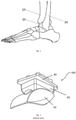
- Fig. 1 illustrates a simplified side view of the bones of the foot and ankle, including the distal tibia 10, the talus 20, and the distal fibula 30.
- the distal tibia 10 and the proximal talus 20 may be arthritic and need replacing with a partial or full joint replacement implant.
- FIG.2 illustrates an example of a full joint replacement implant 100 including a tibial component 40, a talar component 50, and a mobile bearing 60 (e.g., typically formed of ultra-high molecular weight polyethylene or other plastic) interposed between the tibial and talar components (e.g., typically formed of metal or the like).
- a mobile bearing 60 e.g., typically formed of ultra-high molecular weight polyethylene or other plastic
- talar component 150 which may be used as a partial joint replacement implant or as part of a total replacement ankle implant.
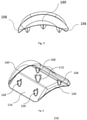
- Figs. 3-9 show one embodiment of such a talar component 150 for use in a total replacement ankle implant such as implant 100.
- Talar component 150 includes superior and inferior surfaces 152, 154, respectively, anterior and posterior edges 156, 158, respectively, and opposing medial and lateral side walls 160 extending at least partially between the anterior and posterior edges. From the top view, as shown in Fig. 4 , talar component 150 may taper outwardly from posterior edge 158 to anterior edge 156, such that the distance between side walls 160 is greater nearer to the anterior edge than the posterior edge.
- component 150 may be different depending on particular sizes of the implant, such as implants of an intended size for a particular anatomy of a particular patient, and the like.
- shape of talar component 150 is designed to cover the talar dome and the medial and lateral facets of the ankle as well as provide for a full range of motion in at least the anterior and posterior directions.
- the superior surface 152 of component 150 forms the articulation surface and has a shape complementary to the curvature of the other components of the full joint replacement implant, such as the bearing component, and in the illustrated embodiment, the superior surface is generally convex.
- a raised ridge 165 may optionally be positioned on the superior surface 152 and may project proximally from superior surface 152. Ridge 165 may extend in the anterior-posterior direction on the superior surface. Ridge 165 may be positioned anywhere on the superior surface as desired, such as substantially in the medial-lateral center of the superior surface and may further have a generally curved shape. If present, ridge 165 is designed to help constrain the motion of the bearing component in the medial-lateral direction. For example, during plantar flexion (e.g., flexion) or dorsiflexion (e.g., extension) of the ankle implant, ridge 165 would track within a complementary channel in the bearing component.
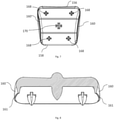
- inferior surface 154 is generally concave to conform to the talar dome of the natural ankle, and the adjacent side walls 160 defines an inferior volume.
- the talar component is designed to minimize the amount of bone removal during surgery.
- the inferior surface is designed to comport with the talar dome as closely as possible, since every anatomy is slightly different, the inferior surface 154 may not conform exactly to the talar dome, which may result in volume(s) of open space between the implant and the bone within the defined inferior volume.
- talar component 150 may also include at least one anchor 168, 170 extending distally from inferior surface 154 to a distal tip.
- anchors 168 are positioned spaced apart near anterior edge 156
- two anchors 168 are positioned spaced apart near posterior edge 158
- one anchor 170 is positioned substantially centrally on the inferior surface 154. This positioning of the anchors is substantially symmetrical in the lateral-medial direction, which may help to minimize rocking or tilting of the talar component relative to the talus 20.
- anchor 170 is larger in size than anchors 168; however, in other embodiments, the anchors may be any size relative to each other.
- anchor 170 may be the same size or smaller than anchors 168, and anchors 168 may all be different sizes relative to each other.
- Anchors 168, 170 aid in the fixation of talar component 150 to the bone, and may particularly assist in initial fixation.
- talar component 150 may include more or less anchors arranged in a variety of positions on the inferior surface 154, and may not include any anchors.
- the illustrated anchors 168, 170 are star-shaped, each anchor may have any shape desired.
- the illustrated anchors extend along axes that are generally parallel to one another and perpendicular to the component 150 body, each anchor may extend in any direction relative to the component body and/or one another as desired.
- each side wall 160 extends to and terminate at distal bone-cutting edges 161.
- each side wall 160 has a thickness, measured from outer surface 162 to inner surface 163 of the side walls, the thickness tapering to form bone-cutting edges 161.
- Bone-cutting edges 161 may have a sharpness capable of driving into bone, e.g., functioning as self-cutting edges.
- Edges 161 may be any type of edge that enables the edge to cut or drive into the bone, e.g. knife-edge, serrated, etc.
- Edges 161 and side walls 160 may drive into the bone to provide a flush fit with the talus with substantially little to no clearance or space between side walls 160 and the talus.
- the bone contacted by edges 161 may be the natural talus or could be the prepared cut surfaces of the talus, as discussed below.
- the fit is flush such that substantially all of side walls 160 (e.g., along length of side walls 160) of talar component 150 maintains contact with the talus after implantation which may form a seal to prevent synovial fluid from flowing under talar component 150 into any volume of open space which may be present between the bone and inferior surface 154 due to difference between the shape of the inferior surface 154 and the talus 20, as discussed above.
- the prevention of synovial fluid from seeping under the implant provides greater fixation of the implant to the bone and increases the longevity of the implant within the patient. Further, the fit between edges 161 and the bone 20 may supplement fixation by anchors 168, 170, or in some instances, could be sufficiently secure that anchors 168, 170 need not be present on the component 150.
- edges 161 and bone 20 may be particularly strong in instances where bone-cutting edges 161 could facilitate osteointegration between the talar component 150 and the bone.
- the anchorage of the talar component 150, and in particular the anchorage of edges 161, may enable the formation of bony tissue around the component to provide greater structural and functional connection between the component and the bone.
- one or both of side walls 160 may extend further distally than in the illustrated embodiment.
- one or both of the bone-cutting edges 161 may be positioned further distally, relative to the inferior surface 154 of the talar component 150 such that the edges 161 may extend deeper into the talus 20 which may provide for increased fixation and increased surface area for potential osteointegration, as discussed further below.
- talar component 150 may also include sharp bone-cutting edges on anterior and posterior edges 156, 158 (or, such cutting surface could be in place of edges 161, whereby medial/lateral walls 160 do not include cutting edges). In instances where all four sides 156, 158, 160 include cutting edges, such a talar component may have still further engagement ability with the talus to provide for improved sealing of any volume of open space between the inferior surface 154 and the bone 20, and further, could result in osteointegration around the perimeter of the component 150.
- Talar component 150 may be comprised of metal, such as titanium, ceramic, glass, polymer, or any other material known for use in the human body.
- the component 150 may also comprise one or more surface treatments, on any or all of inferior surface 154, edges 156, 158 and side walls 160, to encourage biological fixation, such as porous coating, plasma spray coating, e.g. titanium plasma spray coating, hydroxyapatite, or tricalcium phosphate.
- the present disclosure also includes a method of implanting talar component 150 on a prepared talus.
- the method generally includes cutting at least medial and lateral cuts on talus 20 to form a prepared talus, digging a bone-cutting edge 161 of a side wall 160 into one of the medial and lateral cuts and digging the second bone-cutting edge 161 of the second side wall into the other of the medial and lateral cuts.
- the medial and lateral cuts may be oversized to provide greater space for the bone-cutting edges to dig into the cut to form a seal between the side walls and the bone.
- the present disclosure may also include various systems and kits based on the components discussed above. While it is envisioned that these various components may be utilized, packaged, sold, or designed in any number of systems and kits, representative embodiments will be discussed in detail below.
- the present disclosure can include a kit which can be packaged in a single package as a system or in multiple packages that can be selected as needed by the operator to form a system.
- a kit may include at least one talar component 150, at least one tibial component, such as tibial component 40, and at least one mobile bearing, such as bearing 60.
- Any combination of components including the talar component may be included in a single package or in separate packaging which are later brought together as a kit. If multiple components of any of the specific components are present, such components may differ in size, material, configuration, and the like, such that the operator can select a particular component from a variety of available components depending on need based on surrounding anatomy, bone size, bone density, and the like.
- Any such kit may also include a surgical procedure which may include instructions or protocol for using the components and may include aspects of any of the above-discussed embodiments, though other variations are also envisioned within the scope of the present disclosure.
- the present disclosure includes a system for the repair of an ankle including at least one talar component, at least one mobile bearing, and at least one tibial component, and a surgical procedure.
- the surgical procedure may include instructions or protocol for using the components and may include aspects of any of the above-discussed embodiments, though other variations are also envisioned within the scope of the present disclosure.
Claims (13)
- Composant astragalien (150) d'une prothèse d'articulation de cheville destiné à s'engager avec l'os talus, comprenant une paroi latérale interne (160) et une paroi latérale externe (160), opposée à la paroi latérale interne,
caractérisé en ce que chaque paroi latérale se termine au niveau d'une arête de coupe osseuse distale (161) et chacune présente une certaine épaisseur, les épaisseurs s'effilant pour former les arêtes de coupe osseuse distales de telle sorte que les arêtes de coupe osseuse distales sont en mesure de pénétrer dans l'os talus. - Composant astragalien selon la revendication 1, où, lorsque le composant est engagé dans l'os talus, les parois latérales forment un joint entre l'os talus et le composant.
- Composant astragalien selon la revendication 2, comprenant en outre une surface inférieure (154), la surface inférieure, la paroi interne et la paroi externe définissant un volume inférieur, la surface inférieure étant positionnée de sorte à faire face à l'os talus.
- Composant astragalien selon la revendication 3, dans lequel le joint enferme une partie du volume inférieur au-dessus d'une surface de l'os talus.
- Composant astragalien selon l'une des revendications 3 et 4, dans lequel la surface inférieure est sensiblement concave.
- Composant astragalien selon l'une quelconque des revendications 3 à 5, comprenant en outre au moins un ancrage (168, 170) s'étendant distalement depuis la surface inférieure le long d'un axe longitudinal.
- Composant astragalien selon l'une quelconque des revendications précédentes, où le composant astragalien est symétrique par rapport à un axe s'étendant dans la direction antéro-postérieure du composant.
- Composant astragalien selon l'une quelconque des revendications 1 à 6, dans lequel l'une des parois latérales interne et externe s'étend davantage distalement que l'autre.
- Composant astragalien selon la revendication 1, comprenant en outre une surface inférieure, la surface inférieure et les parois latérales opposées définissant un volume inférieur et, lorsque le composant est engagé avec l'os talus, la surface inférieure et les parois latérales opposées forment un joint enfermant une partie du volume inférieur au-dessus d'une surface de l'os talus.
- Composant astragalien selon la revendication 9, dans lequel pour chaque paroi latérale, sensiblement toute la longueur de la paroi latérale reste en contact avec l'os talus après implantation.
- Composant astragalien selon l'une des revendications 9 et 10, dans lequel le joint entre le composant et l'os est conçu pour empêcher du fluide de s'écouler entre la surface inférieure et l'os.
- Composant astragalien selon la revendication 1, incluant en outre une arête intérieure (156) et une arête postérieure (158), et des arêtes de coupe osseuse tranchantes sur les arêtes antérieure et postérieure.
- Composant astragalien (150) d'une prothèse d'articulation de cheville destiné à s'engager avec l'os talus, comprenant une paroi latérale interne (160) et une paroi latérale externe (160), opposée à la paroi latérale interne,
caractérisé en ce que chaque paroi latérale se termine au niveau d'une arête de coupe osseuse distale (161), les arêtes de coupe osseuse distales étant des arêtes auto-coupantes, en lame de couteau, ou dentelées pour être en mesure de pénétrer dans l'os talus.
Applications Claiming Priority (2)
| Application Number | Priority Date | Filing Date | Title |
|---|---|---|---|
| US201762562007P | 2017-09-22 | 2017-09-22 | |
| EP18195986.7A EP3459501B8 (fr) | 2017-09-22 | 2018-09-21 | Implant de cheville astragalien |
Related Parent Applications (2)
| Application Number | Title | Priority Date | Filing Date |
|---|---|---|---|
| EP18195986.7A Division-Into EP3459501B8 (fr) | 2017-09-22 | 2018-09-21 | Implant de cheville astragalien |
| EP18195986.7A Division EP3459501B8 (fr) | 2017-09-22 | 2018-09-21 | Implant de cheville astragalien |
Publications (2)
| Publication Number | Publication Date |
|---|---|
| EP3769724A1 EP3769724A1 (fr) | 2021-01-27 |
| EP3769724B1 true EP3769724B1 (fr) | 2022-03-02 |
Family
ID=63678501
Family Applications (2)
| Application Number | Title | Priority Date | Filing Date |
|---|---|---|---|
| EP18195986.7A Active EP3459501B8 (fr) | 2017-09-22 | 2018-09-21 | Implant de cheville astragalien |
| EP20193876.8A Active EP3769724B1 (fr) | 2017-09-22 | 2018-09-21 | Implant de cheville astragalien |
Family Applications Before (1)
| Application Number | Title | Priority Date | Filing Date |
|---|---|---|---|
| EP18195986.7A Active EP3459501B8 (fr) | 2017-09-22 | 2018-09-21 | Implant de cheville astragalien |
Country Status (4)
| Country | Link |
|---|---|
| US (2) | US11013607B2 (fr) |
| EP (2) | EP3459501B8 (fr) |
| DK (1) | DK3769724T3 (fr) |
| ES (2) | ES2913991T3 (fr) |
Families Citing this family (4)
| Publication number | Priority date | Publication date | Assignee | Title |
|---|---|---|---|---|
| KR102018051B1 (ko) * | 2017-08-29 | 2019-09-04 | 주식회사 코렌텍 | 인공발목관절 경골요소 |
| AU2019302325B2 (en) | 2018-04-24 | 2024-05-02 | Paragon 28 Inc | Implants and methods of use and assembly |
| CN110013364A (zh) * | 2019-04-26 | 2019-07-16 | 中国人民解放军联勤保障部队第九二〇医院 | 一种高适形性距骨上端仿生耐固接距骨替换件 |
| CN110013360A (zh) * | 2019-04-26 | 2019-07-16 | 中国人民解放军联勤保障部队第九二〇医院 | 一种高适形性胫骨-距骨间仿生配合关节 |
Citations (1)
| Publication number | Priority date | Publication date | Assignee | Title |
|---|---|---|---|---|
| EP2124832B1 (fr) * | 2006-12-23 | 2012-08-08 | Corin Limited | Perfectionnements à et apparentés à une prothèse de cheville |
Family Cites Families (222)
| Publication number | Priority date | Publication date | Assignee | Title |
|---|---|---|---|---|
| US1505106A (en) | 1921-08-18 | 1924-08-19 | Alexander Bernhard Drager | Burner for the autogenous cutting of metals |
| DE2236141B2 (de) | 1972-07-22 | 1976-07-08 | Fa. Waldemar Link, 2000 Hamburg | Teilprothese fuer das sprunggelenk eines menschen |
| US3975778A (en) | 1975-07-14 | 1976-08-24 | Newton Iii St Elmo | Total ankle arthroplasty |
| US3987500A (en) | 1976-01-28 | 1976-10-26 | Schlein Allen P | Surgically implantable total ankle prosthesis |
| US4021864A (en) | 1976-04-14 | 1977-05-10 | The Regents Of The University Of California | Ankle prosthesis |
| US4069518A (en) | 1976-08-31 | 1978-01-24 | Groth Jr Harry E | Total ankle prosthesis |
| CH607579A5 (fr) | 1976-11-15 | 1978-09-15 | Sulzer Ag | |
| US4301552A (en) | 1977-05-20 | 1981-11-24 | Wright Manufacturing Company | Endoprosthetic joint device |
| GB1579773A (en) | 1977-07-18 | 1980-11-26 | Nat Res Dev | Endoprosthetic bone joint devices |
| US4166292A (en) | 1977-09-08 | 1979-09-04 | Carbomedics, Inc. | Stress reinforced artificial joint prostheses |
| US4229839A (en) | 1977-11-16 | 1980-10-28 | Lord Corporation | Joint prosthesis |
| US4289123A (en) | 1980-03-31 | 1981-09-15 | Dunn Harold K | Orthopedic appliance |
| US4501269A (en) | 1981-12-11 | 1985-02-26 | Washington State University Research Foundation, Inc. | Process for fusing bone joints |
| US4524766A (en) | 1982-01-07 | 1985-06-25 | Petersen Thomas D | Surgical knee alignment method and system |
| US4499900A (en) | 1982-11-26 | 1985-02-19 | Wright State University | System and method for treating paralyzed persons |
| US4569352A (en) | 1983-05-13 | 1986-02-11 | Wright State University | Feedback control system for walking |
| US4570927A (en) | 1983-12-15 | 1986-02-18 | Wright State University | Therapeutic device |
| US4990161A (en) | 1984-03-16 | 1991-02-05 | Kampner Stanley L | Implant with resorbable stem |
| US4586495A (en) | 1984-07-02 | 1986-05-06 | Wright State University | Therapy system for acute patient care |
| US4697808A (en) | 1985-05-16 | 1987-10-06 | Wright State University | Walking assistance system |
| US4655778A (en) | 1985-08-12 | 1987-04-07 | Harrington Arthritis Research Center | Joint prosthesis |
| US4711242A (en) | 1986-02-18 | 1987-12-08 | Wright State University | Control system for knee joint |
| US4978357A (en) * | 1987-06-12 | 1990-12-18 | Mecron Medizinische Produkte Gmbh | Endoprosthesis |
| US7491205B1 (en) | 1988-06-13 | 2009-02-17 | Warsaw Orthopedic, Inc. | Instrumentation for the surgical correction of human thoracic and lumbar spinal disease from the lateral aspect of the spine |
| SE466937B (sv) | 1989-04-25 | 1992-05-04 | Branemark Per Ingvar | Foerankringsanordning foer till benvaevnad applicerbara proteser, spec ledmekanismer |
| US5122144A (en) | 1989-09-26 | 1992-06-16 | Kirschner Medical Corporation | Method and instrumentation for unicompartmental total knee arthroplasty |
| US5074285A (en) | 1989-11-20 | 1991-12-24 | Wright Linear Pump, Inc. | Thermal applicator method |
| US5063937A (en) | 1990-09-12 | 1991-11-12 | Wright State University | Multiple frequency bio-impedance measurement system |
| US5020519A (en) | 1990-12-07 | 1991-06-04 | Zimmer, Inc. | Sagittal approximator |
| US5219364A (en) | 1991-09-12 | 1993-06-15 | Wright & Filippis, Inc. | Continuous one-piece prosthesis |
| US5344423A (en) | 1992-02-06 | 1994-09-06 | Zimmer, Inc. | Apparatus and method for milling bone |
| US5326365A (en) | 1992-04-10 | 1994-07-05 | Alvine Franklin G | Ankle implant |
| US5431653A (en) | 1993-07-06 | 1995-07-11 | Callaway; George H. | Knee joint flexion-gap distraction device |
| DE4328690B4 (de) | 1993-08-26 | 2006-08-17 | SDGI Holdings, Inc., Wilmington | Zwischenwirbelimplantat zur Wirbelkörperverblockung und Implantationsinstrument zum Positionieren des Zwischenwirbelimplantats |
| US6517583B1 (en) | 2000-01-30 | 2003-02-11 | Diamicron, Inc. | Prosthetic hip joint having a polycrystalline diamond compact articulation surface and a counter bearing surface |
| US6695848B2 (en) | 1994-09-02 | 2004-02-24 | Hudson Surgical Design, Inc. | Methods for femoral and tibial resection |
| US5514139A (en) | 1994-09-02 | 1996-05-07 | Hudson Surgical Design, Inc. | Method and apparatus for femoral resection |
| US5810827A (en) | 1994-09-02 | 1998-09-22 | Hudson Surgical Design, Inc. | Method and apparatus for bony material removal |
| US5885299A (en) | 1994-09-15 | 1999-03-23 | Surgical Dynamics, Inc. | Apparatus and method for implant insertion |
| US5630820A (en) | 1994-12-05 | 1997-05-20 | Sulzer Orthopedics Inc. | Surgical bicompartmental tensiometer for revision knee surgery |
| US5993487A (en) | 1994-12-29 | 1999-11-30 | Wright & Filippis | Integrated keel-pylon prosthesis |
| US5766259A (en) | 1995-03-14 | 1998-06-16 | Sammarco; Giacomo J. | Total ankle prosthesis and method |
| US5571184A (en) | 1995-06-07 | 1996-11-05 | Wright Medical Technology, Inc. | Graft fixation device and method of using |
| US5916216A (en) | 1995-06-07 | 1999-06-29 | Wright Medical Technology, Inc. | Graft fixation devices |
| US5649929A (en) | 1995-07-10 | 1997-07-22 | Callaway; George Hadley | Knee joint flexion-gap distraction device |
| US5662656A (en) | 1995-12-08 | 1997-09-02 | Wright Medical Technology, Inc. | Instrumentation and method for distal femoral sizing, and anterior and distal femoral resections |
| US5682886A (en) | 1995-12-26 | 1997-11-04 | Musculographics Inc | Computer-assisted surgical system |
| FR2747302B1 (fr) | 1996-04-11 | 1998-09-11 | Tornier Sa | Prothese de cheville |
| US6159214A (en) | 1996-07-31 | 2000-12-12 | Michelson; Gary K. | Milling instrumentation and method for preparing a space between adjacent vertebral bodies |
| US8556983B2 (en) | 2001-05-25 | 2013-10-15 | Conformis, Inc. | Patient-adapted and improved orthopedic implants, designs and related tools |
| US7618451B2 (en) | 2001-05-25 | 2009-11-17 | Conformis, Inc. | Patient selectable joint arthroplasty devices and surgical tools facilitating increased accuracy, speed and simplicity in performing total and partial joint arthroplasty |
| US7468075B2 (en) | 2001-05-25 | 2008-12-23 | Conformis, Inc. | Methods and compositions for articular repair |
| US6090114A (en) | 1997-02-10 | 2000-07-18 | Stryker Howmedica Osteonics Corp. | Tibial plateau resection guide |
| FR2760353B1 (fr) | 1997-03-10 | 1999-07-02 | Tornier Sa | Prothese de cheville |
| WO1999003430A1 (fr) | 1997-07-16 | 1999-01-28 | Knapp John G | Prothese d'articulation |
| US7419491B2 (en) | 1997-09-18 | 2008-09-02 | Medidea, Llc | Bone-conserving orthopedic instrumentation and appliances |
| US6053945A (en) | 1997-09-25 | 2000-04-25 | Johnson & Johnson Professional, Inc. | Joint prosthesis having controlled rotation |
| FR2770393B1 (fr) | 1997-10-31 | 1999-12-31 | Protek Sa | Dispositif de coupe femorale pour la pose d'une prothese totale de genou de reprise |
| US6007537A (en) | 1998-06-15 | 1999-12-28 | Sulzer Orthopedics Inc. | Nested cutting block |
| ES2224406T3 (es) | 1998-06-29 | 2005-03-01 | Plus Endoprothetik Ag | Dispositivo para insertar una protesis de rodilla. |
| EP1117335B1 (fr) | 1998-10-02 | 2009-03-25 | Synthes GmbH | Ecarteur de l'espace intervertebral |
| US6174314B1 (en) | 1998-12-15 | 2001-01-16 | David D. Waddell | In situ pattellar resection guide |
| IT1310371B1 (it) | 1999-05-13 | 2002-02-13 | Ist Ortopedici Rizzoli | Dispositivo di protesi per articolazione umana, in particolare perarticolazione della tibotarsica e relativo metodo di impianto. |
| US20050033442A1 (en) | 1999-09-08 | 2005-02-10 | John Fisher | Combination of material for joint prothesis |
| NZ543601A (en) | 1999-09-14 | 2008-08-29 | Spine Solutions Inc | Insertion instrument for an intervertebral implant |
| US6520967B1 (en) | 1999-10-20 | 2003-02-18 | Cauthen Research Group, Inc. | Spinal implant insertion instrument for spinal interbody prostheses |
| US8496712B2 (en) | 1999-10-22 | 2013-07-30 | Inbone Technologies, Inc. | Systems and methods for installing ankle replacement prostheses |
| AU2118601A (en) | 1999-10-22 | 2001-05-08 | Mark A. Reiley | Ankle replacement system |
| US6673116B2 (en) | 1999-10-22 | 2004-01-06 | Mark A. Reiley | Intramedullary guidance systems and methods for installing ankle replacement prostheses |
| GB9925956D0 (en) | 1999-11-02 | 1999-12-29 | Novarticulate Bv | Joint prostheses |
| FR2800601B1 (fr) | 1999-11-05 | 2002-01-04 | Europ Foot Platform | Prothese de cheville |
| US6245109B1 (en) | 1999-11-18 | 2001-06-12 | Intellijoint Systems, Ltd. | Artificial joint system and method utilizing same for monitoring wear and displacement of artificial joint members |
| US7635390B1 (en) | 2000-01-14 | 2009-12-22 | Marctec, Llc | Joint replacement component having a modular articulating surface |
| US6911047B2 (en) | 2000-03-17 | 2005-06-28 | Depuy Orthopaedics, Inc. | Apparatus and method for securing a cementless glenoid component to a glenoid surface of a scapula |
| US6478800B1 (en) | 2000-05-08 | 2002-11-12 | Depuy Acromed, Inc. | Medical installation tool |
| FR2808994B1 (fr) | 2000-05-22 | 2003-03-21 | Transysteme Sarl | Prothese d'articulation |
| US7204851B2 (en) | 2000-08-30 | 2007-04-17 | Sdgi Holdings, Inc. | Method and apparatus for delivering an intervertebral disc implant |
| US6482236B2 (en) | 2000-10-12 | 2002-11-19 | Matthew J. Habecker | Prosthetic ankle joint mechanism |
| US6599291B1 (en) | 2000-10-20 | 2003-07-29 | Sdgi Holdings, Inc. | Methods and instruments for interbody surgical techniques |
| EP1222903B1 (fr) | 2001-01-12 | 2005-01-19 | Link Spine Group, Inc. | Instrument chirurgical pour implanter une prothèse intervertébrale |
| US6551316B1 (en) | 2001-03-02 | 2003-04-22 | Beere Precision Medical Instruments, Inc. | Selective compression and distraction instrument |
| US20020143343A1 (en) | 2001-03-27 | 2002-10-03 | Surgical Dynamics, Inc. | Method and apparatus for spinal implant insertion |
| US6686437B2 (en) | 2001-10-23 | 2004-02-03 | M.M.A. Tech Ltd. | Medical implants made of wear-resistant, high-performance polyimides, process of making same and medical use of same |
| US7963971B2 (en) | 2001-10-29 | 2011-06-21 | Depuy Spine, Inc. | Instrumentation for insertion of an inter-vertebral prosthesis |
| AU2002348204A1 (en) | 2001-11-28 | 2003-06-10 | Wright Medical Technology, Inc. | Instrumentation for minimally invasive unicompartmental knee replacement |
| US7141053B2 (en) | 2001-11-28 | 2006-11-28 | Wright Medical Technology, Inc. | Methods of minimally invasive unicompartmental knee replacement |
| US6699289B2 (en) | 2001-12-31 | 2004-03-02 | Depuy Orthopaedics, Inc. | Augmented glenoid component having an interrupted surface and associated method for securing the augmented glenoid component to a glenoid surface of a scapula |
| JP4202268B2 (ja) | 2002-03-08 | 2008-12-24 | ヴァルデマール・リンク・ゲゼルシャフト・ミット・ベシュレンクテル・ハフツング・ウント・コムパニー・コマンディットゲゼルシャフト | 足首関節エンドプロテーゼ |
| US6863691B2 (en) | 2002-04-29 | 2005-03-08 | Timothy J. Short | Ankle implant |
| WO2003092507A2 (fr) | 2002-05-06 | 2003-11-13 | Sdgi Holdings, Inc. | Instrumentation et procedes de preparation d'un espace intervertebral |
| US7048741B2 (en) | 2002-05-10 | 2006-05-23 | Swanson Todd V | Method and apparatus for minimally invasive knee arthroplasty |
| US8388684B2 (en) | 2002-05-23 | 2013-03-05 | Pioneer Signal Technology, Inc. | Artificial disc device |
| US20030236522A1 (en) | 2002-06-21 | 2003-12-25 | Jack Long | Prosthesis cavity cutting guide, cutting tool and method |
| US7025790B2 (en) | 2002-06-27 | 2006-04-11 | Concepts In Medicine Iii, L.L.C. | Ankle joint prosthesis and its method of implantation |
| US7931674B2 (en) | 2005-03-21 | 2011-04-26 | Kyphon Sarl | Interspinous process implant having deployable wing and method of implantation |
| US7094241B2 (en) | 2002-11-27 | 2006-08-22 | Zimmer Technology, Inc. | Method and apparatus for achieving correct limb alignment in unicondylar knee arthroplasty |
| US6866683B2 (en) | 2002-12-13 | 2005-03-15 | Medicine Lodge, Inc. | Modular implant for joint reconstruction and method of use |
| US6887276B2 (en) | 2002-12-13 | 2005-05-03 | Medicine Lodge, Inc | Modular implant for joint reconstruction and method of use |
| US20040122519A1 (en) | 2002-12-20 | 2004-06-24 | Wiley Roy C. | Prosthetic glenoid |
| US6939380B2 (en) | 2002-12-23 | 2005-09-06 | Depuy Products, Inc. | Mobile talar component for total ankle replacement implant |
| US7011687B2 (en) | 2003-01-06 | 2006-03-14 | Depuy Products, Inc. | Ankle prosthesis with a front loading bearing and associated method |
| US20040167631A1 (en) | 2003-02-21 | 2004-08-26 | Kenny Luchesi | Fixation surface for ankle prosthesis |
| US20040186585A1 (en) | 2003-03-21 | 2004-09-23 | Lawrence Feiwell | Sphere-on-sphere ankle prosthesis |
| EP1468652A1 (fr) | 2003-04-16 | 2004-10-20 | Paul M. Tsou | Dispositif pour la chirurgie rachidienne |
| US20070027547A1 (en) | 2003-06-27 | 2007-02-01 | Advanced Bio Surfaces, Inc. | System and method for ankle arthroplasty |
| US20050015095A1 (en) | 2003-07-15 | 2005-01-20 | Cervitech, Inc. | Insertion instrument for cervical prostheses |
| US7806932B2 (en) | 2003-08-01 | 2010-10-05 | Zimmer Spine, Inc. | Spinal implant |
| ATE357195T1 (de) | 2003-08-27 | 2007-04-15 | Link Waldemar Gmbh Co | Sprunggelenk-endoprothese |
| US20050049710A1 (en) | 2003-08-28 | 2005-03-03 | O'driscoll Shawn W. | Prosthesis for partial replacement of an articulating surface on bone |
| US7534270B2 (en) | 2003-09-03 | 2009-05-19 | Integra Lifesciences Corporation | Modular total ankle prosthesis apparatuses and methods |
| EP1677709B1 (fr) | 2003-10-14 | 2012-02-01 | University Of Iowa Research Foundation | Prothese de cheville |
| US9445916B2 (en) | 2003-10-22 | 2016-09-20 | Pioneer Surgical Technology, Inc. | Joint arthroplasty devices having articulating members |
| US7625379B2 (en) | 2004-01-26 | 2009-12-01 | Warsaw Orthopedic, Inc. | Methods and instrumentation for inserting intervertebral grafts and devices |
| US7485147B2 (en) | 2004-02-13 | 2009-02-03 | Pappas Michael J | Ankle prosthesis including tibial component having peripheral wall for preventing the formation of bone cysts |
| US7323012B1 (en) | 2004-03-17 | 2008-01-29 | Biomet Manufacturing Corp. | Ankle implant |
| US7465303B2 (en) | 2004-04-22 | 2008-12-16 | Wright Medical Technology, Inc. | External fixation assembly |
| US7776051B2 (en) | 2004-05-03 | 2010-08-17 | Theken Spine, Llc | System and method for displacement of bony structures |
| US20050288792A1 (en) | 2004-06-23 | 2005-12-29 | Landes Mark D | Modular ankle prosthesis and associated method |
| US7470273B2 (en) | 2004-06-25 | 2008-12-30 | Ebi, Llc | Tool for intervertebral implant manipulation |
| US9237958B2 (en) | 2004-06-30 | 2016-01-19 | Synergy Disc Replacement Inc. | Joint prostheses |
| US20060041311A1 (en) | 2004-08-18 | 2006-02-23 | Mcleer Thomas J | Devices and methods for treating facet joints |
| EP1809209A2 (fr) | 2004-08-19 | 2007-07-25 | Kinetikos Medical Incorporated | Appareils, systemes et procedes modulaires de prothese totale de la cheville, et systemes et procedes pour la resection osseuse et l'implantation prothetique |
| US7361194B2 (en) | 2004-10-14 | 2008-04-22 | Wright Medical Technology, Inc. | Metallic bearings for joint replacement |
| AT502926B1 (de) | 2004-11-08 | 2011-04-15 | Alphamed Medizintechnik Fischer Gmbh | Sprunggelenksprothesenelemente |
| US20060100634A1 (en) | 2004-11-09 | 2006-05-11 | Sdgi Holdings, Inc. | Technique and instrumentation for measuring and preparing a vertebral body for device implantation using datum block |
| EP1814474B1 (fr) | 2004-11-24 | 2011-09-14 | Samy Abdou | Dispositifs de placement d'un dispositif orthopedique intervertebral |
| EP1890649A4 (fr) | 2004-11-30 | 2011-03-30 | Mansmann Kevin A | Systemes d'ancrage et interfaces pour des implants chirurgicaux flexibles destines a remplacer le cartilage |
| US20070038303A1 (en) | 2006-08-15 | 2007-02-15 | Ebi, L.P. | Foot/ankle implant and associated method |
| US20060136058A1 (en) | 2004-12-17 | 2006-06-22 | William Pietrzak | Patient specific anatomically correct implants to repair or replace hard or soft tissue |
| US7632279B2 (en) | 2004-12-27 | 2009-12-15 | Howmedica Osteonics Corp. | Patella resection clamp |
| US8734453B2 (en) | 2005-02-21 | 2014-05-27 | Wright Medical Technology, Inc. | Instruments for minimally invasive surgery total knee arthroplasty |
| US20060195116A1 (en) | 2005-02-25 | 2006-08-31 | Fox Michael D | D-Tail patellar bone tunneling system |
| AU2006223238B2 (en) | 2005-03-14 | 2011-09-29 | Inbone Technologies, Inc. | Ankle replacement system |
| US20060247788A1 (en) | 2005-03-31 | 2006-11-02 | The Regents Of The University Of California | Total ankle arthroplasty |
| GB0519829D0 (en) | 2005-09-30 | 2005-11-09 | Depuy Int Ltd | Distractor instrument |
| GB0519832D0 (en) | 2005-09-30 | 2005-11-09 | Depuy Int Ltd | Instrument assembly for use in knee joint replacement surgery |
| WO2007047556A2 (fr) | 2005-10-14 | 2007-04-26 | Microchips, Inc. | Capteur indicateur d'usure passif pour prothese implantable |
| BRPI0619626A2 (pt) | 2005-12-12 | 2011-10-04 | Link Waldemar Gmbh Co | endoprótese com elemento intermediário |
| US20070135924A1 (en) | 2005-12-14 | 2007-06-14 | Verhoogen Alex R | Joint replacement prosthesis, joint replacement mounting stud and method |
| WO2007084846A2 (fr) | 2006-01-20 | 2007-07-26 | Hasselman Carl T | Procede de preparation au remplacement d’une articulation tibio-tarsienne, prothese d'articulation et appareil d’alignement de coupe a utiliser lors d'une procedure d'arthroplastie |
| FR2896404B1 (fr) | 2006-01-24 | 2008-02-29 | Tornier Sas | Ensemble d'instrumentation chirurgicale pour poser une prothese de cheville |
| US7766918B2 (en) | 2006-01-31 | 2010-08-03 | Warsaw Orthopedic, Inc. | Spinal disc replacement surgical instrument and methods for use in spinal disc replacement |
| US7828805B2 (en) | 2006-02-02 | 2010-11-09 | Zimmer Technology, Inc. | Hip stem centralizer datum guide, and method |
| US9044323B2 (en) | 2006-02-06 | 2015-06-02 | Kyocera Medical Corporation | High wear-resistant bearing material and artificial joint replacement using the same |
| US7780672B2 (en) | 2006-02-27 | 2010-08-24 | Biomet Manufacturing Corp. | Femoral adjustment device and associated method |
| JP2009531078A (ja) | 2006-03-02 | 2009-09-03 | タラス メディカル, インコーポレイテッド | 人工骨 |
| US7842092B2 (en) | 2006-03-14 | 2010-11-30 | Mako Surgical Corp. | Prosthetic device and system and method for implanting prosthetic device |
| US8241292B2 (en) | 2006-06-30 | 2012-08-14 | Howmedica Osteonics Corp. | High tibial osteotomy system |
| US20080051909A1 (en) | 2006-08-22 | 2008-02-28 | The Hospital For Special Surgery | Wrist implants |
| US7896884B2 (en) | 2006-12-01 | 2011-03-01 | Aesculap, Inc. | Interbody distractor |
| US8979931B2 (en) | 2006-12-08 | 2015-03-17 | DePuy Synthes Products, LLC | Nucleus replacement device and method |
| CA2672555A1 (fr) | 2006-12-15 | 2008-06-26 | Synthes Usa, Llc | Guide d'osteotomie et procede de decoupe du tibia distal median utilisant celui-ci |
| US20080167655A1 (en) | 2007-01-05 | 2008-07-10 | Jeffrey Chun Wang | Interspinous implant, tools and methods of implanting |
| US8277448B2 (en) | 2007-03-07 | 2012-10-02 | Wright Medical Technology, Inc. | External fixation |
| US20080249574A1 (en) | 2007-03-20 | 2008-10-09 | Mccombs Mary | Bone Screw System |
| GB2447702A (en) | 2007-03-23 | 2008-09-24 | Univ Leeds | Surgical bone cutting template |
| US8172848B2 (en) | 2007-04-27 | 2012-05-08 | Spinemedica, Llc | Surgical instruments for spinal disc implants and related methods |
| WO2008151644A1 (fr) | 2007-06-12 | 2008-12-18 | Link America, Inc. | Endoprothèse à structure bombée |
| WO2008157412A2 (fr) | 2007-06-13 | 2008-12-24 | Conformis, Inc. | Guide d'incision chirurgical |
| US20080311315A1 (en) | 2007-06-13 | 2008-12-18 | Peter Marlow | Animated artificial flower |
| US20090018665A1 (en) | 2007-07-09 | 2009-01-15 | Exploramed Nc4, Inc. | Surgical implantation method and devices for an extra-articular mechanical energy absorbing apparatus |
| WO2009015009A1 (fr) | 2007-07-20 | 2009-01-29 | Talus Medical, Inc. | Procédés et dispositifs pour déployer des implants biologiques |
| US8486081B2 (en) | 2007-07-23 | 2013-07-16 | DePuy Synthes Products, LLC | Implant insertion device and method |
| US7628818B2 (en) | 2007-09-28 | 2009-12-08 | Depuy Products, Inc. | Fixed-bearing knee prosthesis having interchangeable components |
| US8128703B2 (en) | 2007-09-28 | 2012-03-06 | Depuy Products, Inc. | Fixed-bearing knee prosthesis having interchangeable components |
| US8470047B2 (en) | 2007-09-25 | 2013-06-25 | Depuy (Ireland) | Fixed-bearing knee prosthesis |
| US8632600B2 (en) | 2007-09-25 | 2014-01-21 | Depuy (Ireland) | Prosthesis with modular extensions |
| US8715359B2 (en) | 2009-10-30 | 2014-05-06 | Depuy (Ireland) | Prosthesis for cemented fixation and method for making the prosthesis |
| US9204967B2 (en) | 2007-09-28 | 2015-12-08 | Depuy (Ireland) | Fixed-bearing knee prosthesis having interchangeable components |
| US20110009964A1 (en) | 2008-02-28 | 2011-01-13 | Biopoly, Llc | Partial joint resurfacing implant, instrumentation and method |
| US9216085B2 (en) | 2008-02-28 | 2015-12-22 | Biopoly, Llc | Partial joint resurfacing implant, instrumentation, and method |
| US8864770B2 (en) | 2008-03-12 | 2014-10-21 | Spinal Elements, Inc. | Offset opposing arm spinal implant distractor/inserter |
| US8221425B2 (en) | 2008-04-30 | 2012-07-17 | Warsaw Orthopedic, Inc. | Percutaneous discectomy and endplate preparation tool |
| US9168065B2 (en) | 2008-04-30 | 2015-10-27 | Moximed, Inc. | Ball and socket assembly |
| US8871142B2 (en) | 2008-05-22 | 2014-10-28 | DePuy Synthes Products, LLC | Implants with roughened surfaces |
| EP2326263B1 (fr) | 2008-05-30 | 2019-02-27 | Wright Medical Technology, Inc. | Ensemble de guidage de foret |
| US8267966B2 (en) | 2008-06-06 | 2012-09-18 | Providence Medical Technology, Inc. | Facet joint implants and delivery tools |
| EP2337510B1 (fr) | 2008-06-25 | 2018-10-31 | Stryker European Holdings I, LLC | Instrumentation chirurgicale pour implanter une prothèse |
| US20100057216A1 (en) | 2008-07-23 | 2010-03-04 | Jamy Gannoe | System and method for joint resurfacing with dynamic fixation |
| US8545501B2 (en) | 2008-10-22 | 2013-10-01 | Wright Medical Technology, Inc. | Instruments for preparing bone implants |
| EP2358309B1 (fr) | 2008-12-18 | 2015-09-09 | 4-web Spine, Inc. | Implant à armatures intercalaires |
| US9017334B2 (en) | 2009-02-24 | 2015-04-28 | Microport Orthopedics Holdings Inc. | Patient specific surgical guide locator and mount |
| US8808297B2 (en) | 2009-02-24 | 2014-08-19 | Microport Orthopedics Holdings Inc. | Orthopedic surgical guide |
| US8808303B2 (en) | 2009-02-24 | 2014-08-19 | Microport Orthopedics Holdings Inc. | Orthopedic surgical guide |
| US8282590B2 (en) | 2009-03-27 | 2012-10-09 | Wright State University | Toe brace designs |
| US9101476B2 (en) | 2009-05-21 | 2015-08-11 | Depuy (Ireland) | Prosthesis with surfaces having different textures and method of making the prosthesis |
| US8268007B2 (en) | 2009-06-26 | 2012-09-18 | The Cleveland Clinic Foundation | Multi-piece prosthetic joint component |
| US20110035019A1 (en) | 2009-07-09 | 2011-02-10 | Wright State University | Total ankle replacement system |
| WO2011008739A2 (fr) | 2009-07-14 | 2011-01-20 | Medicinelodge, Inc. Dba Imds Co-Innovation | Arthrodésie et arthroplastie des articulations |
| US8403935B2 (en) | 2009-11-10 | 2013-03-26 | Wright Medical Technology, Inc. | Adjustable revision guide |
| EP3158976A1 (fr) | 2009-11-16 | 2017-04-26 | New York Society for the Ruptured and Crippled Maintaining the Hospital for Special Surgery | Articulations condyliennes prothétique avec surfaces d'appui articulées ayant un point de contact à translation pendant la rotation |
| US9763720B2 (en) | 2009-11-17 | 2017-09-19 | Wright Medical Technology, Inc. | Method and device for insertion of orthopedic fixation pin with blind hole |
| WO2011082343A1 (fr) | 2009-12-31 | 2011-07-07 | Tristar Medical Solutions, Llc | Procédé et dispositif pour fusionner les os d'une articulation |
| US9492281B2 (en) | 2010-02-19 | 2016-11-15 | European Foot Platform Sc | Ankle prosthesis with simplified adjustment |
| US9180012B2 (en) | 2010-05-18 | 2015-11-10 | Smith & Nephew, Inc. | Application of diffusion hardened material |
| US8591596B2 (en) | 2010-05-28 | 2013-11-26 | DePuy Synthes Products, LLC | Semi-constrained ankle prosthesis having a rotating bearing insert |
| US20110313532A1 (en) | 2010-06-18 | 2011-12-22 | Jessee Hunt | Bone implant interface system and method |
| US20120010718A1 (en) | 2010-07-08 | 2012-01-12 | Still Gregory P | Partial ankle joint replacement implant |
| US9468532B2 (en) | 2011-11-01 | 2016-10-18 | Adam D. Perler | Semi constrained polyaxial endoprosthetic ankle joint replacement implant |
| US8668743B2 (en) * | 2010-11-02 | 2014-03-11 | Adam D. Perler | Prosthetic device with multi-axis dual bearing assembly and methods for resection |
| US8597361B2 (en) | 2010-11-11 | 2013-12-03 | Bioshift, Llc | Joint implant fixation system |
| US8496713B2 (en) | 2010-12-10 | 2013-07-30 | Globus Medical, Inc. | Spine stabilization device and methods |
| US8998991B2 (en) | 2011-02-23 | 2015-04-07 | Globus Medical, Inc. | Six degree spine stabilization devices and methods |
| US20120245701A1 (en) | 2011-03-24 | 2012-09-27 | Rudolf Zak | Hemi Ankle Implant |
| US20120271430A1 (en) | 2011-04-22 | 2012-10-25 | Medicinelodge, Inc. Dba Imds Co-Innovation | Ankle arthroplasty |
| US20130030529A1 (en) | 2011-07-29 | 2013-01-31 | Jessee Hunt | Implant interface system and method |
| US8979937B2 (en) | 2011-09-27 | 2015-03-17 | Linares Medical Devices, Llc | Implantable ankle joint assembly with spherical inter-support |
| EP2773293B1 (fr) | 2011-11-03 | 2017-08-30 | 4-web, Inc. | Implant pour préservation de la longueur au cours d'une réparation osseuse |
| FR2986415A1 (fr) | 2012-02-06 | 2013-08-09 | Tornier Sa | Ensemble d'instrumentation chirurgicale pour poser une prothese de cheville |
| US9125753B2 (en) | 2012-02-17 | 2015-09-08 | Ervin Caballes | Elastomeric artificial joints and intervertebral prosthesis systems |
| EP2649966A1 (fr) | 2012-04-12 | 2013-10-16 | Arthrex, Inc. | Implant de surface de talus |
| US9144500B2 (en) | 2012-09-20 | 2015-09-29 | Michael G. Harding, Jr. | Ankle replacement devices and methods of making and using the same |
| US20140128985A1 (en) | 2012-11-07 | 2014-05-08 | Roy W. Sanders | Joint Arthroplasty Systems, Methods, and Components |
| EP2920271A4 (fr) | 2012-11-19 | 2016-05-25 | 3M Innovative Properties Co | Procédé de mise en contact de formations portant des hydrocarbures avec des polymères ioniques fluorés |
| US9918724B2 (en) | 2012-12-27 | 2018-03-20 | Wright Medical Technology, Inc. | Ankle replacement system and method |
| US10080573B2 (en) | 2012-12-27 | 2018-09-25 | Wright Medical Technology, Inc. | Ankle replacement system and method |
| US9480571B2 (en) | 2012-12-27 | 2016-11-01 | Wright Medical Technology, Inc. | Ankle replacement system and method |
| US9974588B2 (en) | 2012-12-27 | 2018-05-22 | Wright Medical Technology, Inc. | Ankle replacement system and method |
| US9237953B2 (en) | 2013-03-15 | 2016-01-19 | Depuy (Ireland) | Mechanical assembly of pegs to prosthesis |
| US9610168B2 (en) | 2014-05-12 | 2017-04-04 | Integra Lifesciences Corporation | Total ankle replacement prosthesis |
| CA2889245C (fr) * | 2014-11-07 | 2018-05-01 | Kian-Ming Wong | Tige de fixation de la tete d'astragale |
| US10426494B2 (en) * | 2017-08-24 | 2019-10-01 | Limacorporate S.P.A. | Ankle arthroplasty systems and methods |
-
2018
- 2018-09-21 EP EP18195986.7A patent/EP3459501B8/fr active Active
- 2018-09-21 EP EP20193876.8A patent/EP3769724B1/fr active Active
- 2018-09-21 DK DK20193876.8T patent/DK3769724T3/da active
- 2018-09-21 ES ES20193876T patent/ES2913991T3/es active Active
- 2018-09-21 ES ES18195986T patent/ES2832739T3/es active Active
- 2018-09-21 US US16/137,834 patent/US11013607B2/en active Active
-
2021
- 2021-05-24 US US17/328,306 patent/US20210338448A1/en active Pending
Patent Citations (1)
| Publication number | Priority date | Publication date | Assignee | Title |
|---|---|---|---|---|
| EP2124832B1 (fr) * | 2006-12-23 | 2012-08-08 | Corin Limited | Perfectionnements à et apparentés à une prothèse de cheville |
Also Published As
| Publication number | Publication date |
|---|---|
| ES2913991T3 (es) | 2022-06-07 |
| US20210338448A1 (en) | 2021-11-04 |
| ES2832739T3 (es) | 2021-06-11 |
| EP3459501B8 (fr) | 2021-01-20 |
| US11013607B2 (en) | 2021-05-25 |
| EP3459501A1 (fr) | 2019-03-27 |
| DK3769724T3 (da) | 2022-05-30 |
| EP3459501B1 (fr) | 2020-09-02 |
| US20190091032A1 (en) | 2019-03-28 |
| EP3769724A1 (fr) | 2021-01-27 |
Similar Documents
| Publication | Publication Date | Title |
|---|---|---|
| CA2906631C (fr) | Prothese unicompartimentale de genou | |
| US20210338448A1 (en) | Talar Ankle Implant | |
| US8118868B2 (en) | Method and apparatus for attaching soft tissue to an implant | |
| US6797006B2 (en) | Porous unicondylar knee | |
| EP3400911B1 (fr) | Plateau tibial ayant des fonctions de fixation | |
| US20090138096A1 (en) | Foot/ankle implant and associated method | |
| JP2008253771A (ja) | 可動式支持アセンブリ | |
| KR20070094730A (ko) | 발목 관절용 관내인공보철물 요소 | |
| US8690955B2 (en) | Device for unicompartmental knee arthroplasty | |
| EP2436341B1 (fr) | Composant fémoral d'une prothèse de genou | |
| AU2008255048B2 (en) | Surgically implantable knee prosthesis with captured keel | |
| US9474620B2 (en) | Talonavicular joint prosthesis and its method of implantation |
Legal Events
| Date | Code | Title | Description |
|---|---|---|---|
| PUAI | Public reference made under article 153(3) epc to a published international application that has entered the european phase |
Free format text: ORIGINAL CODE: 0009012 |
|
| STAA | Information on the status of an ep patent application or granted ep patent |
Free format text: STATUS: REQUEST FOR EXAMINATION WAS MADE |
|
| 17P | Request for examination filed |
Effective date: 20200901 |
|
| AC | Divisional application: reference to earlier application |
Ref document number: 3459501 Country of ref document: EP Kind code of ref document: P |
|
| AK | Designated contracting states |
Kind code of ref document: A1 Designated state(s): AL AT BE BG CH CY CZ DE DK EE ES FI FR GB GR HR HU IE IS IT LI LT LU LV MC MK MT NL NO PL PT RO RS SE SI SK SM TR |
|
| GRAP | Despatch of communication of intention to grant a patent |
Free format text: ORIGINAL CODE: EPIDOSNIGR1 |
|
| STAA | Information on the status of an ep patent application or granted ep patent |
Free format text: STATUS: GRANT OF PATENT IS INTENDED |
|
| INTG | Intention to grant announced |
Effective date: 20210831 |
|
| RIN1 | Information on inventor provided before grant (corrected) |
Inventor name: LORING, THOMAS Inventor name: PAK, CHULHO |
|
| GRAS | Grant fee paid |
Free format text: ORIGINAL CODE: EPIDOSNIGR3 |
|
| GRAA | (expected) grant |
Free format text: ORIGINAL CODE: 0009210 |
|
| STAA | Information on the status of an ep patent application or granted ep patent |
Free format text: STATUS: THE PATENT HAS BEEN GRANTED |
|
| AC | Divisional application: reference to earlier application |
Ref document number: 3459501 Country of ref document: EP Kind code of ref document: P |
|
| AK | Designated contracting states |
Kind code of ref document: B1 Designated state(s): AL AT BE BG CH CY CZ DE DK EE ES FI FR GB GR HR HU IE IS IT LI LT LU LV MC MK MT NL NO PL PT RO RS SE SI SK SM TR |
|
| RAP1 | Party data changed (applicant data changed or rights of an application transferred) |
Owner name: ENCORE MEDICAL, L.P. DBA DJO SURGICAL |
|
| REG | Reference to a national code |
Ref country code: GB Ref legal event code: FG4D |
|
| REG | Reference to a national code |
Ref country code: CH Ref legal event code: EP Ref country code: AT Ref legal event code: REF Ref document number: 1471647 Country of ref document: AT Kind code of ref document: T Effective date: 20220315 |
|
| REG | Reference to a national code |
Ref country code: DE Ref legal event code: R096 Ref document number: 602018031826 Country of ref document: DE |
|
| REG | Reference to a national code |
Ref country code: IE Ref legal event code: FG4D |
|
| REG | Reference to a national code |
Ref country code: DE Ref legal event code: R082 Ref document number: 602018031826 Country of ref document: DE |
|
| REG | Reference to a national code |
Ref country code: DK Ref legal event code: T3 Effective date: 20220523 |
|
| REG | Reference to a national code |
Ref country code: ES Ref legal event code: FG2A Ref document number: 2913991 Country of ref document: ES Kind code of ref document: T3 Effective date: 20220607 |
|
| REG | Reference to a national code |
Ref country code: LT Ref legal event code: MG9D |
|
| REG | Reference to a national code |
Ref country code: NL Ref legal event code: MP Effective date: 20220302 |
|
| PG25 | Lapsed in a contracting state [announced via postgrant information from national office to epo] |
Ref country code: SE Free format text: LAPSE BECAUSE OF FAILURE TO SUBMIT A TRANSLATION OF THE DESCRIPTION OR TO PAY THE FEE WITHIN THE PRESCRIBED TIME-LIMIT Effective date: 20220302 Ref country code: RS Free format text: LAPSE BECAUSE OF FAILURE TO SUBMIT A TRANSLATION OF THE DESCRIPTION OR TO PAY THE FEE WITHIN THE PRESCRIBED TIME-LIMIT Effective date: 20220302 Ref country code: NO Free format text: LAPSE BECAUSE OF FAILURE TO SUBMIT A TRANSLATION OF THE DESCRIPTION OR TO PAY THE FEE WITHIN THE PRESCRIBED TIME-LIMIT Effective date: 20220602 Ref country code: LT Free format text: LAPSE BECAUSE OF FAILURE TO SUBMIT A TRANSLATION OF THE DESCRIPTION OR TO PAY THE FEE WITHIN THE PRESCRIBED TIME-LIMIT Effective date: 20220302 Ref country code: HR Free format text: LAPSE BECAUSE OF FAILURE TO SUBMIT A TRANSLATION OF THE DESCRIPTION OR TO PAY THE FEE WITHIN THE PRESCRIBED TIME-LIMIT Effective date: 20220302 Ref country code: BG Free format text: LAPSE BECAUSE OF FAILURE TO SUBMIT A TRANSLATION OF THE DESCRIPTION OR TO PAY THE FEE WITHIN THE PRESCRIBED TIME-LIMIT Effective date: 20220602 |
|
| REG | Reference to a national code |
Ref country code: AT Ref legal event code: MK05 Ref document number: 1471647 Country of ref document: AT Kind code of ref document: T Effective date: 20220302 |
|
| PG25 | Lapsed in a contracting state [announced via postgrant information from national office to epo] |
Ref country code: PL Free format text: LAPSE BECAUSE OF FAILURE TO SUBMIT A TRANSLATION OF THE DESCRIPTION OR TO PAY THE FEE WITHIN THE PRESCRIBED TIME-LIMIT Effective date: 20220302 Ref country code: LV Free format text: LAPSE BECAUSE OF FAILURE TO SUBMIT A TRANSLATION OF THE DESCRIPTION OR TO PAY THE FEE WITHIN THE PRESCRIBED TIME-LIMIT Effective date: 20220302 Ref country code: GR Free format text: LAPSE BECAUSE OF FAILURE TO SUBMIT A TRANSLATION OF THE DESCRIPTION OR TO PAY THE FEE WITHIN THE PRESCRIBED TIME-LIMIT Effective date: 20220603 Ref country code: FI Free format text: LAPSE BECAUSE OF FAILURE TO SUBMIT A TRANSLATION OF THE DESCRIPTION OR TO PAY THE FEE WITHIN THE PRESCRIBED TIME-LIMIT Effective date: 20220302 |
|
| PG25 | Lapsed in a contracting state [announced via postgrant information from national office to epo] |
Ref country code: NL Free format text: LAPSE BECAUSE OF FAILURE TO SUBMIT A TRANSLATION OF THE DESCRIPTION OR TO PAY THE FEE WITHIN THE PRESCRIBED TIME-LIMIT Effective date: 20220302 |
|
| PG25 | Lapsed in a contracting state [announced via postgrant information from national office to epo] |
Ref country code: SM Free format text: LAPSE BECAUSE OF FAILURE TO SUBMIT A TRANSLATION OF THE DESCRIPTION OR TO PAY THE FEE WITHIN THE PRESCRIBED TIME-LIMIT Effective date: 20220302 Ref country code: SK Free format text: LAPSE BECAUSE OF FAILURE TO SUBMIT A TRANSLATION OF THE DESCRIPTION OR TO PAY THE FEE WITHIN THE PRESCRIBED TIME-LIMIT Effective date: 20220302 Ref country code: RO Free format text: LAPSE BECAUSE OF FAILURE TO SUBMIT A TRANSLATION OF THE DESCRIPTION OR TO PAY THE FEE WITHIN THE PRESCRIBED TIME-LIMIT Effective date: 20220302 Ref country code: PT Free format text: LAPSE BECAUSE OF FAILURE TO SUBMIT A TRANSLATION OF THE DESCRIPTION OR TO PAY THE FEE WITHIN THE PRESCRIBED TIME-LIMIT Effective date: 20220704 Ref country code: EE Free format text: LAPSE BECAUSE OF FAILURE TO SUBMIT A TRANSLATION OF THE DESCRIPTION OR TO PAY THE FEE WITHIN THE PRESCRIBED TIME-LIMIT Effective date: 20220302 Ref country code: CZ Free format text: LAPSE BECAUSE OF FAILURE TO SUBMIT A TRANSLATION OF THE DESCRIPTION OR TO PAY THE FEE WITHIN THE PRESCRIBED TIME-LIMIT Effective date: 20220302 Ref country code: AT Free format text: LAPSE BECAUSE OF FAILURE TO SUBMIT A TRANSLATION OF THE DESCRIPTION OR TO PAY THE FEE WITHIN THE PRESCRIBED TIME-LIMIT Effective date: 20220302 |
|
| PG25 | Lapsed in a contracting state [announced via postgrant information from national office to epo] |
Ref country code: IS Free format text: LAPSE BECAUSE OF FAILURE TO SUBMIT A TRANSLATION OF THE DESCRIPTION OR TO PAY THE FEE WITHIN THE PRESCRIBED TIME-LIMIT Effective date: 20220702 Ref country code: AL Free format text: LAPSE BECAUSE OF FAILURE TO SUBMIT A TRANSLATION OF THE DESCRIPTION OR TO PAY THE FEE WITHIN THE PRESCRIBED TIME-LIMIT Effective date: 20220302 |
|
| REG | Reference to a national code |
Ref country code: DE Ref legal event code: R097 Ref document number: 602018031826 Country of ref document: DE |
|
| PLBE | No opposition filed within time limit |
Free format text: ORIGINAL CODE: 0009261 |
|
| STAA | Information on the status of an ep patent application or granted ep patent |
Free format text: STATUS: NO OPPOSITION FILED WITHIN TIME LIMIT |
|
| 26N | No opposition filed |
Effective date: 20221205 |
|
| PG25 | Lapsed in a contracting state [announced via postgrant information from national office to epo] |
Ref country code: SI Free format text: LAPSE BECAUSE OF FAILURE TO SUBMIT A TRANSLATION OF THE DESCRIPTION OR TO PAY THE FEE WITHIN THE PRESCRIBED TIME-LIMIT Effective date: 20220302 |
|
| PG25 | Lapsed in a contracting state [announced via postgrant information from national office to epo] |
Ref country code: MC Free format text: LAPSE BECAUSE OF FAILURE TO SUBMIT A TRANSLATION OF THE DESCRIPTION OR TO PAY THE FEE WITHIN THE PRESCRIBED TIME-LIMIT Effective date: 20220302 |
|
| REG | Reference to a national code |
Ref country code: CH Ref legal event code: PL |
|
| REG | Reference to a national code |
Ref country code: BE Ref legal event code: MM Effective date: 20220930 |
|
| P01 | Opt-out of the competence of the unified patent court (upc) registered |
Effective date: 20230523 |
|
| PG25 | Lapsed in a contracting state [announced via postgrant information from national office to epo] |
Ref country code: LU Free format text: LAPSE BECAUSE OF NON-PAYMENT OF DUE FEES Effective date: 20220921 |
|
| PG25 | Lapsed in a contracting state [announced via postgrant information from national office to epo] |
Ref country code: LI Free format text: LAPSE BECAUSE OF NON-PAYMENT OF DUE FEES Effective date: 20220930 Ref country code: IE Free format text: LAPSE BECAUSE OF NON-PAYMENT OF DUE FEES Effective date: 20220921 Ref country code: CH Free format text: LAPSE BECAUSE OF NON-PAYMENT OF DUE FEES Effective date: 20220930 |
|
| PG25 | Lapsed in a contracting state [announced via postgrant information from national office to epo] |
Ref country code: BE Free format text: LAPSE BECAUSE OF NON-PAYMENT OF DUE FEES Effective date: 20220930 |
|
| PGFP | Annual fee paid to national office [announced via postgrant information from national office to epo] |
Ref country code: IT Payment date: 20230921 Year of fee payment: 6 Ref country code: GB Payment date: 20230927 Year of fee payment: 6 |
|
| PGFP | Annual fee paid to national office [announced via postgrant information from national office to epo] |
Ref country code: FR Payment date: 20230925 Year of fee payment: 6 Ref country code: DK Payment date: 20230927 Year of fee payment: 6 Ref country code: DE Payment date: 20230927 Year of fee payment: 6 |
|
| PGFP | Annual fee paid to national office [announced via postgrant information from national office to epo] |
Ref country code: ES Payment date: 20231002 Year of fee payment: 6 |
|
| PG25 | Lapsed in a contracting state [announced via postgrant information from national office to epo] |
Ref country code: CY Free format text: LAPSE BECAUSE OF FAILURE TO SUBMIT A TRANSLATION OF THE DESCRIPTION OR TO PAY THE FEE WITHIN THE PRESCRIBED TIME-LIMIT Effective date: 20220302 |