EP1813159A1 - Socks of multi-stage pile structure - Google Patents
Socks of multi-stage pile structure Download PDFInfo
- Publication number
- EP1813159A1 EP1813159A1 EP05781939A EP05781939A EP1813159A1 EP 1813159 A1 EP1813159 A1 EP 1813159A1 EP 05781939 A EP05781939 A EP 05781939A EP 05781939 A EP05781939 A EP 05781939A EP 1813159 A1 EP1813159 A1 EP 1813159A1
- Authority
- EP
- European Patent Office
- Prior art keywords
- terry
- stitches
- sock
- stitch
- short
- Prior art date
- Legal status (The legal status is an assumption and is not a legal conclusion. Google has not performed a legal analysis and makes no representation as to the accuracy of the status listed.)
- Granted
Links
Images


Classifications
-
- A—HUMAN NECESSITIES
- A41—WEARING APPAREL
- A41B—SHIRTS; UNDERWEAR; BABY LINEN; HANDKERCHIEFS
- A41B11/00—Hosiery; Panti-hose
- A41B11/02—Reinforcements
-
- D—TEXTILES; PAPER
- D04—BRAIDING; LACE-MAKING; KNITTING; TRIMMINGS; NON-WOVEN FABRICS
- D04B—KNITTING
- D04B1/00—Weft knitting processes for the production of fabrics or articles not dependent on the use of particular machines; Fabrics or articles defined by such processes
- D04B1/02—Pile fabrics or articles having similar surface features
-
- D—TEXTILES; PAPER
- D04—BRAIDING; LACE-MAKING; KNITTING; TRIMMINGS; NON-WOVEN FABRICS
- D04B—KNITTING
- D04B1/00—Weft knitting processes for the production of fabrics or articles not dependent on the use of particular machines; Fabrics or articles defined by such processes
- D04B1/22—Weft knitting processes for the production of fabrics or articles not dependent on the use of particular machines; Fabrics or articles defined by such processes specially adapted for knitting goods of particular configuration
- D04B1/24—Weft knitting processes for the production of fabrics or articles not dependent on the use of particular machines; Fabrics or articles defined by such processes specially adapted for knitting goods of particular configuration wearing apparel
- D04B1/26—Weft knitting processes for the production of fabrics or articles not dependent on the use of particular machines; Fabrics or articles defined by such processes specially adapted for knitting goods of particular configuration wearing apparel stockings
-
- D—TEXTILES; PAPER
- D04—BRAIDING; LACE-MAKING; KNITTING; TRIMMINGS; NON-WOVEN FABRICS
- D04B—KNITTING
- D04B9/00—Circular knitting machines with independently-movable needles
- D04B9/12—Circular knitting machines with independently-movable needles with provision for incorporating pile threads
-
- A—HUMAN NECESSITIES
- A41—WEARING APPAREL
- A41B—SHIRTS; UNDERWEAR; BABY LINEN; HANDKERCHIEFS
- A41B2400/00—Functions or special features of shirts, underwear, baby linen or handkerchiefs not provided for in other groups of this subclass
- A41B2400/20—Air permeability; Ventilation
-
- Y—GENERAL TAGGING OF NEW TECHNOLOGICAL DEVELOPMENTS; GENERAL TAGGING OF CROSS-SECTIONAL TECHNOLOGIES SPANNING OVER SEVERAL SECTIONS OF THE IPC; TECHNICAL SUBJECTS COVERED BY FORMER USPC CROSS-REFERENCE ART COLLECTIONS [XRACs] AND DIGESTS
- Y02—TECHNOLOGIES OR APPLICATIONS FOR MITIGATION OR ADAPTATION AGAINST CLIMATE CHANGE
- Y02P—CLIMATE CHANGE MITIGATION TECHNOLOGIES IN THE PRODUCTION OR PROCESSING OF GOODS
- Y02P70/00—Climate change mitigation technologies in the production process for final industrial or consumer products
- Y02P70/50—Manufacturing or production processes characterised by the final manufactured product
- Y02P70/62—Manufacturing or production processes characterised by the final manufactured product related technologies for production or treatment of textile or flexible materials or products thereof, including footwear
Definitions
- the present invention relates to a sock in which a portion of at least one of the ground-touching areas of the sock, e.g., the heel portion, sole portion or toe portion, has a knitting structure of a different terry-stitch length from those of the other portions of the same area or of the other areas, according to the weight distribution on the sole, the shock distribution when walking or running, and the sweat-absorbing property required in different sports.
- the sock disclosed in Document 1 has, as described in its claims, "terry stitches distributed in different shapes for the left and right feet in accordance with the shapes of the feet and the shoes. The purpose of this sock is to provide compatibility with the shoe that is worn.
- the Document does not say anything about varying the thickness of the terry-stitch structure. When walking or running, the heel, sole and toe portions are subjected to different degrees of shock. Ideally each portion has a different terry-stitch thickness and cushion performance. In order to eliminate the flaws in Document 1 above, different terry-stitch lengths may be used for different areas of the terry-stitch structure. A sock having such characteristics is disclosed in Patent Document 2. [Patent Document 2] Utility Model Publication No. 3037207
- the sock disclosed in Document 2 above is, as described in its claim 2, "divided into two or more of the portions including the-inserting portion A, the calf portion B, the shin portion C, the heel portion D, the spur portion E, the sole portion F, the instep portion G and the toe portion H with each portion having a different terry length.”
- terry stitches of different terry lengths are formed.
- knitting structures of the same terry lengths are distributed.
- different areas are of different shapes and are subjected to different degrees of shock when walking or running.
- Patent Document 3 discloses a terry sock that provides increased ventilation.
- Patent Document 4 discloses a product having a variety of terry distributions.
- the sock disclosed in Document 4 is, as described in its claim 1, a knit product having a terry-stitch portion characterized by terry loops formed on wales of choice by rotating the knitting cylinder in a reciprocating manner.
- Terry stitches, which are made through a clockwise rotation of the cylinder, and non-terry stitches, which are made through a counterclockwise rotation, are combined to form terries on the wales.
- terry stitches In a clockwise rotation, terry stitches always appear on the same wales.
- terry stitches appear on the same wales in a counter-clockwise rotation.
- the product made by this method does not have a terry-pressure distribution or terry thickness that corresponds to the shape of the sole or to the distribution of the foot pressure when the foot touches the ground as the wearer walks.
- the present invention is aimed at overcoming the above drawbacks.
- the sock according to the present invention has at least one area within the ground-touching side of the sock, e.g., a heel portion, sole portion or toe portion where terry stitches of different terry-stitch lengths and shapes are evenly distributed in a "unit stitch for one stitch-loop" fashion.
- the first objective of the present invention is to distribute terry stitches of a different thickness in at least one area within the ground-touching side of the sock, e.g., a heel portion, sole portion or toe portion, so as to match the weight distribution and shock experienced by the wearer as he/she walks or runs. The distribution reduces slippage between the sole of the foot, the sock and the insole of the shoe, thereby increasing the grip between the sole of the foot and the shoe.
- the second objective of the present invention is to form different structures such as terry stitches, mesh stitches and/or reinforced stitches in at least one area of the ground-touching side of the sock so as to facilitate the absorption and transpiration of sweat according to the purpose of wearing the sock, e.g., sports, mountaineering, walking, etc.
- the third objective of the present invention is to improve the durability of the sock by using a terry-stitch structure reinforced with tough yarn material or synthetic fiber yarn for the parts that are prone to abrasion through contact with the shoe or subjected to the wearer's weight.
- the fourth objective of the present invention is to reduce the amount of yarn used by not distributing terry stitches in the areas where they are not necessary. This is achieved by setting appropriate terry-stitch length distributions according to the kinds of knitting yarn used.
- the fifth objective of the present invention is to make it easier for buyers to choose socks that suit their needs by using different yarn colors for portions of the sock having different terry-stitch lengths and knitting structures.
- the sixth objective of the present invention is to provide socks that are tailored to individual wearers by distributing terries of different thicknesses and meshes according to the shape of the foot and the mode of walking and running of the individual wearer.
- a portion of at least one of the ground-touching areas of the sock has a knitting structure of a different terry-stitch length from those of the other portions of the same area or of the other areas.
- Examples of knitting structures of different terry-stitch lengths include long-terry stitches LP and short-terry stitches SP.
- the long-terry-stitch LP portion may consist of a knitting structure made of long-terry stitches based on mesh stitches M-LP, long-terry stitches with reinforcement yarn R-LP or long-terry stitches based on reinforced mesh stitches M-R-LP.
- a portion within at least one of the ground-touching areas of the sock may consist of a knitting structure of mesh stitches that is different from those of the other portions of the same area or of the other areas, or of a structure of a different thickness, or simply thicker, than those of the other portions of the same area or of the other areas.
- the short-terry-stitch SP portion may consist of a knitting structure made of short-terry stitches based on mesh stitches M-SP, short-terry stitches with reinforcement yarn R-SP or short-terry stitches based on reinforced mesh stitches M-R-SP.
- a portion within at least one of the ground-touching areas of the sock may consist of a knitting structure of mesh stitches that is different from those of the other portions of the same area or of the other areas, or of a structure of a different thickness, or simply thicker, than those of the other portions of the same area or of the other areas.
- the sole side of the gore line 6G of the tip 6 may of long-terry stitches LP and the instep side of the gore line 6G may be of short-terry stitches SP. This arrangement helps to alleviate the shock felt through the ground-touching area of the toe portion of the sock when walking or running on a downhill slope.
- a certain portion of the sole 4 may be mixed with long-terry stitches LP and short-terry stitches SP in a "unit stitch for one stitch-loop" fashion. This improves the sock's ventilation and facilitates the absorption and transpiration of sweat.
- the arch 4C of the foot on the sole 4 side may consist of a mesh structure so as to improve ventilation. This improves the sock's ventilation and facilitates the absorption and transpiration of sweat at the arch 4C of the foot.
- the wale number (needle number) at the heel 3 may be at least two thirds of the needle number for the whole in order to make an extended heel, and the gore lines on either side of the toe 6 may form a Y shape. This improves the sock's performance, including its fit and comfort.
- the reinforcement yarn Y3 and the terry yarn Y2 may be of different colors so that the reinforced part can be identified by its different color. In this way, buyers of the sock can tell the difference at a glance and select the sock that best suits their individual purpose. The use of different colors also has a design effect.
- a sock featuring improved ventilation and fit.
- Such a sock allows the formation of an airspace between the bottom of the foot and the insole of the sock and eliminates slippage between the foot and the sock.
- a terry-stitch structure with reinforcement yarn applied here and there, it is also possible to increase the durability of the sock.
- a long-terry stitch LP portion having a thickness of 2.5 to 3.5 and a short-terry stitch SP portion having a thickness of 1.5 to 2.4 are distributed at the heel portion 3, sole portion 4 and toe portion 6 according to the distribution of the ground-touching pressures of the sock 1.
- a mesh portion M and a terry stitch portion that is thicker than the long-terry stitch LP portion and incorporating reinforcement yarn Y3 are arranged on the sole portion 4 according to the ground-touching pressure and shock distribution as well as in order to ensure ventilation for the sock 1.
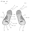
- FIG. 1 is a side view of a sock of the present invention.
- FIG. 2 is a plan view illustrating the soles of the left sock (a) and right sock (b) each having a heel portion 3, a sole portion 4 and a toe portion 6.
- This sock is designed for walking.
- the heel portion 3, which is subjected to a relatively heavy load, is composed of long-terry stitches LP
- the toe portion 6, which is subjected to a relatively light load is composed of short-terry stitches SP.
- the sole portion 4 is composed of short-terry stitches SP throughout.
- the front sole 4d i.e., the sole portion near the toes
- long-terry stitches with reinforcement yarn R-LP are partially exposed.
- short-terry stitches with reinforcement yarn R-SP are exposed in the form of projections between the rear sole.4b and the front sole 4d.
- the arch of the foot 4c is formed with short-terry stitches based on mesh stitches M-SP.
- the heel portion 3 which is subjected to the wearer's weight when he/she walks, with a cushioning effect.
- the toe portion 6, which needs to bend when walking, is made of short-terry stitches SP, whereas the front sole 4d, which is subjected to a kicking shock when walking, is partially provided with long-terry stitches with reinforcement yarn R-LP.
- the entire part of the sole area is provided with short-terry stitches SP so as to be able to withstand a medium-sized load and an airspace is formed between the sole of the foot and the insole of the sock.
- short-terry stitches with reinforcement yarn R-SP are distributed in the form of dotted protrusions.
- the arch portion 4c is provided with short-terry stitches based on mesh stitches M-SP.
- a sock having the above composition has terry stitches that are efficiently distributed according to the wearer's weight distribution. Such a sock absorbs the shock effectively when the wearer walks and assures excellent ventilation and transpiration of sweat, making it an ideal sock for light walking.
- the distribution of terries and knitting structures of different thicknesses can be varied according to the purpose for which the sock is used or to the season in which it is worn.
- the heel portion 3 and the toe portion 6 can also be provided with knitting structures of different thicknesses of terry stitches.
- FIGs. 3, 4, 5 and 6 illustrate other embodiments of the present invention.
- FIG. 3 is a side view showing an example of a sock designed for light mountaineering in the spring.
- the heel portion 3 of the sock 1 is composed of long-terry stitches LP.
- the narrowing course (the sole side of the gore line 6G) of the toe portion 6 is made of long-terry stitches LP so as to alleviate any shock to the ground-touching area at the toe portion of the sock 1 when walking downhill.
- the widening course (the instep side of the gore line 6G) is made of short-terry stitches SP.
- the sole portion 4 of the sock 1 is divided into a front sole 4d, composed of long-terry stitches based on mesh stitches M-LP, and a middle portion, composed of short-terry stitches based on reinforced mesh stitches M-R-SP, so as to achieve a cushioning effect and ventilation at the same time.
- the leg portion 2 is provided with a support 2a inlaid with elastic yarn, and the portion extending from the sole portion 4 including the arch to the instep side of the foot is also provided with a support 4a inlaid with elastic yarn.
- FIG. 4 is a plan view of the sole of a sock designed for jogging in spring and summer.
- the sock is for the left foot.
- the front sole 4d is made of a structure LP/SP combining long-terry stitches LP and short-terry stitches SP mixed in a pattern of dapples, and a portion of the sole 4 and the arch 4c of the foot are composed of a mesh M structure in order to ensure ventilation.
- the heel portion 3 and the rear sole 4b are made of long-terry stitches LP, while the toe portion 6 is made of short-terry stitches SP to facilitate light running.
- FIG. 5 is a plan view of the sole of a sock in which there is no distinction between the right sock and left sock (both having the same shape).
- This sock is designed for ordinary walking.
- the weight distribution over the entire area of the sole 4 is an important consideration.
- the front sole 4d is made of long-terry stitches LP, and a mesh M groove is formed in such a way as to form a space for capturing and retaining sweat.
- long-terry stitches based on reinforced mesh stitches M-R-LP are arranged in the front-to-rear direction in such a way as to form a space consisting of an air layer so as to reduce the fatigue of the sole of the foot.
- the heel 3 and the rear sole 4b are made of long-terry stitches LP and the toe portion 6 is composed of short-terry stitches SP.
- FIG. 6 is a plan view of a sock specifically designed for golfing.
- the heel portion 3 is composed of long-terry stitches LP in order to receive the load effectively
- the middle part of the sole 4 is composed of short-terry stitches with reinforcement yarn R-SP.
- long-terry stitch projections with reinforcement yarn R-LP are arranged like buttons in the front-to-rear direction of the sock.
- the front sole 4d which is subjected to a relatively heavy load, is composed of long-terry stitches LP and partially reinforced with long-terry projections with reinforcement yarn R-LP.
- the sock is provided with a support 4a inlaid with elastic yarn, which is further provided with long-terry stitches with reinforcement yarn R-LP in order to stabilize the foot and to form an air layer in it.
- the leg portion 2 and instep side 5 of the foot- may also be provided with various kinds of terry stitches of the present invention in order to design a sock with improved ventilation and foot protection.
- the wale number for the heel portion 3 of the sock may be increased to make a wide heel structure, or the narrowing and the widening of the toe portion 6 may be increased to make a Y gore line to further improve the sock's wearing performance, or more specifically, its fit and comfort.
- FIGS. 7, 8, 9 and 10 show examples of knitting structures according to the present invention.
- FIG. 7 shows a structure knitted of ground yarn (back yarn) Y1 and terry yarn Y2, in which short-terry stitches SP with long sinker loops of terry yarn Y2 and long-terry stitches LP with even longer sinker loops are knitted.
- FIG. 8 shows a mesh stitch structure in which terries are formed.
- the floating part F of terry yarn Y2 based on mesh stitches M is prolonged to form short-terry stitches based on mesh stitches M-SP and further prolonged to form long-terry stitches based on mesh stitches M-LP.
- FIG. 9 shows a structure made by knitting reinforcement yarn Y3 into the mesh structure terries of FIG. 8 Reinforcement yarn Y3 increases the thickness of the fabric and the floating part F of the terry yarn Y2 is prolonged to form short-terry stitches M-R-SP and further prolonged to form long-terry stitches M-R-LP.
- FIG. 10 shows a reinforced terry structure with reinforcement yarn Y3 made by further knitting reinforcement yarn Y3 into the structure shown in FIG. 7.
- the reinforcement yarn Y3 is knitted in a mesh stitch and floated F here and there, but the terry yarn Y2 is not floated and forms short-terry stitches R-SP and long-terry stitches R-LP.
- the structure in question can have a different terry-stitch length from those of other portions of the same area or of other areas.
- Terry stitches having different thicknesses and knitting spaces can be distributed according to different purposes.
- Test data of the thickness of different knitting structures are provided as examples in the following paragraph. These data have been obtained by measuring the absolute thickness of a structure knitted with 30/75s polyester and polyurethane covering yarn for the ground yam Y1, three strands of 32-count cotton and polyester synthetic yarn for the terry yarn Y2, and 110 denier nylon for the reinforcement yarn Y3, using a pressure-characteristics-measuring thickness gauge at a pressure of 10 gf/cm2.
- the thickness of the knitting structure depends on the type of knitting yarn used. By differentiating the thickness of the yarn for different parts of a sock, a variety of thicknesses can be obtained for different parts. In this way, by using a knitting structure of a different thickness, ventilation and air-holding gaps for a portion of at least one of the ground-touching areas, the sock can be provided with previously non-existent features.
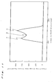
- FIG. 11 shows an example of changes in the reaction force from the floor to the sole changes when walking as measured by a floor-reaction meter.
- the horizontal axis represents time in units of 1/500th second
- the vertical axis represents the reaction from the floor in newtons.
- point A represents the instant at which the heel portion touches the floor. It is evident that a shock is imparted at this instant.
- Point B the entire area of the sole of the foot touches the ground. The shock is relatively weak and the reaction force from the floor fluctuates rapidly.
- Point C represents the instant at which the foot kicks the ground to generate thrust for walking. An impact is applied to the front sole 4d.
- the toe portion 6 is preferably formed with short-terry stitches SP so as to facilitate bending of the toes.
- FIG. 12 shows an example of a knitting method according to the present invention.
- the illustrations show parts of a circular sock-knitting machine in which knitting needles 10, a long-terry sinker 20L, a fixed plate 40 and a short-terry sinker 20S are visible.
- the long-terry sinker 20L, fixed plate 40 and short-terry sinker 20S are located between the two knitting needles 10.
- the long-terry sinker 20L is equipped with a high-terry sinker nib 27L for knitting long terries LP and the short-terry sinker 20S is equipped with a short-terry sinker nib 27S for knitting short terries SP.
- the knitting needle 10 descends (indicated by arrow B) activated by a stitch cam 80 and knits ground yarn Y and terry yarn Y2. Then the long-terry sinker 20L moves forward (indicated by arrow C). At this time the terry yarn Y2 rides on the high-terry nib 27L and forms a long sinker loop, i.e., a long terry LP. The short-terry sinker 20S is always in the forward position. When the long-terry sinker 20L does not move forward, the terry yarn Y2 rides on the low-terry nib 27S and forms a short sinker loop, i.e., a short terry SP.
- the fixed plate 40 has the function of separating the long-terry sinker 20L and the short-terry sinker 20S and preventing their mutual adhesion.
- the long-terry sinker 20L is equipped with a selector butt 21 for selecting whether or not to move the sinker forward (arrow C).
- An actuator head 71 receives a computer signal that decides whether or not to push the selector butt 21. This makes it possible to knit long-terry stitches LP in a "unit stitch for one stitch-loop" fashion in any portion of the fabric.
- short-terry sinker 20S It is also possible to equip the short-terry sinker 20S with a selector butt and to selectively move the short-terry sinker 20S.
- Terries can be knitted in ways other than by the method described above.
- a flat knitting machine or a circular knitting machine other than for socks can also be used to knit a sock of the present invention.
- reinforcement yarn Y3 By knitting reinforcement yarn Y3 simultaneously, short-terry stitches with reinforcement yarn R-SP and long-terry stitches with reinforcement yarn R-LP with varied terry-stitch thicknesses can be knitted.
- float stitches i.e., mesh stitches using pattern selecting of the knitting needles 10
- short-terry stitches based on mesh stitches M-SP and long-terry stitches based on mesh stitches M-LP can be knitted.
- reinforcement yarn Y3 in these stitches short-terry stitches based on reinforced mesh stitches M-R-SP and long-terry stitches based on reinforced mesh stitches M-R-LP can be knit
Abstract
Description
- The present invention relates to a sock in which a portion of at least one of the ground-touching areas of the sock, e.g., the heel portion, sole portion or toe portion, has a knitting structure of a different terry-stitch length from those of the other portions of the same area or of the other areas, according to the weight distribution on the sole, the shock distribution when walking or running, and the sweat-absorbing property required in different sports.
- Traditional terry socks have sole portions that are composed entirely of terry stitches. The purpose of this structure is, primarily, to warm the feet as well as to function as a shock absorber when walking or running. Because of this structure, the sole portion of the sock tends to be thick across its entire area, preventing the transpiration of sweat and in-shoe humidity, and causing a steamy feel. Moreover, because the sole portion is thick across its entire area, the wearer has to choose a shoe of a larger size than his/her actual foot size. In order to eliminate these characteristic flaws of the traditional terry sock, a sock having terry stitches distributed only over the necessary portions was conceived. This sock, known as a partial terry-stitch sock, is disclosed in
Patent Document 1.
[Patent Document 1] Unexamined Utility Model Application Publication No.S60-165405 - The sock disclosed in
Document 1 has, as described in its claims, "terry stitches distributed in different shapes for the left and right feet in accordance with the shapes of the feet and the shoes. The purpose of this sock is to provide compatibility with the shoe that is worn. The Document does not say anything about varying the thickness of the terry-stitch structure. When walking or running, the heel, sole and toe portions are subjected to different degrees of shock. Ideally each portion has a different terry-stitch thickness and cushion performance. In order to eliminate the flaws inDocument 1 above, different terry-stitch lengths may be used for different areas of the terry-stitch structure. A sock having such characteristics is disclosed inPatent Document 2.
[Patent Document 2] Utility Model Publication No.3037207 - The sock disclosed in
Document 2 above is, as described in itsclaim 2, "divided into two or more of the portions including the-inserting portion A, the calf portion B, the shin portion C, the heel portion D, the spur portion E, the sole portion F, the instep portion G and the toe portion H with each portion having a different terry length." For each section, i.e., area unit such as the heel portion and the sole portion, terry stitches of different terry lengths are formed. Within the same section, knitting structures of the same terry lengths are distributed. However, even within the same section, e.g., the sole portion, different areas are of different shapes and are subjected to different degrees of shock when walking or running. The sock disclosed inDocument 2 above cannot provide a cushion performance that complies with the ground-touching pressure distribution on the sole portion. Because the terry stitches have the same length within the same section, there is not enough space between the sole of the foot and the sock that eliminate the steamy feel.Patent Document 3 discloses a terry sock that provides increased ventilation.
[Patent Document 3] Unexamined Patent Application Publication No.2001-295104 - The sock disclosed in
Document 3, as described in itsclaim 1, has "an intermediate portion on the back of the sock where terry-stitched portions and plain-stitched portions are mixed." And as described in itsclaim 2, "the terry-stitched portions and plain-stitched portions are arranged in a grid." This structure simply incorporates terry stitches in the midst of plain stitches and does not provide a terry distribution or thickness that comply with the shape and ground-touching pressure of each portion of the sole.Patent Document 4 discloses a product having a variety of terry distributions.
[Patent Document 4] Unexamined Patent Application Publication No.H9-41202 - The sock disclosed in
Document 4 is, as described in itsclaim 1, a knit product having a terry-stitch portion characterized by terry loops formed on wales of choice by rotating the knitting cylinder in a reciprocating manner. Terry stitches, which are made through a clockwise rotation of the cylinder, and non-terry stitches, which are made through a counterclockwise rotation, are combined to form terries on the wales. In a clockwise rotation, terry stitches always appear on the same wales. Similarly, terry stitches appear on the same wales in a counter-clockwise rotation. The product made by this method does not have a terry-pressure distribution or terry thickness that corresponds to the shape of the sole or to the distribution of the foot pressure when the foot touches the ground as the wearer walks. - The present invention is aimed at overcoming the above drawbacks. The sock according to the present invention has at least one area within the ground-touching side of the sock, e.g., a heel portion, sole portion or toe portion where terry stitches of different terry-stitch lengths and shapes are evenly distributed in a "unit stitch for one stitch-loop" fashion.
The first objective of the present invention is to distribute terry stitches of a different thickness in at least one area within the ground-touching side of the sock, e.g., a heel portion, sole portion or toe portion, so as to match the weight distribution and shock experienced by the wearer as he/she walks or runs. The distribution reduces slippage between the sole of the foot, the sock and the insole of the shoe, thereby increasing the grip between the sole of the foot and the shoe. - The second objective of the present invention is to form different structures such as terry stitches, mesh stitches and/or reinforced stitches in at least one area of the ground-touching side of the sock so as to facilitate the absorption and transpiration of sweat according to the purpose of wearing the sock, e.g., sports, mountaineering, walking, etc.
- The third objective of the present invention is to improve the durability of the sock by using a terry-stitch structure reinforced with tough yarn material or synthetic fiber yarn for the parts that are prone to abrasion through contact with the shoe or subjected to the wearer's weight.
- The fourth objective of the present invention is to reduce the amount of yarn used by not distributing terry stitches in the areas where they are not necessary. This is achieved by setting appropriate terry-stitch length distributions according to the kinds of knitting yarn used.
- The fifth objective of the present invention is to make it easier for buyers to choose socks that suit their needs by using different yarn colors for portions of the sock having different terry-stitch lengths and knitting structures.
- The sixth objective of the present invention is to provide socks that are tailored to individual wearers by distributing terries of different thicknesses and meshes according to the shape of the foot and the mode of walking and running of the individual wearer.
- According to the present invention, a portion of at least one of the ground-touching areas of the sock has a knitting structure of a different terry-stitch length from those of the other portions of the same area or of the other areas. This makes it possible to alleviate shock and prevent slipping of the sock, making it a rational feature that is not found in conventional socks. It is also possible to provide socks that are appropriately designed for different purposes and seasons, for example, walking socks, jogging socks, mountain-climbing socks, golf socks, spring-and-summer socks and fall-and-winter socks, etc.
- Examples of knitting structures of different terry-stitch lengths include long-terry stitches LP and short-terry stitches SP. By varying the terry-stitch length only where necessary, contradicting objectives, i.e., reduction of the total amount of yarn used and assurance of the thickness of the sock and of adequate ventilation can be achieved at the same time.
- The long-terry-stitch LP portion may consist of a knitting structure made of long-terry stitches based on mesh stitches M-LP, long-terry stitches with reinforcement yarn R-LP or long-terry stitches based on reinforced mesh stitches M-R-LP. In this case, a portion within at least one of the ground-touching areas of the sock may consist of a knitting structure of mesh stitches that is different from those of the other portions of the same area or of the other areas, or of a structure of a different thickness, or simply thicker, than those of the other portions of the same area or of the other areas.
- The short-terry-stitch SP portion may consist of a knitting structure made of short-terry stitches based on mesh stitches M-SP, short-terry stitches with reinforcement yarn R-SP or short-terry stitches based on reinforced mesh stitches M-R-SP. In this case, a portion within at least one of the ground-touching areas of the sock may consist of a knitting structure of mesh stitches that is different from those of the other portions of the same area or of the other areas, or of a structure of a different thickness, or simply thicker, than those of the other portions of the same area or of the other areas.
- The sole side of the
gore line 6G of thetip 6 may of long-terry stitches LP and the instep side of thegore line 6G may be of short-terry stitches SP. This arrangement helps to alleviate the shock felt through the ground-touching area of the toe portion of the sock when walking or running on a downhill slope. - A certain portion of the sole 4 may be mixed with long-terry stitches LP and short-terry stitches SP in a "unit stitch for one stitch-loop" fashion. This improves the sock's ventilation and facilitates the absorption and transpiration of sweat.
- The
arch 4C of the foot on the sole 4 side may consist of a mesh structure so as to improve ventilation. This improves the sock's ventilation and facilitates the absorption and transpiration of sweat at thearch 4C of the foot. - The wale number (needle number) at the
heel 3 may be at least two thirds of the needle number for the whole in order to make an extended heel, and the gore lines on either side of thetoe 6 may form a Y shape. This improves the sock's performance, including its fit and comfort. - The reinforcement yarn Y3 and the terry yarn Y2 may be of different colors so that the reinforced part can be identified by its different color. In this way, buyers of the sock can tell the difference at a glance and select the sock that best suits their individual purpose. The use of different colors also has a design effect.
- According to the invention described in
claim 1, it is possible to achieve effective shock absorption that is not provided by conventional socks and to prevent sock-slippage. It is also possible to provide socks optimized for different purposes, such as walking, jogging, mountain climbing and golf, and for different seasons, such as spring/summer and fall/winter. - According to the invention described in
claim 2, it is possible to reduce yarn consumption and achieve conventionally conflicting features, i.e., a thicker sock and consistent ventilation by varying the terry length only where necessary. - According to the invention described in
claim 3, it is possible to provide a sock featuring optimum ground-touching pressure and shock distribution. By employing a terry-stitch structure with reinforcement yarn applied here and there, it is also possible to increase the durability of the sock. - According to the invention described in
claim 4, it is possible to provide a sock featuring improved ventilation and fit. Such a sock allows the formation of an airspace between the bottom of the foot and the insole of the sock and eliminates slippage between the foot and the sock. By employing a terry-stitch structure with reinforcement yarn applied here and there, it is also possible to increase the durability of the sock. - According to the invention described in
claim 5, it is possible to alleviate the shock felt through the ground-touching area of the toe portion of the sock when walking or running on a downhill slope. - According to the invention described in
claim 6, it is possible to provide the portion that mixes long-terry stitches LP and short-terry stitches SP in a "unit stitch for one stitch-loop" fashion with improved ventilation and absorption and transpiration of sweat. - According to the invention described in
claim 7, it is possible to improve the ventilation and the absorption and transpiration of sweat at the arch 4C of the foot. - According to the invention described in
claim 8, it is possible to improve the sock's performance including its fit and comfort. - According to the invention described in claim 9, buyers of the sock can tell the difference at a glance and select the sock that best suits their individual purpose. The use of different colors also has a design effect.
- The best mode of carrying out the present invention will now be explained by reference to an example.
Let us assume making a sock using a plain-stitch fabric having a thickness of 1. A long-terry stitch LP portion having a thickness of 2.5 to 3.5 and a short-terry stitch SP portion having a thickness of 1.5 to 2.4 are distributed at theheel portion 3,sole portion 4 andtoe portion 6 according to the distribution of the ground-touching pressures of thesock 1. A mesh portion M and a terry stitch portion that is thicker than the long-terry stitch LP portion and incorporating reinforcement yarn Y3 are arranged on thesole portion 4 according to the ground-touching pressure and shock distribution as well as in order to ensure ventilation for thesock 1. By distributing portions of different thicknesses as in this example, it is possible to make a sock that suits different purposes and seasons. - FIG. 1 is a side view of a sock of the present invention. FIG. 2 is a plan view illustrating the soles of the left sock (a) and right sock (b) each having a
heel portion 3, asole portion 4 and atoe portion 6. This sock is designed for walking. Theheel portion 3, which is subjected to a relatively heavy load, is composed of long-terry stitches LP, and thetoe portion 6, which is subjected to a relatively light load, is composed of short-terry stitches SP. Thesole portion 4 is composed of short-terry stitches SP throughout. In the front sole 4d (i.e., the sole portion near the toes), long-terry stitches with reinforcement yarn R-LP are partially exposed. Along the left side of the sole, short-terry stitches with reinforcement yarn R-SP are exposed in the form of projections between the rear sole.4b and the front sole 4d. The arch of thefoot 4c is formed with short-terry stitches based on mesh stitches M-SP. - By arranging the different portions of the sock as described above, it is possible to provide the
heel portion 3, which is subjected to the wearer's weight when he/she walks, with a cushioning effect. Thetoe portion 6, which needs to bend when walking, is made of short-terry stitches SP, whereas the front sole 4d, which is subjected to a kicking shock when walking, is partially provided with long-terry stitches with reinforcement yarn R-LP. Preferably the entire part of the sole area is provided with short-terry stitches SP so as to be able to withstand a medium-sized load and an airspace is formed between the sole of the foot and the insole of the sock. In order to eliminate slippage between the foot and the sock, short-terry stitches with reinforcement yarn R-SP are distributed in the form of dotted protrusions. In addition, in order to improve the ventilation of thearch portion 4c and allow the sock to contact the foot lightly, thearch portion 4c is provided with short-terry stitches based on mesh stitches M-SP. - A sock having the above composition has terry stitches that are efficiently distributed according to the wearer's weight distribution. Such a sock absorbs the shock effectively when the wearer walks and assures excellent ventilation and transpiration of sweat, making it an ideal sock for light walking. The distribution of terries and knitting structures of different thicknesses can be varied according to the purpose for which the sock is used or to the season in which it is worn. Depending on the purpose, the
heel portion 3 and thetoe portion 6 can also be provided with knitting structures of different thicknesses of terry stitches. - FIGs. 3, 4, 5 and 6 illustrate other embodiments of the present invention.
FIG. 3 is a side view showing an example of a sock designed for light mountaineering in the spring. Theheel portion 3 of thesock 1 is composed of long-terry stitches LP. The narrowing course (the sole side of thegore line 6G) of thetoe portion 6 is made of long-terry stitches LP so as to alleviate any shock to the ground-touching area at the toe portion of thesock 1 when walking downhill. The widening course (the instep side of thegore line 6G) is made of short-terry stitches SP. Thesole portion 4 of thesock 1 is divided into a front sole 4d, composed of long-terry stitches based on mesh stitches M-LP, and a middle portion, composed of short-terry stitches based on reinforced mesh stitches M-R-SP, so as to achieve a cushioning effect and ventilation at the same time. In order to give thesock 1 firmer leg support, theleg portion 2 is provided with asupport 2a inlaid with elastic yarn, and the portion extending from thesole portion 4 including the arch to the instep side of the foot is also provided with a support 4a inlaid with elastic yarn. - FIG. 4 is a plan view of the sole of a sock designed for jogging in spring and summer. The sock is for the left foot. In the case of jogging, ventilation and absorption and transpiration of sweat are important considerations. Accordingly, the front sole 4d is made of a structure LP/SP combining long-terry stitches LP and short-terry stitches SP mixed in a pattern of dapples, and a portion of the sole 4 and the arch 4c of the foot are composed of a mesh M structure in order to ensure ventilation. In order to optimize the load from running, the
heel portion 3 and the rear sole 4b are made of long-terry stitches LP, while thetoe portion 6 is made of short-terry stitches SP to facilitate light running. - FIG. 5 is a plan view of the sole of a sock in which there is no distinction between the right sock and left sock (both having the same shape). This sock is designed for ordinary walking. In the case of ordinary walking, the weight distribution over the entire area of the sole 4 is an important consideration. Accordingly, the front sole 4d is made of long-terry stitches LP, and a mesh M groove is formed in such a way as to form a space for capturing and retaining sweat. In the middle of the sole 4, long-terry stitches based on reinforced mesh stitches M-R-LP are arranged in the front-to-rear direction in such a way as to form a space consisting of an air layer so as to reduce the fatigue of the sole of the foot. The
heel 3 and the rear sole 4b are made of long-terry stitches LP and thetoe portion 6 is composed of short-terry stitches SP. - FIG. 6 is a plan view of a sock specifically designed for golfing. In the case of golfing, the cushion on the ground-touching area and the grip between the shoe, sock and sole of the foot when playing are both important. The
heel portion 3 is composed of long-terry stitches LP in order to receive the load effectively, and the middle part of the sole 4 is composed of short-terry stitches with reinforcement yarn R-SP. In order to provide the sole of the foot with a grip, long-terry stitch projections with reinforcement yarn R-LP are arranged like buttons in the front-to-rear direction of the sock. The front sole 4d, which is subjected to a relatively heavy load, is composed of long-terry stitches LP and partially reinforced with long-terry projections with reinforcement yarn R-LP. In order to prevent slippage, the sock is provided with a support 4a inlaid with elastic yarn, which is further provided with long-terry stitches with reinforcement yarn R-LP in order to stabilize the foot and to form an air layer in it. - Portions other than the
heel 3, sole 4 and toe 6-specifically, theleg portion 2 andinstep side 5 of the foot-may also be provided with various kinds of terry stitches of the present invention in order to design a sock with improved ventilation and foot protection.
The wale number for theheel portion 3 of the sock may be increased to make a wide heel structure, or the narrowing and the widening of thetoe portion 6 may be increased to make a Y gore line to further improve the sock's wearing performance, or more specifically, its fit and comfort. - FIGS. 7, 8, 9 and 10 show examples of knitting structures according to the present invention.
FIG. 7 shows a structure knitted of ground yarn (back yarn) Y1 and terry yarn Y2, in which short-terry stitches SP with long sinker loops of terry yarn Y2 and long-terry stitches LP with even longer sinker loops are knitted. - FIG. 8 shows a mesh stitch structure in which terries are formed. For example, the floating part F of terry yarn Y2 based on mesh stitches M is prolonged to form short-terry stitches based on mesh stitches M-SP and further prolonged to form long-terry stitches based on mesh stitches M-LP.
- FIG. 9 shows a structure made by knitting reinforcement yarn Y3 into the mesh structure terries of FIG. 8 Reinforcement yarn Y3 increases the thickness of the fabric and the floating part F of the terry yarn Y2 is prolonged to form short-terry stitches M-R-SP and further prolonged to form long-terry stitches M-R-LP.
- FIG. 10 shows a reinforced terry structure with reinforcement yarn Y3 made by further knitting reinforcement yarn Y3 into the structure shown in FIG. 7. The reinforcement yarn Y3 is knitted in a mesh stitch and floated F here and there, but the terry yarn Y2 is not floated and forms short-terry stitches R-SP and long-terry stitches R-LP.
- As described above, by incorporating terries in a mesh-stitch structure or a knitting structure with reinforcement in a portion of at least one of the ground-touching areas of a sock, the structure in question can have a different terry-stitch length from those of other portions of the same area or of other areas. Terry stitches having different thicknesses and knitting spaces can be distributed according to different purposes.
- As has been explained, in the present invention, different structures made of plain stitches P, short-terry stitches SP, long-terry stitches LP, meshes M, short-terry stitches based on mesh stitches M-SP, long-terry stitches based on mesh stitches M-LP, short-terry stitches based on reinforced mesh stitches M-R-SP, long-terry stitches based on reinforced mesh stitches M-R-LP, short-terry stitches with reinforcement yarn R-SP or long-terry stitches with reinforcement yarn R-LP and having different thicknesses and gap ratios are distributed in a portion within at least one of the ground-touching areas of the sock. In this way, it is possible to design and make available for users a sock that is optimized for the purpose and for the season in which it is used.
- Test data of the thickness of different knitting structures are provided as examples in the following paragraph. These data have been obtained by measuring the absolute thickness of a structure knitted with 30/75s polyester and polyurethane covering yarn for the ground yam Y1, three strands of 32-count cotton and polyester synthetic yarn for the terry yarn Y2, and 110 denier nylon for the reinforcement yarn Y3, using a pressure-characteristics-measuring thickness gauge at a pressure of 10 gf/cm2.
-
[Table 1] Knitting structure Code Thickness mm 1 Plain stitch P 1.40 2 Short-terry stitch SP 2.86 3 Long-terry stitch LP 4.05 4 Mesh M 1.31 5 Short-terry stitch based on mesh stitch M-SP 1.69 6 Long-terry stitch based on mesh stitch M-LP 3.01 7 Short-terry stitch based on reinforced mesh stitches M-R-SP 3.53 8 Long-terry stitch based on reinforced mesh stitches M-R-LP 4.27 9 Short-terry stitch with reinforcement yarn R-SP 3.40 10 Long-terry stitch with reinforcement yarn R-LP 4.14 - The thickness of the knitting structure depends on the type of knitting yarn used. By differentiating the thickness of the yarn for different parts of a sock, a variety of thicknesses can be obtained for different parts. In this way, by using a knitting structure of a different thickness, ventilation and air-holding gaps for a portion of at least one of the ground-touching areas, the sock can be provided with previously non-existent features.
- FIG. 11 shows an example of changes in the reaction force from the floor to the sole changes when walking as measured by a floor-reaction meter.
In this graph, the horizontal axis represents time in units of 1/500th second, and the vertical axis represents the reaction from the floor in newtons. In this graph, point A represents the instant at which the heel portion touches the floor. It is evident that a shock is imparted at this instant. At point B, the entire area of the sole of the foot touches the ground. The shock is relatively weak and the reaction force from the floor fluctuates rapidly. Point C represents the instant at which the foot kicks the ground to generate thrust for walking. An impact is applied to the front sole 4d.
From the above observations, it is evident that for an ordinary walking sock, the best effect is achieved by distributing long-terry stitches LP to theheel portion 3 and short-terry stitches to thesole portion 4 and partially including long-terry stitches with reinforcement yarn R-LP in the front sole 4d. Thetoe portion 6 is preferably formed with short-terry stitches SP so as to facilitate bending of the toes. - FIG. 12 shows an example of a knitting method according to the present invention. The illustrations show parts of a circular sock-knitting machine in which
knitting needles 10, a long-terry sinker 20L, a fixedplate 40 and a short-terry sinker 20S are visible. The long-terry sinker 20L, fixedplate 40 and short-terry sinker 20S are located between the twoknitting needles 10. The long-terry sinker 20L is equipped with a high-terry sinker nib 27L for knitting long terries LP and the short-terry sinker 20S is equipped with a short-terry sinker nib 27S for knitting short terries SP. - The
knitting needle 10 descends (indicated by arrow B) activated by astitch cam 80 and knits ground yarn Y and terry yarn Y2. Then the long-terry sinker 20L moves forward (indicated by arrow C). At this time the terry yarn Y2 rides on the high-terry nib 27L and forms a long sinker loop, i.e., a long terry LP.
The short-terry sinker 20S is always in the forward position. When the long-terry sinker 20L does not move forward, the terry yarn Y2 rides on the low-terry nib 27S and forms a short sinker loop, i.e., a short terry SP. The fixedplate 40 has the function of separating the long-terry sinker 20L and the short-terry sinker 20S and preventing their mutual adhesion.
The long-terry sinker 20L is equipped with aselector butt 21 for selecting whether or not to move the sinker forward (arrow C). Anactuator head 71 receives a computer signal that decides whether or not to push theselector butt 21. This makes it possible to knit long-terry stitches LP in a "unit stitch for one stitch-loop" fashion in any portion of the fabric. - It is also possible to equip the short-
terry sinker 20S with a selector butt and to selectively move the short-terry sinker 20S. Terries can be knitted in ways other than by the method described above. A flat knitting machine or a circular knitting machine other than for socks can also be used to knit a sock of the present invention.
By knitting reinforcement yarn Y3 simultaneously, short-terry stitches with reinforcement yarn R-SP and long-terry stitches with reinforcement yarn R-LP with varied terry-stitch thicknesses can be knitted. By performing float stitches, i.e., mesh stitches using pattern selecting of theknitting needles 10, short-terry stitches based on mesh stitches M-SP and long-terry stitches based on mesh stitches M-LP can be knitted. By further knitting reinforcement yarn Y3 in these stitches, short-terry stitches based on reinforced mesh stitches M-R-SP and long-terry stitches based on reinforced mesh stitches M-R-LP can be knitted. -
- FIG. 1 is a side view showing an example of a sock of the present invention.
- FIG. 2 is a plan view showing the bottom of the sock shown in FIG. 1. (a) is for the left foot and (b) is for the right foot.
- FIG. 3 is a side view of an example of a sock designed for light mountaineering in spring and summer, which is an embodiment of the present invention.
- FIG. 4 is a plan view of the bottom of a left sock designed for jogging in spring and summer, which is an embodiment of the present invention.
- FIG. 5 is a plan view of the bottom of a sock, which can be worn on the left foot or right foot so it is convenient for ordinary walking, which is an embodiment of the present invention.
- FIG. 6 is a plan view of the bottom of a sock suitable for golfing, which is an embodiment of the present invention.
- FIG. 7 shows an example of a knitting structure of a sock of the present invention, which is knitted with ground yarn (back yarn) and terry yarn. The terry yarn has some sinker loops that are prolonged to form short terries and other sinker loops that are further prolonged to form long terries.
- FIG. 8 shows an example of a knitting structure of a sock of the present invention, in which the mesh terry yarn has some floating parts that are prolonged to form short terries and other floating parts that are further prolonged to form long terries.
- FIG. 9 shows an example of a knitting structure of a sock of the present invention, in which reinforcement yarn is used to increase the thickness of the knitting structure, and the terry yarn has some floats that are prolonged to form short terries and other floats that are further prolonged to form long terries.
- FIG. 10 shows an example of a knitting structure of a sock of the present invention, in which reinforcement yarn is further knitted in the structure of FIG. 7 to make it a terry-stitch structure with reinforcement yarn.
- FIG. 11 is a graph showing an example of a measurement of the reaction force from the floor applied to the bottom of the foot when walking.
- FIG. 12 is a perspective view illustrating an example of a sock-knitting method of the present invention.
-
- 1: sock
- 2: leg
- 2a: support of the leg portion
- 3: heel
- 3G: gore line of the heel
- 4: sole portion
- 4a: support of the sole portion
- 4b: the rear sole
- 4c: the arch of the foot
- 4d: the front sole (sole portion near the toes)
- 5: instep side of the foot
- 6: toe portion
- 6G: gore line of the toe
- 10: knitting needle
- 20L: long-terry sinker
- 20S: short-terry sinker
- 21: selector butts
- 27L: high-terry sinker nib
- 27S: low-terry sinker nib
- 40: fixed plate
- 71: the head of the actuator
- 80: stitch cam
- Y1: ground yarn
- Y2: terry yarn
- Y3: reinforcement yarn
- P: plain stitches
- SP: short-terry stitches
- LP: long-terry stitches
- M: mesh stitches
- F: float stitch(es)
- M-SP: short-terry stitches based on mesh stitches
- M-LP: long-terry stitches based on mesh stitches
- M-R-SP: short-terry stitches based on reinforced mesh stitches
- M-R-LP: long-terry stitches based on reinforced mesh stitches
- R-SP: short-terry stitches with reinforcement yarn
- R-LP: long-terry stitches with reinforcement yarn
Claims (9)
- A terry sock of a multi-stitch-length structure in which a portion of at least one of the ground-touching areas of the sock has a knitting structure of a different terry-stitch length from those of the other portions of the same area or of the other areas.
- A terry sock of a multi-stitch-length structure according to Claim 1 in which the knitting structure of a different terry-stitch length is composed of either long-terry stitches LP or short-terry stitches SP.
- A terry sock of a multi-stitch-length structure according to Claim 2 in which the long-terry LP stitch part is composed of a knitting structure made of long-terry stitches based on mesh stitches M-LP, long-terry stitches with reinforcement yarn R-LP or long-terry stitches based on reinforced mesh stitches M-R-LP.
- A terry sock of a multi-stitch-length structure according to Claim 2 in which the short-terry SP stitch part is composed of a knitting structure made of short-terry stitches based on short stitches M-SP, short-terry stitches with reinforcement yarn R-SP or short-terry stitches based on reinforced mesh stitches M-R-SP.
- A terry sock of a multi-stitch-length structure according to Claim 1 or 2 in which the sole side of the gore line 6G of the toe 6 is composed of long-terry stitches LP and the instep side of the gore line 6G is composed of short-terry stitches SP.
- A terry sock of a multi-stitch-length structure according to Claim 1 or 2 in which the long-terry stitches LP and short-terry stitches SP are mixed in a certain part of the sole portion 4 in a "unit stitch for one stitch-loop" fashion.
- A terry sock of a multi-stitch-length structure according to any of Claims 1 to 6 in which the arch of the foot 4C of the sole portion 4 has a structure composed of mesh stitches for improved ventilation.
- A terry sock of a multi-stitch-length structure according to any of Claims 2 to 6 in which the wale number (needle number) at the heel portion 3 is at least two thirds of the needle number for the whole to make an extended heel, and the gore lines on either side of the toe 6 form a Y-shape.
- A terry-sock of a multi-stitch-length structure according to any of Claims 3 to 6 in which reinforcement yarn Y3 and terry yarn Y2 of different colors are used so that the reinforced portions can be identified by their difference in color.
Applications Claiming Priority (2)
| Application Number | Priority Date | Filing Date | Title |
|---|---|---|---|
| JP2004285711A JP4502768B2 (en) | 2004-09-30 | 2004-09-30 | Multi-pile socks |
| PCT/JP2005/016303 WO2006038415A1 (en) | 2004-09-30 | 2005-09-06 | Socks of multi-stage pile structure |
Publications (3)
| Publication Number | Publication Date |
|---|---|
| EP1813159A1 true EP1813159A1 (en) | 2007-08-01 |
| EP1813159A4 EP1813159A4 (en) | 2013-08-14 |
| EP1813159B1 EP1813159B1 (en) | 2018-01-17 |
Family
ID=36142497
Family Applications (1)
| Application Number | Title | Priority Date | Filing Date |
|---|---|---|---|
| EP05781939.3A Expired - Fee Related EP1813159B1 (en) | 2004-09-30 | 2005-09-06 | Socks of multi-stage pile structure |
Country Status (5)
| Country | Link |
|---|---|
| US (1) | US7677061B2 (en) |
| EP (1) | EP1813159B1 (en) |
| JP (1) | JP4502768B2 (en) |
| CN (1) | CN100566611C (en) |
| WO (1) | WO2006038415A1 (en) |
Cited By (12)
| Publication number | Priority date | Publication date | Assignee | Title |
|---|---|---|---|---|
| EP1997394A1 (en) * | 2007-05-26 | 2008-12-03 | FALKE KGaA | Leg clothing |
| WO2009130052A1 (en) * | 2008-04-25 | 2009-10-29 | Oliver Hasenfuhs | Sock, particularly athletic or hiking sock |
| WO2011138613A1 (en) * | 2010-05-05 | 2011-11-10 | Drew Brady & Co. Limited | Sinker for manufacturing clothing |
| CN103255561A (en) * | 2012-02-15 | 2013-08-21 | 冈本株式会社 | Knitting machine capable of changing pile length and manufacturing method of knitted fabric having different pile lengths |
| EP2116642A4 (en) * | 2006-12-22 | 2014-01-08 | Shima Seiki Mfg | Knitting method of heel parts of socks |
| CN103826484A (en) * | 2011-08-25 | 2014-05-28 | X-技术瑞士有限公司 | Sock |
| EP1994839A4 (en) * | 2006-02-03 | 2015-05-06 | Unival Co Ltd | Sock |
| CN105996284A (en) * | 2015-03-31 | 2016-10-12 | 阿迪达斯股份公司 | Shoe upper for sports shoes |
| WO2017072191A1 (en) * | 2015-10-27 | 2017-05-04 | Birkenstock Sales GmbH | Sock comprising stimulation elements |
| CN106805298A (en) * | 2017-04-08 | 2017-06-09 | 海宁汉德袜业有限公司 | Anti-skidding the five fingers Yoga socks |
| WO2018089501A1 (en) * | 2016-11-08 | 2018-05-17 | Nike Innovate C.V. | Articles with integrally knit heat-treatable yarn |
| EP3569748A1 (en) * | 2018-05-01 | 2019-11-20 | TBL Licensing LLC | Knit with multi-density knit zone |
Families Citing this family (62)
| Publication number | Priority date | Publication date | Assignee | Title |
|---|---|---|---|---|
| US20060218701A1 (en) * | 2005-03-31 | 2006-10-05 | Liberman Barnet L | Ski sock |
| CN100559978C (en) * | 2006-02-08 | 2009-11-18 | 冈本株式会社 | Socks |
| WO2008065671A2 (en) * | 2006-12-01 | 2008-06-05 | Nike International Ltd. | A sock and a method for its manufacture |
| JP4825119B2 (en) * | 2006-12-06 | 2011-11-30 | 岡本株式会社 | Socks and manufacturing method thereof |
| JP5086760B2 (en) * | 2007-10-10 | 2012-11-28 | 岡本株式会社 | socks |
| JP5102611B2 (en) * | 2007-12-27 | 2012-12-19 | 岡本株式会社 | socks |
| JP5558691B2 (en) * | 2008-10-29 | 2014-07-23 | グンゼ株式会社 | Socks and manufacturing method thereof |
| TW201143646A (en) * | 2010-01-22 | 2011-12-16 | Kowa Co | Foot wear |
| WO2011143369A2 (en) * | 2010-05-11 | 2011-11-17 | Columbia Sportswear North America, Inc. | Performance sock |
| US20110277217A1 (en) * | 2010-05-14 | 2011-11-17 | Yoo David | Seamless sock and method of knitting the same |
| JP5269835B2 (en) * | 2010-06-11 | 2013-08-21 | 岡本株式会社 | socks |
| WO2012032457A2 (en) | 2010-09-07 | 2012-03-15 | Delta Galil Industries Ltd. | Socks, and system and method for manufacturing socks |
| US9961943B2 (en) * | 2010-11-03 | 2018-05-08 | F3 Tech, Llc | Athletic sock |
| US8572766B2 (en) * | 2011-01-14 | 2013-11-05 | Bear In Mind Company | Socks having areas of varying stretchability and methods of manufacturing same |
| KR101282148B1 (en) | 2011-10-12 | 2013-07-04 | 박영식 | Toe socks and knitting method thereof |
| JP6106865B2 (en) * | 2012-02-15 | 2017-04-05 | 岡本株式会社 | Knitted fabric with varying pile length, knitted products and socks |
| CN103255562B (en) * | 2012-02-15 | 2015-11-25 | 冈本株式会社 | The manufacture method of the knitting machine that coil dimension is controlled and knit fabric |
| US20130256934A1 (en) * | 2012-03-30 | 2013-10-03 | Deckers Outdoor Corporation | Method of manufacturing a wool pile fabric product |
| US9297097B2 (en) * | 2012-06-22 | 2016-03-29 | Nike, Inc. | Knit article of apparel and apparel printing system and method |
| KR101690525B1 (en) * | 2012-07-17 | 2016-12-28 | 가부시키가이샤 시마세이키 세이사쿠쇼 | Shoe upper and method for producing shoe upper |
| US20140311187A1 (en) * | 2013-03-15 | 2014-10-23 | Ministry Of Supply | Performance dress sock |
| DE102013207156A1 (en) | 2013-04-19 | 2014-10-23 | Adidas Ag | Shoe, in particular a sports shoe |
| DE102013207155B4 (en) | 2013-04-19 | 2020-04-23 | Adidas Ag | Shoe upper |
| DE102013207153B4 (en) * | 2013-04-19 | 2019-11-07 | Adidas Ag | Shoe adapted to the foot shape |
| DE102013207163B4 (en) * | 2013-04-19 | 2022-09-22 | Adidas Ag | shoe upper |
| US11666113B2 (en) | 2013-04-19 | 2023-06-06 | Adidas Ag | Shoe with knitted outer sole |
| US10299531B2 (en) * | 2013-05-14 | 2019-05-28 | Nike, Inc. | Article of footwear incorporating a knitted component for a heel portion of an upper |
| JP6214934B2 (en) * | 2013-06-10 | 2017-10-18 | 美津濃株式会社 | socks |
| JP2015010298A (en) * | 2013-06-27 | 2015-01-19 | 岡本株式会社 | Legwear |
| USD752334S1 (en) | 2013-09-12 | 2016-03-29 | Hbi Branded Apparel Enterprises, Llc | Sock with arch support |
| JP5749774B2 (en) * | 2013-09-30 | 2015-07-15 | 美津濃株式会社 | shoes |
| US11576441B2 (en) | 2014-01-22 | 2023-02-14 | Soksystem, Llc | Sock with support assemblage |
| US9439457B2 (en) | 2014-01-22 | 2016-09-13 | Soksystem, Llc | Arch-supporting sock |
| DE102014202432B4 (en) | 2014-02-11 | 2017-07-27 | Adidas Ag | Improved football boot |
| KR101448545B1 (en) * | 2014-08-04 | 2014-10-14 | 정용석 | The traditional korean socks |
| DE102014220087B4 (en) | 2014-10-02 | 2016-05-12 | Adidas Ag | Flat knitted shoe top for sports shoes |
| TWI570293B (en) * | 2014-12-15 | 2017-02-11 | Da Kong Enterprise Co Ltd | Socks suture method and structure |
| US20160367182A1 (en) * | 2015-06-16 | 2016-12-22 | Empire Technology Development Llc | Perspiration monitoring |
| US10034497B1 (en) * | 2015-07-08 | 2018-07-31 | Rhonda G. Jackson | Infant/toddler sock system |
| US20170035120A1 (en) * | 2015-08-03 | 2017-02-09 | Tbl Licensing Llc | Sock with selective yarn placement |
| CN107028223A (en) * | 2016-02-03 | 2017-08-11 | 海宁市越立袜业有限公司 | A kind of sports socks |
| USD841965S1 (en) | 2016-12-08 | 2019-03-05 | Cels Enterprises, Inc. | Shoe outer sole |
| US10385486B2 (en) | 2017-02-06 | 2019-08-20 | Nike, Inc. | Garment for foot with triangular ankle panels |
| EP3375921A1 (en) * | 2017-03-15 | 2018-09-19 | medi GmbH & Co. KG | Knitted piece |
| US20190029331A1 (en) * | 2017-07-26 | 2019-01-31 | Zenobie Field | Sock with Trigonomic Arch Support |
| JP6284256B1 (en) * | 2017-11-20 | 2018-02-28 | 西垣靴下株式会社 | socks |
| EP3781737A1 (en) * | 2018-04-16 | 2021-02-24 | Nike Innovate C.V. | A shoe upper comprising knitted cushion regions and an article of footwear incorporating same |
| US11180874B2 (en) * | 2018-04-20 | 2021-11-23 | Mast Industries (Far East) Limited | Garment with higher coefficient of friction when stretched |
| WO2019224846A1 (en) * | 2018-05-25 | 2019-11-28 | FEETNESS S.r.l. | Containing fabric, garments comprising such fabric, and related production methods |
| CN108660596A (en) * | 2018-05-25 | 2018-10-16 | 银川瑞纳服饰有限公司 | A kind of method for weaving of anti-skidding running socks |
| CN108950845B (en) * | 2018-07-23 | 2020-06-30 | 福建荣荣新材料股份有限公司 | Knitting method of hosiery machine fabric with mesh structure |
| US11272745B2 (en) | 2019-01-14 | 2022-03-15 | Nike, Inc. | Sock with integrally knit grip strips of varying widths |
| CN111455531B (en) * | 2020-05-13 | 2024-04-02 | 信泰(福建)科技有限公司 | Imitation leather grass fabric, imitation leather grass vamp and imitation leather grass fabric manufacturing method |
| CN111850785A (en) * | 2020-06-30 | 2020-10-30 | 陕西科技大学 | Weaving method of breathable moisture-conducting quick-drying socks |
| US20220125129A1 (en) * | 2020-10-28 | 2022-04-28 | Lululemon Athletica Canada Inc. | Socks having targeted cushioning zones |
| CN116685732A (en) * | 2020-12-31 | 2023-09-01 | 耐克创新有限合伙公司 | Sports sock |
| CN116670347A (en) * | 2020-12-31 | 2023-08-29 | 耐克创新有限合伙公司 | Knitted article with variable features |
| US11882886B2 (en) * | 2020-12-31 | 2024-01-30 | Nike, Inc. | Athletic sock |
| USD1017221S1 (en) * | 2021-04-14 | 2024-03-12 | Tbl Licensing Llc | Sock |
| USD1015724S1 (en) | 2021-04-14 | 2024-02-27 | Tbl Licensing Llc | Sock |
| USD1015725S1 (en) | 2021-04-14 | 2024-02-27 | Tbl Licensing Llc | Sock |
| JP7426523B1 (en) | 2023-05-31 | 2024-02-01 | 西垣靴下株式会社 | socks |
Citations (3)
| Publication number | Priority date | Publication date | Assignee | Title |
|---|---|---|---|---|
| US4732015A (en) * | 1985-10-23 | 1988-03-22 | American Doubloon Corporation | Knitted article |
| US5335517A (en) * | 1993-07-23 | 1994-08-09 | James L. Throneburg | Anatomical isotonic sock and method of knitting the same |
| JP2003138401A (en) * | 2001-10-30 | 2003-05-14 | Nagata Seiki Co Ltd | Sock |
Family Cites Families (25)
| Publication number | Priority date | Publication date | Assignee | Title |
|---|---|---|---|---|
| JPS5812922B2 (en) * | 1979-04-02 | 1983-03-10 | 東洋繊維株式会社 | sports socks |
| US4253317A (en) * | 1979-04-26 | 1981-03-03 | Burlington Industries, Inc. | Sock construction |
| US4255949A (en) * | 1979-08-16 | 1981-03-17 | Thorneburg James L | Athletic socks with integrally knit arch cushion |
| JPS57150507U (en) * | 1981-03-18 | 1982-09-21 | ||
| JPS57180708A (en) | 1981-04-30 | 1982-11-06 | Bridgestone Corp | Falling device for flexible film dam |
| JPS57180708U (en) * | 1981-05-07 | 1982-11-16 | ||
| JPS5923603B2 (en) | 1981-09-07 | 1984-06-04 | 敬 森 | photoelectric lighting device |
| JPS5842104U (en) * | 1981-09-10 | 1983-03-19 | 岡山株式会社 | double pile socks |
| JPS5868904A (en) | 1981-10-20 | 1983-04-25 | 三菱電機株式会社 | Method of producing voltage nonlinear resistor |
| JPS5868904U (en) * | 1981-11-02 | 1983-05-11 | 岩崎 正一 | socks for hard court |
| US4392031A (en) | 1981-12-31 | 1983-07-05 | Bell Telephone Laboratories, Incorporated | Miniature electrical switch |
| JPS58115723U (en) * | 1982-01-28 | 1983-08-08 | 岡本株式会社 | pile socks |
| JPS60165405A (en) | 1984-02-07 | 1985-08-28 | Matsushita Electric Ind Co Ltd | Combustion apparatus |
| JPS6433507U (en) * | 1987-08-24 | 1989-03-01 | ||
| JPH0337207U (en) | 1989-08-19 | 1991-04-11 | ||
| US5560226A (en) * | 1995-01-12 | 1996-10-01 | Throneburg; James L. | Foot protector in combination with hosiery and method of knitting same |
| JPH0941202A (en) | 1995-07-31 | 1997-02-10 | Yamamoto:Kk | Knit product having pile stitch part |
| US5713220A (en) * | 1995-07-31 | 1998-02-03 | Nagata Seiki Kabushiki Kaisha | Pile patterning mechanism for circular knitting machine and knitted article knitted by the circular knitting machine |
| US5603232A (en) * | 1995-11-22 | 1997-02-18 | Throneburg; James L. | Foot protector for use in combination with hosiery and method of making and using same |
| US5791163A (en) * | 1996-09-26 | 1998-08-11 | Throneburg; James L. | Knit foot protector having integral padding and method of knitting same |
| JP3037207B2 (en) * | 1997-05-23 | 2000-04-24 | 日本電気株式会社 | LSI test method |
| JP3314071B2 (en) * | 2000-04-10 | 2002-08-12 | 株式会社藤本コーポレーション | Pile socks |
| US6230525B1 (en) * | 2000-05-04 | 2001-05-15 | Albert Ray Dunlap | Sock with impact absorbing sole and method |
| JP3809778B2 (en) * | 2001-06-12 | 2006-08-16 | 株式会社ナイガイ | Foot cover knitting method |
| JP2003119601A (en) | 2001-10-16 | 2003-04-23 | Renaun:Kk | Socks |
-
2004
- 2004-09-30 JP JP2004285711A patent/JP4502768B2/en not_active Expired - Fee Related
-
2005
- 2005-09-06 US US11/663,931 patent/US7677061B2/en not_active Expired - Fee Related
- 2005-09-06 EP EP05781939.3A patent/EP1813159B1/en not_active Expired - Fee Related
- 2005-09-06 WO PCT/JP2005/016303 patent/WO2006038415A1/en active Application Filing
- 2005-09-06 CN CNB2005800297002A patent/CN100566611C/en not_active Expired - Fee Related
Patent Citations (3)
| Publication number | Priority date | Publication date | Assignee | Title |
|---|---|---|---|---|
| US4732015A (en) * | 1985-10-23 | 1988-03-22 | American Doubloon Corporation | Knitted article |
| US5335517A (en) * | 1993-07-23 | 1994-08-09 | James L. Throneburg | Anatomical isotonic sock and method of knitting the same |
| JP2003138401A (en) * | 2001-10-30 | 2003-05-14 | Nagata Seiki Co Ltd | Sock |
Non-Patent Citations (1)
| Title |
|---|
| See also references of WO2006038415A1 * |
Cited By (25)
| Publication number | Priority date | Publication date | Assignee | Title |
|---|---|---|---|---|
| EP1994839A4 (en) * | 2006-02-03 | 2015-05-06 | Unival Co Ltd | Sock |
| EP2116642A4 (en) * | 2006-12-22 | 2014-01-08 | Shima Seiki Mfg | Knitting method of heel parts of socks |
| EP1997394A1 (en) * | 2007-05-26 | 2008-12-03 | FALKE KGaA | Leg clothing |
| WO2009130052A1 (en) * | 2008-04-25 | 2009-10-29 | Oliver Hasenfuhs | Sock, particularly athletic or hiking sock |
| WO2011138613A1 (en) * | 2010-05-05 | 2011-11-10 | Drew Brady & Co. Limited | Sinker for manufacturing clothing |
| GB2482106B (en) * | 2010-05-05 | 2014-12-24 | Drew Brady & Co Ltd | Apparatus for manufacturing clothing |
| CN103826484A (en) * | 2011-08-25 | 2014-05-28 | X-技术瑞士有限公司 | Sock |
| CN103826484B (en) * | 2011-08-25 | 2015-11-25 | X-技术瑞士有限公司 | Socks |
| CN103255561A (en) * | 2012-02-15 | 2013-08-21 | 冈本株式会社 | Knitting machine capable of changing pile length and manufacturing method of knitted fabric having different pile lengths |
| EP2677072A1 (en) * | 2012-02-15 | 2013-12-25 | Okamoto Corporation | Knitting machine capable of changing pile length and manufacturing method of knitted fabric having different pile lengths |
| CN103255561B (en) * | 2012-02-15 | 2015-04-15 | 冈本株式会社 | Knitting machine capable of changing pile length and manufacturing method of knitted fabric having different pile lengths |
| US10513807B2 (en) | 2012-02-15 | 2019-12-24 | Okamoto Corporation | Knitting machine capable of changing pile length and manufacturing method of knitted fabric having different pile lengths |
| EP3075277A3 (en) * | 2015-03-31 | 2016-10-19 | adidas AG | Shoe upper for sports shoes |
| CN105996284A (en) * | 2015-03-31 | 2016-10-12 | 阿迪达斯股份公司 | Shoe upper for sports shoes |
| US11197517B2 (en) | 2015-03-31 | 2021-12-14 | Adidas Ag | Shoe upper for sports shoes |
| WO2017072191A1 (en) * | 2015-10-27 | 2017-05-04 | Birkenstock Sales GmbH | Sock comprising stimulation elements |
| US20180310636A1 (en) * | 2015-10-27 | 2018-11-01 | Birkenstock Sales GmbH | Sock comprising stimulation elements |
| US11202474B2 (en) | 2015-10-27 | 2021-12-21 | Birkenstock Ip Gmbh | Sock comprising stimulation elements |
| AU2016347478B2 (en) * | 2015-10-27 | 2022-02-17 | Birkenstock Ip Gmbh | Sock comprising stimulation elements |
| WO2018089501A1 (en) * | 2016-11-08 | 2018-05-17 | Nike Innovate C.V. | Articles with integrally knit heat-treatable yarn |
| CN109844199A (en) * | 2016-11-08 | 2019-06-04 | 耐克创新有限合伙公司 | With integration be knitted can heat-treated yarns article |
| US11001947B2 (en) | 2016-11-08 | 2021-05-11 | Nike, Inc. | Articles with integrally knit heat-treatable yarn |
| CN106805298A (en) * | 2017-04-08 | 2017-06-09 | 海宁汉德袜业有限公司 | Anti-skidding the five fingers Yoga socks |
| EP3569748A1 (en) * | 2018-05-01 | 2019-11-20 | TBL Licensing LLC | Knit with multi-density knit zone |
| US11274383B2 (en) | 2018-05-01 | 2022-03-15 | Tbl Licensing Llc | Engineered knit with multi-density knit zone |
Also Published As
| Publication number | Publication date |
|---|---|
| EP1813159B1 (en) | 2018-01-17 |
| US20080041113A1 (en) | 2008-02-21 |
| WO2006038415A1 (en) | 2006-04-13 |
| US7677061B2 (en) | 2010-03-16 |
| JP4502768B2 (en) | 2010-07-14 |
| CN100566611C (en) | 2009-12-09 |
| CN101010014A (en) | 2007-08-01 |
| JP2006097189A (en) | 2006-04-13 |
| EP1813159A4 (en) | 2013-08-14 |
Similar Documents
| Publication | Publication Date | Title |
|---|---|---|
| EP1813159B1 (en) | Socks of multi-stage pile structure | |
| US11849795B2 (en) | Article of footwear having a textile upper | |
| CN111542656B (en) | Knitted bulking zone | |
| KR101844694B1 (en) | Article of footwear incorporating a knitted component with an integral knit ankle cuff | |
| KR101967845B1 (en) | Knitted fabric with different pile lengths, knit product and socks using the same | |
| KR20170040302A (en) | Article of footwear incorporating an upper with a shifted knit structure | |
| US20230048832A1 (en) | Knitted component with inlaid cushioning | |
| US20060218973A1 (en) | Socks and method for knitting the same | |
| KR20170051456A (en) | Article of footwear incorporating a knitted component for a heel portion of an upper | |
| KR101851512B1 (en) | Article of footwear incorporating a knitted component with monofilament areas |
Legal Events
| Date | Code | Title | Description |
|---|---|---|---|
| PUAI | Public reference made under article 153(3) epc to a published international application that has entered the european phase |
Free format text: ORIGINAL CODE: 0009012 |
|
| 17P | Request for examination filed |
Effective date: 20070329 |
|
| AK | Designated contracting states |
Kind code of ref document: A1 Designated state(s): FR IT |
|
| DAX | Request for extension of the european patent (deleted) | ||
| RBV | Designated contracting states (corrected) |
Designated state(s): FR IT |
|
| A4 | Supplementary search report drawn up and despatched |
Effective date: 20130711 |
|
| RIC1 | Information provided on ipc code assigned before grant |
Ipc: D04B 1/26 20060101ALN20130705BHEP Ipc: A41B 11/00 20060101AFI20130705BHEP |
|
| DAX | Request for extension of the european patent (deleted) | ||
| RBV | Designated contracting states (corrected) |
Designated state(s): FR IT |
|
| RBV | Designated contracting states (corrected) |
Designated state(s): FR GB IT |
|
| 17Q | First examination report despatched |
Effective date: 20150429 |
|
| RIC1 | Information provided on ipc code assigned before grant |
Ipc: A41B 11/00 20060101AFI20161213BHEP Ipc: D04B 1/26 20060101ALN20161213BHEP |
|
| GRAJ | Information related to disapproval of communication of intention to grant by the applicant or resumption of examination proceedings by the epo deleted |
Free format text: ORIGINAL CODE: EPIDOSDIGR1 |
|
| GRAP | Despatch of communication of intention to grant a patent |
Free format text: ORIGINAL CODE: EPIDOSNIGR1 |
|
| DAX | Request for extension of the european patent (deleted) | ||
| INTG | Intention to grant announced |
Effective date: 20170127 |
|
| RBV | Designated contracting states (corrected) |
Designated state(s): FR GB IT |
|
| GRAS | Grant fee paid |
Free format text: ORIGINAL CODE: EPIDOSNIGR3 |
|
| GRAA | (expected) grant |
Free format text: ORIGINAL CODE: 0009210 |
|
| AK | Designated contracting states |
Kind code of ref document: B1 Designated state(s): FR GB IT |
|
| REG | Reference to a national code |
Ref country code: GB Ref legal event code: FG4D |
|
| REG | Reference to a national code |
Ref country code: FR Ref legal event code: PLFP Year of fee payment: 14 |
|
| PLBE | No opposition filed within time limit |
Free format text: ORIGINAL CODE: 0009261 |
|
| STAA | Information on the status of an ep patent application or granted ep patent |
Free format text: STATUS: NO OPPOSITION FILED WITHIN TIME LIMIT |
|
| 26N | No opposition filed |
Effective date: 20181018 |
|
| PGFP | Annual fee paid to national office [announced via postgrant information from national office to epo] |
Ref country code: FR Payment date: 20200812 Year of fee payment: 16 Ref country code: GB Payment date: 20200826 Year of fee payment: 16 |
|
| PGFP | Annual fee paid to national office [announced via postgrant information from national office to epo] |
Ref country code: IT Payment date: 20200812 Year of fee payment: 16 |
|
| GBPC | Gb: european patent ceased through non-payment of renewal fee |
Effective date: 20210906 |
|
| PG25 | Lapsed in a contracting state [announced via postgrant information from national office to epo] |
Ref country code: GB Free format text: LAPSE BECAUSE OF NON-PAYMENT OF DUE FEES Effective date: 20210906 Ref country code: FR Free format text: LAPSE BECAUSE OF NON-PAYMENT OF DUE FEES Effective date: 20210930 |
|
| PG25 | Lapsed in a contracting state [announced via postgrant information from national office to epo] |
Ref country code: IT Free format text: LAPSE BECAUSE OF NON-PAYMENT OF DUE FEES Effective date: 20210906 |