EP1811542B1 - Gasentladungsstrahler mit Aussenelektroden und einer Zündhilfe - Google Patents
Gasentladungsstrahler mit Aussenelektroden und einer Zündhilfe Download PDFInfo
- Publication number
- EP1811542B1 EP1811542B1 EP06025792.0A EP06025792A EP1811542B1 EP 1811542 B1 EP1811542 B1 EP 1811542B1 EP 06025792 A EP06025792 A EP 06025792A EP 1811542 B1 EP1811542 B1 EP 1811542B1
- Authority
- EP
- European Patent Office
- Prior art keywords
- discharge space
- bulge
- gas discharge
- discharge
- gas
- Prior art date
- Legal status (The legal status is an assumption and is not a legal conclusion. Google has not performed a legal analysis and makes no representation as to the accuracy of the status listed.)
- Not-in-force
Links
Images


Classifications
-
- H—ELECTRICITY
- H01—ELECTRIC ELEMENTS
- H01J—ELECTRIC DISCHARGE TUBES OR DISCHARGE LAMPS
- H01J61/00—Gas-discharge or vapour-discharge lamps
- H01J61/02—Details
- H01J61/04—Electrodes; Screens; Shields
- H01J61/06—Main electrodes
- H01J61/067—Main electrodes for low-pressure discharge lamps
- H01J61/0672—Main electrodes for low-pressure discharge lamps characterised by the construction of the electrode
-
- H—ELECTRICITY
- H01—ELECTRIC ELEMENTS
- H01J—ELECTRIC DISCHARGE TUBES OR DISCHARGE LAMPS
- H01J61/00—Gas-discharge or vapour-discharge lamps
- H01J61/02—Details
- H01J61/30—Vessels; Containers
- H01J61/33—Special shape of cross-section, e.g. for producing cool spot
-
- H—ELECTRICITY
- H01—ELECTRIC ELEMENTS
- H01J—ELECTRIC DISCHARGE TUBES OR DISCHARGE LAMPS
- H01J61/00—Gas-discharge or vapour-discharge lamps
- H01J61/02—Details
- H01J61/54—Igniting arrangements, e.g. promoting ionisation for starting
- H01J61/541—Igniting arrangements, e.g. promoting ionisation for starting using a bimetal switch
- H01J61/544—Igniting arrangements, e.g. promoting ionisation for starting using a bimetal switch and an auxiliary electrode outside the vessel
-
- H—ELECTRICITY
- H01—ELECTRIC ELEMENTS
- H01J—ELECTRIC DISCHARGE TUBES OR DISCHARGE LAMPS
- H01J65/00—Lamps without any electrode inside the vessel; Lamps with at least one main electrode outside the vessel
- H01J65/04—Lamps in which a gas filling is excited to luminesce by an external electromagnetic field or by external corpuscular radiation, e.g. for indicating plasma display panels
- H01J65/042—Lamps in which a gas filling is excited to luminesce by an external electromagnetic field or by external corpuscular radiation, e.g. for indicating plasma display panels by an external electromagnetic field
- H01J65/046—Lamps in which a gas filling is excited to luminesce by an external electromagnetic field or by external corpuscular radiation, e.g. for indicating plasma display panels by an external electromagnetic field the field being produced by using capacitive means around the vessel
Definitions
- the present invention relates to a gas discharge emitter, in particular for ultraviolet light, with a filling chamber filled with filling gas, with electrodes arranged outside the discharge space and with a current source connected to the electrodes for feeding the discharge.
- DE 42 22 130 describes such a discharge lamp with means for local field distortion in the discharge space whose walls are formed by an outer 1 and an inner dielectric 2. A local constriction 12 of the coaxial discharge space is formed. With this ignition aid, the ignition voltage is slightly reduced. This technique is suitable for coaxially arranged discharge spaces where the distance between the inner and outer tubes is up to 5 mm.
- US-A-2 465 414 discloses a gas discharge lamp having the features of the preamble of claim 1; in particular, two flat, electrodes 82 arranged on opposite outer sides of the discharge space.
- the envelope of the discharge space has bulges 81, in each of which a conductor 83 connected to an electrode surface 82 is laid in the direction of the respective counterelectrode 82.
- a gas discharge lamp according to claim 1 in which one of the outer electrodes is laid within a protruding into the gas space bulge of the discharge space envelope in the direction of the counter electrode and is guided to just opposite to the opposite inner wall of the discharge space.
- FIG. 1 shows a cuboid discharge chamber made of quartz glass 1, in which electrodes 2 are arranged on two opposite outer sides. The inner surfaces of the enclosure are connected to each other by a bulge 3, wherein in the bulge, a metallic conductor 4 is arranged.
- a metallic conductor 4 is arranged.
- FIG. 1 . 2 or 3 in which one electrode 2 with a directed in the direction of the counter electrode 2 electrical conductor 4 shortens the distance between the electrodes.
- Arrangements have proven particularly suitable according to FIGS. 1 to 3 , There, a connected to an electrode conductor 4 is guided within a bulge 3 in the discharge space to almost the opposite inner wall of the gas space. The bulge can contact the counter wall, so that a mechanical support of the inner tube is achieved.
- Such an arrangement is suitable for particularly long discharge spaces.
- a quartz glass capillary 3 with an inner conductor 4 projecting on one side is connected to the quartz glass body 1 and an electrode 2.
- the metal 4 is electrically connected to the electrode 2 at its open side, and the quartz glass of the capillary is sealed tightly to the lamp body 1.
- the ignition voltage is reduced to about half.
- the capillary length is approximately the same length as the discharge path. The capillary then touches the opposite side of the discharge space so that there is still gas between the capillary and the opposite side of the discharge space, which is in exchange with the gas of the entire discharge space.
- the production of the gas discharge emitters according to the invention is simplified, since in the production of the emitter with inventive starting aid, the use of inert gas is no longer necessary. Furthermore, there is the advantage that the interfering contamination due to sputtering of the conductor placed in the discharge space does not occur during operation.
- a coaxial radiator according to the invention with a distance of 10 mm between the outer and inner tubes can be ignited according to the invention with a power supply of 3 kV (amplitude).
Landscapes
- Physics & Mathematics (AREA)
- Electromagnetism (AREA)
- Engineering & Computer Science (AREA)
- Plasma & Fusion (AREA)
- Discharge Lamps And Accessories Thereof (AREA)
- Vessels And Coating Films For Discharge Lamps (AREA)
- Discharge Lamp (AREA)
Description
- Die vorliegende Erfindung betrifft einen Gasentladungsstrahler, insbesondere für ultraviolettes Licht, mit einem mit Füllgas gefüllten Entladungsraum, mit außerhalb des Entladungsraums angeordneten Elektroden und mit einer an die Elektroden angeschlossenen Stromquelle zur Speisung der Entladung.
-
DE 42 22 130 beschreibt eine derartige Entladungslampe mit Mitteln zur lokalen Feldverzerrung im Entladungsraum dessen Wandungen durch ein äußeres 1 und ein inneres Dielektrikum 2 gebildet sind. Es wird eine lokale Verengung 12 des koaxialen Entladungsraums gebildet. Mit dieser Zündhilfe wird die Zündspannung leicht verringert. Diese Technik eignet sich für koaxial angeordnete Entladungsräume, bei denen der Abstand zwischen Innen- und Außenrohr bis zu 5 mm beträgt. -
US-A-2 465 414 (z.B. Fig. 10) offenbart einen Gasentladungsstrahler mit den Merkmalen des Oberbegriffs von Anspruch 1; insbesondere zwei auf gegenüberliegenden Außenseiten des Entladungsraums angeordneten, flächigen, Elektroden 82. Die Umhüllung des Entladungsraum weist Ausbuchtungen 81 auf, in denen jeweils ein an eine Elektrodenfläche 82 angeschlossener Leiter 83 in Richtung der jeweiligen Gegenelektrode 82 verlegt ist. - Es ist die erfindungsgemäße Aufgabe, die Zündspannung weiter zu reduzieren und die Leistungsdichte bei gegebener Strahlerlänge zu erhöhen.
- Zur Lösung der Aufgabe wird ein Gasentladungsstrahler gemäß Anspruch 1 vorgeschlagen, in dem eine der äußeren Elektroden innerhalb einer in den Gasraum ragenden Ausbuchtung der Entladungsraumhülle in Richtung der Gegenelektrode verlegt und bis knapp an die gegenüberliegende Innenwand des Entladungsraums geführt ist.
- Hierdurch wird die Zündspannung effektiv herabgesetzt. Dies ermöglicht wiederum über erheblich vergrößerte Elektrodenabstände das Volumen bei gleicher Strahlerlänge zu vergrößern und somit die abgestrahlte Leistung pro Längeneinheit zu erhöhen. Anschlussleistungen von 100 W/cm Strahlerlänge werden ermöglicht, insbesondere sogar bis zu 500 W/cm. Der erfindungsgemäße Effekt wirkt sich besonders bei koaxialen Anwendungen aus. Hierzu wird in erfinderischer Weiterbildung eine Einbuchtung in den Gasraum als Stützelement zwischen dem Innen- und Außenrohr angeordnet. Das Stützelement stabilisiert die Anordnung von Innen und Außenrohr und ermöglicht das Bereitstellen von stabilisierten Strahlern mit großer Länge.
-
Figur 1 zeigt einen quaderförmigen Entladungsraum; -
Figur 2 zeigt einen koaxialen Entladungsraum mit Ausbuchtung am Innenrohr; -
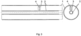
Figur 3 zeigt einen koaxialen Entladungsraum mit Ausbuchtung am Außenrohr. -
Figur 1 zeigt einen quaderförmigen Entladungsraum aus Quarzglas 1, bei dem auf zwei gegenüberliegenden Außenseiten Elektroden 2 angeordnet sind. Die Innenflächen der Umhüllung sind durch eine Ausbuchtung 3 miteinander verbunden, wobei in der Ausbuchtung ein metallischer Leiter 4 angeordnet ist. Grundsätzlich reicht eine Anordnung gemäßFigur 1 ,2 oder3 bei der eine Elektrode 2 mit einem in Richtung auf die Gegenelektrode 2 gerichteten elektrischen Leiter 4 den Abstand zwischen den Elektroden verkürzt. Besonders bewährt haben sich Anordnungen gemäßFiguren 1 bis 3 . Dort wird ein an einer Elektrode angeschlossener Leiter 4 innerhalb einer Ausbuchtung 3 in den Entladungsraum bis knapp an die gegenüberliegende Innenwand des Gasraumes geführt. Die Auswölbung kann mit der Gegenwand kontaktieren, so dass eine mechanische Stütze des Innenrohrs erzielt wird. Eine derartige Anordnung eignet sich für besonders lange Entladungsräume. - Zur Herstellung des erfindungsgemäßen Hochleistungsstrahlers wird eine Quarzglaskapillare 3 mit innenliegendem und auf einer Seite herausragendem Leiter 4 mit dem Quarzglaskörper 1 und einer Elektrode 2 verbunden. Dabei wird das Metall 4 an seiner offenen Seite elektrisch mit der Elektrode 2 verbunden und das Quarzglas der Kapillare dicht mit dem Lampenkörper 1 abgeschlossen. Mit dieser Maßnahme wird die Zündspannung auf ungefähr die Hälfte reduziert. Bei gängigen Lampen mit Zündspannung von 6 kV (Amplitude) wird nunmehr lediglich 3 kV (Amplitude) benötigt. Die Kapillarlänge ist in etwa gleich lang wie die Entladungsstrecke. Die Kapillare berührt dann die Gegenseite des Entladungsraums so, dass zwischen der Kapillare und der Gegenseite des Entladungsraumes noch Gas vorhanden ist, welches in Austausch mit dem Gas des gesamten Entladungsraumes steht.
- Gegenüber ohne äußere Isolierung in den Entladungsraum platzierten Leitern vereinfacht sich die Herstellung der erfindungsgemäßen Gasentladungsstrahler, da bei der Herstellung des Strahlers mit erfindungsgemäßer Zündhilfe die Anwendung von Schutzgas nicht mehr erforderlich ist. Weiterhin ergibt sich der Vorteil, dass im Betrieb die beeinträchtigende Verunreinigung durch Sputtern des im Entladungsraum platzierten Leiters unterbleibt.
- Für Gasentladungsstrahler mit koaxialer Anordnung befindet sich der Entladungsraum zwischen der Außenwand des Innenrohrs 1 und der Innenwand des Außenrohrs 1. Entsprechend wird die Ausbuchtung 3 zwischen der Außenwand des Innenrohrs 1 und der Innenwand des Außenrohrs 1 angeordnet.
- Ein erfindungsgemäß ausgeführter Koaxialstrahler mit einem Abstand von 10 mm zwischen dem Außen- und Innenrohr kann erfindungsgemäß mit einer Stromversorgung von 3 kV (Amplitude) gezündet werden.
Claims (5)
- Gasentladungsstrahler, insbesondere Hochleistungsstrahler, mit einem Entladungsraum (1) und zwei auf gegenüberliegenden Außenseiten des Entladungsraums angeordneten und Elektrodenflächen aufweisenden Elektroden (2), wobei die Umhüllung des Entladungsraums eine Ausbuchtung (3) aufweist, in der ein an eine Elektrodenfläche angeschlossener metallischer Leiter (4) in Richtung der Gegenelektrode verlegt ist,
dadurch gekennzeichnet, dass der metallische Leiter (4) innerhalb der Ausbuchtung (3) bis knapp an die gegenüberliegende Innenwand des Entladungsraums geführt ist. - Gasentladungsstrahler nach Anspruch 1, weiter dadurch gekennzeichnet, dass die Elektrodenflächen der gegenüberliegenden Elektroden 5 mm oder mehr, insbesondere 10 mm oder mehr, beabstandet sind.
- Gasentladungsstrahler nach Anspruch 1 oder 2, weiter dadurch gekennzeichnet, dass der Gasentladungsraum zwischen zwei koaxialen dielektrischen Rohren gebildet ist.
- Gasentladungsstrahler nach einem der Ansprüche 1 bis 3, weiter dadurch gekennzeichnet, dass die Ausbuchtung im Entladungsraum die gegenüberliegenden Innenwände des Entladungsraums miteinander verbindet.
- Verfahren zur Herstellung eines Gasentladungsstrahlers nach einem der vorhergehenden Ansprüche, wobei der metallische Leiter (4) über die Ausbuchtung (3) in den Entladungsraum (1) eingeführt wird und durch die Ausbuchtung vom Gasentladungsraum isoliert wird.
Applications Claiming Priority (1)
| Application Number | Priority Date | Filing Date | Title |
|---|---|---|---|
| DE102005062638A DE102005062638A1 (de) | 2005-12-23 | 2005-12-23 | Zündhilfe |
Publications (3)
| Publication Number | Publication Date |
|---|---|
| EP1811542A2 EP1811542A2 (de) | 2007-07-25 |
| EP1811542A3 EP1811542A3 (de) | 2007-08-08 |
| EP1811542B1 true EP1811542B1 (de) | 2017-03-15 |
Family
ID=38121594
Family Applications (1)
| Application Number | Title | Priority Date | Filing Date |
|---|---|---|---|
| EP06025792.0A Not-in-force EP1811542B1 (de) | 2005-12-23 | 2006-12-13 | Gasentladungsstrahler mit Aussenelektroden und einer Zündhilfe |
Country Status (7)
| Country | Link |
|---|---|
| EP (1) | EP1811542B1 (de) |
| KR (1) | KR20070066997A (de) |
| CN (1) | CN101067994A (de) |
| DE (1) | DE102005062638A1 (de) |
| DK (1) | DK1811542T3 (de) |
| SG (1) | SG133560A1 (de) |
| TW (1) | TW200805427A (de) |
Family Cites Families (10)
| Publication number | Priority date | Publication date | Assignee | Title |
|---|---|---|---|---|
| US2465414A (en) * | 1946-04-04 | 1949-03-29 | Harold W Abshire | Gaseous discharge device |
| JPH01243364A (ja) * | 1988-03-25 | 1989-09-28 | Matsushita Electric Works Ltd | 無電極放電灯装置 |
| DE4010809A1 (de) * | 1989-04-11 | 1990-10-18 | Asea Brown Boveri | Hochleistungsstrahler |
| DE4140497C2 (de) * | 1991-12-09 | 1996-05-02 | Heraeus Noblelight Gmbh | Hochleistungsstrahler |
| DE4222130C2 (de) * | 1992-07-06 | 1995-12-14 | Heraeus Noblelight Gmbh | Hochleistungsstrahler |
| DE10005156A1 (de) * | 2000-02-07 | 2001-08-09 | Patent Treuhand Ges Fuer Elektrische Gluehlampen Mbh | Flache Gasentladungslampe mit Abstandselementen |
| US20020030437A1 (en) * | 2000-09-13 | 2002-03-14 | Nobuhiro Shimizu | Light-emitting device and backlight for flat display |
| EP1328007A1 (de) * | 2001-12-14 | 2003-07-16 | Patent-Treuhand-Gesellschaft für elektrische Glühlampen mbH | Dielectric barrier discharge lamp with starting aid |
| JP2004227820A (ja) * | 2003-01-21 | 2004-08-12 | Iwasaki Electric Co Ltd | 放電ランプ |
| DE10312720A1 (de) * | 2003-03-21 | 2004-09-30 | Patent-Treuhand-Gesellschaft für elektrische Glühlampen mbH | Dielektrische Barriere-Entladungslampe mit Quetschdichtung |
-
2005
- 2005-12-23 DE DE102005062638A patent/DE102005062638A1/de not_active Ceased
-
2006
- 2006-12-13 DK DK06025792.0T patent/DK1811542T3/en active
- 2006-12-13 EP EP06025792.0A patent/EP1811542B1/de not_active Not-in-force
- 2006-12-21 SG SG200608908-0A patent/SG133560A1/en unknown
- 2006-12-22 TW TW095148649A patent/TW200805427A/zh unknown
- 2006-12-22 KR KR1020060133180A patent/KR20070066997A/ko not_active Ceased
- 2006-12-25 CN CNA2006101675936A patent/CN101067994A/zh active Pending
Also Published As
| Publication number | Publication date |
|---|---|
| KR20070066997A (ko) | 2007-06-27 |
| EP1811542A3 (de) | 2007-08-08 |
| DE102005062638A1 (de) | 2007-07-05 |
| CN101067994A (zh) | 2007-11-07 |
| SG133560A1 (en) | 2007-07-30 |
| EP1811542A2 (de) | 2007-07-25 |
| TW200805427A (en) | 2008-01-16 |
| DK1811542T3 (en) | 2017-06-12 |
Similar Documents
| Publication | Publication Date | Title |
|---|---|---|
| DE19718395C1 (de) | Leuchtstofflampe und Verfahren zu ihrem Betrieb | |
| DE102011054511B4 (de) | Glühkerze | |
| DE69903782T2 (de) | Einheit mit einer kurzbogen-entladungslampe mit anlaufantenne | |
| DE602004010629T2 (de) | Gasentladungslampe | |
| DE2333221A1 (de) | Magnetron | |
| EP0474065A1 (de) | Gasentladungsgefäss für Kompaktlampen | |
| EP1506567B1 (de) | Dielektrische barriere-entladungslampe mit sockel | |
| WO2007090762A1 (de) | Entladungslampe mit vergossenem sockel | |
| DE2733168C2 (de) | Hochdruck-Natriumdampflampe für Tonfrequenz-Impulsbetrieb | |
| DE19734863A1 (de) | Kompakte Fluoreszenzlampe mit verlängerten Schenkeln zur Schaffung eines kalten Fleckes | |
| DE10048986A1 (de) | Dielektrische Barrieren-Entladungslampe | |
| EP1811542A2 (de) | Gasentladungsstrahler mit Aussenelektroden und einer Zündhilfe | |
| DE10133326A1 (de) | Dielektrische Barrieren-Entladungslampe mit Zündhilfe | |
| DE69813693T2 (de) | Gesockelte elektrische lampe | |
| EP1659617B1 (de) | Leuchtmittel | |
| DE112010001171T5 (de) | Dielektrisch gefüllter Felderzeuger für EHID-Lampen und diesen umfassende EHID-Lampenanordnung | |
| DE10312720A1 (de) | Dielektrische Barriere-Entladungslampe mit Quetschdichtung | |
| DE102014103387A1 (de) | Verfahren zum Herstellen einer Koronazündeinrichtung | |
| WO2008113657A1 (de) | Dielektrische barriere-entladungslampe mit zündhilfe | |
| EP1646071B1 (de) | Beleuchtungssystem mit dielektrisch behinderter Entladungslampe und zugehörigem Vorschaltgerät | |
| DE3147705A1 (de) | Starthilfe fuer nicht-geradlinige entladungslampen und verfahren zur herstellung derselben | |
| WO2010025770A1 (de) | Entladungslampe | |
| DE102004047374A1 (de) | Dielektrisch behinderte Entladungslampe mit elektrischer Abschirmung | |
| WO2009052851A1 (de) | Einbaulampe mit kabel, insbesondere zur flugplatzbefeuerung | |
| DE102023133105B4 (de) | Hochfrequenzplasmalichtquelle |
Legal Events
| Date | Code | Title | Description |
|---|---|---|---|
| PUAI | Public reference made under article 153(3) epc to a published international application that has entered the european phase |
Free format text: ORIGINAL CODE: 0009012 |
|
| PUAL | Search report despatched |
Free format text: ORIGINAL CODE: 0009013 |
|
| 17P | Request for examination filed |
Effective date: 20070112 |
|
| AK | Designated contracting states |
Kind code of ref document: A2 Designated state(s): AT BE BG CH CY CZ DE DK EE ES FI FR GB GR HU IE IS IT LI LT LU LV MC NL PL PT RO SE SI SK TR |
|
| AX | Request for extension of the european patent |
Extension state: AL BA HR MK YU |
|
| AK | Designated contracting states |
Kind code of ref document: A3 Designated state(s): AT BE BG CH CY CZ DE DK EE ES FI FR GB GR HU IE IS IT LI LT LU LV MC NL PL PT RO SE SI SK TR |
|
| AX | Request for extension of the european patent |
Extension state: AL BA HR MK YU |
|
| 17Q | First examination report despatched |
Effective date: 20080206 |
|
| AKX | Designation fees paid |
Designated state(s): AT BE BG CH CY CZ DE DK EE ES FI FR GB GR HU IE IS IT LI LT LU LV MC NL PL PT RO SE SI SK TR |
|
| GRAP | Despatch of communication of intention to grant a patent |
Free format text: ORIGINAL CODE: EPIDOSNIGR1 |
|
| INTG | Intention to grant announced |
Effective date: 20160701 |
|
| RIN1 | Information on inventor provided before grant (corrected) |
Inventor name: VORONOV, ALEXEI Inventor name: REBER, SILKE Inventor name: SCHILLING, FRANZ |
|
| STAA | Information on the status of an ep patent application or granted ep patent |
Free format text: STATUS: GRANT OF PATENT IS INTENDED |
|
| GRAS | Grant fee paid |
Free format text: ORIGINAL CODE: EPIDOSNIGR3 |
|
| GRAA | (expected) grant |
Free format text: ORIGINAL CODE: 0009210 |
|
| STAA | Information on the status of an ep patent application or granted ep patent |
Free format text: STATUS: THE PATENT HAS BEEN GRANTED |
|
| AK | Designated contracting states |
Kind code of ref document: B1 Designated state(s): AT BE BG CH CY CZ DE DK EE ES FI FR GB GR HU IE IS IT LI LT LU LV MC NL PL PT RO SE SI SK TR |
|
| REG | Reference to a national code |
Ref country code: GB Ref legal event code: FG4D Free format text: NOT ENGLISH Ref country code: CH Ref legal event code: EP |
|
| REG | Reference to a national code |
Ref country code: IE Ref legal event code: FG4D Free format text: LANGUAGE OF EP DOCUMENT: GERMAN |
|
| REG | Reference to a national code |
Ref country code: AT Ref legal event code: REF Ref document number: 876349 Country of ref document: AT Kind code of ref document: T Effective date: 20170415 |
|
| REG | Reference to a national code |
Ref country code: DE Ref legal event code: R096 Ref document number: 502006015411 Country of ref document: DE |
|
| REG | Reference to a national code |
Ref country code: NL Ref legal event code: FP |
|
| REG | Reference to a national code |
Ref country code: DK Ref legal event code: T3 Effective date: 20170606 |
|
| REG | Reference to a national code |
Ref country code: LT Ref legal event code: MG4D |
|
| PG25 | Lapsed in a contracting state [announced via postgrant information from national office to epo] |
Ref country code: LT Free format text: LAPSE BECAUSE OF FAILURE TO SUBMIT A TRANSLATION OF THE DESCRIPTION OR TO PAY THE FEE WITHIN THE PRESCRIBED TIME-LIMIT Effective date: 20170315 Ref country code: FI Free format text: LAPSE BECAUSE OF FAILURE TO SUBMIT A TRANSLATION OF THE DESCRIPTION OR TO PAY THE FEE WITHIN THE PRESCRIBED TIME-LIMIT Effective date: 20170315 Ref country code: GR Free format text: LAPSE BECAUSE OF FAILURE TO SUBMIT A TRANSLATION OF THE DESCRIPTION OR TO PAY THE FEE WITHIN THE PRESCRIBED TIME-LIMIT Effective date: 20170616 |
|
| PG25 | Lapsed in a contracting state [announced via postgrant information from national office to epo] |
Ref country code: LV Free format text: LAPSE BECAUSE OF FAILURE TO SUBMIT A TRANSLATION OF THE DESCRIPTION OR TO PAY THE FEE WITHIN THE PRESCRIBED TIME-LIMIT Effective date: 20170315 Ref country code: SE Free format text: LAPSE BECAUSE OF FAILURE TO SUBMIT A TRANSLATION OF THE DESCRIPTION OR TO PAY THE FEE WITHIN THE PRESCRIBED TIME-LIMIT Effective date: 20170315 Ref country code: BG Free format text: LAPSE BECAUSE OF FAILURE TO SUBMIT A TRANSLATION OF THE DESCRIPTION OR TO PAY THE FEE WITHIN THE PRESCRIBED TIME-LIMIT Effective date: 20170615 |
|
| PG25 | Lapsed in a contracting state [announced via postgrant information from national office to epo] |
Ref country code: ES Free format text: LAPSE BECAUSE OF FAILURE TO SUBMIT A TRANSLATION OF THE DESCRIPTION OR TO PAY THE FEE WITHIN THE PRESCRIBED TIME-LIMIT Effective date: 20170315 Ref country code: CZ Free format text: LAPSE BECAUSE OF FAILURE TO SUBMIT A TRANSLATION OF THE DESCRIPTION OR TO PAY THE FEE WITHIN THE PRESCRIBED TIME-LIMIT Effective date: 20170315 Ref country code: SK Free format text: LAPSE BECAUSE OF FAILURE TO SUBMIT A TRANSLATION OF THE DESCRIPTION OR TO PAY THE FEE WITHIN THE PRESCRIBED TIME-LIMIT Effective date: 20170315 Ref country code: RO Free format text: LAPSE BECAUSE OF FAILURE TO SUBMIT A TRANSLATION OF THE DESCRIPTION OR TO PAY THE FEE WITHIN THE PRESCRIBED TIME-LIMIT Effective date: 20170315 Ref country code: EE Free format text: LAPSE BECAUSE OF FAILURE TO SUBMIT A TRANSLATION OF THE DESCRIPTION OR TO PAY THE FEE WITHIN THE PRESCRIBED TIME-LIMIT Effective date: 20170315 Ref country code: IT Free format text: LAPSE BECAUSE OF FAILURE TO SUBMIT A TRANSLATION OF THE DESCRIPTION OR TO PAY THE FEE WITHIN THE PRESCRIBED TIME-LIMIT Effective date: 20170315 |
|
| PG25 | Lapsed in a contracting state [announced via postgrant information from national office to epo] |
Ref country code: IS Free format text: LAPSE BECAUSE OF FAILURE TO SUBMIT A TRANSLATION OF THE DESCRIPTION OR TO PAY THE FEE WITHIN THE PRESCRIBED TIME-LIMIT Effective date: 20170715 Ref country code: PL Free format text: LAPSE BECAUSE OF FAILURE TO SUBMIT A TRANSLATION OF THE DESCRIPTION OR TO PAY THE FEE WITHIN THE PRESCRIBED TIME-LIMIT Effective date: 20170315 |
|
| REG | Reference to a national code |
Ref country code: DE Ref legal event code: R082 Ref document number: 502006015411 Country of ref document: DE Representative=s name: KLEINEVOSS, ULF, DIPL.-PHYS. DR. RER. NAT., DE Ref country code: DE Ref legal event code: R082 Ref document number: 502006015411 Country of ref document: DE Representative=s name: KLEINEVOSS, ULF, DIPL.-PHYS. DR.RER.NAT., DE |
|
| REG | Reference to a national code |
Ref country code: DE Ref legal event code: R097 Ref document number: 502006015411 Country of ref document: DE |
|
| REG | Reference to a national code |
Ref country code: FR Ref legal event code: PLFP Year of fee payment: 12 |
|
| PLBE | No opposition filed within time limit |
Free format text: ORIGINAL CODE: 0009261 |
|
| STAA | Information on the status of an ep patent application or granted ep patent |
Free format text: STATUS: NO OPPOSITION FILED WITHIN TIME LIMIT |
|
| 26N | No opposition filed |
Effective date: 20171218 |
|
| PG25 | Lapsed in a contracting state [announced via postgrant information from national office to epo] |
Ref country code: SI Free format text: LAPSE BECAUSE OF FAILURE TO SUBMIT A TRANSLATION OF THE DESCRIPTION OR TO PAY THE FEE WITHIN THE PRESCRIBED TIME-LIMIT Effective date: 20170315 |
|
| REG | Reference to a national code |
Ref country code: IE Ref legal event code: MM4A |
|
| PG25 | Lapsed in a contracting state [announced via postgrant information from national office to epo] |
Ref country code: LU Free format text: LAPSE BECAUSE OF NON-PAYMENT OF DUE FEES Effective date: 20171213 |
|
| PG25 | Lapsed in a contracting state [announced via postgrant information from national office to epo] |
Ref country code: IE Free format text: LAPSE BECAUSE OF NON-PAYMENT OF DUE FEES Effective date: 20171213 |
|
| REG | Reference to a national code |
Ref country code: AT Ref legal event code: MM01 Ref document number: 876349 Country of ref document: AT Kind code of ref document: T Effective date: 20171213 |
|
| PG25 | Lapsed in a contracting state [announced via postgrant information from national office to epo] |
Ref country code: AT Free format text: LAPSE BECAUSE OF NON-PAYMENT OF DUE FEES Effective date: 20171213 |
|
| PG25 | Lapsed in a contracting state [announced via postgrant information from national office to epo] |
Ref country code: MC Free format text: LAPSE BECAUSE OF FAILURE TO SUBMIT A TRANSLATION OF THE DESCRIPTION OR TO PAY THE FEE WITHIN THE PRESCRIBED TIME-LIMIT Effective date: 20170315 Ref country code: HU Free format text: LAPSE BECAUSE OF FAILURE TO SUBMIT A TRANSLATION OF THE DESCRIPTION OR TO PAY THE FEE WITHIN THE PRESCRIBED TIME-LIMIT; INVALID AB INITIO Effective date: 20061213 |
|
| PG25 | Lapsed in a contracting state [announced via postgrant information from national office to epo] |
Ref country code: CY Free format text: LAPSE BECAUSE OF NON-PAYMENT OF DUE FEES Effective date: 20170315 |
|
| PGFP | Annual fee paid to national office [announced via postgrant information from national office to epo] |
Ref country code: NL Payment date: 20191219 Year of fee payment: 14 |
|
| PGFP | Annual fee paid to national office [announced via postgrant information from national office to epo] |
Ref country code: FR Payment date: 20191219 Year of fee payment: 14 Ref country code: DK Payment date: 20191227 Year of fee payment: 14 Ref country code: BE Payment date: 20191219 Year of fee payment: 14 |
|
| PG25 | Lapsed in a contracting state [announced via postgrant information from national office to epo] |
Ref country code: TR Free format text: LAPSE BECAUSE OF FAILURE TO SUBMIT A TRANSLATION OF THE DESCRIPTION OR TO PAY THE FEE WITHIN THE PRESCRIBED TIME-LIMIT Effective date: 20170315 |
|
| PGFP | Annual fee paid to national office [announced via postgrant information from national office to epo] |
Ref country code: CH Payment date: 20191219 Year of fee payment: 14 |
|
| PGFP | Annual fee paid to national office [announced via postgrant information from national office to epo] |
Ref country code: GB Payment date: 20191220 Year of fee payment: 14 |
|
| PG25 | Lapsed in a contracting state [announced via postgrant information from national office to epo] |
Ref country code: PT Free format text: LAPSE BECAUSE OF FAILURE TO SUBMIT A TRANSLATION OF THE DESCRIPTION OR TO PAY THE FEE WITHIN THE PRESCRIBED TIME-LIMIT Effective date: 20170315 |
|
| REG | Reference to a national code |
Ref country code: DK Ref legal event code: EBP Effective date: 20201231 |
|
| REG | Reference to a national code |
Ref country code: CH Ref legal event code: PL |
|
| REG | Reference to a national code |
Ref country code: NL Ref legal event code: MM Effective date: 20210101 |
|
| GBPC | Gb: european patent ceased through non-payment of renewal fee |
Effective date: 20201213 |
|
| REG | Reference to a national code |
Ref country code: BE Ref legal event code: MM Effective date: 20201231 |
|
| PG25 | Lapsed in a contracting state [announced via postgrant information from national office to epo] |
Ref country code: NL Free format text: LAPSE BECAUSE OF NON-PAYMENT OF DUE FEES Effective date: 20210101 |
|
| PG25 | Lapsed in a contracting state [announced via postgrant information from national office to epo] |
Ref country code: FR Free format text: LAPSE BECAUSE OF NON-PAYMENT OF DUE FEES Effective date: 20201231 |
|
| PG25 | Lapsed in a contracting state [announced via postgrant information from national office to epo] |
Ref country code: LI Free format text: LAPSE BECAUSE OF NON-PAYMENT OF DUE FEES Effective date: 20201231 Ref country code: GB Free format text: LAPSE BECAUSE OF NON-PAYMENT OF DUE FEES Effective date: 20201213 Ref country code: CH Free format text: LAPSE BECAUSE OF NON-PAYMENT OF DUE FEES Effective date: 20201231 |
|
| PG25 | Lapsed in a contracting state [announced via postgrant information from national office to epo] |
Ref country code: DK Free format text: LAPSE BECAUSE OF NON-PAYMENT OF DUE FEES Effective date: 20201231 |
|
| PGFP | Annual fee paid to national office [announced via postgrant information from national office to epo] |
Ref country code: DE Payment date: 20211210 Year of fee payment: 16 |
|
| PG25 | Lapsed in a contracting state [announced via postgrant information from national office to epo] |
Ref country code: BE Free format text: LAPSE BECAUSE OF NON-PAYMENT OF DUE FEES Effective date: 20201231 |
|
| REG | Reference to a national code |
Ref country code: DE Ref legal event code: R119 Ref document number: 502006015411 Country of ref document: DE |
|
| P01 | Opt-out of the competence of the unified patent court (upc) registered |
Effective date: 20230526 |
|
| PG25 | Lapsed in a contracting state [announced via postgrant information from national office to epo] |
Ref country code: DE Free format text: LAPSE BECAUSE OF NON-PAYMENT OF DUE FEES Effective date: 20230701 |