EP1811279B1 - Device for locking-unlocking tired wheels of vehicles on a mandrel of a maintenance machine - Google Patents
Device for locking-unlocking tired wheels of vehicles on a mandrel of a maintenance machine Download PDFInfo
- Publication number
- EP1811279B1 EP1811279B1 EP07000753A EP07000753A EP1811279B1 EP 1811279 B1 EP1811279 B1 EP 1811279B1 EP 07000753 A EP07000753 A EP 07000753A EP 07000753 A EP07000753 A EP 07000753A EP 1811279 B1 EP1811279 B1 EP 1811279B1
- Authority
- EP
- European Patent Office
- Prior art keywords
- valve
- bell
- work chamber
- piston
- shaped member
- Prior art date
- Legal status (The legal status is an assumption and is not a legal conclusion. Google has not performed a legal analysis and makes no representation as to the accuracy of the status listed.)
- Active
Links
- 238000012423 maintenance Methods 0.000 title claims abstract description 10
- 239000012530 fluid Substances 0.000 claims abstract description 38
- 238000007599 discharging Methods 0.000 claims abstract description 4
- 238000004891 communication Methods 0.000 claims description 20
- 230000033001 locomotion Effects 0.000 description 5
- 230000002093 peripheral effect Effects 0.000 description 3
- 238000000926 separation method Methods 0.000 description 3
- 240000008100 Brassica rapa Species 0.000 description 1
- 238000013459 approach Methods 0.000 description 1
- 230000005540 biological transmission Effects 0.000 description 1
- 238000006243 chemical reaction Methods 0.000 description 1
- 230000002860 competitive effect Effects 0.000 description 1
- 238000006073 displacement reaction Methods 0.000 description 1
- 239000007788 liquid Substances 0.000 description 1
- 238000004519 manufacturing process Methods 0.000 description 1
- 238000012986 modification Methods 0.000 description 1
- 230000004048 modification Effects 0.000 description 1
- 230000010355 oscillation Effects 0.000 description 1
- 230000002441 reversible effect Effects 0.000 description 1
Images


Classifications
-
- G—PHYSICS
- G01—MEASURING; TESTING
- G01M—TESTING STATIC OR DYNAMIC BALANCE OF MACHINES OR STRUCTURES; TESTING OF STRUCTURES OR APPARATUS, NOT OTHERWISE PROVIDED FOR
- G01M1/00—Testing static or dynamic balance of machines or structures
- G01M1/02—Details of balancing machines or devices
- G01M1/04—Adaptation of bearing support assemblies for receiving the body to be tested
- G01M1/045—Adaptation of bearing support assemblies for receiving the body to be tested the body being a vehicle wheel
-
- B—PERFORMING OPERATIONS; TRANSPORTING
- B23—MACHINE TOOLS; METAL-WORKING NOT OTHERWISE PROVIDED FOR
- B23B—TURNING; BORING
- B23B31/00—Chucks; Expansion mandrels; Adaptations thereof for remote control
- B23B31/40—Expansion mandrels
- B23B31/42—Expansion mandrels characterised by features relating primarily to remote control of the gripping means
Definitions
- the present invention regards a device for locking-unlocking a body rotating on a rotating mandrel of an operating machine, particularly adapted for locking-unlocking tired wheels of vehicles on the rotating mandrel of a tired wheel maintenance machine, such as a balancing machine or a tire assembly-disassembly machine.
- US-5 777 224 relates to a rotatable drive spindle for balancing wheel vehicles, which includes, among other things, a hollow shaft and a control rod passing through the hollow shaft and displaceable between a locking position and an unlocking position.
- the spindle further comprises a spring and a pneumatic jack designed to cause displacement of the control rod from the locking to the unlocking position against the action of the spring.
- the main object of the present invention is that of providing a device for locking-unlocking a tired wheel of a vehicle on a rotating mandrel, where any driving connection between actual locking-unlocking device and mandrel intended to rotate is absent.
- Another object of the present invention is that of making available a locking-unlocking device substantially free of rotating floating masses.
- Another object of the present invention is that of providing a compact locking-unlocking device of limited size and which can be produced at highly competitive manufacturing costs.
- a locking device for a maintenance machine of a rotating body, having a hollow fixed support element borne by the maintenance machine, a bell-shaped flanged member mounted for rotation coaxially to said hollow support element and designed to support said rotating body, holding means suitable for removably fixing said rotating body against said flange of said bell-shaped member, driving means suitable for driving said bell-shaped member into rotation upon control, and a control system, characterized in that it comprises a sleeve element operatively connected with said driving means and mounted for rotation on said fixed support element, and having one end thereof extending overhanging beyond said fixed support and coaxially supporting the bell-shaped member at the head thereof, thereby delimiting a work chamber with the bell-shaped member; a piston element mounted slidably mounted in said work chamber; an axial piston rod member slidably mounted in an axial shank portion of said bell-shaped member and having an inner end thereof fixed to said piston element and its other end overhangingly extending in axial
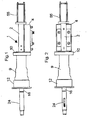
- a locking-unlocking device generically indicated with 1, according to the present invention is composed of a hollow fixed support element or cylindrical shaft 2 having an inner axial cavity 3 and designed to be supported by a fixed structure 4 of a maintenance machine of tired wheels, typically a balancing machine (not shown in the drawings) of any suitable type.
- a tired wheel is schematically illustrated by a central section 5 of its rim in Figs. 7 to 11 .
- the cylindrical shaft 2 has two outer diameters : a greater 2a and a smaller 2b, and thus in an intermediate zone thereof a peripheral shoulder 6 is delimited.
- an outer receiving seat is formed for one or more bearings 7.
- a bearing 8 is inserted designed to abut against the shoulder 6, as well as a sleeve 9, which is supported ovethangingly projecting from the shaft 2 and rotating with respect thereto, since at one end thereof equipped with flange 10 it is supported on the bearing 8, while at an internal intermediate portion thereof it is borne by the bearing or bearings 7.
- the sleeve 9 is operatively connectable, e. g. by means of a motion transmission belt to driving or motion source means, such as an electric motor of any suitable type (not shown in the drawings).
- the sleeve 9 supports, coaxially fixed to it, e. g. by means of bolts 11, a bell-shaped member 12, which has an abutment end flange 13 for a tired wheel rim 5 to be balanced and internally delimits a peripheral annular chamber 14, on whose bottom the fixing bolts 11 ate screwed, and an axial through opening 15 within a shank portion 16, it too axial.
- the sleeve 9 and bell-shaped member 12 together constitute a rotatable hollow mandrel, typically for a balancing machine.
- a work chamber 17 is delimited, preferably equipped with lining jacket 18, within which a piston element 19 is arranged sliding, preferably equipped with sliding peripheral seal 20 to ensure the seal with the inner wall of the chamber 17 or its lining 18.
- the piston 19 is equipped with an axial piston rod member 21 which extends in the axial through opening 15 of the bell-shaped member 12.
- the piston rod 21 is constructively supported on a sliding support means, such as a bush 16a, placed in the through opening 15 and is connected, for example screwed, to an extension rod 22 in turn rigidly connected or integral with a slide guide element 23 slidable within a containment cylinder 24 connected, e. g. screwed, to the hollow shank 16, to form an extension at the hub of the shank 16 of the bell-shaped member 12.
- a sliding support means such as a bush 16a
- an extension rod 22 in turn rigidly connected or integral with a slide guide element 23 slidable within a containment cylinder 24 connected, e. g. screwed, to the hollow shank 16, to form an extension at the hub of the shank 16 of the bell-shaped member 12.
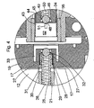
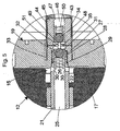
- the piston rod 21, at its piston 19 attachment end, has a blind terminal axial cavity 25 in which a resilient loading means is housed, e. g. a calibrated helical spring 26. More particularly, the piston rod 21 has its externally threaded end 27, which can be screwed into an internally-threaded axial receiving seat 28 with the interposition of a seal 29. Very close to the piston 19, but located outside it, the piston rod 21 at the cavity or light 25 has one or a number of lateral passages or ports 30 which place the cavity 25 in fluid communication with the chamber 17 ( Fig. 5 ).
- the receiving seat 28 also delimits an annular valve seat 31, preferably with one or more frustoconical surfaces for the engagement by a valve means or element, typically a sphere 32, resiliently loaded by the spring 26 and movable between a closed or interception position, as shown in Fig. 4 , and open positions ( Fig. 5 ) to allow a work fluid to flow through it, i.e. to allow the work fluid to cross the piston 19, as will be explained in more detail below.
- an annular recess 33 is formed acting as receiving seat, as will be explained below.
- a tubular element or rigid tube 34 is mounted which is supported by two rings or seals 41 and 42 and delimits a fluid sealed gap 37 with the cylindrical shaft 2 which is in communication with the outside of the cylindrical shaft 2 through a through opening or pair of through openings 38 formed in the wall of the shaft 2 and with the interior of the tube 34 through a passage or hole 40.
- the seal of the air space 37 is ensured by a pair of terminal seals 41 and 42.
- the tube 34 is in fluid communication with the chamber itself and has an inner enlargement 43 in its cavity, in which a hollow valve body 45 is housed and fixed, e.g. by means of screwing in at 44, a hollow body 45 preferably having a wider inner axial opening 46 than the inner opening of the tube 34, such that a shoulder is delimited at one end thereof abutting against the bottom of the enlargement 43.
- the valve body has an inner narrowing which delimits a valve seat 47, against which a valve element 49 resiliendy loaded by resilient loading means, preferably a calibrated helical spring 50 acting from the opposite side, e. g.
- valve element 48 is thus movable between a rest or closed position in which it is pushed by the spring 50 against its valve seat 49 and a work or open position in which it is moved away from its valve seat, as will be further explained below.
- the valve element 48 supports or is integral with a tappet means or element 51, preferably maintained axially guided (in any suitable manner) within a valve body 45 so as exiling from the valve body 45 and overhangingly to extend therefrom.
- the valve body 45 is embedded in the tube 34 so that to leave clear a terminal opening section 52 of the tube 34 with length substantially equal to the depth of the annular recess 33 formed in the piston 19, whereby the terminal section 52 of the tube 34 can removably penetrate within the annular recess 33.
- a sealed chamber 35 is delimited between piston 19 and rigid tube 34 (and with the front of the valve body 45), through which, when the valve element 48 opens, or rather moves the valve element 32 backward by means of the tappet element 51, communication occurs between inner opening 46 of the tube 34 and work chamber 17.
- the chamber 35 which meanwhile increases its capacity owing to separation of the valve body 45 from the piston 19, remains at the same pressure as that present in the work chamber 17 until the valve element 32 is brought into closed position, This ensures that after the loading of the work chamber 17 with pressurized (air) fluid, the chamber 17 does not experience an abrupt drop of pressure in the closing step of the valve element 32, a phenomenon which would occur if the seal chamber 35 was not foreseen.
- the tube 34 is blind and extends outwardly from the shaft 2 in order to be engaged in any suitable manner with a linear actuator means, preferably formed by a piston or displacer element 53 rigid in movement with the tube 34 so that to cause it axially to slide, upon control, within the shaft 2.
- the displacer 53 is mounted sealedly sliding within the chamber 54 of a cylinder 55, e. g. overhangingly supported by a fixed collar 56 fixed on the shaft 2.
- Pressurized work fluid e. g. pressurized air, can be supplied to the chamber 54 through input/output openings formed on the side opposite to the displacer 53, as will be explained below.
- the cylinder 55 and the displacer 53 form a double-acting fluid-operated piston and cylinder group or unit.
- the input/output openings for the chamber 54 are indicated with 57 and 58 and are in communication with a fluid (air or liquid)-operated control system, generically indicated with 59, which comprises a pressurized fluid source, such as a compressor or a pump, of any suitable type and generically indicated with 60 in the drawings, valve means, e. g. composed of an electric distribution valve 61 in fluid communication with the source of pressurized work fluid 60 and having two outputs 62 and 63.
- the outlet 62 is connected with both the input/output 38 in the shaft 2 and with a valve group 64 in turn connected with the input/output 57 to the chamber 54.
- the valve group 64 is formed by a throttling member and by a check valve connected in parallel the check valve being arranged to intercept the flow directed to the chamber 54.
- the output 63 is instead connected with a valve group 65 in turn connected with the input/ouzput 58 to the chamber 54,
- the valve group 65 is formed by a throttling member and a check valve connected in parallel, with the check valve being designed to intercept the return flow from the chamber 54.
- the electric valve 61 can be controlled by two control pedals 66 and 67 operable by the operator of the balancing machine, as shall be explained below.
- the pressurized air which thus enters into the chamber 54 from the displacer side 53 opposite that of the tube or piston rod 34, moves the displacer 53 in the direction to make the sliding tube 34 advance within the shaft 2 until it inserts, firstly, its other internally enlarged end 43 in the recess 33 of the piston 19 so to bring the two valve seats 49 and 31 into reciprocal abutment, and thus to bring the tappet element 51 against the valve element 32, which is forced to move backward against the force of the spring 26 and at the same time, by reaction, move the valve element 48 backward, which supports the tappet element 51 ( Figs. 5 and 7 ),
- the communication is opened between the inner opening of the tube 34, the axial opening 46 of the valve formed by the valve body 45 and by the valve element 48, the axial opening 25 of the piston rod 21 through the valve element 32, the lateral opening or openings 30, the opening 15 and the chamber 17, which can thus be supplied with pressurized air.
- the operator places a wheel 5 to be balanced onto the hub 24 and locks it in position against the bell-shaped member 12 by means of any suitable removable holding or fixing means, e. g. a ring 68 with external conical surface for centering the wheel rim 5 on the rotation axis of the mandrel and internally threaded for its screwing on the hub 24.
- any suitable removable holding or fixing means e. g. a ring 68 with external conical surface for centering the wheel rim 5 on the rotation axis of the mandrel and internally threaded for its screwing on the hub 24.
- the air supplied to the input/output 38 reaches the air space 37 between piston rod 2 and tube 34 and thus enters the inner opening of the tube 34 through the hole or holes 40, thereby placing the chamber 17 under pressure, At the same time, the air supplied through the input/output 57 pressurizes the chamber 54 on the side of the displacer 53 turned towards the tube 34 (pressurizing step of the locking/unlocking device).
- the operator drives the pedal 67 to activate the electric valve 61, which opens the inputs/outputs 38 and 57, discharging them, while it begins supplying compressed air to the input/output 58 through the valve group ( Fig. 10 ).
- the displacer 53 is pushed to make the tube 34 advance towards the piston 19 until it moves the valve elements 32 and 48 into open position, thus discharging the chamber 17 of the pressurized air therein contained, which then follows a backwards path through the openings 30, the opening or light 25 of the piston rod 21, the inner light or opening of the tube 34, the openings 40, the air space 37 and the input/output valve 38 now discharged ( Fig. 10 ).
- a device is formed by a movable part composed of the sleeve 9, bell-shaped member 12, piston 19, piston rod 21 and by the containment cylinder 24 designed to rotate at relatively high speed in the step of balancing a tired wheel 5, and by a fixed part comprising the cylindrical shaft 2, the rigid tubular element 34 and the linear actuator, formed by the cylinder 54 and the displacer 53, and designed to move closer to the movable part in order to supply pressurized (air) fluid to the work chamber (17) and to move away from it to remain stopped (non-rotating) during the rotation of the movable part
- the work chamber 17 is discharged in any suitable manner and the piston 19 is caused to return to its initial position, that at which the locking means 68 are removed from the flange 13, e.g.
- the fixed part once again approaches the movable part to carry out both the discharge of the work chamber 17 and the backward movement of the piston 19 through the operation of the linear operator 53, 55.
- the fluid-operated control system 59 can comprise an electric-electronic portion arranged to drive a linear actuator, such as a rack, driven by a reversible electric motor designed to make the rigid tube 34 move.
Landscapes
- Physics & Mathematics (AREA)
- General Physics & Mathematics (AREA)
- Engineering & Computer Science (AREA)
- Mechanical Engineering (AREA)
- Testing Of Balance (AREA)
- Compressors, Vaccum Pumps And Other Relevant Systems (AREA)
- Vehicle Cleaning, Maintenance, Repair, Refitting, And Outriggers (AREA)
- Lock And Its Accessories (AREA)
- Fluid-Damping Devices (AREA)
Applications Claiming Priority (1)
| Application Number | Priority Date | Filing Date | Title |
|---|---|---|---|
| IT000013A ITVR20060013A1 (it) | 2006-01-19 | 2006-01-19 | Dispositivo per bloccare-sbloccare ruote gommate di veicoli su un mandrino di una macchina di manutenzione. |
Publications (3)
| Publication Number | Publication Date |
|---|---|
| EP1811279A2 EP1811279A2 (en) | 2007-07-25 |
| EP1811279A3 EP1811279A3 (en) | 2009-10-07 |
| EP1811279B1 true EP1811279B1 (en) | 2012-03-07 |
Family
ID=37950597
Family Applications (1)
| Application Number | Title | Priority Date | Filing Date |
|---|---|---|---|
| EP07000753A Active EP1811279B1 (en) | 2006-01-19 | 2007-01-16 | Device for locking-unlocking tired wheels of vehicles on a mandrel of a maintenance machine |
Country Status (6)
| Country | Link |
|---|---|
| US (1) | US7900511B2 (it) |
| EP (1) | EP1811279B1 (it) |
| JP (1) | JP4819704B2 (it) |
| CN (1) | CN100584648C (it) |
| AT (1) | ATE548640T1 (it) |
| IT (1) | ITVR20060013A1 (it) |
Cited By (1)
| Publication number | Priority date | Publication date | Assignee | Title |
|---|---|---|---|---|
| EP3096122A1 (en) | 2015-05-20 | 2016-11-23 | CORGHI S.p.A. | Balancing machine |
Families Citing this family (5)
| Publication number | Priority date | Publication date | Assignee | Title |
|---|---|---|---|---|
| CN101424578B (zh) * | 2007-11-02 | 2011-10-19 | 焦建飞 | 轮胎拆装、平衡一体机 |
| CN101474948B (zh) * | 2008-01-03 | 2013-09-11 | 焦建飞 | 拆胎平衡一体机 |
| ITVR20080018A1 (it) * | 2008-02-13 | 2009-08-14 | Butler Engineering & Marketing Spa | Dispositivo di movimentazione di un carico resistente, in particolare uno o piu' bracci di lavoro |
| ES2620974T3 (es) * | 2015-03-12 | 2017-06-30 | Corghi S.P.A. | Máquina de servicio de ruedas y método para bloquear una rueda a una unidad de soporte de ruedas |
| CN107234562B (zh) * | 2017-06-28 | 2018-03-16 | 亚洲硅业(青海)有限公司 | 一种硅芯固定装置 |
Family Cites Families (7)
| Publication number | Priority date | Publication date | Assignee | Title |
|---|---|---|---|---|
| IT1072196B (it) * | 1977-03-29 | 1985-04-10 | Italiana Costruzioni Elettrome | Dispositivo per il bloccaggio automatico delle ruote degli autoveicoli sulle macchine equilibratrici in genere |
| DE4200365A1 (de) * | 1992-01-09 | 1993-07-15 | Mengeringhausen Nachf Gmbh & C | Vorrichtung zur automatischen zentralbefestigung von rotationsteilen |
| FR2739688B1 (fr) | 1995-10-04 | 1997-11-28 | Muller Bem | Broche d'entrainement en rotation a montage rapide, et machine comportant une telle broche |
| IT1287823B1 (it) * | 1996-09-06 | 1998-08-19 | Femas Srl | Dispositivo automatico di bloccaggio delle ruote di automezzi in genere sugli alberi delle macchine equilibratrici |
| DE10238271B4 (de) * | 2002-08-21 | 2012-11-08 | Snap-On Equipment Gmbh | Verfahren und Vorrichtung zum zentrierten Spannen eines Kraftfahrzeugrades auf eine Hauptwelle einer Radauswuchtmaschine |
| ITRE20020074A1 (it) * | 2002-10-02 | 2004-04-03 | Corghi Spa | Gruppo di bloccaggio e trascinamento di un corpo rotante, |
| US6668859B1 (en) * | 2002-10-21 | 2003-12-30 | Hsuan-Lung Wu | Hydraulic collet assembly with a valve unit |
-
2006
- 2006-01-19 IT IT000013A patent/ITVR20060013A1/it unknown
-
2007
- 2007-01-16 EP EP07000753A patent/EP1811279B1/en active Active
- 2007-01-16 AT AT07000753T patent/ATE548640T1/de active
- 2007-01-17 JP JP2007008396A patent/JP4819704B2/ja active Active
- 2007-01-19 US US11/655,184 patent/US7900511B2/en active Active
- 2007-01-19 CN CN200710000774A patent/CN100584648C/zh active Active
Cited By (2)
| Publication number | Priority date | Publication date | Assignee | Title |
|---|---|---|---|---|
| EP3096122A1 (en) | 2015-05-20 | 2016-11-23 | CORGHI S.p.A. | Balancing machine |
| US10006830B2 (en) | 2015-05-20 | 2018-06-26 | Nexion S.P.A. | Balancing machine |
Also Published As
| Publication number | Publication date |
|---|---|
| ATE548640T1 (de) | 2012-03-15 |
| US7900511B2 (en) | 2011-03-08 |
| EP1811279A2 (en) | 2007-07-25 |
| JP4819704B2 (ja) | 2011-11-24 |
| JP2007212451A (ja) | 2007-08-23 |
| CN100584648C (zh) | 2010-01-27 |
| EP1811279A3 (en) | 2009-10-07 |
| ITVR20060013A1 (it) | 2007-07-20 |
| CN101003248A (zh) | 2007-07-25 |
| US20070180906A1 (en) | 2007-08-09 |
Similar Documents
| Publication | Publication Date | Title |
|---|---|---|
| EP1811279B1 (en) | Device for locking-unlocking tired wheels of vehicles on a mandrel of a maintenance machine | |
| US4068559A (en) | Tool fastening device | |
| TWI382890B (zh) | 驅動作動單元之方法及執行該方法之裝置 | |
| CN108454316B (zh) | 用于支撑和紧固轮胎车轮的轮辋的组件 | |
| US5096347A (en) | Spring clamp with clamped condition holding device | |
| EP2545354B1 (en) | Tire testing apparatus having adjustable bead width | |
| CA2881390A1 (en) | Disk brake wheel stud insertion and removal tool | |
| CN107848043A (zh) | 具有用于刀具的夹紧装置的刀具主轴和机床 | |
| US20200298450A1 (en) | Die assembly with pressure regulating device, and a pelletizing apparatus | |
| CN106986206A (zh) | 特别地用于具有可移动臂的开卷机的伸缩式气动线性执行机构 | |
| US5664470A (en) | Tool turret indexer | |
| US20200376732A1 (en) | Injection molding machine | |
| US4746252A (en) | Spindle of a machine tool | |
| US20020115393A1 (en) | Centrifugal barrel finishing apparatus | |
| EP0000423B1 (en) | Tire building machine | |
| CN101482471B (zh) | 水套盖及气瓶螺纹接头自动装卸装置 | |
| CA2911230A1 (en) | Angle valve with hammerless grinding | |
| US6309150B1 (en) | Chuck actuator | |
| US6588273B2 (en) | Fixture for locking motorcycle wheels onto balancing machines | |
| US20230114855A1 (en) | Pulling device for a clamping device and clamping device equipped therewith | |
| GB2389069A (en) | Gas injection moulding method and apparatus | |
| CN106168525A (zh) | 平衡机 | |
| CN106323739A (zh) | 一种回转弯曲试验机轮毂退出装置 | |
| EP2105248B1 (en) | Drive spindle comprising a liquid drainage system | |
| CN117921970A (zh) | 注射成型机 |
Legal Events
| Date | Code | Title | Description |
|---|---|---|---|
| PUAI | Public reference made under article 153(3) epc to a published international application that has entered the european phase |
Free format text: ORIGINAL CODE: 0009012 |
|
| AK | Designated contracting states |
Kind code of ref document: A2 Designated state(s): AT BE BG CH CY CZ DE DK EE ES FI FR GB GR HU IE IS IT LI LT LU LV MC NL PL PT RO SE SI SK TR |
|
| AX | Request for extension of the european patent |
Extension state: AL BA HR MK YU |
|
| PUAL | Search report despatched |
Free format text: ORIGINAL CODE: 0009013 |
|
| AK | Designated contracting states |
Kind code of ref document: A3 Designated state(s): AT BE BG CH CY CZ DE DK EE ES FI FR GB GR HU IE IS IT LI LT LU LV MC NL PL PT RO SE SI SK TR |
|
| AX | Request for extension of the european patent |
Extension state: AL BA HR MK RS |
|
| RIC1 | Information provided on ipc code assigned before grant |
Ipc: B23B 31/20 20060101ALI20090831BHEP Ipc: G01M 1/04 20060101AFI20070426BHEP |
|
| 17P | Request for examination filed |
Effective date: 20100318 |
|
| AKX | Designation fees paid |
Designated state(s): AT BE BG CH CY CZ DE DK EE ES FI FR GB GR HU IE IS IT LI LT LU LV MC NL PL PT RO SE SI SK TR |
|
| GRAP | Despatch of communication of intention to grant a patent |
Free format text: ORIGINAL CODE: EPIDOSNIGR1 |
|
| GRAS | Grant fee paid |
Free format text: ORIGINAL CODE: EPIDOSNIGR3 |
|
| GRAA | (expected) grant |
Free format text: ORIGINAL CODE: 0009210 |
|
| AK | Designated contracting states |
Kind code of ref document: B1 Designated state(s): AT BE BG CH CY CZ DE DK EE ES FI FR GB GR HU IE IS IT LI LT LU LV MC NL PL PT RO SE SI SK TR |
|
| REG | Reference to a national code |
Ref country code: GB Ref legal event code: FG4D |
|
| REG | Reference to a national code |
Ref country code: CH Ref legal event code: EP Ref country code: AT Ref legal event code: REF Ref document number: 548640 Country of ref document: AT Kind code of ref document: T Effective date: 20120315 |
|
| REG | Reference to a national code |
Ref country code: IE Ref legal event code: FG4D |
|
| REG | Reference to a national code |
Ref country code: DE Ref legal event code: R096 Ref document number: 602007021082 Country of ref document: DE Effective date: 20120503 |
|
| REG | Reference to a national code |
Ref country code: NL Ref legal event code: VDEP Effective date: 20120307 |
|
| PG25 | Lapsed in a contracting state [announced via postgrant information from national office to epo] |
Ref country code: LT Free format text: LAPSE BECAUSE OF FAILURE TO SUBMIT A TRANSLATION OF THE DESCRIPTION OR TO PAY THE FEE WITHIN THE PRESCRIBED TIME-LIMIT Effective date: 20120307 Ref country code: NL Free format text: LAPSE BECAUSE OF FAILURE TO SUBMIT A TRANSLATION OF THE DESCRIPTION OR TO PAY THE FEE WITHIN THE PRESCRIBED TIME-LIMIT Effective date: 20120307 |
|
| LTIE | Lt: invalidation of european patent or patent extension |
Effective date: 20120307 |
|
| PG25 | Lapsed in a contracting state [announced via postgrant information from national office to epo] |
Ref country code: FI Free format text: LAPSE BECAUSE OF FAILURE TO SUBMIT A TRANSLATION OF THE DESCRIPTION OR TO PAY THE FEE WITHIN THE PRESCRIBED TIME-LIMIT Effective date: 20120307 Ref country code: LV Free format text: LAPSE BECAUSE OF FAILURE TO SUBMIT A TRANSLATION OF THE DESCRIPTION OR TO PAY THE FEE WITHIN THE PRESCRIBED TIME-LIMIT Effective date: 20120307 |
|
| REG | Reference to a national code |
Ref country code: AT Ref legal event code: MK05 Ref document number: 548640 Country of ref document: AT Kind code of ref document: T Effective date: 20120307 |
|
| PG25 | Lapsed in a contracting state [announced via postgrant information from national office to epo] |
Ref country code: CY Free format text: LAPSE BECAUSE OF FAILURE TO SUBMIT A TRANSLATION OF THE DESCRIPTION OR TO PAY THE FEE WITHIN THE PRESCRIBED TIME-LIMIT Effective date: 20120307 |
|
| PG25 | Lapsed in a contracting state [announced via postgrant information from national office to epo] |
Ref country code: SE Free format text: LAPSE BECAUSE OF FAILURE TO SUBMIT A TRANSLATION OF THE DESCRIPTION OR TO PAY THE FEE WITHIN THE PRESCRIBED TIME-LIMIT Effective date: 20120307 Ref country code: EE Free format text: LAPSE BECAUSE OF FAILURE TO SUBMIT A TRANSLATION OF THE DESCRIPTION OR TO PAY THE FEE WITHIN THE PRESCRIBED TIME-LIMIT Effective date: 20120307 Ref country code: RO Free format text: LAPSE BECAUSE OF FAILURE TO SUBMIT A TRANSLATION OF THE DESCRIPTION OR TO PAY THE FEE WITHIN THE PRESCRIBED TIME-LIMIT Effective date: 20120307 Ref country code: PL Free format text: LAPSE BECAUSE OF FAILURE TO SUBMIT A TRANSLATION OF THE DESCRIPTION OR TO PAY THE FEE WITHIN THE PRESCRIBED TIME-LIMIT Effective date: 20120307 Ref country code: BE Free format text: LAPSE BECAUSE OF FAILURE TO SUBMIT A TRANSLATION OF THE DESCRIPTION OR TO PAY THE FEE WITHIN THE PRESCRIBED TIME-LIMIT Effective date: 20120307 Ref country code: SI Free format text: LAPSE BECAUSE OF FAILURE TO SUBMIT A TRANSLATION OF THE DESCRIPTION OR TO PAY THE FEE WITHIN THE PRESCRIBED TIME-LIMIT Effective date: 20120307 Ref country code: CZ Free format text: LAPSE BECAUSE OF FAILURE TO SUBMIT A TRANSLATION OF THE DESCRIPTION OR TO PAY THE FEE WITHIN THE PRESCRIBED TIME-LIMIT Effective date: 20120307 Ref country code: IS Free format text: LAPSE BECAUSE OF FAILURE TO SUBMIT A TRANSLATION OF THE DESCRIPTION OR TO PAY THE FEE WITHIN THE PRESCRIBED TIME-LIMIT Effective date: 20120707 |
|
| PG25 | Lapsed in a contracting state [announced via postgrant information from national office to epo] |
Ref country code: SK Free format text: LAPSE BECAUSE OF FAILURE TO SUBMIT A TRANSLATION OF THE DESCRIPTION OR TO PAY THE FEE WITHIN THE PRESCRIBED TIME-LIMIT Effective date: 20120307 |
|
| PLBE | No opposition filed within time limit |
Free format text: ORIGINAL CODE: 0009261 |
|
| STAA | Information on the status of an ep patent application or granted ep patent |
Free format text: STATUS: NO OPPOSITION FILED WITHIN TIME LIMIT |
|
| PG25 | Lapsed in a contracting state [announced via postgrant information from national office to epo] |
Ref country code: AT Free format text: LAPSE BECAUSE OF FAILURE TO SUBMIT A TRANSLATION OF THE DESCRIPTION OR TO PAY THE FEE WITHIN THE PRESCRIBED TIME-LIMIT Effective date: 20120307 Ref country code: DK Free format text: LAPSE BECAUSE OF FAILURE TO SUBMIT A TRANSLATION OF THE DESCRIPTION OR TO PAY THE FEE WITHIN THE PRESCRIBED TIME-LIMIT Effective date: 20120307 |
|
| 26N | No opposition filed |
Effective date: 20121210 |
|
| REG | Reference to a national code |
Ref country code: DE Ref legal event code: R097 Ref document number: 602007021082 Country of ref document: DE Effective date: 20121210 |
|
| PG25 | Lapsed in a contracting state [announced via postgrant information from national office to epo] |
Ref country code: ES Free format text: LAPSE BECAUSE OF FAILURE TO SUBMIT A TRANSLATION OF THE DESCRIPTION OR TO PAY THE FEE WITHIN THE PRESCRIBED TIME-LIMIT Effective date: 20120618 |
|
| PG25 | Lapsed in a contracting state [announced via postgrant information from national office to epo] |
Ref country code: BG Free format text: LAPSE BECAUSE OF FAILURE TO SUBMIT A TRANSLATION OF THE DESCRIPTION OR TO PAY THE FEE WITHIN THE PRESCRIBED TIME-LIMIT Effective date: 20120607 |
|
| PG25 | Lapsed in a contracting state [announced via postgrant information from national office to epo] |
Ref country code: MC Free format text: LAPSE BECAUSE OF NON-PAYMENT OF DUE FEES Effective date: 20130131 |
|
| REG | Reference to a national code |
Ref country code: CH Ref legal event code: PL |
|
| GBPC | Gb: european patent ceased through non-payment of renewal fee |
Effective date: 20130116 |
|
| REG | Reference to a national code |
Ref country code: IE Ref legal event code: MM4A |
|
| REG | Reference to a national code |
Ref country code: FR Ref legal event code: ST Effective date: 20130930 |
|
| PG25 | Lapsed in a contracting state [announced via postgrant information from national office to epo] |
Ref country code: LI Free format text: LAPSE BECAUSE OF NON-PAYMENT OF DUE FEES Effective date: 20130131 Ref country code: CH Free format text: LAPSE BECAUSE OF NON-PAYMENT OF DUE FEES Effective date: 20130131 |
|
| PG25 | Lapsed in a contracting state [announced via postgrant information from national office to epo] |
Ref country code: GB Free format text: LAPSE BECAUSE OF NON-PAYMENT OF DUE FEES Effective date: 20130116 Ref country code: FR Free format text: LAPSE BECAUSE OF NON-PAYMENT OF DUE FEES Effective date: 20130131 |
|
| PG25 | Lapsed in a contracting state [announced via postgrant information from national office to epo] |
Ref country code: IE Free format text: LAPSE BECAUSE OF NON-PAYMENT OF DUE FEES Effective date: 20130116 |
|
| PG25 | Lapsed in a contracting state [announced via postgrant information from national office to epo] |
Ref country code: TR Free format text: LAPSE BECAUSE OF FAILURE TO SUBMIT A TRANSLATION OF THE DESCRIPTION OR TO PAY THE FEE WITHIN THE PRESCRIBED TIME-LIMIT Effective date: 20120307 |
|
| PG25 | Lapsed in a contracting state [announced via postgrant information from national office to epo] |
Ref country code: PT Free format text: LAPSE BECAUSE OF FAILURE TO SUBMIT A TRANSLATION OF THE DESCRIPTION OR TO PAY THE FEE WITHIN THE PRESCRIBED TIME-LIMIT Effective date: 20120307 Ref country code: HU Free format text: LAPSE BECAUSE OF FAILURE TO SUBMIT A TRANSLATION OF THE DESCRIPTION OR TO PAY THE FEE WITHIN THE PRESCRIBED TIME-LIMIT; INVALID AB INITIO Effective date: 20070116 Ref country code: LU Free format text: LAPSE BECAUSE OF NON-PAYMENT OF DUE FEES Effective date: 20130116 |
|
| PG25 | Lapsed in a contracting state [announced via postgrant information from national office to epo] |
Ref country code: GR Free format text: LAPSE BECAUSE OF NON-PAYMENT OF DUE FEES Effective date: 20120307 |
|
| PGFP | Annual fee paid to national office [announced via postgrant information from national office to epo] |
Ref country code: IT Payment date: 20230118 Year of fee payment: 17 |
|
| P01 | Opt-out of the competence of the unified patent court (upc) registered |
Effective date: 20230515 |
|
| REG | Reference to a national code |
Ref country code: DE Ref legal event code: R081 Ref document number: 602007021082 Country of ref document: DE Owner name: VEHICLE SERVICE GROUP ITALY S.R.L., IT Free format text: FORMER OWNER: RAVAGLIOLI S.P.A., PONTECCHIO MARCONI, IT |
|
| PGFP | Annual fee paid to national office [announced via postgrant information from national office to epo] |
Ref country code: DE Payment date: 20240129 Year of fee payment: 18 |