EP1811213A2 - Venting device for hydraulic systems - Google Patents
Venting device for hydraulic systems Download PDFInfo
- Publication number
- EP1811213A2 EP1811213A2 EP07000153A EP07000153A EP1811213A2 EP 1811213 A2 EP1811213 A2 EP 1811213A2 EP 07000153 A EP07000153 A EP 07000153A EP 07000153 A EP07000153 A EP 07000153A EP 1811213 A2 EP1811213 A2 EP 1811213A2
- Authority
- EP
- European Patent Office
- Prior art keywords
- venting
- housing
- sealing element
- sealing
- rotation
- Prior art date
- Legal status (The legal status is an assumption and is not a legal conclusion. Google has not performed a legal analysis and makes no representation as to the accuracy of the status listed.)
- Granted
Links
- 238000013022 venting Methods 0.000 title claims description 95
- 238000007789 sealing Methods 0.000 claims abstract description 123
- 238000009423 ventilation Methods 0.000 claims description 18
- 230000013011 mating Effects 0.000 claims description 10
- 230000004323 axial length Effects 0.000 claims description 6
- 239000011324 bead Substances 0.000 claims description 6
- 230000000295 complement effect Effects 0.000 claims description 4
- 230000003068 static effect Effects 0.000 claims description 4
- 238000004519 manufacturing process Methods 0.000 description 4
- 230000015572 biosynthetic process Effects 0.000 description 2
- 239000013013 elastic material Substances 0.000 description 2
- 239000007788 liquid Substances 0.000 description 2
- 238000000034 method Methods 0.000 description 2
- 238000013461 design Methods 0.000 description 1
- 238000011161 development Methods 0.000 description 1
- 230000018109 developmental process Effects 0.000 description 1
- 230000005489 elastic deformation Effects 0.000 description 1
- 238000001125 extrusion Methods 0.000 description 1
- 238000001746 injection moulding Methods 0.000 description 1
- 238000003780 insertion Methods 0.000 description 1
- 230000037431 insertion Effects 0.000 description 1
- 238000003825 pressing Methods 0.000 description 1
- 238000003860 storage Methods 0.000 description 1
- 238000012549 training Methods 0.000 description 1
Images

Classifications
-
- F—MECHANICAL ENGINEERING; LIGHTING; HEATING; WEAPONS; BLASTING
- F16—ENGINEERING ELEMENTS AND UNITS; GENERAL MEASURES FOR PRODUCING AND MAINTAINING EFFECTIVE FUNCTIONING OF MACHINES OR INSTALLATIONS; THERMAL INSULATION IN GENERAL
- F16K—VALVES; TAPS; COCKS; ACTUATING-FLOATS; DEVICES FOR VENTING OR AERATING
- F16K24/00—Devices, e.g. valves, for venting or aerating enclosures
- F16K24/04—Devices, e.g. valves, for venting or aerating enclosures for venting only
-
- F—MECHANICAL ENGINEERING; LIGHTING; HEATING; WEAPONS; BLASTING
- F16—ENGINEERING ELEMENTS AND UNITS; GENERAL MEASURES FOR PRODUCING AND MAINTAINING EFFECTIVE FUNCTIONING OF MACHINES OR INSTALLATIONS; THERMAL INSULATION IN GENERAL
- F16K—VALVES; TAPS; COCKS; ACTUATING-FLOATS; DEVICES FOR VENTING OR AERATING
- F16K3/00—Gate valves or sliding valves, i.e. cut-off apparatus with closing members having a sliding movement along the seat for opening and closing
- F16K3/02—Gate valves or sliding valves, i.e. cut-off apparatus with closing members having a sliding movement along the seat for opening and closing with flat sealing faces; Packings therefor
- F16K3/04—Gate valves or sliding valves, i.e. cut-off apparatus with closing members having a sliding movement along the seat for opening and closing with flat sealing faces; Packings therefor with pivoted closure members
- F16K3/06—Gate valves or sliding valves, i.e. cut-off apparatus with closing members having a sliding movement along the seat for opening and closing with flat sealing faces; Packings therefor with pivoted closure members in the form of closure plates arranged between supply and discharge passages
- F16K3/08—Gate valves or sliding valves, i.e. cut-off apparatus with closing members having a sliding movement along the seat for opening and closing with flat sealing faces; Packings therefor with pivoted closure members in the form of closure plates arranged between supply and discharge passages with circular plates rotatable around their centres
- F16K3/085—Gate valves or sliding valves, i.e. cut-off apparatus with closing members having a sliding movement along the seat for opening and closing with flat sealing faces; Packings therefor with pivoted closure members in the form of closure plates arranged between supply and discharge passages with circular plates rotatable around their centres the axis of supply passage and the axis of discharge passage being coaxial and parallel to the axis of rotation of the plates
Definitions
- the invention relates to a ventilation device for hydraulic systems, in particular hydraulic clutch actuation systems for motor vehicles, according to the preamble of claim 1.
- venting devices are used to vent the hydraulic system when filling with the liquid pressure medium. After completion of the filling and venting of the hydraulic system via the valve-like venting device, the venting element of the venting device is to be moved from its venting position into its sealed closed position. In the closed position, a reliable sealing of the venting device is required to avoid unwanted leaks.
- the training and the arrangement of the sealing element is of particular importance.
- a known ventilation device DE-A-101 55 793 of the embodiment given above
- various embodiments are given for the design and arrangement of the sealing element, in which in the sealing state of the venting device there called venting vent and the housing are radially sealed against each other.
- a deflection of the vent flow from the axial course in at least one approximately radial course, whereby air bubbles can get stuck at the points of flow direction change and hinder the vent.
- an O-ring is provided as the sealing element, which is inserted into an elliptical circumferential groove of the venting element. This results in a labile mounting position of the O-ring in the pre-assembly state, whereby the O-ring can easily slide off with loose container storage of the venting elements.
- the O-ring is moved away when turning the venting element in the venting position over a located in the housing wall vent gap, so that it can be damaged.
- the O-ring is pressed into the venting gap (gap extrusion) and damaged / sheared off during the subsequent closing operation.
- the sealing element is designed as a tube section, which is arranged in a gap space between the cylindrical housing inner surface and a cylindrical outer surface of the venting element and is intended to seal against both surfaces.
- the tube portion opposite the gap space must have an excess in its wall thickness, so that it is to be pressed in the assembly under considerable force and elastic deformation in the gap, whereby not only the assembly is difficult, but also the sealing function impairing damage can.
- the invention has for its object to provide a ventilation device that is easy to manufacture and assemble, allows a complete trouble-free ventilation of the hydraulic system and is reliable tight during operation of the hydraulic system.
- a venting device for hydraulic systems in particular hydraulic clutch actuation systems for motor vehicles, which includes a pressure medium line connectable to the housing and a vent inserted into a recess of the housing, which rotates between a venting position and a sealed position in the housing about an axis of rotation and in the Housing is secured against axial movement, wherein a sealing element is provided for sealing between the housing and the venting element, and in the housing and in the venting element axial vent holes coaxial with each other, are arranged with the recess in the housing and with the axis of rotation; the seal member is non-rotatably inserted into the housing sealingly and has an axis of rotation with respect to the eccentric but parallel to the through hole in the vent position axially aligned with a correspondingly eccentrically arranged channel tapered cross-section of the vent hole in the vent followed the sealing surface facing the venting element of the sealing element is self-sealingly pressed against the venting element in its sealed position under the action of the pressure
- the sealing element self-energizing presses against the associated sealing surfaces.
- the self-reinforcing seal allows a lower bias of the rubber-elastic sealing element, resulting in a reduction of the operating force during rotations of the venting element.
- end surfaces of the venting element and the sealing element namely the sealing surface on the sealing element and the mating surface on the venting element, rotate in rotation, thereby greatly reducing the risk of deformations possibly damaging the sealing element.
- the ventilation element according to the invention results in its injection molding of plastic manufacturing simplification, because it can be used with a simple split mold with a longitudinal slide to produce the axial vent hole, while the use of a cross slide for generating transverse recesses such as transverse holes is avoided.
- the venting device may be formed such that the sealing surface facing the venting element of the sealing element is surrounded by a tubular portion-shaped annular rib formed on this, which is arranged coaxially to the axis of rotation and for receiving in a complementary Annular groove is determined, which is formed in the plane-parallel to the sealing surface arranged counter-sealing surface of the venting element, and that the through-hole in the sealing element is connected directly to the vent hole in the housing straight and ends in the sealing surface, while the channel of the vent hole in the venting element ends in the mating sealing surface.
- the venting device, the sealing element can be advantageously pre-assembled on the venting element by the annular rib of the sealing element is inserted into the annular groove of the venting element.
- the pre-assembled module can then be inserted in a corresponding rotational position in the recess of the housing.
- its annular groove and the annular rib of the sealing element mounted non-rotatably in the housing serve as additional guide elements.
- the rotation of the seal member relative to the housing can be conveniently achieved by simple means, namely by circumferential positive engagement involving a flat pair of surfaces by a flat surface is provided on the outer periphery of the seal member, which corresponds to a counter surface in the wall surface of the recess in the housing the flat surface and the mating surface abut each other when the sealing member is inserted into the housing.
- the one-piece formed from a rubber-elastic material sealing element may have seen in the inventive concept in the axial direction have a characteristic shape, namely such that the sealing element viewed in the axial direction has a subsequent to the annular rib flange and an adjoining substantially cylindrical shaft, wherein the annular rib and the flange to each other and are arranged coaxially to the axis of rotation, while the shaft is arranged coaxially with the through hole, and wherein the flat surface is provided on the flange.
- Essential for the closing function and opening function of the valve-like cooperating sealing surface of the sealing element with the mating sealing surface of the venting element is the eccentric offset between the axis of rotation, or with the axis of rotation coaxial areas of the sealing element, and the through hole of the sealing element.
- the recess in the housing may further be formed as a stepped bore which is adapted in its outer region of the venting element and in its middle and its inner region of the shape of the sealing element complementary by their outer largest diameter is approximately the diameter of the reaching into the recess portion of the venting element whose central diameter corresponds approximately to the diameter of the flange of the sealing element and whose inner smallest diameter corresponds approximately to the diameter of the cylindrical shaft of the sealing element, wherein the areas of the largest diameter and the average diameter are provided coaxially with each other and coinciding with the axis of rotation during the Area of smallest diameter relative to the areas of the largest and the average diameter offset by the amount of eccentricity between the axis of rotation and the through hole in the sealing element angeord is net.
- the sealing element in the region of its shaft is provided with an annular bead formed integrally over the circumference of the shaft, the outer diameter of which is greater than the inner smallest diameter of the stepped bore in order to achieve a static seal in the inner region of the stepped bore
- Attachment of the sealing element in the recess of the housing advantageously achieves a static seal of the sealing member relative to the housing by the molded on the sealing element annular bead is elastically deformed upon insertion of the sealing element.
- an embodiment of the ventilating device is preferred in which the axial length of the inner region of the stepped bore is greater than the axial length of the shaft of the sealing element, so that an axial gap is formed between the housing and the sealing element is. Because of this gap formation is practically the full lower end face of the sealing element as a hydraulic active surface available.
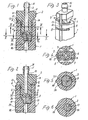
- Figs. 1 to 6 show the venting device in the assembled state, in which the housing 1, the venting element 2 and the sealing element 3 are in their final axial relative position.
- the housing 1 is shown aborted at its lower, the hydraulic system, not shown facing end, because the invention relates only to the area shown.
- the housing 1 has a recess 4 described in more detail below, in which the venting element 2 is inserted, which is limited to a rotation axis 5 limited relative to the housing 1 and the sealing element 3 is rotatable.
- the housing 1 is provided starting from two opposite in the same cross-sectional plane outer grooves 6 with two punctures 7, which serve to receive a formed in the manner of a hairpin spring locking clip 8.
- the securing clasp 8 engages, as best seen in FIG. 4, at opposite locations in a circumferential groove 9 of the venting element 2, which is in the same cross-sectional plane as the two outer grooves 6, and thus secures the venting element 2 against axial movement in the housing 1.
- the housing 1 has, apart from a parallel to the rotation axis 5 extending outer index rib 10, a cylindrical outer shape.
- a corresponding index rib 11 is also located on the venting element 2. If the two index ribs 10, 11 are aligned with each other, as shown in FIGS. 1 and 3, the venting element 2 is in the closed position.
- Part of the index rib 11 on the venting element 2 is a stop lug 12, which two stop surfaces 13 and 14 are assigned to the housing 1.
- the abutment surfaces 13 and 14 are spaced from each other by an angle of rotation of 180 °, so that the stop lug 12 strikes one of the abutment surfaces 13 or 14 after the half-turn of the venting element 2 about the axis of rotation 5.
- the stop surface 13 is the closed position and the stop surface 14 is associated with the venting position.
- vent holes 15, 16 are arranged in alignment with each other in all relative positions between vent element 2 and housing 1.
- the sealing element 3 whose formation is best seen in FIGS. 10 and 11, is non-rotatably inserted into the housing 1 in a manner to be described and has an eccentric but parallel to the axis of rotation 5 through hole 17, the venting of the hydraulic system serves.
- the vent hole 15 has at its the sealing element 3 adjacent end a channel 18, the cross section of which narrows starting from the cross section of the vent hole 15 in the direction of the seal member 3 until its cross section corresponds approximately to the cross section of the through hole 17 in the sealing element 3.
- the channel 18 is at least in its narrowest region with respect to the axis of rotation 5 arranged as eccentric as the through hole 17. In the venting position, the channel 18 and the through hole 17 are aligned with each other, as Fig. 2 illustrates.
- the venting element 2 facing sealing surface 19 of the sealing element 3 is located on a mating surface 20 on the venting element 2, so that under the action of the pressure of the pressure medium in the hydraulic system, the sealing element 3 is pressed with its sealing surface 19 of the mating surface 20 on the venting element 2 self-reinforcing sealing when the venting element 2 is in its closed position (FIG. 1).
- the venting element 2 facing sealing surface 19 of the sealing element 3 is surrounded by a molded-on this tubular segment-shaped annular rib 21, which is arranged coaxially to the axis of rotation 5.
- the annular rib 21 is for recording determined in a complementary annular groove 22 which is formed in the plane-parallel to the sealing surface 19 arranged counter-sealing surface 20 of the venting element 2.
- the through hole 17 in the sealing element 3 is connected in all rotational positions of the venting element 2 to the vent hole 16 in the housing 1 rectilinearly and ends in the sealing surface 19. Accordingly, the narrowing channel 18 of the vent hole 15 of the venting element 2 ends in the mating surface 20th
- a flat surface 23 is provided on the outer circumference of the sealing element 3, which corresponds to a counter surface 24 in the wall surface of the recess 4 in the housing 1.
- the flat surface 23 and the mating surface 24 abut each other when the sealing element 3 is inserted into the housing 1 and prevent rotation of the sealing element 3 relative to the housing 1.
- the sealing element 3 which is formed integrally from a rubber-elastic material, has, in the axial direction, a flange 25 adjoining the annular rib 21 and an essentially cylindrical shank 26 adjoining it.
- the annular rib 21 and the flange 25 are arranged coaxially with each other and to the rotation axis 5, while the shaft 26 is arranged coaxially with the through hole 17.
- the anti-rotation serving flat surface 23 is provided on the flange 25.
- the recess 4 in the housing 1 is formed as a stepped bore.
- the largest diameter of the stepped bore corresponds approximately to the diameter of the area 27 extending into the recess 4 (FIG. 7) of the venting element 2.
- the average diameter of the stepped bore corresponds approximately to the diameter of the flange 25 of the sealing element 3.
- the inner smallest diameter of the stepped bore corresponds approximately the diameter of the cylindrical shaft 26 of the sealing element 3.
- the areas of the largest diameter and the average diameter of the stepped bore are arranged coaxially with each other and coincide with the axis of rotation 5.
- the area of the smallest diameter of the stepped bore is offset from the areas of the largest diameter and the mean diameter of the stepped bore by the amount of eccentricity between the axis of rotation 5 and the through hole 17 in the sealing element 3.
- the sealing element 3 is provided in the region of its shaft 26 with an annular bead 28 integrally formed over the circumference of the shaft.
- the outer diameter of the annular bead 28 is greater than the smallest diameter of the stepped bore in order to achieve a static seal in the inner region of the stepped bore assigned to the shaft 26.
- the annular bead 28 is best seen in Fig. 11.
- the axial length of the inner region of the stepped bore is slightly larger than the axial length of the shaft 26. In this way, an axial gap 29 is formed between the housing 1 and the sealing element 3, as shown in FIGS. 1 and 2. This ensures that the entire lower surface 30 (FIG. 11) of the sealing element 3 acts as a hydraulic active surface for the self-reinforcing pressing of the sealing surface 19 to the mating surface 20 on the venting element 2 is used.
- vent hole 15 in the venting element 2 is guided at the outer end of the same through a breather 31, which is provided for the connection of a hose.
- a venting device for hydraulic systems comprising a connectable to a pressure medium line housing and a vent used in a housing recess, which is rotatable therein between a venting position and a sealing position about a rotation axis and secured against axial movement, wherein a sealing element between housing and venting element seals, and in the housing and venting axial vent holes coaxially with each other, are arranged with the housing recess and with the axis of rotation.
- the sealing element is inserted non-rotatably in the housing and has a respect to the axis of rotation eccentric but parallel through hole, axially aligned in the venting position to a corresponding eccentric Channel of the vent hole connects in the venting element, the latter facing sealing surface of the sealing element is the sealing element in the sealing position under pressure medium acting on the sealing element self-sealingly pressed sealing.
Abstract
Description
Die Erfindung bezieht sich auf eine Entlüftungsvorrichtung für hydraulische Systeme, insbesondere hydraulische Kupplungsbetätigungssysteme für Kraftfahrzeuge, entsprechend dem Oberbegriff des Anspruchs 1.The invention relates to a ventilation device for hydraulic systems, in particular hydraulic clutch actuation systems for motor vehicles, according to the preamble of
Derartige Entlüftungsvorrichtungen dienen der Entlüftung des hydraulischen Systems beim Befüllen mit dem flüssigen Druckmittel. Nach Beendigung des Befüllvorgangs und Entlüftung des hydraulischen Systems über die ventilartige Entlüftungsvorrichtung ist das Entlüftungselement der Entlüftungsvorrichtung von seiner Entlüftungsstellung in seine abgedichtete Schließstellung zu bewegen. In der Schließstellung ist zur Vermeidung unerwünschter Leckagen eine zuverlässige Abdichtung der Entlüftungsvorrichtung erforderlich. Hierbei kommt der Ausbildung und der Anordnung des Dichtungselements eine besondere Bedeutung zu.Such venting devices are used to vent the hydraulic system when filling with the liquid pressure medium. After completion of the filling and venting of the hydraulic system via the valve-like venting device, the venting element of the venting device is to be moved from its venting position into its sealed closed position. In the closed position, a reliable sealing of the venting device is required to avoid unwanted leaks. Here, the training and the arrangement of the sealing element is of particular importance.
Bei einer bekannten Entlüftungsvorrichtung (
Bei einem Ausführungsbeispiel (Fig. 1, 2) dieser bekannten Entlüftungsvorrichtung ist als Dichtungselement ein O-Ring vorgesehen, der in eine ellipsenförmige Umfangsnut des Entlüftungselements eingelegt ist. Dadurch ergibt sich eine labile Montagelage des O-Rings im Vormontagezustand, wodurch der O-Ring bei loser Behälterbevorratung der Entlüftungselemente leicht abgleiten kann. Bei der axialen Montage des Entlüftungselements in der Ausnehmung des Gehäuses können unterschiedliche Pressungen des O-Rings und damit Dichtheitsprobleme auftreten. Außerdem wird der O-Ring beim Drehen des Entlüftungselements in die Entlüftungsstellung über einen in der Gehäusewandung befindlichen Entlüftungsspalt hinwegbewegt, so daß er dabei beschädigt werden kann. Beim Entlüftungsvorgang kann bei Auftreten eines hohen Entlüftungsdruckes der O-Ring in den Entlüftungsspalt verpreßt (Spaltextrusion) und beim nachfolgenden Schließvorgang beschädigt/abgeschert werden.In one embodiment (FIGS. 1, 2) of this known ventilation device, an O-ring is provided as the sealing element, which is inserted into an elliptical circumferential groove of the venting element. This results in a labile mounting position of the O-ring in the pre-assembly state, whereby the O-ring can easily slide off with loose container storage of the venting elements. In the axial mounting of the venting element in the recess of the housing different pressures of the O-ring and thus leakage problems can occur. In addition, the O-ring is moved away when turning the venting element in the venting position over a located in the housing wall vent gap, so that it can be damaged. During the venting process, when a high venting pressure occurs, the O-ring is pressed into the venting gap (gap extrusion) and damaged / sheared off during the subsequent closing operation.
Bei einem anderen Ausführungsbeispiel (Fig. 3) dieser bekannten Entlüftungsvorrichtung ist das Dichtungselement als Schlauchabschnitt ausgebildet, welcher in einem Spaltraum zwischen der zylindrischen Gehäuseinnenfläche und einer zylindrischen Außenfläche des Entlüftungselements angeordnet ist und dabei gegen beide Flächen abdichten soll. Zu diesem Zweck muß offenbar der Schlauchabschnitt gegenüber dem Spaltraum ein Übermaß in seiner Wanddicke aufweisen, so daß er bei der Montage unter erheblichen Kraftaufwand und elastischer Verformung in den Spaltraum einzupressen ist, wodurch nicht nur die Montage erschwert wird, sondern auch die Dichtfunktion beeinträchtigende Beschädigungen auftreten können.In another embodiment (FIG. 3) of this known ventilation device, the sealing element is designed as a tube section, which is arranged in a gap space between the cylindrical housing inner surface and a cylindrical outer surface of the venting element and is intended to seal against both surfaces. For this purpose, obviously the tube portion opposite the gap space must have an excess in its wall thickness, so that it is to be pressed in the assembly under considerable force and elastic deformation in the gap, whereby not only the assembly is difficult, but also the sealing function impairing damage can.
Der Erfindung liegt die Aufgabe zugrunde, eine Entlüftungsvorrichtung bereitzustellen, die einfach herzustellen und zu montieren ist, eine restlose störungsfreie Entlüftung des hydraulischen Systems ermöglicht und im Betrieb des hydraulischen Systems zuverlässig dicht ist.The invention has for its object to provide a ventilation device that is easy to manufacture and assemble, allows a complete trouble-free ventilation of the hydraulic system and is reliable tight during operation of the hydraulic system.
Diese Aufgabe wird erfindungsgemäß durch die im Patentanspruch 1 angegebenen Merkmale gelöst. Vorteilhafte und/oder zweckmäßige Weiterbildungen der Erfindung sind in den Patentansprüchen 2 bis 7 angegeben und werden nachfolgend ebenfalls näher erläutert.This object is achieved by the features specified in
Erfindungsgemäß ist bei einer Entlüftungsvorrichtung für hydraulische Systeme, insbesondere hydraulische Kupplungsbetätigungssysteme für Kraftfahrzeuge, die ein an die Druckmittelleitung anschließbares Gehäuse und ein in eine Ausnehmung des Gehäuses eingesetztes Entlüftungselement umfaßt, das zwischen einer Entlüftungsstellung und einer abgedichteten Stellung im Gehäuse um eine Drehachse begrenzt drehbar und im Gehäuse gegen axiale Bewegungen gesichert ist, wobei ein Dichtungselement zur Abdichtung zwischen dem Gehäuse und dem Entlüftungselement vorgesehen ist, und im Gehäuse und im Entlüftungselement axiale Entlüftungsbohrungen koaxial miteinander, mit der Ausnehmung im Gehäuse und mit der Drehachse angeordnet sind; das Dichtungselement unverdrehbar in das Gehäuse abdichtend eingesetzt und weist eine bezüglich der Drehachse exzentrische aber dazu parallele Durchgangsbohrung auf, die in der Entlüftungsstellung axial fluchtend an einen entsprechend exzentrisch angeordneten Kanal sich verjüngenden Querschnitts der Entlüftungsbohrung im Entlüftungselement anschließt, wobei die dem Entlüftungselement zugekehrte Dichtfläche des Dichtungselements dem Entlüftungselement in dessen abgedichteter Stellung unter der Einwirkung des Druckmittels auf das Dichtungselement selbstverstärkend abdichtend angedrückt ist.According to the invention is in a venting device for hydraulic systems, in particular hydraulic clutch actuation systems for motor vehicles, which includes a pressure medium line connectable to the housing and a vent inserted into a recess of the housing, which rotates between a venting position and a sealed position in the housing about an axis of rotation and in the Housing is secured against axial movement, wherein a sealing element is provided for sealing between the housing and the venting element, and in the housing and in the venting element axial vent holes coaxial with each other, are arranged with the recess in the housing and with the axis of rotation; the seal member is non-rotatably inserted into the housing sealingly and has an axis of rotation with respect to the eccentric but parallel to the through hole in the vent position axially aligned with a correspondingly eccentrically arranged channel tapered cross-section of the vent hole in the vent followed the sealing surface facing the venting element of the sealing element is self-sealingly pressed against the venting element in its sealed position under the action of the pressure medium on the sealing element.
Nach dem Grundgedanken der Erfindung erfolgt die Durchströmung der Entlüftungsvorrichtung beim Entlüftungsvorgang in geradliniger axialer Richtung ohne Strömungsumlenkungen, während in der abgedichteten Schließstellung der auf das Dichtungselement einwirkende Druck des flüssigen Druckmittels das Dichtungselement selbstverstärkend gegen die zugeordneten Dichtungsflächen drückt. Die sich selbstverstärkende Abdichtung ermöglicht eine geringere Vorspannung des gummielastischen Dichtungselements, was zu einer Verringerung der Betätigungskraft bei Drehungen des Entlüftungselements führt. Bei Drehbetätigungen des Entlüftungselements gleiten Stirnflächen des Entlüftungselements und des Dichtungselements, nämlich die Dichtfläche am Dichtungselement und die Gegendichtfläche am Entlüftungselement, drehend aufeinander, so daß dabei die Gefahr von das Dichtungselement möglicherweise beschädigenden Verformungen sehr verringert ist. Bei der Herstellung des erfindungsgemäßen Lüftungselements ergibt sich für seine Spritzformung aus Kunststoff eine Fertigungsvereinfachung, weil mit einer einfachen geteilten Form mit einem Längsschieber zur Erzeugung der axialen Entlüftungsbohrung gearbeitet werden kann, während der Einsatz eines Querschiebers zur Erzeugung von Querausnehmungen wie Querbohrungen vermieden ist.According to the principles of the invention, the flow through the venting device during the venting process in a straight axial direction without flow deflections, while in the sealed closed position of acting on the sealing element pressure of the liquid pressure medium, the sealing element self-energizing presses against the associated sealing surfaces. The self-reinforcing seal allows a lower bias of the rubber-elastic sealing element, resulting in a reduction of the operating force during rotations of the venting element. In rotary actuations of the venting element, end surfaces of the venting element and the sealing element, namely the sealing surface on the sealing element and the mating surface on the venting element, rotate in rotation, thereby greatly reducing the risk of deformations possibly damaging the sealing element. In the production of the ventilation element according to the invention results in its injection molding of plastic manufacturing simplification, because it can be used with a simple split mold with a longitudinal slide to produce the axial vent hole, while the use of a cross slide for generating transverse recesses such as transverse holes is avoided.
Die Entlüftungsvorrichtung kann derart ausgebildet sein, daß die dem Entlüftungselement zugekehrte Dichtfläche des Dichtungselements von einer an dieses angeformten rohrabschnittsförmigen Kreisringrippe umgeben ist, die koaxial zur Drehachse angeordnet ist und die zur Aufnahme in eine komplementäre Ringnut bestimmt ist, welche in die planparallel zur Dichtfläche angeordnete Gegendichtfläche des Entlüftungselements eingeformt ist, und daß die Durchgangsbohrung im Dichtungselement unmittelbar an die Entlüftungsbohrung im Gehäuse geradlinig angeschlossen ist und in der Dichtfläche endet, während der Kanal der Entlüftungsbohrung im Entlüftungselement in der Gegendichtfläche endet. Bei dieser Ausbildung der Entlüftungsvorrichtung kann das Dichtungselement am Entlüftungselement vorteilhaft vormontiert werden, indem die Kreisringrippe des Dichtungselements in die Ringnut des Entlüftungselements eingeführt wird. Das so vormontierte Modul kann dann in entsprechender Drehlage in die Ausnehmung des Gehäuses eingeführt werden. Bei der Drehbetätigung des Entlüftungselements dienen dessen Ringnut und die Kreisringrippe des unverdrehbar im Gehäuse angebrachten Dichtungselements als zusätzliche Führungselemente.The venting device may be formed such that the sealing surface facing the venting element of the sealing element is surrounded by a tubular portion-shaped annular rib formed on this, which is arranged coaxially to the axis of rotation and for receiving in a complementary Annular groove is determined, which is formed in the plane-parallel to the sealing surface arranged counter-sealing surface of the venting element, and that the through-hole in the sealing element is connected directly to the vent hole in the housing straight and ends in the sealing surface, while the channel of the vent hole in the venting element ends in the mating sealing surface. In this embodiment, the venting device, the sealing element can be advantageously pre-assembled on the venting element by the annular rib of the sealing element is inserted into the annular groove of the venting element. The pre-assembled module can then be inserted in a corresponding rotational position in the recess of the housing. During the rotary actuation of the venting element, its annular groove and the annular rib of the sealing element mounted non-rotatably in the housing serve as additional guide elements.
Die Verdrehsicherung des Dichtungselements gegenüber dem Gehäuse kann zweckmäßig durch einfache Mittel, nämlich durch umfänglichen Formschluß unter Einbeziehung eines ebenen Flächenpaares, erreicht werden, indem am Außenumfang des Dichtungselements eine ebene Fläche vorgesehen ist, der eine Gegenfläche in der Wandfläche der Ausnehmung im Gehäuse entspricht, wobei die ebene Fläche und die Gegenfläche aneinanderliegen, wenn das Dichtungselement in das Gehäuse eingesetzt ist.The rotation of the seal member relative to the housing can be conveniently achieved by simple means, namely by circumferential positive engagement involving a flat pair of surfaces by a flat surface is provided on the outer periphery of the seal member, which corresponds to a counter surface in the wall surface of the recess in the housing the flat surface and the mating surface abut each other when the sealing member is inserted into the housing.
Das einteilig aus einem gummielastischen Werkstoff geformte Dichtungselement kann im Verfolg des Erfindungsgedankens in Achsrichtung gesehen eine charakteristische Formgebung haben, nämlich dergestalt, daß das Dichtungselement in axialer Richtung gesehen einen an die Kreisringrippe anschließenden Flansch und einen daran anschließenden im wesentlichen zylindrischen Schaft aufweist, wobei die Kreisringrippe und der Flansch zueinander und zur Drehachse koaxial angeordnet sind, während der Schaft mit der Durchgangsbohrung koaxial angeordnet ist, und wobei die ebene Fläche am Flansch vorgesehen ist. Wesentlich für die Schließfunktion und Öffnungsfunktion der ventilartig zusammenwirkenden Dichtfläche des Dichtungselements mit der Gegendichtfläche des Entlüftungselements ist hier der Exzenterversatz zwischen der Drehachse, bzw. der mit der Drehachse koaxialen Bereiche des Dichtungselements, und der Durchgangsbohrung des Dichtungselements.The one-piece formed from a rubber-elastic material sealing element may have seen in the inventive concept in the axial direction have a characteristic shape, namely such that the sealing element viewed in the axial direction has a subsequent to the annular rib flange and an adjoining substantially cylindrical shaft, wherein the annular rib and the flange to each other and are arranged coaxially to the axis of rotation, while the shaft is arranged coaxially with the through hole, and wherein the flat surface is provided on the flange. Essential for the closing function and opening function of the valve-like cooperating sealing surface of the sealing element with the mating sealing surface of the venting element here is the eccentric offset between the axis of rotation, or with the axis of rotation coaxial areas of the sealing element, and the through hole of the sealing element.
Die Ausnehmung im Gehäuse kann ferner als Stufenbohrung ausgebildet sein, die in ihrem äußeren Bereich dem Entlüftungselement und in ihrem mittleren sowie ihrem inneren Bereich der Formgebung des Dichtungselements komplementär angepaßt ist, indem deren äußerer größter Durchmesser etwa dem Durchmesser des in die Ausnehmung hineinreichenden Bereichs des Entlüftungselements entspricht, deren mittlerer Durchmesser etwa dem Durchmesser des Flansches des Dichtungselements entspricht und deren innerer kleinster Durchmesser etwa dem Durchmesser des zylindrischen Schafts des Dichtungselements entspricht, wobei die Bereiche des größten Durchmessers und des mittleren Durchmessers zueinander koaxial und mit der Drehachse übereinstimmend vorgesehen sind, während der Bereich des kleinsten Durchmessers gegenüber den Bereichen des größten und des mittleren Durchmessers um das Maß der Exzentrizität zwischen der Drehachse und der Durchgangsbohrung im Dichtungselement versetzt angeordnet ist.The recess in the housing may further be formed as a stepped bore which is adapted in its outer region of the venting element and in its middle and its inner region of the shape of the sealing element complementary by their outer largest diameter is approximately the diameter of the reaching into the recess portion of the venting element whose central diameter corresponds approximately to the diameter of the flange of the sealing element and whose inner smallest diameter corresponds approximately to the diameter of the cylindrical shaft of the sealing element, wherein the areas of the largest diameter and the average diameter are provided coaxially with each other and coinciding with the axis of rotation during the Area of smallest diameter relative to the areas of the largest and the average diameter offset by the amount of eccentricity between the axis of rotation and the through hole in the sealing element angeord is net.
Ist das Dichtungselement im Bereich seines Schafts mit einem über den Schaftumfang durchgehend angeformten Ringwulst versehen, dessen Außendurchmesser zur Erzielung einer statischen Abdichtung im inneren Bereich der Stufenbohrung größer ist als der innere kleinste Durchmesser der Stufenbohrung, wird bei Anbringung des Dichtungselements in der Ausnehmung des Gehäuses vorteilhaft eine statische Abdichtung des Dichtungselements gegenüber dem Gehäuse erzielt, indem der am Dichtungselement angeformte Ringwulst bei Einführung des Dichtelements elastisch verformt wird.If the sealing element in the region of its shaft is provided with an annular bead formed integrally over the circumference of the shaft, the outer diameter of which is greater than the inner smallest diameter of the stepped bore in order to achieve a static seal in the inner region of the stepped bore Attachment of the sealing element in the recess of the housing advantageously achieves a static seal of the sealing member relative to the housing by the molded on the sealing element annular bead is elastically deformed upon insertion of the sealing element.
Für die gewünschte selbstverstärkende Abdichtung zwischen Gehäuse und Dichtungselement wird schließlich eine Ausgestaltung der Entlüftungsvorrichtung bevorzugt, bei der die axiale Länge des inneren Bereichs der Stufenbohrung größer ist als die axiale Länge des Schafts des Dichtungselements, so daß ein axialer Spalt zwischen dem Gehäuse und dem Dichtungselement gebildet ist. Aufgrund dieser Spaltbildung steht praktisch die volle untere Stirnfläche des Dichtungselements als hydraulische Wirkfläche zur Verfügung.Finally, for the desired self-reinforcing seal between the housing and the sealing element, an embodiment of the ventilating device is preferred in which the axial length of the inner region of the stepped bore is greater than the axial length of the shaft of the sealing element, so that an axial gap is formed between the housing and the sealing element is. Because of this gap formation is practically the full lower end face of the sealing element as a hydraulic active surface available.
Weitere Einzelheiten der Erfindung werden nachfolgend anhand der ein Ausführungsbeispiel darstellenden Zeichnungen näher erläutert. Darin zeigt:
- Fig. 1
- einen Längsschnitt durch die Entlüftungsvorrichtung in Schließstellung,
- Fig. 2
- den Längsschnitt ähnlich Fig. 1, jedoch in Entlüftungsstellung des Entlüftungselements,
- Fig. 3
- eine perspektivische Außenansicht der Entlüftungsvorrichtung,
- Fig. 4
- den Querschnitt durch die Entlüftungsvorrichtung gemäß der Schnittverlaufslinie IV-IV in Fig. 1,
- Fig. 5
- den Querschnitt durch die Entlüftungsvorrichtung gemäß der Schnittverlaufslinie V-V in Fig. 1,
- Fig. 6
- den Querschnitt durch die Entlüftungsvorrichtung gemäß der Schnittverlaufslinie VI-VI in Fig. 1,
- Fig. 7
- einen Längsschnitt durch das Entlüftungselement in der in Fig. 1 gezeigten Stellung,
- Fig. 8
- eine Seitenansicht des Entlüftungselements,
- Fig. 9
- eine perspektivische Außenansicht des Entlüftungselements,
- Fig. 10
- die Draufsicht auf das Dichtungselement und
- Fig. 11
- den Längsschnitt durch das Dichtungselement entsprechend der Schnittverlaufslinie XI-XI in Fig. 10.
- Fig. 1
- a longitudinal section through the venting device in the closed position,
- Fig. 2
- the longitudinal section similar to FIG. 1, but in the venting position of the venting element,
- Fig. 3
- an external perspective view of the ventilation device,
- Fig. 4
- the cross section through the venting device according to the section line IV-IV in Fig. 1,
- Fig. 5
- 3 shows the cross section through the ventilation device according to the section line VV in FIG. 1,
- Fig. 6
- 3 shows the cross section through the ventilation device according to the section line VI-VI in FIG. 1,
- Fig. 7
- a longitudinal section through the venting element in the position shown in Fig. 1,
- Fig. 8
- a side view of the venting element,
- Fig. 9
- an external perspective view of the venting element,
- Fig. 10
- the top view of the sealing element and
- Fig. 11
- the longitudinal section through the sealing element according to the section line XI-XI in Fig. 10.
Die Fig. 1 bis 6 zeigen die Entlüftungsvorrichtung im fertig montierten Zustand, in welchem sich das Gehäuse 1, das Entlüftungselement 2 und das Dichtungselement 3 in ihrer endgültigen axialen Relativlage befinden. Das Gehäuse 1 ist an seinem unteren, dem nicht dargestellten hydraulischen System zugekehrten Ende abgebrochen dargestellt, weil die Erfindung nur den dargestellten Bereich betrifft.Figs. 1 to 6 show the venting device in the assembled state, in which the
Das Gehäuse 1 besitzt eine weiter unten näher beschriebene Ausnehmung 4, in welche das Entlüftungselement 2 eingesetzt ist, das um eine Drehachse 5 begrenzt relativ zum Gehäuse 1 und zum Dichtungselement 3 drehbar ist. Das Gehäuse 1 ist ausgehend von zwei in derselben Querschnittsebene gegenüberliegenden Außennuten 6 mit zwei Durchstichen 7 versehen, welche der Aufnahme einer nach Art einer Haarnadelfeder ausgebildeten Sicherungsspange 8 dienen. Die Sicherungsspange 8 greift, wie am besten aus Fig. 4 ersichtlich ist, an gegenüberliegenden Stellen in eine Umfangsnut 9 des Entlüftungselements 2, die sich in derselben Querschnittsebene wie die beiden Außennuten 6 befindet, ein und sichert damit das Entlüftungselement 2 gegen axiale Bewegungen im Gehäuse 1.The
Das Gehäuse 1 besitzt, abgesehen von einer parallel zur Drehachse 5 verlaufenden äußeren Indexrippe 10, eine zylindrische Außenform. Eine entsprechende Indexrippe 11 befindet sich auch am Entlüftungselement 2. Wenn die beiden Indexrippen 10, 11 miteinander fluchten, wie das in Fig. 1 und 3 gezeigt ist, befindet sich das Entlüftungselement 2 in Schließstellung. Bestandteil der Indexrippe 11 am Entlüftungselement 2 ist eine Anschlagnase 12, welcher zwei Anschlagflächen 13 und 14 am Gehäuse 1 zugeordnet sind. Die Anschlagflächen 13 und 14 sind um einen Drehwinkel von 180° voneinander entfernt, so daß die Anschlagnase 12 nach jeweils einer halben Drehung des Entlüftungselements 2 um die Drehachse 5 auf eine der Anschlagflächen 13 oder 14 trifft. Die Anschlagfläche 13 ist der Schließstellung und die Anschlagfläche 14 ist der Entlüftungsstellung zugeordnet.The
Im Entlüftungselement 2 und im Gehäuse 1 befindet sich jeweils eine axiale Entlüftungsbohrung 15 bzw. 16, die koaxial miteinander angeordnet sind und deren Mittellinien mit der Drehachse 5 übereinstimmen. Die Entlüftungsbohrungen 15, 16 sind in allen Relativstellungen zwischen Entlüftungselement 2 und Gehäuse 1 miteinander fluchtend angeordnet.In the
Das Dichtungselement 3, dessen Ausbildung am besten aus den Fig. 10 und 11 hervorgeht, ist auf noch zu beschreibende Weise unverdrehbar in das Gehäuse 1 eingesetzt und weist eine bezüglich der Drehachse 5 exzentrische aber dazu parallele Durchgangsbohrung 17 auf, die der Entlüftung des hydraulischen Systems dient. Die Entlüftungsbohrung 15 besitzt an ihrem dem Dichtungselement 3 benachbarten Ende einen Kanal 18, dessen Querschnitt sich ausgehend vom Querschnitt der Entlüftungsbohrung 15 in Richtung auf das Dichtungselement 3 verengt, bis sein Querschnitt etwa dem Querschnitt der Durchgangsbohrung 17 im Dichtungselement 3 entspricht. Der Kanal 18 ist jedenfalls in seinem engsten Bereich bezüglich der Drehachse 5 so exzentrisch angeordnet wie die Durchgangsbohrung 17. In der Entlüftungsstellung sind der Kanal 18 und die Durchgangsbohrung 17 miteinander fluchtend ausgerichtet, wie Fig. 2 verdeutlicht.The sealing
Die dem Entlüftungselement 2 zugekehrte Dichtfläche 19 des Dichtungselements 3 liegt einer Gegendichtfläche 20 am Entlüftungselement 2 an, so daß unter Einwirkung des Druckes des im hydraulischen System befindlichen Druckmittels das Dichtungselement 3 mit seiner Dichtfläche 19 der Gegendichtfläche 20 am Entlüftungselement 2 selbstverstärkend abdichtend angedrückt wird, wenn sich das Entlüftungselement 2 in seiner Schließstellung befindet (Fig. 1).The venting
Die dem Entlüftungselement 2 zugekehrte Dichtfläche 19 des Dichtungselements 3 ist von einer an dieses angeformten rohrabschnittsförmigen Kreisringrippe 21 umgeben, die koaxial zur Drehachse 5 angeordnet ist. Die Kreisringrippe 21 ist zur Aufnahme in eine komplementäre Ringnut 22 bestimmt, welche in die planparallel zur Dichtfläche 19 angeordnete Gegendichtfläche 20 des Entlüftungselements 2 eingeformt ist. Auf diese Weise kann das Dichtungselement 3 am Entlüftungselement 2 vormontiert werden, was die Vereinigung dieser beiden Elemente mit dem Gehäuse 1, d.h. die Einführung dieser Elemente in die Ausnehmung 4 des Gehäuses, sehr erleichtert.The venting
Die Durchgangsbohrung 17 im Dichtungselement 3 ist in allen Drehstellungen des Entlüftungselements 2 an die Entlüftungsbohrung 16 im Gehäuse 1 geradlinig angeschlossen und endet in der Dichtfläche 19. Dementsprechend endet der sich verengende Kanal 18 der Entlüftungsbohrung 15 des Entlüftungselements 2 in der Gegendichtfläche 20.The through
Zur Verdrehsicherung des Dichtungselements 3 im Gehäuse 1 ist am Außenumfang des Dichtungselements 3 eine ebene Fläche 23 vorgesehen, der eine Gegenfläche 24 in der Wandfläche der Ausnehmung 4 im Gehäuse 1 entspricht. Die ebene Fläche 23 und die Gegenfläche 24 liegen aneinander, wenn das Dichtungselement 3 in das Gehäuse 1 eingesetzt ist und verhindern Drehungen des Dichtungselements 3 gegenüber dem Gehäuse 1. Diese Drehsicherungsanordnung ist am deutlichsten aus Fig. 5 entnehmbar.To prevent rotation of the sealing
Wie die Fig. 10 und 11 zeigen, weist das einteilig aus einem gummielastischen Werkstoff geformte Dichtungselement 3 in axialer Richtung gesehen einen an die Kreisringrippe 21 anschließenden Flansch 25 und einen daran anschließenden im wesentlichen zylindrischen Schaft 26 auf. Die Kreisringrippe 21 und der Flansch 25 sind zueinander und zur Drehachse 5 koaxial angeordnet, während der Schaft 26 mit der Durchgangsbohrung 17 koaxial angeordnet ist. Die der Verdrehsicherung dienende ebene Fläche 23 ist am Flansch 25 vorgesehen.As FIGS. 10 and 11 show, the sealing
Die Ausnehmung 4 im Gehäuse 1 ist als Stufenbohrung ausgebildet. Der größte Durchmesser der Stufenbohrung entspricht etwa dem Durchmesser des in die Ausnehmung 4 hineinreichenden Bereichs 27 (Fig. 7) des Entlüftungselements 2. Der mittlere Durchmesser der Stufenbohrung entspricht etwa dem Durchmesser des Flansches 25 des Dichtungselements 3. Der innere kleinste Durchmesser der Stufenbohrung entspricht etwa dem Durchmesser des zylindrischen Schafts 26 des Dichtungselements 3. Die Bereiche des größten Durchmessers und des mittleren Durchmessers der Stufenbohrung sind zueinander koaxial angeordnet und stimmen mit der Drehachse 5 überein. Der Bereich des kleinsten Durchmessers der Stufenbohrung ist dagegen gegenüber den Bereichen des größten Durchmessers und des mittleren Durchmessers der Stufenbohrung um das Maß der Exzentrizität zwischen der Drehachse 5 und der Durchgangsbohrung 17 im Dichtungselement 3 versetzt angeordnet.The
Das Dichtungselement 3 ist im Bereich seines Schafts 26 mit einem über den Schaftumfang durchgehend angeformten Ringwulst 28 versehen. Der Außendurchmesser des Ringwulstes 28 ist zur Erzielung einer statischen Abdichtung im dem Schaft 26 zugeordneten inneren Bereich der Stufenbohrung größer als der kleinste Durchmesser der Stufenbohrung. Der Ringwulst 28 ist am besten in Fig. 11 zu erkennen.The sealing
Die axiale Länge des inneren Bereichs der Stufenbohrung ist etwas größer als die axiale Länge des Schafts 26. Auf diese Weise wird zwischen dem Gehäuse 1 und dem Dichtungselement 3 ein axialer Spalt 29 gebildet, wie aus den Fig. 1 und 2 hervorgeht. Dadurch ist sichergestellt, daß die gesamte untere Fläche 30 (Fig. 11) des Dichtungselements 3 als hydraulische Wirkfläche für die selbstverstärkende Andrückung der Dichtfläche 19 an die Gegendichtfläche 20 am Entlüftungselement 2 dient.The axial length of the inner region of the stepped bore is slightly larger than the axial length of the
Die Entlüftungsbohrung 15 im Entlüftungselement 2 ist am äußeren Ende desselben durch einen Entlüfterstutzen 31 geführt, welcher für den Anschluß eines Schlauchs vorgesehen ist.The
Es wird eine Entlüftungsvorrichtung für Hydrauliksysteme offenbart, umfassend ein an eine Druckmittelleitung anschließbares Gehäuse und ein in eine Gehäuseausnehmung eingesetztes Entlüftungselement, das darin zwischen einer Entlüftungsstellung und einer Dichtstellung um eine Drehachse drehbar und gegen Axialbewegungen gesichert ist, wobei ein Dichtungselement zwischen Gehäuse und Entlüftungselement abdichtet, und im Gehäuse und Entlüftungselement axiale Entlüftungsbohrungen koaxial miteinander, mit der Gehäuseausnehmung und mit der Drehachse angeordnet sind. Um eine einfach herstellbare und montierbare, eine restlose störungsfreie Entlüftung ermöglichende und im Betrieb zuverlässig dichtende Entlüftungsvorrichtung bereitzustellen, ist erfindungsgemäß das Dichtungselement unverdrehbar im Gehäuse eingesetzt und weist eine bezüglich der Drehachse exzentrische aber parallele Durchgangsbohrung auf, die in der Entlüftungsstellung axial fluchtend an einen entsprechend exzentrischen Kanal der Entlüftungsbohrung im Entlüftungselement anschließt, wobei die letzterem zugekehrte Dichtfläche des Dichtungselements dem Entlüftungselement in dessen Dichtstellung unter Druckmitteleinwirkung auf das Dichtungselement selbstverstärkend abdichtend angedrückt ist.There is disclosed a venting device for hydraulic systems, comprising a connectable to a pressure medium line housing and a vent used in a housing recess, which is rotatable therein between a venting position and a sealing position about a rotation axis and secured against axial movement, wherein a sealing element between housing and venting element seals, and in the housing and venting axial vent holes coaxially with each other, are arranged with the housing recess and with the axis of rotation. In order to provide a simple to manufacture and assemble, a residue-free trouble-free venting and reliable sealing in operation venting device according to the invention, the sealing element is inserted non-rotatably in the housing and has a respect to the axis of rotation eccentric but parallel through hole, axially aligned in the venting position to a corresponding eccentric Channel of the vent hole connects in the venting element, the latter facing sealing surface of the sealing element is the sealing element in the sealing position under pressure medium acting on the sealing element self-sealingly pressed sealing.
- 11
- Gehäusecasing
- 22
- EntlüftungselementA vent
- 33
- Dichtungselementsealing element
- 44
- Ausnehmungrecess
- 55
- Drehachseaxis of rotation
- 66
- Außennutouter groove
- 77
- Durchstichpuncture
- 88th
- Sicherungsspangesecuring clip
- 99
- Umfangsnutcircumferential groove
- 1010
- IndexrippeIndex rib
- 1111
- IndexrippeIndex rib
- 1212
- Anschlagnasestop lug
- 1313
- Anschlagflächestop surface
- 1414
- Anschlagflächestop surface
- 1515
- Entlüftungsbohrungvent hole
- 1616
- Entlüftungsbohrungvent hole
- 1717
- DurchgangsbohrungThrough Hole
- 1818
- Kanalchannel
- 1919
- Dichtflächesealing surface
- 2020
- GegendichtflächeAgainst sealing surface
- 2121
- KreisringrippeAnnular rib
- 2222
- Ringnutring groove
- 2323
- ebene Flächeflat surface
- 2424
- Gegenflächecounter surface
- 2525
- Flanschflange
- 2626
- Schaftshaft
- 2727
- BereichArea
- 2828
- Ringwulsttorus
- 2929
- Spaltgap
- 3030
- untere Flächelower surface
- 3131
- EntlüfterstutzenEntlüfterstutzen
Claims (7)
Applications Claiming Priority (1)
| Application Number | Priority Date | Filing Date | Title |
|---|---|---|---|
| DE202006000800U DE202006000800U1 (en) | 2006-01-18 | 2006-01-18 | Ventilation device for hydraulic systems |
Publications (3)
| Publication Number | Publication Date |
|---|---|
| EP1811213A2 true EP1811213A2 (en) | 2007-07-25 |
| EP1811213A3 EP1811213A3 (en) | 2007-08-15 |
| EP1811213B1 EP1811213B1 (en) | 2010-09-08 |
Family
ID=36121230
Family Applications (1)
| Application Number | Title | Priority Date | Filing Date |
|---|---|---|---|
| EP07000153A Active EP1811213B1 (en) | 2006-01-18 | 2007-01-05 | Venting device for hydraulic systems |
Country Status (2)
| Country | Link |
|---|---|
| EP (1) | EP1811213B1 (en) |
| DE (2) | DE202006000800U1 (en) |
Cited By (2)
| Publication number | Priority date | Publication date | Assignee | Title |
|---|---|---|---|---|
| CN104421442A (en) * | 2013-08-30 | 2015-03-18 | 谢夫勒科技股份两合公司 | Sealed air release valve |
| DE102017008854A1 (en) | 2017-09-21 | 2019-03-21 | Fte Automotive Gmbh | Bleed valve for bleeding hydraulic systems for the actuation of in particular clutches and brakes in motor vehicles |
Families Citing this family (1)
| Publication number | Priority date | Publication date | Assignee | Title |
|---|---|---|---|---|
| CN100485235C (en) * | 2007-02-12 | 2009-05-06 | 浙江世进水控股份有限公司 | New type automatic exhaust steam valve |
Citations (1)
| Publication number | Priority date | Publication date | Assignee | Title |
|---|---|---|---|---|
| DE10155793A1 (en) | 2000-11-17 | 2002-08-29 | Luk Lamellen & Kupplungsbau | Hydraulic system for car, e.g. clutch control system, has de-aeration valve comprising de-aeration plug which fits into casing in fluid-tight manner when valve is closed |
Family Cites Families (3)
| Publication number | Priority date | Publication date | Assignee | Title |
|---|---|---|---|---|
| US1511692A (en) * | 1922-03-17 | 1924-10-14 | Vitek Charles | Valve |
| US20050121642A1 (en) * | 2003-12-04 | 2005-06-09 | Purdy Alan H. | Replacement or aftermarket leak-proof brake bleeder |
| WO2006049842A1 (en) * | 2004-10-28 | 2006-05-11 | Pall Corporation | Valve |
-
2006
- 2006-01-18 DE DE202006000800U patent/DE202006000800U1/en not_active Expired - Lifetime
-
2007
- 2007-01-05 DE DE502007004974T patent/DE502007004974D1/en active Active
- 2007-01-05 EP EP07000153A patent/EP1811213B1/en active Active
Patent Citations (1)
| Publication number | Priority date | Publication date | Assignee | Title |
|---|---|---|---|---|
| DE10155793A1 (en) | 2000-11-17 | 2002-08-29 | Luk Lamellen & Kupplungsbau | Hydraulic system for car, e.g. clutch control system, has de-aeration valve comprising de-aeration plug which fits into casing in fluid-tight manner when valve is closed |
Cited By (3)
| Publication number | Priority date | Publication date | Assignee | Title |
|---|---|---|---|---|
| CN104421442A (en) * | 2013-08-30 | 2015-03-18 | 谢夫勒科技股份两合公司 | Sealed air release valve |
| CN104421442B (en) * | 2013-08-30 | 2018-12-18 | 舍弗勒技术股份两合公司 | A kind of sealing deflation valve |
| DE102017008854A1 (en) | 2017-09-21 | 2019-03-21 | Fte Automotive Gmbh | Bleed valve for bleeding hydraulic systems for the actuation of in particular clutches and brakes in motor vehicles |
Also Published As
| Publication number | Publication date |
|---|---|
| DE502007004974D1 (en) | 2010-10-21 |
| EP1811213B1 (en) | 2010-09-08 |
| DE202006000800U1 (en) | 2006-03-16 |
| EP1811213A3 (en) | 2007-08-15 |
Similar Documents
| Publication | Publication Date | Title |
|---|---|---|
| EP3345670B1 (en) | Filter device | |
| EP1454650B1 (en) | Transfer device, in particular for medical fluids | |
| DE102016125134B3 (en) | pinch | |
| DE2709386A1 (en) | ONE-DIRECTIONAL FLOW LIMITER | |
| EP2851596B1 (en) | Wall feedthrough element for a fluid line and wall feedthrough | |
| EP2765344B1 (en) | Coupling unit | |
| DE2427528A1 (en) | THROTTLE VALVE, IN PARTICULAR FOR A VEHICLE COOLING WATER CIRCUIT | |
| EP4127543A1 (en) | Plug-type coupling with pre-assembly locking | |
| DE102009000040A1 (en) | Closing unit for tightly closing a filling and emptying system of rail tank cars or transport tanks | |
| EP1811213B1 (en) | Venting device for hydraulic systems | |
| DE202015103751U1 (en) | pump device | |
| EP2654967B1 (en) | Liquid dispenser | |
| DE10359609A1 (en) | Throttle connection fitting for use in air conduit, has throttle valve that runs diagonally and aligned symmetrically between bearings of valve shaft, where longitudinal axes of valve and seat are normal | |
| EP4060133A1 (en) | Valve assembly, corresponding use and series | |
| DE102006029823B3 (en) | Valve for regulation of the flow of a fluid medium through a heating system or a cooling system has axial pressure-relief slit | |
| DE8124287U1 (en) | Vacuum actuator | |
| DE69820044T2 (en) | THROTTLE | |
| EP1639244B1 (en) | Supplementary control valve device for the inlet channel of a reciprocating internal combustion engine | |
| DE102017008854A1 (en) | Bleed valve for bleeding hydraulic systems for the actuation of in particular clutches and brakes in motor vehicles | |
| EP0386332B1 (en) | Container-draining device | |
| EP2607769A2 (en) | Connection unit and connection assembly comprising such a connection unit for producing a permanent connection between lines containing media | |
| EP0973688A1 (en) | Tap | |
| EP1676061B1 (en) | Throttle valve support | |
| EP3437911B1 (en) | Loading or fuel inlet compartment | |
| DE102009015976A1 (en) | Valve with rotatable valve member |
Legal Events
| Date | Code | Title | Description |
|---|---|---|---|
| PUAI | Public reference made under article 153(3) epc to a published international application that has entered the european phase |
Free format text: ORIGINAL CODE: 0009012 |
|
| PUAL | Search report despatched |
Free format text: ORIGINAL CODE: 0009013 |
|
| AK | Designated contracting states |
Kind code of ref document: A2 Designated state(s): AT BE BG CH CY CZ DE DK EE ES FI FR GB GR HU IE IS IT LI LT LU LV MC NL PL PT RO SE SI SK TR |
|
| AX | Request for extension of the european patent |
Extension state: AL BA HR MK YU |
|
| AK | Designated contracting states |
Kind code of ref document: A3 Designated state(s): AT BE BG CH CY CZ DE DK EE ES FI FR GB GR HU IE IS IT LI LT LU LV MC NL PL PT RO SE SI SK TR |
|
| AX | Request for extension of the european patent |
Extension state: AL BA HR MK YU |
|
| 17P | Request for examination filed |
Effective date: 20080117 |
|
| AKX | Designation fees paid |
Designated state(s): DE FR GB IT |
|
| GRAP | Despatch of communication of intention to grant a patent |
Free format text: ORIGINAL CODE: EPIDOSNIGR1 |
|
| GRAS | Grant fee paid |
Free format text: ORIGINAL CODE: EPIDOSNIGR3 |
|
| GRAA | (expected) grant |
Free format text: ORIGINAL CODE: 0009210 |
|
| AK | Designated contracting states |
Kind code of ref document: B1 Designated state(s): DE FR GB IT |
|
| REG | Reference to a national code |
Ref country code: GB Ref legal event code: FG4D Free format text: NOT ENGLISH |
|
| REF | Corresponds to: |
Ref document number: 502007004974 Country of ref document: DE Date of ref document: 20101021 Kind code of ref document: P |
|
| PLBE | No opposition filed within time limit |
Free format text: ORIGINAL CODE: 0009261 |
|
| STAA | Information on the status of an ep patent application or granted ep patent |
Free format text: STATUS: NO OPPOSITION FILED WITHIN TIME LIMIT |
|
| 26N | No opposition filed |
Effective date: 20110609 |
|
| GBPC | Gb: european patent ceased through non-payment of renewal fee |
Effective date: 20110105 |
|
| REG | Reference to a national code |
Ref country code: DE Ref legal event code: R097 Ref document number: 502007004974 Country of ref document: DE Effective date: 20110609 |
|
| PG25 | Lapsed in a contracting state [announced via postgrant information from national office to epo] |
Ref country code: GB Free format text: LAPSE BECAUSE OF NON-PAYMENT OF DUE FEES Effective date: 20110105 |
|
| REG | Reference to a national code |
Ref country code: FR Ref legal event code: PLFP Year of fee payment: 10 |
|
| REG | Reference to a national code |
Ref country code: FR Ref legal event code: PLFP Year of fee payment: 11 |
|
| REG | Reference to a national code |
Ref country code: FR Ref legal event code: PLFP Year of fee payment: 12 |
|
| PGFP | Annual fee paid to national office [announced via postgrant information from national office to epo] |
Ref country code: IT Payment date: 20220111 Year of fee payment: 16 |
|
| PGFP | Annual fee paid to national office [announced via postgrant information from national office to epo] |
Ref country code: FR Payment date: 20230125 Year of fee payment: 17 |
|
| PGFP | Annual fee paid to national office [announced via postgrant information from national office to epo] |
Ref country code: DE Payment date: 20230112 Year of fee payment: 17 |
|
| P01 | Opt-out of the competence of the unified patent court (upc) registered |
Effective date: 20230629 |
|
| REG | Reference to a national code |
Ref country code: DE Ref legal event code: R081 Ref document number: 502007004974 Country of ref document: DE Owner name: VALEO POWERTRAIN GMBH, DE Free format text: FORMER OWNER: FTE ASIA GMBH, 96106 EBERN, DE Ref country code: DE Ref legal event code: R081 Ref document number: 502007004974 Country of ref document: DE Owner name: VALEO POWERTRAIN GMBH, DE Free format text: FORMER OWNER: FTE AUTOMOTIVE GMBH, 96106 EBERN, DE Ref country code: DE Ref legal event code: R082 Ref document number: 502007004974 Country of ref document: DE Representative=s name: OPPERMANN, MARK, DIPL.-ING., DE |
|
| PG25 | Lapsed in a contracting state [announced via postgrant information from national office to epo] |
Ref country code: IT Free format text: LAPSE BECAUSE OF NON-PAYMENT OF DUE FEES Effective date: 20230105 |