EP1810921A2 - Schiffsantriebsvorrichtung - Google Patents
Schiffsantriebsvorrichtung Download PDFInfo
- Publication number
- EP1810921A2 EP1810921A2 EP07000572A EP07000572A EP1810921A2 EP 1810921 A2 EP1810921 A2 EP 1810921A2 EP 07000572 A EP07000572 A EP 07000572A EP 07000572 A EP07000572 A EP 07000572A EP 1810921 A2 EP1810921 A2 EP 1810921A2
- Authority
- EP
- European Patent Office
- Prior art keywords
- shaft
- propeller
- ship
- clutch
- drive
- Prior art date
- Legal status (The legal status is an assumption and is not a legal conclusion. Google has not performed a legal analysis and makes no representation as to the accuracy of the status listed.)
- Granted
Links
Images
Classifications
-
- B—PERFORMING OPERATIONS; TRANSPORTING
- B63—SHIPS OR OTHER WATERBORNE VESSELS; RELATED EQUIPMENT
- B63H—MARINE PROPULSION OR STEERING
- B63H23/00—Transmitting power from propulsion power plant to propulsive elements
- B63H23/30—Transmitting power from propulsion power plant to propulsive elements characterised by use of clutches
Definitions
- the invention relates to a ship propulsion device according to the features of patent claim 1.
- the overall length is unfavorably increased and the drive system reacts sensitively to displacements of the ship foundations, especially in the case of larger systems.
- the object of the invention is to provide a ship propulsion, which responds less sensitive to relocations of the ship foundations.
- the marine propulsion device according to the invention represents an advantageous space-saving solution for propeller drive torques of about 300,000 Newton meters and more.
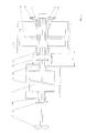
- a propeller 1 is shown, which is connected to a propeller shaft 2 and is provided for the transmission of the ship's propulsion power.
- the propeller shaft 2 is guided in a bearing 14, which is arranged in a housing 13 of a separating clutch 3.
- the separating clutch 3 is mounted completely on an extension of the propeller shaft in the housing 13.
- the housing 13 of the separating clutch 3 is rigidly connected to the ship's foundation.
- the separating clutch 3 is connected via an intermediate shaft 5 with a gear 9 of a gear stage of a transmission.
- an angularly and axially movable coupling 7 is arranged and the intermediate shaft 5 is designed as a flexurally soft torsion shaft, in conjunction with a preferably designed as a diaphragm coupling angle and axially movable coupling 7, the radial and axial displacement between the clutch. 3 and can compensate advantageous transmission without having to provide an additional elastic coupling.
- the gear 9 is preferably arranged on a hollow shaft 6, which is mounted in a housing 10 in bearings 8 and 11.
- the angularly and axially movable Clutch 7 is preferably arranged on the side facing away from the propeller 1 side of the hollow shaft 6 and the intermediate shaft 5 is passed through the hollow shaft 6.
- the gear 9 is connected for example via at least one further gear to a drive.
- a gas turbine or a diesel engine is preferably provided as drive.
- the housing 10 and 13 of the transmission and the separating clutch 3 are arranged so close to each other that the distance s of mutually facing bearings 11 and 12 of the intermediate shaft 5 is at most about eight times the diameter of the intermediate shaft 5.
- the two housings 10, 13 are preferably connected to each other via a flexible oil-tight connection, so that the clutch 3 and the transmission can use a common oil system.
- the intermediate shaft 5 is preferably coupled to the separating clutch 3 via a flange connection.
- a so-called overtaking or synchronous clutch is preferably provided, which can be switched to different operating states.
- a normal position “detachable”, it engages automatically as soon as the prime mover starts up and the drive side of the clutch turns faster than the output side.
- the synchronizer clutch automatically disengages as soon as the output side turns faster than its drive side. This is possible eg in systems with several drive machines.
- the so-called "lock-out” or “locked-out”
- the automatic engagement of the clutch is prevented, so that the prime mover can be raised while the output is still stationary (eg propeller) or the propeller shaft from the clutch output side can be operated by another drive machine (eg an electric drive), wherein the overrunning clutch is then completely inactive.
- a clutch with a different design such as a multi-plate clutch or a dry friction clutch can be used.
- an electric drive not shown, is preferably provided on the propeller shaft 2.
- uncoupled disconnect clutch 3 the ship can be driven solely by this electric drive and perform slow creeping.
- the angularly and axially movable coupling 7 is preferably designed as a diaphragm coupling. It is also conceivable, however, a gear coupling.
- the marine propulsion device according to the invention is particularly advantageous at high propeller drive torques of about 300,000 Newton meters and more.
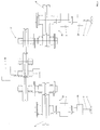
- FIG. 2 shows a ship propulsion system with two propellers, with a ship propulsion device according to the invention being arranged on the propeller shafts.
- the ship propulsion system consists of a main drive 20 - preferably a gas turbine or a diesel engine - which is in driving connection via a transfer case 21 with two ship propulsion devices 22 according to the invention.
- a main drive 20 preferably a gas turbine or a diesel engine - which is in driving connection via a transfer case 21 with two ship propulsion devices 22 according to the invention.
- an electric drive 23 is disposed on the propeller shaft 2 respectively. With disconnected main drive 20, ie when both clutches 3 are disengaged, the ship can be driven alone by the electric drives 23.
Landscapes
- Chemical & Material Sciences (AREA)
- Engineering & Computer Science (AREA)
- Combustion & Propulsion (AREA)
- Mechanical Engineering (AREA)
- Ocean & Marine Engineering (AREA)
- Structure Of Transmissions (AREA)
- Gear Transmission (AREA)
Abstract
Description
- Die Erfindung betrifft eine Schiffsantriebsvorrichtung gemäß den Merkmalen des Patentanspruchs 1.
- Es ist allgemein bekannt, bei Schiffsantriebsanlagen Trennkupplungen vorzusehen, um den Antrieb vom Propeller trennen zu können. Entsprechende Trennkupplungen werden beispielsweise an der Propellerwelle angeordnet oder in ein etwaig vorhandenes Getriebe integriert.
- Durch die Trennkupplung vergrößert sich die Baulänge in ungünstiger Weise und die Antriebsanlage reagiert insbesondere bei größeren Anlagen sensibel auf Verlagerungen des Schiffsfundaments.
- Bei sehr großen Schaltkupplungen können sich Schaltvorgänge durch dynamische Kräfte ungünstig auf die Getriebeverzahnung auswirken.
- Aufgabe der Erfindung ist es, einen Schiffsantrieb zu schaffen, der weniger sensibel auf Verlagerungen des Schiffsfundaments reagiert.
- Diese Aufgabe wird durch die Merkmale des Anspruchs 1 gelöst.
- Durch die erfindungsgemäße Anordnung eines Getriebes und einer Schaltkapplung in separaten Gehäusen sind die Getriebefunktion und die Schaltfunktion voneinander entkoppelt und beeinflussen sich nicht negativ.
- Durch die erfindungsgemäße Anordnung einer winkel- und axialbeweglichen Kupplung wirken sich mögliche Schaltstöße von der Kupplung nicht nachteilig auf die Getriebeverzahnung aus. Ebenso nehmen Verlagerungen des Schiffsfundaments keinen ungünstigen Einfluss auf die Getriebeverzahnung.
- Die erfindungsgemäßen Schiffantriebsvorrichtung stellt eine vorteilhafte platzsparende Lösung für Propellerantriebsdrehmomente von etwa 300000 Newtonmetern und mehr dar.
- Bevorzugte Weiterbildungen der Erfindungen und weitere Vorteile ergeben sich aus den Unteransprüchen in Verbindung mit der nachfolgenden Beschreibung.
- Die Erfindung wird nachfolgend anhand der schematischen Zeichnung näher erläutert. Dabei zeigt die
- Figur 1
- eine erste Ausführung der erfindungsgemäßen Schiffsantriebsvorrichtung und
- Figur 2
- stellt eine erfindungsgemäß ausgeführte Schiffsantriebsanlage dar.
- Aus der schematischen Figur 1 geht ein Propeller 1 hervor, der mit einer Propellerwelle 2 verbunden ist und für die Übertragung der Schiffsantriebsleistung vorgesehen ist. Die Propellerwelle 2 ist in einem Lager 14 geführt, welches in einem Gehäuse 13 einer Trennkupplung 3 angeordnet ist. Die Trennkupplung 3 ist vollständig auf einer Verlängerung der Propellerwelle im Gehäuse 13 gelagert.
- Das Gehäuse 13 der Trennkupplung 3 ist starr mit dem Schiffsfundament verbunden. Die Trennkupplung 3 ist über eine Zwischenwelle 5 mit einem Zahnrad 9 einer Zahnradstufe eines Getriebes verbunden. Zwischen dem Zahnrad 9 und der Zwischenwelle 5 ist eine winkel- und axialbewegliche Kupplung 7 angeordnet und die Zwischenwelle 5 ist als biegeweiche Torsionswelle ausgelegt, die in Verbindung mit einer vorzugsweise als Membrankupplung ausgeführten winkel- und axialbeweglichen Kupplung 7 den radialen und axialen Versatzes zwischen Schaltkupplung 3 und Getriebe vorteilhaft kompensieren kann, ohne eine zusätzliche elastische Kupplung vorsehen zu müssen.
- Das Zahnrad 9 ist vorzugsweise auf einer Hohlwelle 6 angeordnet, die in einem Gehäuse 10 in Lagern 8 und 11 gelagert ist. Die winkel- und axialbewegliche Kupplung 7 ist vorzugsweise an der vom Propeller 1 abgewendeten Seite der Hohlwelle 6 angeordnet und die Zwischenwelle 5 ist durch die Hohlwelle 6 hindurchgeführt.
- Das Zahnrad 9 ist beispielsweise über mindestens ein weiteres Zahnrad mit einem Antrieb verbunden. Als Antrieb wird vorzugsweise eine Gasturbine oder ein Dieselmotor vorgesehen.
- Die Gehäuse 10 und 13 des Getriebes und der Trennkupplung 3 sind so nah zueinander angeordnet, dass der Abstand s der sich zueinander zugewandten Lager 11 und 12 der Zwischenwelle 5 maximal etwa den achtfachen Durchmesser der Zwischenwelle 5 beträgt.
- Die beiden Gehäuse 10, 13 sind vorzugsweise über eine flexible öldichte Verbindung miteinander verbunden, so dass die Kupplung 3 und das Getriebe ein gemeinsames Ölsystem nutzen können.
- Die Zwischenwelle 5 ist vorzugsweise über eine Flanschverbindung an die Trennkupplung 3 angekoppelt.
- Als Trennkupplung 3 wird vorzugsweise eine so genannte Überhol- oder Synchronkupplung vorgesehen, die in verschiedene Betriebszustände geschaltet werden kann. In einer Normalstellung "kuppelbar" rückt sie automatisch ein, sobald die Antriebsmaschine hochläuft und die Antriebsseite der Kupplung schneller dreht als die Abtriebsseite. Die Synchronkupplung rückt automatisch aus, sobald die Abtriebsseite schneller dreht als ihre Antriebsseite. Dies ist z.B. bei Anlagen mit mehreren Antriebsmaschinen möglich. In einer weiteren Stellung, der so genannten "Aus-Blockierung" (oder "locked-out") wird das automatische Einrücken der Kupplung verhindert, so dass die Antriebsmaschine bei weiterhin stillstehendem Abtrieb (z.B. Propeller) hochgefahren werden kann oder die Propellerwelle von der Kupplungsabtriebsseite her von einer weitere Antriebsmaschine (z.B. einem Elektroantrieb) betrieben werden kann, wobei die Überholkupplung dann völlig inaktiv ist.
- Als Trennkupplung 3 kann selbstverständlich auch eine Kupplung mit anderer Bauart, wie beispielsweise eine Lamellenkupplung oder eine Trockenreibkupplung verwendet werden.
- Zwischen der Trennkupplung 3 und dem Propeller 1 ist an der Propellerwelle 2 vorzugsweise ein nicht dargestellter Elektroantrieb vorgesehen. Bei abgekoppelter Trennkupplung 3 kann das Schiff alleine durch diesen Elektroantrieb angetrieben werden und langsame Schleichfahrten ausführen.
- Die winkel- sowie axialbewegliche Kupplung 7 wird vorzugsweise als Membrankupplung ausgeführt. Denkbar ist jedoch auch eine Zahnkupplung.
- Die erfindungsgemäße Schiffsantriebsvorrichtung ist besonders vorteilhaft bei großen Propellerantriebsdrehmomenten von etwa 300000 Newtonmeter und mehr.
- In Figur 2 ist eine Schiffsantriebsanlage mit zwei Propellern dargestellt, wobei an den Propellerwellen jeweils eine erfindungsgemäße Schiffsantriebsvorrichtung angeordnet ist. Die Schiffsantriebsanlage besteht aus einem Hauptantrieb 20 - vorzugsweise einer Gasturbine oder einem Dieselmotor -, der über ein Verteilergetriebe 21 mit zwei erfindungsgemäßen Schiffsantriebsvorrichtungen 22 in Antriebsverbindung steht. Zwischen den Trennkupplungen 3 und den Propellern 1 ist jeweils ein Elektroantrieb 23 an der Propellerwelle 2 angeordnet. Bei abgekoppeltem Hauptantrieb 20, d.h. wenn beide Kupplungen 3 ausgerückt sind, kann das Schiff alleine durch die Elektroantriebe 23 gefahren werden.
-
- 1
- Propeller
- 2
- Propellerwelle
- 3
- Trennkupplung
- 4
- Gehäuseverbindung
- 5
- Zwischenwelle (Torsionswelle)
- 6
- Hohlwelle
- 7
- winkel- und axialbewegliche Kupplung
- 8
- Lager
- 9
- Zahnrad
- 10
- Gehäuse
- 11
- Lager
- 12
- Lager
- 13
- Gehäuse
- 14
- Lager
- 20
- Hauptantrieb
- 21
- Verteilergetriebe
- 22
- Schiffsantriebsvorrichtung
- 23
- Elektroantrieb
Claims (7)
- Schiffsantriebsvorrichtung, insbesondere für große Propellerdrehmomente, mit mindestens einer Zahnradstufe (9) zwischen Antrieb und Propeller (1) und einer winkel- sowie axialbeweglichen Kupplung (7) zwischen der Zahnradstufe (9) und einer Trennkupplung (3), die den Antrieb vom Propeller (1) abkuppeln kann, dadurch gekennzeichnet, dass die Trennkupplung (3) und die mindestens eine Zahnradstufe (9) in getrennten Gehäusen (10, 13) angeordnet sind, wobei das Gehäuse (13) der Trennkupplung (3) starr mit dem Schiffsfundament verbunden ist und die beiden Gehäuse (10, 13) bezüglich der sich zugewandten Lagerungen (11, 12) einer Welle (5) einen maximalen Abstand (5) von etwa dem achtfachen Durchmesser der Welle (5) aufweisen.
- Schiffsantriebsvorrichtung nach Anspruch 1, dadurch gekennzeichnet, dass die winkel- und axialbewegliche Kupplung (7) als Membrankupplung oder als Zahnkupplung ausgeführt ist.
- Schiffsantriebsvorrichtung nach Anspruch 2, dadurch gekennzeichnet, dass ein über die Welle (5) mit der Propellerwelle verbundenes Zahnrad (9) auf einer Hohlwelle (6) angeordnet ist und die winkel- sowie axialbewegliche Kupplung (7) an der von der Propellerwelle (2) abgewendeten Seite der Hohlwelle (6) angeordnet ist, wo sie die Welle (5) mit der Hohlwelle (6) verbindet und die Welle (5) durch die Hohlwelle (6) geführt ist.
- Schiffsantriebsvorrichtung nach einem der vorhergehenden Ansprüche, dadurch gekennzeichnet, dass die Trennkupplung (3) als Lamellenkupplung, Trockenreibkupplung oder als selbst ein- und auskuppelnde Synchronkupplung ausgeführt ist.
- Schiffsantriebsvorrichtung nach einem der vorhergehenden Ansprüche, dadurch gekennzeichnet, dass die Gehäuseinnenräume der mindestens zwei Gehäuse (10, 13) mit elastischen Mitteln miteinander verbunden sind, so dass sie ein gemeinsames Ölsystem nutzen können.
- Schiffsantriebsvorrichtung nach einem der vorhergehenden Ansprüche, dadurch gekennzeichnet, dass die Antriebseinrichtung über mehrere Untersetzungsstufen an eine Hauptantriebseinrichtung (20), insbesondere eine Gasturbine, angekoppelt ist und zwischen der Trennkupplung (3) und dem Propeller (1) ein Elektromotor (23) als weiterer Antrieb vorgesehen ist.
- Schiffsantriebsvorrichtung nach einem der Ansprüche 1 bis 6, dadurch gekennzeichnet, dass zwei der Schiffsantriebseinrichtungen über ein Verteilergetriebe (21) und mindestens eine Übersetzungsstufe an eine Hauptantriebseinrichtung (20), insbesondere eine Gasturbine angekoppelt sind und zwischen den Trennkupplungen (3) und den Propellern (1) jeweils ein Elektromotor (23) als weiterer Antrieb vorgesehen ist.
Applications Claiming Priority (1)
| Application Number | Priority Date | Filing Date | Title |
|---|---|---|---|
| DE200610002572 DE102006002572B4 (de) | 2006-01-18 | 2006-01-18 | Schiffsantriebsvorrichtung |
Publications (3)
| Publication Number | Publication Date |
|---|---|
| EP1810921A2 true EP1810921A2 (de) | 2007-07-25 |
| EP1810921A3 EP1810921A3 (de) | 2011-01-19 |
| EP1810921B1 EP1810921B1 (de) | 2014-12-03 |
Family
ID=37946300
Family Applications (1)
| Application Number | Title | Priority Date | Filing Date |
|---|---|---|---|
| EP20070000572 Ceased EP1810921B1 (de) | 2006-01-18 | 2007-01-12 | Schiffsantriebsvorrichtung |
Country Status (2)
| Country | Link |
|---|---|
| EP (1) | EP1810921B1 (de) |
| DE (1) | DE102006002572B4 (de) |
Citations (1)
| Publication number | Priority date | Publication date | Assignee | Title |
|---|---|---|---|---|
| EP0036028A1 (de) | 1980-03-13 | 1981-09-23 | Aktien-Gesellschaft "Weser" | Schiffsantrieb mit hydrodynamischer Kupplung |
Family Cites Families (12)
| Publication number | Priority date | Publication date | Assignee | Title |
|---|---|---|---|---|
| GB123237A (en) * | 1918-04-29 | 1919-02-20 | Eugene Bivert | Improvements in Marine Motors of the Outboard or Portable Type. |
| US1886191A (en) * | 1928-04-04 | 1932-11-01 | Johnson Brothers Engineering C | Shock absorbing device for outboard motor drives |
| GB843633A (en) * | 1957-01-30 | 1960-08-04 | Vincent Engineers Stevenage Lt | Improvements in or relating to power transmissions for the propeller shafts of boats |
| DE3029336C2 (de) * | 1980-08-01 | 1983-12-15 | Zahnräderfabrik Renk AG, 8900 Augsburg | Antriebsanlage, insbesondere Schiffsantrieb |
| US4820209A (en) * | 1987-11-09 | 1989-04-11 | Brunswick Corporation | Torque converter marine transmission with variable power output |
| DE19756420C2 (de) * | 1997-12-18 | 2001-09-20 | Man B & W Diesel As Kopenhagen | Antriebsvorrichtung |
| DE19920924C2 (de) * | 1999-05-06 | 2002-11-21 | Renk Ag | Schiffsantrieb mit lastschaltbarer Kupplungsanordnung |
| DE10020434A1 (de) * | 2000-04-26 | 2001-10-31 | Constantin M Gallin | Schiffantriebsanlage für sicheren, wirkungsvollen und anpassungsfähigen Betrieb |
| DE10135711A1 (de) * | 2001-07-21 | 2003-02-06 | Fr Fassmer Gmbh & Co | Antriebsstrang für Schiffe und Verfahren zu seinem Betreiben |
| DE10235286B4 (de) * | 2002-08-02 | 2005-02-10 | Renk Aktiengesellschaft | Propellerwellen-Schaltkupplung für einen Schiffsantrieb |
| US6960107B1 (en) * | 2004-04-16 | 2005-11-01 | Brunswick Corporation | Marine transmission with a cone clutch used for direct transfer of torque |
| US6966805B1 (en) * | 2004-06-10 | 2005-11-22 | Brunswick Corporation | Marine transmission with synchronized engagement of a dog clutch |
-
2006
- 2006-01-18 DE DE200610002572 patent/DE102006002572B4/de not_active Expired - Fee Related
-
2007
- 2007-01-12 EP EP20070000572 patent/EP1810921B1/de not_active Ceased
Patent Citations (1)
| Publication number | Priority date | Publication date | Assignee | Title |
|---|---|---|---|---|
| EP0036028A1 (de) | 1980-03-13 | 1981-09-23 | Aktien-Gesellschaft "Weser" | Schiffsantrieb mit hydrodynamischer Kupplung |
Also Published As
| Publication number | Publication date |
|---|---|
| EP1810921B1 (de) | 2014-12-03 |
| EP1810921A3 (de) | 2011-01-19 |
| DE102006002572B4 (de) | 2008-01-24 |
| DE102006002572A1 (de) | 2007-07-26 |
Similar Documents
| Publication | Publication Date | Title |
|---|---|---|
| DE60212220T2 (de) | Bewegungsübertragungsvorrichtung für Hybridfahrzeuge | |
| DE102010061062B4 (de) | Baukastensystem | |
| WO2005068800A1 (de) | Antriebskraftübertragungsvorrichtung mit hydrodynamischer gegenlaufkupplung | |
| DE102018101270A1 (de) | Antriebsvorrichtung mit einer elektrischen Maschine | |
| DE102018112405B3 (de) | Antriebsvorrichtung mit einer elektrischen Maschine | |
| DE3046679C2 (de) | Abzweiggetriebe für einen Schiffsantrieb | |
| EP1532383B1 (de) | Getriebe mit direktem gang | |
| EP1810921B1 (de) | Schiffsantriebsvorrichtung | |
| DE102008005351B4 (de) | Drehmomentübertragungsvorrichtung für ein Schiff | |
| EP2285614B1 (de) | Vorrichtung zur Erzeugung und Übertragung eines Antriebsdrehmoments | |
| EP3279081A1 (de) | Schiffsantriebssystem | |
| DE102012208065A1 (de) | Schiffsantriebssystem | |
| DE102012012106A1 (de) | Windkraftanlage mit einem zwischen Planetengetriebeund Generator angeordneten Kupplungsmittel zumAusgleich von Axial-, Radial- und Winkelversatz | |
| DE102020123917A1 (de) | Kupplungsanordnung und Schaltanordnung | |
| DE102014208157A1 (de) | Hydrodynamisches Anfahrelement mit einem gegenüber einem Gehäuse verdrehbaren Pumpenrad | |
| DE10005538A1 (de) | Bootsantrieb | |
| DE102017211551B4 (de) | Schiffsgetriebe | |
| DE102021213011B3 (de) | Differential mit zweigeteilten Abtriebsseitenrad | |
| DE102016005804B4 (de) | Antriebseinrichtung für ein Kraftfahrzeug sowie Verfahren zum Betreiben einer Antriebseinrichtung | |
| DE10034745B4 (de) | Vorrichtung zum Betätigen zweier Kupplungen | |
| EP1525412B1 (de) | Anordnung des zwischenrads für den rückwärtsgang für ein getriebe mit nebenabtriebsbetrieb | |
| DE102016217607A1 (de) | Elektrische Achsenanordnung mit vollintegrierter Kupplung | |
| DE102005032301A1 (de) | Innen und außen kerbverzahnte Kupplungsnabe für Drehmomentübertragungsmechanismen in einem Lastschaltgetriebe | |
| DE102008002554A1 (de) | Doppelkupplungsgetriebe | |
| DE102012218912A1 (de) | Getriebe mit einem Grundgetriebe und schaltbarem Nebenabtrieb für einen Schiffsantrieb |
Legal Events
| Date | Code | Title | Description |
|---|---|---|---|
| PUAI | Public reference made under article 153(3) epc to a published international application that has entered the european phase |
Free format text: ORIGINAL CODE: 0009012 |
|
| AK | Designated contracting states |
Kind code of ref document: A2 Designated state(s): AT BE BG CH CY CZ DE DK EE ES FI FR GB GR HU IE IS IT LI LT LU LV MC NL PL PT RO SE SI SK TR |
|
| AX | Request for extension of the european patent |
Extension state: AL BA HR MK YU |
|
| PUAL | Search report despatched |
Free format text: ORIGINAL CODE: 0009013 |
|
| AK | Designated contracting states |
Kind code of ref document: A3 Designated state(s): AT BE BG CH CY CZ DE DK EE ES FI FR GB GR HU IE IS IT LI LT LU LV MC NL PL PT RO SE SI SK TR |
|
| AX | Request for extension of the european patent |
Extension state: AL BA HR MK RS |
|
| 17P | Request for examination filed |
Effective date: 20110704 |
|
| AKX | Designation fees paid |
Designated state(s): FR IT |
|
| REG | Reference to a national code |
Ref country code: DE Ref legal event code: R108 Effective date: 20110921 |
|
| 17Q | First examination report despatched |
Effective date: 20111117 |
|
| GRAP | Despatch of communication of intention to grant a patent |
Free format text: ORIGINAL CODE: EPIDOSNIGR1 |
|
| INTG | Intention to grant announced |
Effective date: 20140226 |
|
| GRAS | Grant fee paid |
Free format text: ORIGINAL CODE: EPIDOSNIGR3 |
|
| GRAA | (expected) grant |
Free format text: ORIGINAL CODE: 0009210 |
|
| AK | Designated contracting states |
Kind code of ref document: B1 Designated state(s): FR IT |
|
| PLBE | No opposition filed within time limit |
Free format text: ORIGINAL CODE: 0009261 |
|
| STAA | Information on the status of an ep patent application or granted ep patent |
Free format text: STATUS: NO OPPOSITION FILED WITHIN TIME LIMIT |
|
| 26N | No opposition filed |
Effective date: 20150904 |
|
| REG | Reference to a national code |
Ref country code: FR Ref legal event code: PLFP Year of fee payment: 10 |
|
| REG | Reference to a national code |
Ref country code: FR Ref legal event code: PLFP Year of fee payment: 11 |
|
| REG | Reference to a national code |
Ref country code: FR Ref legal event code: PLFP Year of fee payment: 12 |
|
| PGFP | Annual fee paid to national office [announced via postgrant information from national office to epo] |
Ref country code: IT Payment date: 20240129 Year of fee payment: 18 Ref country code: FR Payment date: 20240124 Year of fee payment: 18 |
|
| PG25 | Lapsed in a contracting state [announced via postgrant information from national office to epo] |
Ref country code: FR Free format text: LAPSE BECAUSE OF NON-PAYMENT OF DUE FEES Effective date: 20250131 |
|
| PG25 | Lapsed in a contracting state [announced via postgrant information from national office to epo] |
Ref country code: IT Free format text: LAPSE BECAUSE OF NON-PAYMENT OF DUE FEES Effective date: 20250112 |