EP1809881B1 - Control apparatus for internal combustion engine - Google Patents
Control apparatus for internal combustion engine Download PDFInfo
- Publication number
- EP1809881B1 EP1809881B1 EP20050803171 EP05803171A EP1809881B1 EP 1809881 B1 EP1809881 B1 EP 1809881B1 EP 20050803171 EP20050803171 EP 20050803171 EP 05803171 A EP05803171 A EP 05803171A EP 1809881 B1 EP1809881 B1 EP 1809881B1
- Authority
- EP
- European Patent Office
- Prior art keywords
- fuel injection
- engine
- internal combustion
- fuel
- combustion engine
- Prior art date
- Legal status (The legal status is an assumption and is not a legal conclusion. Google has not performed a legal analysis and makes no representation as to the accuracy of the status listed.)
- Not-in-force
Links
Images

Classifications
-
- F—MECHANICAL ENGINEERING; LIGHTING; HEATING; WEAPONS; BLASTING
- F02—COMBUSTION ENGINES; HOT-GAS OR COMBUSTION-PRODUCT ENGINE PLANTS
- F02M—SUPPLYING COMBUSTION ENGINES IN GENERAL WITH COMBUSTIBLE MIXTURES OR CONSTITUENTS THEREOF
- F02M63/00—Other fuel-injection apparatus having pertinent characteristics not provided for in groups F02M39/00 - F02M57/00 or F02M67/00; Details, component parts, or accessories of fuel-injection apparatus, not provided for in, or of interest apart from, the apparatus of groups F02M39/00 - F02M61/00 or F02M67/00; Combination of fuel pump with other devices, e.g. lubricating oil pump
- F02M63/02—Fuel-injection apparatus having several injectors fed by a common pumping element, or having several pumping elements feeding a common injector; Fuel-injection apparatus having provisions for cutting-out pumps, pumping elements, or injectors; Fuel-injection apparatus having provisions for variably interconnecting pumping elements and injectors alternatively
- F02M63/0225—Fuel-injection apparatus having a common rail feeding several injectors ; Means for varying pressure in common rails; Pumps feeding common rails
- F02M63/0275—Arrangement of common rails
- F02M63/0285—Arrangement of common rails having more than one common rail
- F02M63/029—Arrangement of common rails having more than one common rail per cylinder bank, e.g. storing different fuels or fuels at different pressure levels per cylinder bank
-
- F—MECHANICAL ENGINEERING; LIGHTING; HEATING; WEAPONS; BLASTING
- F02—COMBUSTION ENGINES; HOT-GAS OR COMBUSTION-PRODUCT ENGINE PLANTS
- F02D—CONTROLLING COMBUSTION ENGINES
- F02D41/00—Electrical control of supply of combustible mixture or its constituents
- F02D41/30—Controlling fuel injection
-
- F—MECHANICAL ENGINEERING; LIGHTING; HEATING; WEAPONS; BLASTING
- F02—COMBUSTION ENGINES; HOT-GAS OR COMBUSTION-PRODUCT ENGINE PLANTS
- F02D—CONTROLLING COMBUSTION ENGINES
- F02D41/00—Electrical control of supply of combustible mixture or its constituents
- F02D41/02—Circuit arrangements for generating control signals
- F02D41/021—Introducing corrections for particular conditions exterior to the engine
- F02D41/0235—Introducing corrections for particular conditions exterior to the engine in relation with the state of the exhaust gas treating apparatus
- F02D41/024—Introducing corrections for particular conditions exterior to the engine in relation with the state of the exhaust gas treating apparatus to increase temperature of the exhaust gas treating apparatus
-
- F—MECHANICAL ENGINEERING; LIGHTING; HEATING; WEAPONS; BLASTING
- F02—COMBUSTION ENGINES; HOT-GAS OR COMBUSTION-PRODUCT ENGINE PLANTS
- F02D—CONTROLLING COMBUSTION ENGINES
- F02D41/00—Electrical control of supply of combustible mixture or its constituents
- F02D41/30—Controlling fuel injection
- F02D41/3011—Controlling fuel injection according to or using specific or several modes of combustion
- F02D41/3017—Controlling fuel injection according to or using specific or several modes of combustion characterised by the mode(s) being used
- F02D41/3023—Controlling fuel injection according to or using specific or several modes of combustion characterised by the mode(s) being used a mode being the stratified charge spark-ignited mode
- F02D41/3029—Controlling fuel injection according to or using specific or several modes of combustion characterised by the mode(s) being used a mode being the stratified charge spark-ignited mode further comprising a homogeneous charge spark-ignited mode
-
- F—MECHANICAL ENGINEERING; LIGHTING; HEATING; WEAPONS; BLASTING
- F02—COMBUSTION ENGINES; HOT-GAS OR COMBUSTION-PRODUCT ENGINE PLANTS
- F02D—CONTROLLING COMBUSTION ENGINES
- F02D41/00—Electrical control of supply of combustible mixture or its constituents
- F02D41/30—Controlling fuel injection
- F02D41/3094—Controlling fuel injection the fuel injection being effected by at least two different injectors, e.g. one in the intake manifold and one in the cylinder
-
- F—MECHANICAL ENGINEERING; LIGHTING; HEATING; WEAPONS; BLASTING
- F02—COMBUSTION ENGINES; HOT-GAS OR COMBUSTION-PRODUCT ENGINE PLANTS
- F02M—SUPPLYING COMBUSTION ENGINES IN GENERAL WITH COMBUSTIBLE MIXTURES OR CONSTITUENTS THEREOF
- F02M69/00—Low-pressure fuel-injection apparatus ; Apparatus with both continuous and intermittent injection; Apparatus injecting different types of fuel
- F02M69/04—Injectors peculiar thereto
- F02M69/042—Positioning of injectors with respect to engine, e.g. in the air intake conduit
- F02M69/046—Positioning of injectors with respect to engine, e.g. in the air intake conduit for injecting into both the combustion chamber and the intake conduit
-
- F—MECHANICAL ENGINEERING; LIGHTING; HEATING; WEAPONS; BLASTING
- F01—MACHINES OR ENGINES IN GENERAL; ENGINE PLANTS IN GENERAL; STEAM ENGINES
- F01N—GAS-FLOW SILENCERS OR EXHAUST APPARATUS FOR MACHINES OR ENGINES IN GENERAL; GAS-FLOW SILENCERS OR EXHAUST APPARATUS FOR INTERNAL COMBUSTION ENGINES
- F01N3/00—Exhaust or silencing apparatus having means for purifying, rendering innocuous, or otherwise treating exhaust
- F01N3/08—Exhaust or silencing apparatus having means for purifying, rendering innocuous, or otherwise treating exhaust for rendering innocuous
- F01N3/10—Exhaust or silencing apparatus having means for purifying, rendering innocuous, or otherwise treating exhaust for rendering innocuous by thermal or catalytic conversion of noxious components of exhaust
- F01N3/24—Exhaust or silencing apparatus having means for purifying, rendering innocuous, or otherwise treating exhaust for rendering innocuous by thermal or catalytic conversion of noxious components of exhaust characterised by constructional aspects of converting apparatus
- F01N3/28—Construction of catalytic reactors
-
- F—MECHANICAL ENGINEERING; LIGHTING; HEATING; WEAPONS; BLASTING
- F02—COMBUSTION ENGINES; HOT-GAS OR COMBUSTION-PRODUCT ENGINE PLANTS
- F02D—CONTROLLING COMBUSTION ENGINES
- F02D41/00—Electrical control of supply of combustible mixture or its constituents
- F02D41/30—Controlling fuel injection
- F02D41/3011—Controlling fuel injection according to or using specific or several modes of combustion
- F02D41/3076—Controlling fuel injection according to or using specific or several modes of combustion with special conditions for selecting a mode of combustion, e.g. for starting, for diagnosing
-
- F—MECHANICAL ENGINEERING; LIGHTING; HEATING; WEAPONS; BLASTING
- F02—COMBUSTION ENGINES; HOT-GAS OR COMBUSTION-PRODUCT ENGINE PLANTS
- F02M—SUPPLYING COMBUSTION ENGINES IN GENERAL WITH COMBUSTIBLE MIXTURES OR CONSTITUENTS THEREOF
- F02M69/00—Low-pressure fuel-injection apparatus ; Apparatus with both continuous and intermittent injection; Apparatus injecting different types of fuel
- F02M69/46—Details, component parts or accessories not provided for in, or of interest apart from, the apparatus covered by groups F02M69/02 - F02M69/44
- F02M69/462—Arrangement of fuel conduits, e.g. with valves for maintaining pressure in the pipes after the engine being shut-down
-
- Y—GENERAL TAGGING OF NEW TECHNOLOGICAL DEVELOPMENTS; GENERAL TAGGING OF CROSS-SECTIONAL TECHNOLOGIES SPANNING OVER SEVERAL SECTIONS OF THE IPC; TECHNICAL SUBJECTS COVERED BY FORMER USPC CROSS-REFERENCE ART COLLECTIONS [XRACs] AND DIGESTS
- Y02—TECHNOLOGIES OR APPLICATIONS FOR MITIGATION OR ADAPTATION AGAINST CLIMATE CHANGE
- Y02T—CLIMATE CHANGE MITIGATION TECHNOLOGIES RELATED TO TRANSPORTATION
- Y02T10/00—Road transport of goods or passengers
- Y02T10/10—Internal combustion engine [ICE] based vehicles
- Y02T10/12—Improving ICE efficiencies
Definitions
- the present invention relates to a control apparatus for an internal combustion engine having a first fuel injection mechanism (an in-cylinder injector) for injecting a fuel into a cylinder and a second fuel injection mechanism (an intake manifold injector) for injecting a fuel into an intake manifold or an intake port, and relates particularly to a technique for determining a fuel injection ratio between the first and second fuel injection mechanisms.
- a first fuel injection mechanism an in-cylinder injector
- an intake manifold injector for injecting a fuel into an intake manifold or an intake port
- An internal combustion engine having a first fuel injection valve (an intake manifold injector in the background art) for injecting a fuel into an intake manifold of the engine and a second fuel injection valve (an in-cylinder injector in the background art) for always injecting a fuel into a combustion chamber of the engine, and configured to stop fuel injection from the first fuel injection valve (the intake manifold injector) when the engine load is lower than a preset load and to cause fuel injection from the first fuel injection valve (the intake manifold injector) when the engine load is higher than the set load, is known.
- one configured to switch between stratified charge combustion and homogeneous combustion in accordance with its operation state is known.
- the fuel is injected from the in-cylinder injector during a compression stroke to form a stratified air-fuel mixture locally around a spark plug, for lean combustion of the fuel.
- the fuel is diffused in the combustion chamber to form a homogeneous air-fuel mixture, for combustion of the fuel.
- Japanese Patent Laying-Open No. JP 2001-020837 A discloses a fuel injection control apparatus for an engine that switches between stratified charge combustion and homogeneous combustion in accordance with an operation state and that has a main fuel injection valve for injecting a fuel directly into a combustion chamber and a secondary fuel injection valve for injecting a fuel into an intake port of each cylinder.
- This fuel injection control apparatus for the engine is characterized in that the fuel injection ratio between the main fuel injection valve and the secondary fuel injection valve is set in a variable manner based on an operation state of the engine.
- the stratified charge combustion is carried out using only the main fuel injection valve directly injecting the fuel into the combustion chamber, while the homogeneous combustion is carried out using both the main fuel injection valve and the secondary fuel injection valve (or using only the secondary fuel injection valve in some cases).
- This can keep the capacity of the main fuel injection valve small, even in the case of an engine of high power.
- Linearity in injection duration/injection quantity characteristic of the main fuel injection valve in a low-load region such as during idling is improved, which in turn improves accuracy in control of the fuel injection quantity. Accordingly, it is possible to maintain favorable stratified charge combustion, and thus to improve stability of the low-load operation such as idling.
- both the main and secondary fuel injection valves are employed, so that the benefit of the direct fuel injection and the benefit of the intake port injection are both enjoyed. Accordingly, favorable homogeneous combustion can also be maintained.
- the stratified charge combustion and the homogeneous combustion are employed according to the situations, which complicates ignition control, injection control and throttle control, and requires control programs corresponding to the respective combustion manners. Particularly, upon switching between the combustion manners, these controls require considerable changes, making it difficult to realize desirable controls (of fuel efficiency, emission purification performance) at the time of transition. Further, in the stratified combustion region where lean combustion is carried out, the three-way catalyst does not work, in which case a lean NOx catalyst needs to be used, leading to an increased cost.
- a direct injection engine which has only an in-cylinder injector to carry out homogeneous combustion over the entire region, with no stratified charge combustion conducted, and thus does not need control for switching between the stratified charge combustion and the homogeneous combustion and does not require an expensive lean NOx catalyst.
- Japanese Patent Laying-Open No. JP 2001-020837 A described above merely discloses that in the region where homogeneous combustion is carried out, a ratio of the quantity of the fuel injected from the secondary fuel injection valve injecting the fuel into the intake port with respect to the total quantity of the fuel injected is increased in accordance with an increase of the engine output (engine speed and load), which cannot provide solutions to the above-described problems.
- Document EP 943 793 A2 discloses a control for a direct fuel injection spark ignition internal combustion engine. There, during a period from an engine start to activation of a catalytic emission control device, a direct injection spark ignition engine is operated in a stratified stoichiometric charge combustion mode under the control of an engine controller. In the stratified stoichiometric combustion mode, a fuel injection system carries out a direct cylinder injection on the compression stroke to produce a relatively rich stratified air fuel mixture closely around a spark plug, in a background of a relatively lean air fuel mixture produced homogeneously over the combustion chamber by a direct cylinder injection on the intake stroke or a port or passage injection on or before the intake stroke.
- An object of the present invention is to provide a control apparatus for an internal combustion engine conducting fuel injection using one or both of a first fuel injection mechanism for injecting a fuel into a cylinder and a second fuel injection mechanism for injecting a fuel into an intake manifold, capable of solving the problem associated with a combination of stratified charge combustion and homogeneous combustion, and also capable of solving the problem associated with homogeneous combustion in the case of a direct injection engine.
- a control apparatus controls an internal combustion engine.
- Said internal combustion engine comprising: a first fuel injection mechanism for injecting a fuel into a cylinder and a second fuel injection mechanism for injecting a fuel into an intake port and/or an intake manifold.
- the control apparatus includes a determination unit for determining whether the internal combustion engine is in a normal operation state or an abnormal operation state, wherein the abnormal operation state is an operation state during catalyst warm-up operation upon idling, and a control unit for controlling the first and second fuel injection mechanisms based on information associated with an operation state of the internal combustion engine such that when it is determined that the internal combustion engine is in the normal operation state, solely homogeneous combustion is carried out over the full range of engine operation, and, when it is determined that said internal combustion engine is in said abnormal operation state, semi-stratified charge combustion is carried out during catalyst warm-up operation upon idling, wherein said information is information that said first fuel injection mechanism has a fuel injection ratio that is defined as a ratio of quantity of the fuel injected from said first fuel injection mechanism to the total quantity of fuel injected, increased as an engine speed increases in low-speed and high-load region.
- the fuel injection ratio between the in cylinder injector and the intake manifold injector is controlled based on an operation state of the internal combustion engine (determined, e.g., by the engine speed and the load thereof) that is set separately for the warm state and the cold state of the internal combustion engine, for example.
- an operation state other than the normal operation state may be a catalyst warm-up operation during idling.
- the fuel injection ratio of the in-cylinder injector is increased as the engine speed increases where such a problem is unlikely to occur.
- the present invention is generally equivalent to decreasing the fuel injection ratio of the first fuel injection mechanism as the state of the engine moves toward a predetermined low speed region.
- the information is set such that control regions of the first and second fuel injection mechanisms change as a temperature of the internal combustion engine changes.
- the control apparatus further includes a detection unit for detecting the temperature of the internal combustion engine, and the control unit controls the fuel injection mechanisms based on the detected temperature and the information.
- the fuel injection ratio between the in-cylinder injector and the intake manifold injector is set based on the temperature of the internal combustion engine (separately for the warm state and the cold state of the internal combustion engine, for example), or the fuel injection ratio therebetween is set using the temperature of the internal combustion engine as a parameter.
- the regions of the fuel supply injectors of different characteristics variable in accordance with the temperature of the internal combustion engine it is possible to provide a control apparatus for an internal combustion engine of high performance having dual injectors.
- the information is set such that the control region of the second fuel injection mechanism is expanded to include a region of higher engine speed as the temperature of the internal combustion engine is lower.
- accumulation of deposits in the in-cylinder injector is further restricted as the temperature of the internal combustion engine is lower. It is thus possible to secure a large injection region for the intake manifold injector (including the region where both the intake manifold injector and the in-cylinder injector are used), which can improve homogeneity of the air-fuel mixture.
- the information indicates that the first fuel injection mechanism has a fuel injection ratio decreased as the engine's load increases in said low-speed and high load region.
- the fuel injection ratio of the in-cylinder injector is decreased as the engine's load shifts to a high-load region where such a problem occurs. This can reduce the variation of a torque output from the engine that is attributed to unstable combustion.
- the present invention is generally equivalent to increasing the fuel injection ratio of the first fuel injection mechanism as the engine's load shifts to a predetermined low-load region.
- the determination unit determines that the internal combustion engine is in an abnormal operation state during a catalyst warm-up operation upon idling. Then, the control unit further includes an abnormal operation state controller controlling the first fuel injection mechanism to carry out stratified charge combustion in the abnormal operation state.
- the information is set such that the first fuel injection mechanism alone is used in a predetermined, low engine load region when a temperature of the internal combustion engine is high.
- the temperature at the injection hole of the in-cylinder injector is high, and deposits are likely to accumulate in the injection hole. According to the invention, however, injecting the fuel using the in-cylinder injector can lower the temperature at the injection hole, thereby preventing accumulation of the deposits therein. Further, the minimum fuel injection quantity of the in-cylinder injection can be guaranteed while preventing clogging of the in-cylinder injector. Accordingly, homogeneous combustion is realized in the relevant region using the in-cylinder injector.
- the information is set such that the second fuel injection mechanism alone is used in a predetermined, low engine load region when the temperature of the internal combustion engine is low.
- the intake manifold injector solely is used for fuel injection in the relevant region, which can improve the homogeneity of the air-fuel mixture.
- the fuel injection ratio between the in-cylinder injector and the intake manifold injector is determined based on the engine speed and the load factor of the internal combustion engine, and in a normal operation state, homogeneous combustion is realized with any engine speed and any load factor.
- the first fuel injection mechanism is an in-cylinder injector
- the second fuel injection mechanism is an intake manifold injector
- control apparatus for the internal combustion engine in which fuel injection is carried out using the in-cylinder injector as the first fuel injection mechanism and the intake manifold injector as the second fuel injection mechanism that are separately provided, capable of solving the problem associated with the combination of the stratified charge combustion and the homogeneous combustion as well as the problem associated with the homogeneous combustion in the case of a direct injection engine.
- Fig. 1 is a schematic configuration diagram of an engine system that is controlled by an engine ECU (Electronic Control Unit) implementing the control apparatus for an internal combustion engine according to an embodiment of the present invention.
- ECU Electronic Control Unit
- Fig. 1 an in-line 4-cylinder gasoline engine is shown, although the application of the present invention is not restricted to such an engine.
- the engine 10 includes four cylinders 112, each connected via a corresponding intake manifold 20 to a common surge tank 30.
- Surge tank 30 is connected via an intake duct 40 to an air cleaner 50.
- An airflow meter 42 is arranged in intake duct 40, and a throttle valve 70 driven by an electric motor 60 is also arranged in intake duct 40.
- Throttle valve 70 has its degree of opening controlled based on an output signal of an engine ECU 300, independently from an accelerator pedal 100.
- Each cylinder 112 is connected to a common exhaust manifold 80, which is connected to a three-way catalytic converter 90.
- Each cylinder 112 is provided with an in-cylinder injector 110 for injecting fuel into the cylinder and an intake manifold injector 120 for injecting fuel into an intake port or/and an intake manifold. Injectors 110 and 120 are controlled based on output signals from engine ECU 300. Further, in-cylinder injector 110 of each cylinder is connected to a common fuel delivery pipe 130. Fuel delivery pipe 130 is connected to a high-pressure fuel pump 150 of an engine-driven type, via a check valve 140 that allows a flow in the direction toward fuel delivery pipe 130.
- an internal combustion engine having two injectors separately provided is explained, although the present invention is not restricted to such an internal combustion engine.
- the internal combustion engine may have one injector that can effect both in-cylinder injection and intake manifold injection.
- Electromagnetic spill valve 152 is controlled based on an output signal of engine, ECU 300.
- Each intake manifold injector 120 is connected to a common fuel delivery pipe 160 on a low pressure side.
- Fuel delivery pipe 160 and high-pressure fuel pump 150 are connected via a common fuel pressure regulator 170 to a low-pressure fuel pump 180 of an electric motor-driven type.
- low-pressure fuel pump 180 is connected via a fuel filter 190 to a fuel tank 200.
- Fuel pressure regulator 170 is configured to return a part of the fuel discharged from low-pressure fuel pump 180 back to fuel tank 200 when the pressure of the fuel discharged from low-pressure fuel pump 180 is higher than a preset fuel pressure. This prevents both the pressure of the fuel supplied to intake manifold injector 120 and the pressure of the fuel supplied to high-pressure fuel pump 150 from becoming higher than the above-described preset fuel pressure.
- Engine ECU 300 is implemented with a digital computer, and includes a ROM (Read Only Memory) 320, a RAM (Random Access Memory) 330, a CPU (Central Processing Unit) 340, an input port 350, and an output port 360, which are connected to each other via a bidirectional bus 310.
- ROM Read Only Memory
- RAM Random Access Memory
- CPU Central Processing Unit
- Airflow meter 42 generates an output voltage that is proportional to an intake air quantity, and the output voltage is input via an A/D converter 370 to input port 350.
- a coolant temperature sensor 380 is attached to engine 10, and generates an output voltage proportional to a coolant temperature of the engine, which is input via an A/D converter 390 to input port 350.
- a fuel pressure sensor 400 is attached to fuel delivery pipe 130, and generates an output voltage proportional to a fuel pressure within fuel delivery pipe 130, which is input via an A/D converter 410 to input port 350.
- An air-fuel ratio sensor 420 is attached to an exhaust manifold 80 located upstream of three-way catalytic converter 90. Air-fuel ratio sensor 420 generates an output voltage proportional to an oxygen concentration within the exhaust gas, which is input via an A/D converter 430 to input port 350.
- Air-fuel ratio sensor 420 of the engine system of the present embodiment is a full-range air-fuel ratio sensor (linear air-fuel ratio sensor) that generates an output voltage proportional to the air-fuel ratio of the air-fuel mixture burned in engine 10.
- an O 2 sensor may be employed, which detects, in an on/off manner, whether the air-fuel ratio of the air-fuel mixture burned in engine 10 is rich or lean with respect to a theoretical air-fuel ratio.
- Accelerator pedal 100 is connected with an accelerator pedal position sensor 440 that generates an output voltage proportional to the degree of press down of accelerator pedal 100, which is input via an A/D converter 450 to input port 350. Further, an engine speed sensor 460 generating an output pulse representing the engine speed is connected to input port 350.
- ROM 320 of engine ECU 300 prestores, in the form of a map, values of fuel injection quantity that are set in association with operation states based on the engine load factor and the engine speed obtained by the above-described accelerator pedal position sensor 440 and engine speed sensor 460, and correction values thereof set based on the engine coolant temperature.
- Figs. 2 and 3 maps each indicating a fuel injection ratio between in-cylinder injector 110 and intake manifold injector 120, identified as information associated with an operation state of engine 10, will now be described.
- the fuel injection ratio between the two injectors will also be expressed as a ratio of the quantity of the fuel injected from in-cylinder injector 110 to the total quantity of the fuel injected, which is referred to as the "fuel injection ratio of in-cylinder injector 110", or, a "DI (Direct Injection) ratio (r)”.
- the maps are stored in ROM 320 of engine ECU 300.
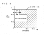
- Fig. 2 shows the map for the warm state of engine 10
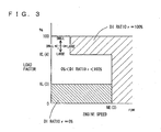
- Fig. 3 shows the map for the cold state of engine 10.
- the fuel injection ratio of in-cylinder injector 110, or the DI ratio r is expressed in percentage.
- the DI ratio r is set for each operation region that is determined by the engine speed and the load factor of engine 10.
- "DI RATIO r ⁇ 0%”, “DI RATIO r ⁇ 100%” and "0% ⁇ DI RATIO r ⁇ 100%” each represent the region where fuel injection is carried out using both in-cylinder injector 110 and intake manifold injector 120.
- in-cylinder injector 110 contributes to an increase of output performance
- intake manifold injector 120 contributes to uniformity of the air-fuel mixture.
- the fuel injection ratio between in-cylinder injector 110 and intake manifold injector 120 is defined as the DI ratio r, individually in the maps for the warm state and the cold state of the engine.
- the maps are configured to indicate different control regions of in-cylinder injector 110 and intake manifold injector 120 as the temperature of engine 10 changes.
- the map for the warm state shown in Fig. 2 is selected; otherwise, the map for the cold state shown in Fig. 3 is selected.
- One or both of in-cylinder injector 110 and intake manifold injector 120 are controlled based on the selected map and according to the engine speed and the load factor of engine 10 (which corresponds to a second invention).
- NE(1) is set to 2500 rpm to 2700 rpm
- KL(1) is set to 30% to 50%
- KL(2) is set to 60% to 90%
- NE(3) is set to 2900 rpm to 3100 rpm. That is, NE(1) ⁇ NE(3).
- NE(2) in Fig. 2 as well as KL(3) and KL(4) in Fig. 3 are also set as appropriate.
- NE(3) of the map for the cold state shown in Fig. 3 is greater than NE(1) of the map for the warm state shown in Fig. 2 .
- the control region of intake manifold injector 120 is expanded to include the region of higher engine speed (which corresponds to a third invention). That is, when engine 10 is cold, deposits are unlikely to accumulate in the injection hole of in-cylinder injector 110 (even if the fuel is not injected from in-cylinder injector 110).
- the region where the fuel injection is to be carried out using intake manifold injector 120 can be expanded, to thereby improve homogeneity.
- the fuel injection ratio of in-cylinder injector 110 is increased as the engine speed increases where such a problem is unlikely to occur (which corresponds to the first invention), whereas the fuel injection ratio of in-cylinder injector 110 is decreased as the engine load increases where such a problem is likely to occur (which corresponds to a fourth invention).
- These changes in the fuel injection ratio of in-cylinder injector 110, or, the DI ratio r, are shown by crisscross arrows in Figs. 2 and 3 . In this manner, variation in output torque of the engine attributable to the unstable combustion can be suppressed.
- these measures are approximately equivalent to the measures to decrease the fuel injection ratio of in-cylinder injector 110 as the state of the engine moves toward the predetermined low speed region, or to increase the fuel injection ratio of in-cylinder injector 110 as the engine state moves toward the predetermined low load region. Further, except for the relevant region (indicated by the crisscross arrows in Figs. 2 and 3 ), in the region where fuel injection is carried out using only in-cylinder injector 110 (on the high speed side and on the low load side), a homogeneous air-fuel mixture is readily obtained even when the fuel injection is carried out using only in-cylinder injector 110.
- the fuel injected from in-cylinder injector 110 is atomized within the combustion chamber involving latent heat of vaporization (by absorbing heat from the combustion chamber). Accordingly, the temperature of the air-fuel mixture is decreased at the compression side, and thus, the antiknock performance improves. Further, with the temperature of the combustion chamber decreased, intake efficiency improves, leading to high power output.
- in-cylinder injector 110 In the map for the warm state in Fig. 2 , fuel injection is also carried out using only in-cylinder injector 110 when the load factor is KL(1) or less. This shows that in-cylinder injector 110 alone is used in a predetermined low load region when the temperature of engine 10 is high (which corresponds to a six invention). When engine 10 is in the warm state, deposits are likely to accumulate in the injection hole of in-cylinder injector 110. However, when fuel injection is carried out using in-cylinder injector 110, the temperature of the injection hole can be lowered, whereby accumulation of deposits is prevented. Further, clogging of in-cylinder injector 110 may be prevented while ensuring a minimum fuel injection quantity thereof. Thus, in-cylinder injector 110 alone is used in the relevant region.
- in-cylinder injector 110 is controlled to carry out stratified charge combustion (which corresponds to a fifth invention).
- stratified charge combustion which corresponds to a fifth invention.
- homogeneous combustion is achieved by setting the fuel injection timing of in-cylinder injector 110 in the intake stroke, while stratified charge combustion is achieved by setting it in the compression stroke. That is, when the fuel injection timing of in-cylinder injector 110 is set in the compression stroke, a rich air-fuel mixture can be located locally around the spark plug, so that a lean air-fuel mixture in the combustion chamber as a whole is ignited to realize the stratified charge combustion. Even if the fuel injection timing of in-cylinder injector 110 is set in the intake stroke, stratified charge combustion can be realized if it is possible to locate a rich air-fuel mixture locally around the spark plug.
- the stratified charge combustion includes both the stratified charge combustion and semi-stratified charge combustion.
- intake manifold injector 120 injects fuel in the intake stroke to generate a lean and homogeneous air-fuel mixture in the whole combustion chamber, and then in-cylinder injector 110 injects fuel in the compression stroke to generate a rich air-fuel mixture around the spark plug, so as to improve the combustion state.
- Such semi-stratified charge combustion is preferable in the catalyst warm-up operation for the following reasons. In the catalyst warm-up operation, it is necessary to considerably retard the ignition timing and maintain favorable combustion state (idling state) so as to cause a high-temperature combustion gas to reach the catalyst. Further, a certain quantity of fuel needs to be supplied.
- the quantity of the fuel will be insufficient.
- the retarded amount for the purpose of maintaining favorable combustion is small compared to the case of stratified charge combustion.
- the above-described semi-stratified charge combustion is preferably employed in the catalyst warm-up operation, although either of stratified charge combustion and semi-stratified charge combustion may be employed.
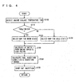
- FIG. 4 a control structure of a program that is executed by engine ECU 300 implementing the control apparatus according to an embodiment of the present invention will be described.
- step (hereinafter, abbreviated as "S") 100 engine ECU 300 detects an engine coolant temperature THW based on data input from coolant temperature sensor 380.
- step 110 engine ECU 300 determines whether the detected engine coolant temperature THW is equal to or higher than a predetermined temperature threshold value THW(TH), which may be set to 70°C to 90°C, for example. If engine coolant temperature THW is equal to or higher than temperature threshold value THW(TH) (YES in S110), the process goes to S120. If not (NO in S110), the process goes to S130.
- a predetermined temperature threshold value THW(TH) which may be set to 70°C to 90°C, for example.
- engine ECU 300 selects the map for the warm state ( Fig. 2 ).
- engine ECU 300 selects the map for the cold state ( Fig. 3 ).
- engine ECU 300 calculates DI ratio r from the engine speed and the load factor of engine 10, based on the selected map.
- the engine speed of engine 10 is calculated based on the data input from engine speed sensor 460, and the load factor is calculated based on the data input from accelerator pedal position sensor 440 as well as the running state of the vehicle.
- engine ECU 300 controls in-cylinder injector 110 and intake manifold injector 120 based on the fuel injection quantity(ies) and the injection timing(s) calculated, to effect the fuel injection.
- engine ECU 300 controls engine 10 assuming that it is in the abnormal operation state that does not correspond to any of Figs. 2-4 .
- the catalyst is inactive, and emission of the exhaust gas into the atmosphere should be avoided.
- the engine enters a stratified charge combustion mode, and the fuel is injected from in-cylinder injector 110 to realize stratified charge combustion.
- the stratified charge combustion in this case lasts for from some seconds to some tens of seconds.
- stratified charge combustion herein includes both the stratified charge combustion and the semi-stratified charge combustion, as described above.
- the temperature of engine 10 increases after start-up thereof.
- the map for the cold state ( Fig. 3 ) is selected until the temperature of engine 10 (engine coolant temperature THW) reaches a predetermined temperature threshold value (of 80°C, for example) (NO in S110).
- the fuel injection ratio of in-cylinder injector 100 i.e., DI ratio r
- DI ratio r is calculated based on the selected map for the cold state ( Fig. 3 ) and the engine speed and the load factor of engine 10.
- the DI ratio r obtained is used to calculate the fuel injection quantity(ies) and the injection timing(s) (S150), and based thereon, in-cylinder injector 110 and intake manifold injector 120 are controlled to carry out the fuel injection. In this state, homogeneous combustion is effected in any region shown in Fig. 3 .
- the fuel injection ratio of in-cylinder injector 110 i.e., DI ratio r
- DI ratio r is calculated based on the selected map for the warm state ( Fig. 2 ) and the engine speed and the load factor of engine 10. Based on the calculated DI ratio r, the fuel injection quantity(ies) and the injection timing(s) are calculated (S150), and based thereon, in-cylinder injector 110 and intake manifold injector 120 are controlled to carry out the fuel injection. In this state, homogeneous combustion is effected in any region shown in Fig. 2 .
- the fuel injection ratio therebetween is controlled based on the maps that are separately prepared, e.g., for the warm state and the cold state of the internal combustion engine and are set according to the engine speed and the load factor of the engine.
- the control of the fuel injection ratio is carried out based on the maps such that homogeneous combustion is realized over the entire region. Accordingly, the conventional problem associated with control of switching between the stratified charge combustion and the homogeneous combustion, as well as the conventional problem associated with control of the homogeneous combustion in the case of a direct injection engine, can be solved.
- in-cylinder injector 110 is timed to inject fuel at the compression stroke for the following reason, although in engine 10 described above, the fuel injection timing of in-cylinder injector 110 is set in the intake stroke in a basic region corresponding to the almost entire region (herein, the basic region refers to the region other than the region where semi-stratified charge combustion is conducted by causing intake manifold injector 120 to inject the fuel in the intake stroke and causing in-cylinder injector 110 to inject the fuel in the compression stroke, which is conducted only in the catalyst warm-up state).
- the fuel injection timing of in-cylinder injector 110 may be set temporarily in the compression stroke for the purpose of stabilizing combustion, for the following reasons.
- the air-fuel mixture is cooled by the injected fuel while the temperature in the cylinder is relatively high. This improves the cooling effect and, hence, the antiknock performance. Further, when the fuel injection timing of in-cylinder injector 110 is set in the compression stroke, the time from the fuel injection to the ignition is short, which ensures strong penetration of the injected fuel, so that the combustion rate increases. The improvement in antiknock performance and the increase in combustion rate can prevent variation in combustion, and thus, combustion stability is improved.
Landscapes
- Engineering & Computer Science (AREA)
- Chemical & Material Sciences (AREA)
- Combustion & Propulsion (AREA)
- Mechanical Engineering (AREA)
- General Engineering & Computer Science (AREA)
- Electrical Control Of Air Or Fuel Supplied To Internal-Combustion Engine (AREA)
- Combined Controls Of Internal Combustion Engines (AREA)
- Fuel-Injection Apparatus (AREA)
Description
- The present invention relates to a control apparatus for an internal combustion engine having a first fuel injection mechanism (an in-cylinder injector) for injecting a fuel into a cylinder and a second fuel injection mechanism (an intake manifold injector) for injecting a fuel into an intake manifold or an intake port, and relates particularly to a technique for determining a fuel injection ratio between the first and second fuel injection mechanisms.
- An internal combustion engine having a first fuel injection valve (an intake manifold injector in the background art) for injecting a fuel into an intake manifold of the engine and a second fuel injection valve (an in-cylinder injector in the background art) for always injecting a fuel into a combustion chamber of the engine, and configured to stop fuel injection from the first fuel injection valve (the intake manifold injector) when the engine load is lower than a preset load and to cause fuel injection from the first fuel injection valve (the intake manifold injector) when the engine load is higher than the set load, is known.
- In such an internal combustion engine, one configured to switch between stratified charge combustion and homogeneous combustion in accordance with its operation state is known. In the stratified charge combustion, the fuel is injected from the in-cylinder injector during a compression stroke to form a stratified air-fuel mixture locally around a spark plug, for lean combustion of the fuel. In the homogeneous combustion, the fuel is diffused in the combustion chamber to form a homogeneous air-fuel mixture, for combustion of the fuel.
- Japanese Patent Laying-Open No.
JP 2001-020837 A - According to this fuel injection control apparatus for the engine, the stratified charge combustion is carried out using only the main fuel injection valve directly injecting the fuel into the combustion chamber, while the homogeneous combustion is carried out using both the main fuel injection valve and the secondary fuel injection valve (or using only the secondary fuel injection valve in some cases). This can keep the capacity of the main fuel injection valve small, even in the case of an engine of high power. Linearity in injection duration/injection quantity characteristic of the main fuel injection valve in a low-load region such as during idling is improved, which in turn improves accuracy in control of the fuel injection quantity. Accordingly, it is possible to maintain favorable stratified charge combustion, and thus to improve stability of the low-load operation such as idling. In the homogeneous combustion, both the main and secondary fuel injection valves are employed, so that the benefit of the direct fuel injection and the benefit of the intake port injection are both enjoyed. Accordingly, favorable homogeneous combustion can also be maintained.
- In the fuel injection control apparatus for the engine disclosed in Japanese Patent Laying-Open No.
JP 2001-020837 A - Based on the foregoing, a direct injection engine has been developed which has only an in-cylinder injector to carry out homogeneous combustion over the entire region, with no stratified charge combustion conducted, and thus does not need control for switching between the stratified charge combustion and the homogeneous combustion and does not require an expensive lean NOx catalyst.
- In such a direct injection engine, however, the homogeneous combustion is carried out over the entire region using only the in-cylinder injector. This may lead to insufficient homogeneity and large torque fluctuations in the low-speed and high-load state of the engine. Japanese Patent Laying-Open No.
JP 2001-020837 A - Document
EP 943 793 A2 - Document
WO 2006/049230 A1 , which is prior art under Art. 54(3) EPC, discloses an engine ECU which executes a program including the steps of: determining presence of abnormality in a low-pressure fuel system; ceasing an intake manifold injector when determination is made of abnormality in the low-pressure fuel system; increasing the target purge rate when the engine operation state attains an injection partaking state between an in-cylinder injector and an intake manifold injector; reducing the VVT overlap; and retarding the ignition timing. - An object of the present invention is to provide a control apparatus for an internal combustion engine conducting fuel injection using one or both of a first fuel injection mechanism for injecting a fuel into a cylinder and a second fuel injection mechanism for injecting a fuel into an intake manifold, capable of solving the problem associated with a combination of stratified charge combustion and homogeneous combustion, and also capable of solving the problem associated with homogeneous combustion in the case of a direct injection engine.
- A control apparatus according to the present invention controls an internal combustion engine. Said internal combustion engine comprising: a first fuel injection mechanism for injecting a fuel into a cylinder and a second fuel injection mechanism for injecting a fuel into an intake port and/or an intake manifold. The control apparatus includes a determination unit for determining whether the internal combustion engine is in a normal operation state or an abnormal operation state, wherein the abnormal operation state is an operation state during catalyst warm-up operation upon idling, and a control unit for controlling the first and second fuel injection mechanisms based on information associated with an operation state of the internal combustion engine such that when it is determined that the internal combustion engine is in the normal operation state, solely homogeneous combustion is carried out over the full range of engine operation, and, when it is determined that said internal combustion engine is in said abnormal operation state, semi-stratified charge combustion is carried out during catalyst warm-up operation upon idling, wherein said information is information that said first fuel injection mechanism has a fuel injection ratio that is defined as a ratio of quantity of the fuel injected from said first fuel injection mechanism to the total quantity of fuel injected, increased as an engine speed increases in low-speed and high-load region.
- According to this invention, when the first fuel injection mechanism (for example, an in-cylinder injector) and the second fuel injection mechanism (for example, an intake manifold injector) are both used for fuel injection, the fuel injection ratio between the in cylinder injector and the intake manifold injector is controlled based on an operation state of the internal combustion engine (determined, e.g., by the engine speed and the load thereof) that is set separately for the warm state and the cold state of the internal combustion engine, for example. This can realize homogeneous combustion over the entire region, so that the conventional problem is solved. It is noted that an example of an operation state other than the normal operation state may be a catalyst warm-up operation during idling. In particular, in the low-speed and high-load region, mixing of an air-fuel mixture formed by the fuel injected from the in-cylinder injector is poor, and such inhomogeneous air-fuel mixture within the combustion chamber may lead to unstable combustion. Accordingly in the present invention the fuel injection ratio of the in-cylinder injector is increased as the engine speed increases where such a problem is unlikely to occur. As a result, it is possible to provide a control apparatus for an internal combustion engine where fuel injection is carried out using one or both of the first fuel injection mechanism for injecting the fuel into the cylinder and the second fuel injection mechanism for injecting the fuel into the intake manifold, which can solve the problem associated with the combination of the stratified charge combustion and the homogeneous combustion as well as the problem associated with the homogeneous combustion in the case of a direct injection engine. It is noted that the present invention is generally equivalent to decreasing the fuel injection ratio of the first fuel injection mechanism as the state of the engine moves toward a predetermined low speed region.
- Preferably, the information is set such that control regions of the first and second fuel injection mechanisms change as a temperature of the internal combustion engine changes. In this case, the control apparatus further includes a detection unit for detecting the temperature of the internal combustion engine, and the control unit controls the fuel injection mechanisms based on the detected temperature and the information.
- According to this invention, the fuel injection ratio between the in-cylinder injector and the intake manifold injector is set based on the temperature of the internal combustion engine (separately for the warm state and the cold state of the internal combustion engine, for example), or the fuel injection ratio therebetween is set using the temperature of the internal combustion engine as a parameter. Thus, by making the regions of the fuel supply injectors of different characteristics variable in accordance with the temperature of the internal combustion engine, it is possible to provide a control apparatus for an internal combustion engine of high performance having dual injectors.
- More preferably, the information is set such that the control region of the second fuel injection mechanism is expanded to include a region of higher engine speed as the temperature of the internal combustion engine is lower.
- According to this invention, accumulation of deposits in the in-cylinder injector is further restricted as the temperature of the internal combustion engine is lower. It is thus possible to secure a large injection region for the intake manifold injector (including the region where both the intake manifold injector and the in-cylinder injector are used), which can improve homogeneity of the air-fuel mixture.
- More preferably, the information indicates that the first fuel injection mechanism has a fuel injection ratio decreased as the engine's load increases in said low-speed and high load region.
- According to the present invention, in the low-speed and high-load region, mixing of an air-fuel mixture formed by the fuel injected from the in-cylinder injector is poor, and such inhomogeneous air-fuel mixture within the combustion chamber may lead to unstable combustion. Accordingly in the present invention the fuel injection ratio of the in-cylinder injector is decreased as the engine's load shifts to a high-load region where such a problem occurs. This can reduce the variation of a torque output from the engine that is attributed to unstable combustion. Note that the present invention is generally equivalent to increasing the fuel injection ratio of the first fuel injection mechanism as the engine's load shifts to a predetermined low-load region.
- More preferably, the determination unit determines that the internal combustion engine is in an abnormal operation state during a catalyst warm-up operation upon idling. Then, the control unit further includes an abnormal operation state controller controlling the first fuel injection mechanism to carry out stratified charge combustion in the abnormal operation state.
- More preferably, the information is set such that the first fuel injection mechanism alone is used in a predetermined, low engine load region when a temperature of the internal combustion engine is high.
- In the warm state of the internal combustion engine, the temperature at the injection hole of the in-cylinder injector is high, and deposits are likely to accumulate in the injection hole. According to the invention, however, injecting the fuel using the in-cylinder injector can lower the temperature at the injection hole, thereby preventing accumulation of the deposits therein. Further, the minimum fuel injection quantity of the in-cylinder injection can be guaranteed while preventing clogging of the in-cylinder injector. Accordingly, homogeneous combustion is realized in the relevant region using the in-cylinder injector.
- More preferably, the information is set such that the second fuel injection mechanism alone is used in a predetermined, low engine load region when the temperature of the internal combustion engine is low.
- In the cold state of the internal combustion engine, if its load is low, the quantity of the intake air is small, and the fuel is unlikely to be atomized. In such a region, it is difficult to ensure good combustion with the fuel injection using the in-cylinder injector. Further, particularly in the low-load and low-speed region, high output using the in-cylinder injector is unnecessary. Therefore, according to the invention, instead of the in-cylinder injector, the intake manifold injector solely is used for fuel injection in the relevant region, which can improve the homogeneity of the air-fuel mixture.
- According to this invention, the fuel injection ratio between the in-cylinder injector and the intake manifold injector is determined based on the engine speed and the load factor of the internal combustion engine, and in a normal operation state, homogeneous combustion is realized with any engine speed and any load factor.
- More preferably, the first fuel injection mechanism is an in-cylinder injector, and the second fuel injection mechanism is an intake manifold injector.
- According to this invention, it is possible to provide a control apparatus for the internal combustion engine in which fuel injection is carried out using the in-cylinder injector as the first fuel injection mechanism and the intake manifold injector as the second fuel injection mechanism that are separately provided, capable of solving the problem associated with the combination of the stratified charge combustion and the homogeneous combustion as well as the problem associated with the homogeneous combustion in the case of a direct injection engine.
-
-
Fig. 1 is a schematic configuration diagram of an engine system controlled by a control apparatus according to an embodiment of the present invention. -
Fig. 2 shows a DI ratio map for a warm state that is stored in an engine ECU implementing the control apparatus according to an embodiment of the present invention. -
Fig. 3 shows a DI ratio map for a cold state that is stored in the engine ECU implementing the control apparatus according to the embodiment of the present invention. -
Fig. 4 is a flowchart illustrating a control structure of a program that is executed by the engine ECU implementing the control apparatus according to the embodiment of the present invention. - Hereinafter, embodiments of the present invention will be described with reference to the drawings. In the following description, the same parts have the same reference characters allotted and also have the same names and functions. Thus, detailed description thereof will not be repeated.
-
Fig. 1 is a schematic configuration diagram of an engine system that is controlled by an engine ECU (Electronic Control Unit) implementing the control apparatus for an internal combustion engine according to an embodiment of the present invention. InFig. 1 , an in-line 4-cylinder gasoline engine is shown, although the application of the present invention is not restricted to such an engine. - As shown in
Fig. 1 , theengine 10 includes fourcylinders 112, each connected via a correspondingintake manifold 20 to acommon surge tank 30.Surge tank 30 is connected via anintake duct 40 to anair cleaner 50. Anairflow meter 42 is arranged inintake duct 40, and athrottle valve 70 driven by anelectric motor 60 is also arranged inintake duct 40.Throttle valve 70 has its degree of opening controlled based on an output signal of anengine ECU 300, independently from anaccelerator pedal 100. Eachcylinder 112 is connected to acommon exhaust manifold 80, which is connected to a three-waycatalytic converter 90. - Each
cylinder 112 is provided with an in-cylinder injector 110 for injecting fuel into the cylinder and anintake manifold injector 120 for injecting fuel into an intake port or/and an intake manifold.Injectors engine ECU 300. Further, in-cylinder injector 110 of each cylinder is connected to a commonfuel delivery pipe 130.Fuel delivery pipe 130 is connected to a high-pressure fuel pump 150 of an engine-driven type, via acheck valve 140 that allows a flow in the direction towardfuel delivery pipe 130. In the present embodiment, an internal combustion engine having two injectors separately provided is explained, although the present invention is not restricted to such an internal combustion engine. For example, the internal combustion engine may have one injector that can effect both in-cylinder injection and intake manifold injection. - As shown in
Fig. 1 , the discharge side of high-pressure fuel pump 150 is connected via anelectromagnetic spill valve 152 to the intake side of high-pressure fuel pump 150. As the degree of opening ofelectromagnetic spill valve 152 is smaller, the quantity of the fuel supplied from high-pressure fuel pump 150 intofuel delivery pipe 130 increases. Whenelectromagnetic spill valve 152 is fully open, the fuel supply from high-pressure fuel pump 150 tofuel delivery pipe 130 is stopped.Electromagnetic spill valve 152 is controlled based on an output signal of engine,ECU 300. - Each
intake manifold injector 120 is connected to a commonfuel delivery pipe 160 on a low pressure side.Fuel delivery pipe 160 and high-pressure fuel pump 150 are connected via a commonfuel pressure regulator 170 to a low-pressure fuel pump 180 of an electric motor-driven type. Further, low-pressure fuel pump 180 is connected via afuel filter 190 to afuel tank 200.Fuel pressure regulator 170 is configured to return a part of the fuel discharged from low-pressure fuel pump 180 back tofuel tank 200 when the pressure of the fuel discharged from low-pressure fuel pump 180 is higher than a preset fuel pressure. This prevents both the pressure of the fuel supplied tointake manifold injector 120 and the pressure of the fuel supplied to high-pressure fuel pump 150 from becoming higher than the above-described preset fuel pressure. -
Engine ECU 300 is implemented with a digital computer, and includes a ROM (Read Only Memory) 320, a RAM (Random Access Memory) 330, a CPU (Central Processing Unit) 340, aninput port 350, and anoutput port 360, which are connected to each other via abidirectional bus 310. -
Airflow meter 42 generates an output voltage that is proportional to an intake air quantity, and the output voltage is input via an A/D converter 370 to inputport 350. Acoolant temperature sensor 380 is attached toengine 10, and generates an output voltage proportional to a coolant temperature of the engine, which is input via an A/D converter 390 to inputport 350. - A
fuel pressure sensor 400 is attached tofuel delivery pipe 130, and generates an output voltage proportional to a fuel pressure withinfuel delivery pipe 130, which is input via an A/D converter 410 to inputport 350. An air-fuel ratio sensor 420 is attached to anexhaust manifold 80 located upstream of three-waycatalytic converter 90. Air-fuel ratio sensor 420 generates an output voltage proportional to an oxygen concentration within the exhaust gas, which is input via an A/D converter 430 to inputport 350. - Air-
fuel ratio sensor 420 of the engine system of the present embodiment is a full-range air-fuel ratio sensor (linear air-fuel ratio sensor) that generates an output voltage proportional to the air-fuel ratio of the air-fuel mixture burned inengine 10. As air-fuel ratio sensor 420, an O2 sensor may be employed, which detects, in an on/off manner, whether the air-fuel ratio of the air-fuel mixture burned inengine 10 is rich or lean with respect to a theoretical air-fuel ratio. -
Accelerator pedal 100 is connected with an acceleratorpedal position sensor 440 that generates an output voltage proportional to the degree of press down ofaccelerator pedal 100, which is input via an A/D converter 450 to inputport 350. Further, anengine speed sensor 460 generating an output pulse representing the engine speed is connected to inputport 350.ROM 320 ofengine ECU 300 prestores, in the form of a map, values of fuel injection quantity that are set in association with operation states based on the engine load factor and the engine speed obtained by the above-described acceleratorpedal position sensor 440 andengine speed sensor 460, and correction values thereof set based on the engine coolant temperature. - Referring to
Figs. 2 and3 , maps each indicating a fuel injection ratio between in-cylinder injector 110 andintake manifold injector 120, identified as information associated with an operation state ofengine 10, will now be described. Herein, the fuel injection ratio between the two injectors will also be expressed as a ratio of the quantity of the fuel injected from in-cylinder injector 110 to the total quantity of the fuel injected, which is referred to as the "fuel injection ratio of in-cylinder injector 110", or, a "DI (Direct Injection) ratio (r)". The maps are stored inROM 320 ofengine ECU 300.Fig. 2 shows the map for the warm state ofengine 10, andFig. 3 shows the map for the cold state ofengine 10. - In the maps shown in
Figs. 2 and3 , with the horizontal axis representing an engine speed ofengine 10 and the vertical axis representing a load factor, the fuel injection ratio of in-cylinder injector 110, or the DI ratio r, is expressed in percentage. - As shown in
Figs. 2 and3 , the DI ratio r is set for each operation region that is determined by the engine speed and the load factor ofengine 10. "DI RATIO r = 100%" represents the region where fuel injection is carried out using only in-cylinder injector 110, and "DI RATIO r = 0%" represents the region where fuel injection is carried out using onlyintake manifold injector 120. "DI RATIO r ≠ 0%", "DI RATIO r ≠ 100%" and "0% < DI RATIO r < 100%" each represent the region where fuel injection is carried out using both in-cylinder injector 110 andintake manifold injector 120. Generally, in-cylinder injector 110 contributes to an increase of output performance, whileintake manifold injector 120 contributes to uniformity of the air-fuel mixture. These two kinds of injectors having different characteristics are appropriately selected depending on the engine speed and the load factor ofengine 10, so that only homogeneous combustion is conducted in the normal operation state of engine 10 (other than the abnormal operation state such as a catalyst warm-up state during idling, for example) (which corresponds to a first invention). - Further, as shown in
Figs. 2 and3 , the fuel injection ratio between in-cylinder injector 110 andintake manifold injector 120 is defined as the DI ratio r, individually in the maps for the warm state and the cold state of the engine. The maps are configured to indicate different control regions of in-cylinder injector 110 andintake manifold injector 120 as the temperature ofengine 10 changes. When the temperature ofengine 10 detected is equal to or higher than a predetermined temperature threshold value, the map for the warm state shown inFig. 2 is selected; otherwise, the map for the cold state shown inFig. 3 is selected. One or both of in-cylinder injector 110 andintake manifold injector 120 are controlled based on the selected map and according to the engine speed and the load factor of engine 10 (which corresponds to a second invention). - The engine speed and the load factor of
engine 10 set inFigs. 2 and3 will now be described. InFig. 2 , NE(1) is set to 2500 rpm to 2700 rpm, KL(1) is set to 30% to 50%, and KL(2) is set to 60% to 90%. InFig. 3 , NE(3) is set to 2900 rpm to 3100 rpm. That is, NE(1) < NE(3). NE(2) inFig. 2 as well as KL(3) and KL(4) inFig. 3 are also set as appropriate. - When comparing
Fig. 2 andFig. 3 , NE(3) of the map for the cold state shown inFig. 3 is greater than NE(1) of the map for the warm state shown inFig. 2 . This shows that, as the temperature ofengine 10 is lower, the control region ofintake manifold injector 120 is expanded to include the region of higher engine speed (which corresponds to a third invention). That is, whenengine 10 is cold, deposits are unlikely to accumulate in the injection hole of in-cylinder injector 110 (even if the fuel is not injected from in-cylinder injector 110). Thus, the region where the fuel injection is to be carried out usingintake manifold injector 120 can be expanded, to thereby improve homogeneity. - When comparing
Fig. 2 andFig. 3 , "DI RATIO r = 100%" holds in the region where the engine speed ofengine 10 is equal to or higher than NE(1) in the map for the warm state, and in the region where the engine speed is NE(3) or higher in the map for the cold state. Further, except for the low-speed region, "DI RATIO r = 100%" holds in the region where the load factor is KL(2) or greater in the map for the warm state, and in the region where the load factor is KL(4) or greater in the map for the cold state. This means that fuel injection is carried out using only in-cylinder injector 110 in the region where the engine speed is at a predetermined high level, and that fuel injection is often carried out using only in-cylinder injector 110 in the region where the engine load is at a predetermined high level. However, in the low-speed and high-load region, mixing of an air-fuel mixture formed by the fuel injected from in-cylinder injector 110 is poor, and such inhomogeneous air-fuel mixture within the combustion chamber may lead to unstable combustion. Accordingly, the fuel injection ratio of in-cylinder injector 110 is increased as the engine speed increases where such a problem is unlikely to occur (which corresponds to the first invention), whereas the fuel injection ratio of in-cylinder injector 110 is decreased as the engine load increases where such a problem is likely to occur (which corresponds to a fourth invention). These changes in the fuel injection ratio of in-cylinder injector 110, or, the DI ratio r, are shown by crisscross arrows inFigs. 2 and3 . In this manner, variation in output torque of the engine attributable to the unstable combustion can be suppressed. It is noted that these measures are approximately equivalent to the measures to decrease the fuel injection ratio of in-cylinder injector 110 as the state of the engine moves toward the predetermined low speed region, or to increase the fuel injection ratio of in-cylinder injector 110 as the engine state moves toward the predetermined low load region. Further, except for the relevant region (indicated by the crisscross arrows inFigs. 2 and3 ), in the region where fuel injection is carried out using only in-cylinder injector 110 (on the high speed side and on the low load side), a homogeneous air-fuel mixture is readily obtained even when the fuel injection is carried out using only in-cylinder injector 110. In this case, the fuel injected from in-cylinder injector 110 is atomized within the combustion chamber involving latent heat of vaporization (by absorbing heat from the combustion chamber). Accordingly, the temperature of the air-fuel mixture is decreased at the compression side, and thus, the antiknock performance improves. Further, with the temperature of the combustion chamber decreased, intake efficiency improves, leading to high power output. - In the map for the warm state in
Fig. 2 , fuel injection is also carried out using only in-cylinder injector 110 when the load factor is KL(1) or less. This shows that in-cylinder injector 110 alone is used in a predetermined low load region when the temperature ofengine 10 is high (which corresponds to a six invention). Whenengine 10 is in the warm state, deposits are likely to accumulate in the injection hole of in-cylinder injector 110. However, when fuel injection is carried out using in-cylinder injector 110, the temperature of the injection hole can be lowered, whereby accumulation of deposits is prevented. Further, clogging of in-cylinder injector 110 may be prevented while ensuring a minimum fuel injection quantity thereof. Thus, in-cylinder injector 110 alone is used in the relevant region. - When comparing
Fig. 2 andFig. 3 , there is a region of "DI RATIO r = 0%" only in the map for the cold state inFig. 3 . This shows that fuel injection is carried out using onlyintake manifold injector 120 in a predetermined low load region (KL(3) or less) when the temperature ofengine 10 is low (which corresponds to a seventh invention). Whenengine 10 is cold and low in load and the intake air quantity is small, atomization of the fuel is unlikely to occur. In such a region, it is difficult to ensure favorable combustion with the fuel injection from in-cylinder injector 110. Further, particularly in the low-load and low-speed region, high power output using in-cylinder injector 110 is unnecessary. Accordingly, fuel injection is carried out usingintake manifold injector 120 alone, rather than using in-cylinder injector 110, in the relevant region. - Further, in an operation other than the normal operation, i.e., in the catalyst warm-up state at idle of engine 10 (abnormal operation state), in-
cylinder injector 110 is controlled to carry out stratified charge combustion (which corresponds to a fifth invention). By causing the stratified charge combustion during the catalyst warm-up operation, warming up of the catalyst is promoted, and exhaust emission is thus improved. - In
engine 10, homogeneous combustion is achieved by setting the fuel injection timing of in-cylinder injector 110 in the intake stroke, while stratified charge combustion is achieved by setting it in the compression stroke. That is, when the fuel injection timing of in-cylinder injector 110 is set in the compression stroke, a rich air-fuel mixture can be located locally around the spark plug, so that a lean air-fuel mixture in the combustion chamber as a whole is ignited to realize the stratified charge combustion. Even if the fuel injection timing of in-cylinder injector 110 is set in the intake stroke, stratified charge combustion can be realized if it is possible to locate a rich air-fuel mixture locally around the spark plug. - As used herein, the stratified charge combustion includes both the stratified charge combustion and semi-stratified charge combustion. In the semi-stratified charge combustion,
intake manifold injector 120 injects fuel in the intake stroke to generate a lean and homogeneous air-fuel mixture in the whole combustion chamber, and then in-cylinder injector 110 injects fuel in the compression stroke to generate a rich air-fuel mixture around the spark plug, so as to improve the combustion state. Such semi-stratified charge combustion is preferable in the catalyst warm-up operation for the following reasons. In the catalyst warm-up operation, it is necessary to considerably retard the ignition timing and maintain favorable combustion state (idling state) so as to cause a high-temperature combustion gas to reach the catalyst. Further, a certain quantity of fuel needs to be supplied. If the stratified charge combustion is employed to satisfy these requirements, the quantity of the fuel will be insufficient. With the homogeneous combustion, the retarded amount for the purpose of maintaining favorable combustion is small compared to the case of stratified charge combustion. For these reasons, the above-described semi-stratified charge combustion is preferably employed in the catalyst warm-up operation, although either of stratified charge combustion and semi-stratified charge combustion may be employed. - Referring to
Fig. 4 , a control structure of a program that is executed byengine ECU 300 implementing the control apparatus according to an embodiment of the present invention will be described. - In step (hereinafter, abbreviated as "S") 100,
engine ECU 300 detects an engine coolant temperature THW based on data input fromcoolant temperature sensor 380. In S110,engine ECU 300 determines whether the detected engine coolant temperature THW is equal to or higher than a predetermined temperature threshold value THW(TH), which may be set to 70°C to 90°C, for example. If engine coolant temperature THW is equal to or higher than temperature threshold value THW(TH) (YES in S110), the process goes to S120. If not (NO in S110), the process goes to S130. - In S120,
engine ECU 300 selects the map for the warm state (Fig. 2 ). - In S130,
engine ECU 300 selects the map for the cold state (Fig. 3 ). - In S140,
engine ECU 300 calculates DI ratio r from the engine speed and the load factor ofengine 10, based on the selected map. The engine speed ofengine 10 is calculated based on the data input fromengine speed sensor 460, and the load factor is calculated based on the data input from acceleratorpedal position sensor 440 as well as the running state of the vehicle. - In S150,
engine ECU 300 calculates the fuel injection quantity and the injection timing of in-cylinder injector 110 if DI ratio r = 100%, calculates the fuel injection quantity and the injection timing ofintake manifold injector 120 if DI ratio r = 0%, or calculates the fuel injection quantities and the injection timings of in-cylinder injector 110 andintake manifold injector 120 if DI ratio r ≠ 0% or DI ratio r ≠ 100% (0% < DI ratio r < 100%). - In S160,
engine ECU 300 controls in-cylinder injector 110 andintake manifold injector 120 based on the fuel injection quantity(ies) and the injection timing(s) calculated, to effect the fuel injection. - An operation of
engine 10 controlled byengine ECU 300 implementing the control apparatus for an internal combustion engine of the present embodiment based on the above-described structure and flowchart will now be described. - For example, immediately after start-up of
engine 10 whereengine 10 is cold,engine ECU 300controls engine 10 assuming that it is in the abnormal operation state that does not correspond to any ofFigs. 2-4 . In this state, the catalyst is inactive, and emission of the exhaust gas into the atmosphere should be avoided. Thus, the engine enters a stratified charge combustion mode, and the fuel is injected from in-cylinder injector 110 to realize stratified charge combustion. The stratified charge combustion in this case lasts for from some seconds to some tens of seconds. - It is noted that the stratified charge combustion herein includes both the stratified charge combustion and the semi-stratified charge combustion, as described above.
- The temperature of
engine 10 increases after start-up thereof. The map for the cold state (Fig. 3 ) is selected until the temperature of engine 10 (engine coolant temperature THW) reaches a predetermined temperature threshold value (of 80°C, for example) (NO in S110). - The fuel injection ratio of in-
cylinder injector 100, i.e., DI ratio r, is calculated based on the selected map for the cold state (Fig. 3 ) and the engine speed and the load factor ofengine 10. The DI ratio r obtained is used to calculate the fuel injection quantity(ies) and the injection timing(s) (S150), and based thereon, in-cylinder injector 110 andintake manifold injector 120 are controlled to carry out the fuel injection. In this state, homogeneous combustion is effected in any region shown inFig. 3 . - With a further increase, when temperature of engine 10 (engine coolant temperature THW) becomes equal to or higher than the predetermined temperature threshold value (of 80°C, for example) (YES in S110), the map for the warm state (
Fig. 2 ) is selected. - The fuel injection ratio of in-
cylinder injector 110, i.e., DI ratio r, is calculated based on the selected map for the warm state (Fig. 2 ) and the engine speed and the load factor ofengine 10. Based on the calculated DI ratio r, the fuel injection quantity(ies) and the injection timing(s) are calculated (S150), and based thereon, in-cylinder injector 110 andintake manifold injector 120 are controlled to carry out the fuel injection. In this state, homogeneous combustion is effected in any region shown inFig. 2 . - As described above, in the engine controlled by the engine ECU of the present embodiment, when the fuel injection is being carried out using both the in-cylinder injector and the intake manifold injector, the fuel injection ratio therebetween is controlled based on the maps that are separately prepared, e.g., for the warm state and the cold state of the internal combustion engine and are set according to the engine speed and the load factor of the engine. At this time, the control of the fuel injection ratio is carried out based on the maps such that homogeneous combustion is realized over the entire region. Accordingly, the conventional problem associated with control of switching between the stratified charge combustion and the homogeneous combustion, as well as the conventional problem associated with control of the homogeneous combustion in the case of a direct injection engine, can be solved.
- Note that preferably in-
cylinder injector 110 is timed to inject fuel at the compression stroke for the following reason, although inengine 10 described above, the fuel injection timing of in-cylinder injector 110 is set in the intake stroke in a basic region corresponding to the almost entire region (herein, the basic region refers to the region other than the region where semi-stratified charge combustion is conducted by causingintake manifold injector 120 to inject the fuel in the intake stroke and causing in-cylinder injector 110 to inject the fuel in the compression stroke, which is conducted only in the catalyst warm-up state). The fuel injection timing of in-cylinder injector 110, however, may be set temporarily in the compression stroke for the purpose of stabilizing combustion, for the following reasons. - When the fuel injection timing of in-
cylinder injector 110 is set in the compression stroke, the air-fuel mixture is cooled by the injected fuel while the temperature in the cylinder is relatively high. This improves the cooling effect and, hence, the antiknock performance. Further, when the fuel injection timing of in-cylinder injector 110 is set in the compression stroke, the time from the fuel injection to the ignition is short, which ensures strong penetration of the injected fuel, so that the combustion rate increases. The improvement in antiknock performance and the increase in combustion rate can prevent variation in combustion, and thus, combustion stability is improved.
Claims (7)
- A control apparatus (300) for an internal combustion engine (10),
the internal combustion engine comprising:a first fuel injection mechanism (110) for injecting a fuel into a cylinder (112), anda second fuel injection mechanism (120) for injecting a fuel into an intake port and/or an intake manifold (20),the control apparatus comprising:a determination unit
for determining whether said internal combustion engine is in a normal operation state or an abnormal operation state,
the abnormal operation state being an operation state during catalyst warm-up operation upon idling; anda control unit
for controlling said first and second fuel injection mechanisms,
based on information associated with an operation state of said internal combustion engine,
such that,
when it is determined that said internal combustion engine is in said normal operation state,
solely homogeneous combustion is carried out over the full range of engine operation, and,
when it is determined that said internal combustion engine is in said abnormal operation state,
semi-stratified charge combustion is carried out during catalyst warm-up operation upon idling, wherein
said information is information that said first fuel injection mechanism has a fuel injection ratio, that is defined as a ratio of the quantity of the fuel injected from said first fuel injection mechanism to the total quantity of fuel injected, increased as an engine speed increases in a low-speed and high-load region. - The control apparatus for an internal combustion engine according to claim 1, wherein said information is set such that control regions of said first and second fuel injection mechanisms change as a temperature of said internal combustion engine changes,
the control apparatus further comprising:a detection unit for detecting the temperature of said internal combustion engine,said control unit controlling the fuel injection mechanisms based on said detected temperature and said information. - The control apparatus for an internal combustion engine according to claim 1, wherein said information is set such that a control region of said second fuel injection mechanism is expanded to include a region of higher engine speed as a temperature of said internal combustion engine is lower.
- The control apparatus for an internal combustion engine according to claim 1, wherein said information is information that said first fuel injection mechanism has a fuel injection ratio decreased as an engine load increases in said low-speed and high-load region.
- The control apparatus for an internal combustion engine according to claim 1, wherein said information is set such that said first fuel injection mechanism alone is used in a predetermined, low engine load region when a temperature of said internal combustion engine is high.
- The control apparatus for an internal combustion engine according to claim 1, wherein said information is set such that said second fuel injection mechanism alone is used in a predetermined, low engine load region when a temperature of said internal combustion engine is low.
- The control apparatus for an internal combustion engine according to any of claims 1-6, wherein
said first fuel injection mechanism is an in-cylinder injector, and
said second fuel injection mechanism is an intake manifold injector.
Applications Claiming Priority (2)
| Application Number | Priority Date | Filing Date | Title |
|---|---|---|---|
| JP2004328108A JP4487735B2 (en) | 2004-11-11 | 2004-11-11 | Control device for internal combustion engine |
| PCT/JP2005/020768 WO2006051924A1 (en) | 2004-11-11 | 2005-11-07 | Control apparatus for internal combustion engine |
Publications (2)
| Publication Number | Publication Date |
|---|---|
| EP1809881A1 EP1809881A1 (en) | 2007-07-25 |
| EP1809881B1 true EP1809881B1 (en) | 2015-05-13 |
Family
ID=35501289
Family Applications (1)
| Application Number | Title | Priority Date | Filing Date |
|---|---|---|---|
| EP20050803171 Not-in-force EP1809881B1 (en) | 2004-11-11 | 2005-11-07 | Control apparatus for internal combustion engine |
Country Status (11)
| Country | Link |
|---|---|
| US (1) | US7302928B2 (en) |
| EP (1) | EP1809881B1 (en) |
| JP (1) | JP4487735B2 (en) |
| KR (1) | KR100881877B1 (en) |
| CN (1) | CN100580240C (en) |
| AU (1) | AU2005302987B2 (en) |
| BR (1) | BRPI0517548A (en) |
| CA (1) | CA2576439C (en) |
| ES (1) | ES2537003T3 (en) |
| RU (1) | RU2349783C1 (en) |
| WO (1) | WO2006051924A1 (en) |
Families Citing this family (35)
| Publication number | Priority date | Publication date | Assignee | Title |
|---|---|---|---|---|
| JP4379251B2 (en) * | 2004-08-02 | 2009-12-09 | トヨタ自動車株式会社 | Control device and control method for internal combustion engine |
| JP2006258007A (en) * | 2005-03-18 | 2006-09-28 | Toyota Motor Corp | Control device of internal combustion engine |
| JP4333721B2 (en) * | 2006-09-22 | 2009-09-16 | トヨタ自動車株式会社 | Fuel injection control device for internal combustion engine |
| DE102008002511B4 (en) * | 2008-06-18 | 2018-12-20 | Robert Bosch Gmbh | Method and device for operating an internal combustion engine in combined direct and intake manifold injection, computer program, computer program product |
| JP4720875B2 (en) * | 2008-08-26 | 2011-07-13 | トヨタ自動車株式会社 | Control device for internal combustion engine |
| DE102008042615B4 (en) * | 2008-10-06 | 2023-09-21 | Robert Bosch Gmbh | Method for introducing fuel into a combustion chamber of an internal combustion engine |
| DE102008044056A1 (en) | 2008-11-25 | 2010-05-27 | Robert Bosch Gmbh | Fuel injector |
| US20100161199A1 (en) * | 2008-12-22 | 2010-06-24 | Gauthier Eric | Fuel consumption saving system and a method of operation thereof |
| US7845335B2 (en) * | 2009-03-23 | 2010-12-07 | Gm Global Technology Operations, Inc. | Operating strategy for HCCI combustion during engine warm-up |
| CN102918242B (en) * | 2010-05-25 | 2013-09-18 | 丰田自动车株式会社 | Fuel injection device for internal combustion engine |
| US9243530B2 (en) | 2011-12-02 | 2016-01-26 | Toyota Jidosha Kabushiki Kaisha | Fuel injection system for internal combustion engine |
| DE102012022712A1 (en) | 2012-11-21 | 2014-05-22 | Deutz Aktiengesellschaft | Diesel particulate filter and method of regeneration thereof |
| RU2615871C1 (en) * | 2013-04-03 | 2017-04-11 | Тойота Дзидося Кабусики Кайся | Fuel injection device |
| JP6111899B2 (en) * | 2013-06-28 | 2017-04-12 | 三菱自動車工業株式会社 | Engine control device |
| JP5920368B2 (en) * | 2014-01-17 | 2016-05-18 | トヨタ自動車株式会社 | Control device for internal combustion engine |
| US9528448B2 (en) * | 2015-02-19 | 2016-12-27 | Ford Global Technologies, Llc | Methods and system for fuel ethanol content estimation and engine control |
| JP6554863B2 (en) | 2015-03-30 | 2019-08-07 | 三菱自動車工業株式会社 | Engine control device |
| US10018140B2 (en) * | 2015-04-06 | 2018-07-10 | Nissan Motor Co., Ltd. | Control device and control method for internal combustion engine |
| JP6507822B2 (en) | 2015-04-27 | 2019-05-08 | 三菱自動車工業株式会社 | Engine control device |
| JP6507823B2 (en) * | 2015-04-27 | 2019-05-08 | 三菱自動車工業株式会社 | Engine control device |
| JP6507824B2 (en) | 2015-04-27 | 2019-05-08 | 三菱自動車工業株式会社 | Engine control device |
| JP6308166B2 (en) * | 2015-04-28 | 2018-04-11 | トヨタ自動車株式会社 | Control device for internal combustion engine |
| US9650977B2 (en) * | 2015-06-22 | 2017-05-16 | Ford Global Technologies, Llc | Method and system for torque control |
| US11454189B2 (en) * | 2015-06-29 | 2022-09-27 | Ford Global Technologies, Llc | Methods and systems for port fuel injection control |
| DE102015214595A1 (en) | 2015-07-31 | 2017-02-02 | Robert Bosch Gmbh | Method and device for operating an internal combustion engine, in particular a motor vehicle with dual fuel injection |
| DE102015215038A1 (en) | 2015-08-06 | 2017-02-09 | Robert Bosch Gmbh | Method and device for operating an internal combustion engine, in particular a motor vehicle with dual fuel injection |
| CN106481469B (en) * | 2015-08-28 | 2019-09-10 | 长城汽车股份有限公司 | Dual fuel engine fuel injection control method, control device, engine and vehicle |
| JP2017057797A (en) * | 2015-09-17 | 2017-03-23 | 日立オートモティブシステムズ株式会社 | Fuel injection control device |
| CN106545406B (en) * | 2015-09-21 | 2019-01-18 | 上海汽车集团股份有限公司 | Automobile and gas engine, Engine ECU, the control method for spraying combustion gas |
| DE102015224402A1 (en) * | 2015-12-07 | 2017-06-08 | Robert Bosch Gmbh | Fuel metering for the operation of an internal combustion engine |
| US20170306878A1 (en) * | 2016-04-20 | 2017-10-26 | GM Global Technology Operations LLC | Engine with direct injection and port fuel injection adjustment based upon engine oil parameters |
| US9885309B1 (en) * | 2016-07-19 | 2018-02-06 | Ford Global Technologies, Llc | Methods and systems for dual fuel injection |
| CN108506133A (en) * | 2017-02-24 | 2018-09-07 | 联合汽车电子有限公司 | A kind of engine system and its fuel-injecting method |
| FR3102212B1 (en) * | 2019-10-16 | 2022-03-18 | Psa Automobiles Sa | Compression ignition gasoline internal combustion engine |
| JP2023059049A (en) * | 2021-10-14 | 2023-04-26 | トヨタ自動車株式会社 | internal combustion engine |
Family Cites Families (10)
| Publication number | Priority date | Publication date | Assignee | Title |
|---|---|---|---|---|
| JP3832043B2 (en) | 1997-09-29 | 2006-10-11 | マツダ株式会社 | In-cylinder injection engine |
| JP3414303B2 (en) * | 1998-03-17 | 2003-06-09 | 日産自動車株式会社 | Control device for direct injection spark ignition type internal combustion engine |
| DE19853799A1 (en) | 1998-11-21 | 2000-05-25 | Bayerische Motoren Werke Ag | Mixture formation process for fuel injection engine, producing load-dependent fuel-air mixture by combination if induction pipe injection and direct injection |
| EP1039112A3 (en) * | 1999-03-23 | 2000-12-13 | DaimlerChrysler AG | Fuel supply system for an internal combustion engine with positive ignition |
| JP2001020837A (en) * | 1999-07-07 | 2001-01-23 | Nissan Motor Co Ltd | Fuel injection control device for engine |
| JP3920526B2 (en) * | 2000-03-08 | 2007-05-30 | トヨタ自動車株式会社 | Spark ignition stratified combustion internal combustion engine |
| JP3963088B2 (en) * | 2001-09-06 | 2007-08-22 | マツダ株式会社 | Control device for spark ignition direct injection engine |
| JP4134910B2 (en) * | 2004-01-16 | 2008-08-20 | トヨタ自動車株式会社 | Fuel injection control device for internal combustion engine |
| JP2005256675A (en) | 2004-03-10 | 2005-09-22 | Toyota Motor Corp | Method for controlling operation of internal combustion engine, device for controlling operation of internal combustion engine, and internal combustion engine |
| JP4462079B2 (en) * | 2004-11-11 | 2010-05-12 | トヨタ自動車株式会社 | Control device for internal combustion engine |
-
2004
- 2004-11-11 JP JP2004328108A patent/JP4487735B2/en active Active
-
2005
- 2005-11-07 AU AU2005302987A patent/AU2005302987B2/en not_active Ceased
- 2005-11-07 BR BRPI0517548-8A patent/BRPI0517548A/en active Search and Examination
- 2005-11-07 EP EP20050803171 patent/EP1809881B1/en not_active Not-in-force
- 2005-11-07 CN CN200580038589A patent/CN100580240C/en not_active Expired - Fee Related
- 2005-11-07 ES ES05803171.7T patent/ES2537003T3/en active Active
- 2005-11-07 RU RU2007121657/06A patent/RU2349783C1/en not_active IP Right Cessation
- 2005-11-07 CA CA2576439A patent/CA2576439C/en not_active Expired - Fee Related
- 2005-11-07 KR KR1020077013138A patent/KR100881877B1/en not_active IP Right Cessation
- 2005-11-07 WO PCT/JP2005/020768 patent/WO2006051924A1/en active Application Filing
- 2005-11-08 US US11/268,516 patent/US7302928B2/en active Active
Also Published As
| Publication number | Publication date |
|---|---|
| JP4487735B2 (en) | 2010-06-23 |
| RU2349783C1 (en) | 2009-03-20 |
| CA2576439C (en) | 2011-06-21 |
| AU2005302987B2 (en) | 2010-12-16 |
| US20060096572A1 (en) | 2006-05-11 |
| EP1809881A1 (en) | 2007-07-25 |
| BRPI0517548A (en) | 2008-10-14 |
| KR20070086034A (en) | 2007-08-27 |
| WO2006051924A1 (en) | 2006-05-18 |
| AU2005302987A1 (en) | 2006-05-18 |
| US7302928B2 (en) | 2007-12-04 |
| CA2576439A1 (en) | 2006-05-18 |
| CN101057068A (en) | 2007-10-17 |
| RU2007121657A (en) | 2008-12-20 |
| CN100580240C (en) | 2010-01-13 |
| JP2006138252A (en) | 2006-06-01 |
| ES2537003T3 (en) | 2015-06-01 |
| KR100881877B1 (en) | 2009-02-06 |
Similar Documents
| Publication | Publication Date | Title |
|---|---|---|
| EP1809881B1 (en) | Control apparatus for internal combustion engine | |
| EP2302188B1 (en) | Control apparatus for internal combustion engine | |
| EP1859140B1 (en) | Control apparatus for internal combustion engine | |
| EP1812702B1 (en) | Control apparatus for internal combustion engine | |
| US7367317B2 (en) | Control apparatus for internal combustion engine | |
| US7198031B2 (en) | Control device of internal combustion engine | |
| CA2583833C (en) | Control apparatus for internal combustion engine | |
| EP1875069B1 (en) | Control apparatus for internal combustion engine | |
| US20060207241A1 (en) | Control apparatus for internal combustion engine | |
| EP1859146B1 (en) | Control device for internal combustion engine |
Legal Events
| Date | Code | Title | Description |
|---|---|---|---|
| PUAI | Public reference made under article 153(3) epc to a published international application that has entered the european phase |
Free format text: ORIGINAL CODE: 0009012 |
|
| 17P | Request for examination filed |
Effective date: 20070214 |
|
| AK | Designated contracting states |
Kind code of ref document: A1 Designated state(s): AT BE BG CH CY CZ DE DK EE ES FI FR GB GR HU IE IS IT LI LT LU LV MC NL PL PT RO SE SI SK TR |
|
| DAX | Request for extension of the european patent (deleted) | ||
| 17Q | First examination report despatched |
Effective date: 20080317 |
|
| RAP1 | Party data changed (applicant data changed or rights of an application transferred) |
Owner name: TOYOTA JIDOSHA KABUSHIKI KAISHA |
|
| RIN1 | Information on inventor provided before grant (corrected) |
Inventor name: SATOU, FUMIKAZU Inventor name: IKOMA, TAKUYA |
|
| GRAP | Despatch of communication of intention to grant a patent |
Free format text: ORIGINAL CODE: EPIDOSNIGR1 |
|
| INTG | Intention to grant announced |
Effective date: 20141218 |
|
| GRAS | Grant fee paid |
Free format text: ORIGINAL CODE: EPIDOSNIGR3 |
|
| GRAA | (expected) grant |
Free format text: ORIGINAL CODE: 0009210 |
|
| AK | Designated contracting states |
Kind code of ref document: B1 Designated state(s): AT BE BG CH CY CZ DE DK EE ES FI FR GB GR HU IE IS IT LI LT LU LV MC NL PL PT RO SE SI SK TR |
|
| REG | Reference to a national code |
Ref country code: GB Ref legal event code: FG4D |
|
| REG | Reference to a national code |
Ref country code: CH Ref legal event code: EP |
|
| REG | Reference to a national code |
Ref country code: ES Ref legal event code: FG2A Ref document number: 2537003 Country of ref document: ES Kind code of ref document: T3 Effective date: 20150601 |
|
| REG | Reference to a national code |
Ref country code: IE Ref legal event code: FG4D |
|
| REG | Reference to a national code |
Ref country code: AT Ref legal event code: REF Ref document number: 726948 Country of ref document: AT Kind code of ref document: T Effective date: 20150615 |
|
| REG | Reference to a national code |
Ref country code: DE Ref legal event code: R096 Ref document number: 602005046559 Country of ref document: DE Effective date: 20150625 |
|
| REG | Reference to a national code |
Ref country code: SE Ref legal event code: TRGR |
|
| REG | Reference to a national code |
Ref country code: DE Ref legal event code: R084 Ref document number: 602005046559 Country of ref document: DE |
|
| REG | Reference to a national code |
Ref country code: GB Ref legal event code: 746 Effective date: 20150824 |
|
| REG | Reference to a national code |
Ref country code: FR Ref legal event code: PLFP Year of fee payment: 11 |
|
| REG | Reference to a national code |
Ref country code: AT Ref legal event code: MK05 Ref document number: 726948 Country of ref document: AT Kind code of ref document: T Effective date: 20150513 |
|
| REG | Reference to a national code |
Ref country code: NL Ref legal event code: MP Effective date: 20150513 |
|
| REG | Reference to a national code |
Ref country code: LT Ref legal event code: MG4D |
|
| PG25 | Lapsed in a contracting state [announced via postgrant information from national office to epo] |
Ref country code: LT Free format text: LAPSE BECAUSE OF FAILURE TO SUBMIT A TRANSLATION OF THE DESCRIPTION OR TO PAY THE FEE WITHIN THE PRESCRIBED TIME-LIMIT Effective date: 20150513 Ref country code: FI Free format text: LAPSE BECAUSE OF FAILURE TO SUBMIT A TRANSLATION OF THE DESCRIPTION OR TO PAY THE FEE WITHIN THE PRESCRIBED TIME-LIMIT Effective date: 20150513 |
|
| PG25 | Lapsed in a contracting state [announced via postgrant information from national office to epo] |
Ref country code: BG Free format text: LAPSE BECAUSE OF FAILURE TO SUBMIT A TRANSLATION OF THE DESCRIPTION OR TO PAY THE FEE WITHIN THE PRESCRIBED TIME-LIMIT Effective date: 20150813 Ref country code: IS Free format text: LAPSE BECAUSE OF FAILURE TO SUBMIT A TRANSLATION OF THE DESCRIPTION OR TO PAY THE FEE WITHIN THE PRESCRIBED TIME-LIMIT Effective date: 20150913 Ref country code: LV Free format text: LAPSE BECAUSE OF FAILURE TO SUBMIT A TRANSLATION OF THE DESCRIPTION OR TO PAY THE FEE WITHIN THE PRESCRIBED TIME-LIMIT Effective date: 20150513 Ref country code: GR Free format text: LAPSE BECAUSE OF FAILURE TO SUBMIT A TRANSLATION OF THE DESCRIPTION OR TO PAY THE FEE WITHIN THE PRESCRIBED TIME-LIMIT Effective date: 20150814 Ref country code: AT Free format text: LAPSE BECAUSE OF FAILURE TO SUBMIT A TRANSLATION OF THE DESCRIPTION OR TO PAY THE FEE WITHIN THE PRESCRIBED TIME-LIMIT Effective date: 20150513 |
|
| PG25 | Lapsed in a contracting state [announced via postgrant information from national office to epo] |
Ref country code: DK Free format text: LAPSE BECAUSE OF FAILURE TO SUBMIT A TRANSLATION OF THE DESCRIPTION OR TO PAY THE FEE WITHIN THE PRESCRIBED TIME-LIMIT Effective date: 20150513 Ref country code: EE Free format text: LAPSE BECAUSE OF FAILURE TO SUBMIT A TRANSLATION OF THE DESCRIPTION OR TO PAY THE FEE WITHIN THE PRESCRIBED TIME-LIMIT Effective date: 20150513 Ref country code: IT Free format text: LAPSE BECAUSE OF FAILURE TO SUBMIT A TRANSLATION OF THE DESCRIPTION OR TO PAY THE FEE WITHIN THE PRESCRIBED TIME-LIMIT Effective date: 20150513 |
|
| REG | Reference to a national code |
Ref country code: DE Ref legal event code: R097 Ref document number: 602005046559 Country of ref document: DE |
|
| PG25 | Lapsed in a contracting state [announced via postgrant information from national office to epo] |
Ref country code: PL Free format text: LAPSE BECAUSE OF FAILURE TO SUBMIT A TRANSLATION OF THE DESCRIPTION OR TO PAY THE FEE WITHIN THE PRESCRIBED TIME-LIMIT Effective date: 20150513 Ref country code: RO Free format text: LAPSE BECAUSE OF NON-PAYMENT OF DUE FEES Effective date: 20150513 Ref country code: SK Free format text: LAPSE BECAUSE OF FAILURE TO SUBMIT A TRANSLATION OF THE DESCRIPTION OR TO PAY THE FEE WITHIN THE PRESCRIBED TIME-LIMIT Effective date: 20150513 |
|
| PLBE | No opposition filed within time limit |
Free format text: ORIGINAL CODE: 0009261 |
|
| STAA | Information on the status of an ep patent application or granted ep patent |
Free format text: STATUS: NO OPPOSITION FILED WITHIN TIME LIMIT |
|
| 26N | No opposition filed |
Effective date: 20160216 |
|
| PG25 | Lapsed in a contracting state [announced via postgrant information from national office to epo] |
Ref country code: SI Free format text: LAPSE BECAUSE OF FAILURE TO SUBMIT A TRANSLATION OF THE DESCRIPTION OR TO PAY THE FEE WITHIN THE PRESCRIBED TIME-LIMIT Effective date: 20150513 |
|
| PG25 | Lapsed in a contracting state [announced via postgrant information from national office to epo] |
Ref country code: MC Free format text: LAPSE BECAUSE OF FAILURE TO SUBMIT A TRANSLATION OF THE DESCRIPTION OR TO PAY THE FEE WITHIN THE PRESCRIBED TIME-LIMIT Effective date: 20150513 Ref country code: LU Free format text: LAPSE BECAUSE OF FAILURE TO SUBMIT A TRANSLATION OF THE DESCRIPTION OR TO PAY THE FEE WITHIN THE PRESCRIBED TIME-LIMIT Effective date: 20151107 |
|
| REG | Reference to a national code |
Ref country code: CH Ref legal event code: PL |
|
| PG25 | Lapsed in a contracting state [announced via postgrant information from national office to epo] |
Ref country code: LI Free format text: LAPSE BECAUSE OF NON-PAYMENT OF DUE FEES Effective date: 20151130 Ref country code: CH Free format text: LAPSE BECAUSE OF NON-PAYMENT OF DUE FEES Effective date: 20151130 |
|
| REG | Reference to a national code |
Ref country code: IE Ref legal event code: MM4A |
|
| PG25 | Lapsed in a contracting state [announced via postgrant information from national office to epo] |
Ref country code: BE Free format text: LAPSE BECAUSE OF FAILURE TO SUBMIT A TRANSLATION OF THE DESCRIPTION OR TO PAY THE FEE WITHIN THE PRESCRIBED TIME-LIMIT Effective date: 20150513 |
|
| REG | Reference to a national code |
Ref country code: FR Ref legal event code: PLFP Year of fee payment: 12 |
|
| PG25 | Lapsed in a contracting state [announced via postgrant information from national office to epo] |
Ref country code: IE Free format text: LAPSE BECAUSE OF NON-PAYMENT OF DUE FEES Effective date: 20151107 |
|
| PGFP | Annual fee paid to national office [announced via postgrant information from national office to epo] |
Ref country code: CZ Payment date: 20161012 Year of fee payment: 12 |
|
| PGFP | Annual fee paid to national office [announced via postgrant information from national office to epo] |
Ref country code: SE Payment date: 20161111 Year of fee payment: 12 Ref country code: ES Payment date: 20161011 Year of fee payment: 12 |
|
| PG25 | Lapsed in a contracting state [announced via postgrant information from national office to epo] |
Ref country code: HU Free format text: LAPSE BECAUSE OF FAILURE TO SUBMIT A TRANSLATION OF THE DESCRIPTION OR TO PAY THE FEE WITHIN THE PRESCRIBED TIME-LIMIT; INVALID AB INITIO Effective date: 20051107 |
|
| PG25 | Lapsed in a contracting state [announced via postgrant information from national office to epo] |
Ref country code: NL Free format text: LAPSE BECAUSE OF FAILURE TO SUBMIT A TRANSLATION OF THE DESCRIPTION OR TO PAY THE FEE WITHIN THE PRESCRIBED TIME-LIMIT Effective date: 20150513 Ref country code: CY Free format text: LAPSE BECAUSE OF FAILURE TO SUBMIT A TRANSLATION OF THE DESCRIPTION OR TO PAY THE FEE WITHIN THE PRESCRIBED TIME-LIMIT Effective date: 20150513 |
|
| PG25 | Lapsed in a contracting state [announced via postgrant information from national office to epo] |
Ref country code: TR Free format text: LAPSE BECAUSE OF FAILURE TO SUBMIT A TRANSLATION OF THE DESCRIPTION OR TO PAY THE FEE WITHIN THE PRESCRIBED TIME-LIMIT Effective date: 20150513 |
|
| REG | Reference to a national code |
Ref country code: FR Ref legal event code: PLFP Year of fee payment: 13 |
|
| PG25 | Lapsed in a contracting state [announced via postgrant information from national office to epo] |
Ref country code: PT Free format text: LAPSE BECAUSE OF FAILURE TO SUBMIT A TRANSLATION OF THE DESCRIPTION OR TO PAY THE FEE WITHIN THE PRESCRIBED TIME-LIMIT Effective date: 20150513 |
|
| REG | Reference to a national code |
Ref country code: SE Ref legal event code: EUG |
|
| PG25 | Lapsed in a contracting state [announced via postgrant information from national office to epo] |
Ref country code: CZ Free format text: LAPSE BECAUSE OF NON-PAYMENT OF DUE FEES Effective date: 20171107 |
|
| PG25 | Lapsed in a contracting state [announced via postgrant information from national office to epo] |
Ref country code: SE Free format text: LAPSE BECAUSE OF NON-PAYMENT OF DUE FEES Effective date: 20171108 |
|
| REG | Reference to a national code |
Ref country code: FR Ref legal event code: PLFP Year of fee payment: 14 |
|
| REG | Reference to a national code |
Ref country code: ES Ref legal event code: FD2A Effective date: 20181226 |
|
| PGFP | Annual fee paid to national office [announced via postgrant information from national office to epo] |
Ref country code: DE Payment date: 20181023 Year of fee payment: 14 |
|
| PG25 | Lapsed in a contracting state [announced via postgrant information from national office to epo] |
Ref country code: ES Free format text: LAPSE BECAUSE OF NON-PAYMENT OF DUE FEES Effective date: 20171108 |
|
| PGFP | Annual fee paid to national office [announced via postgrant information from national office to epo] |
Ref country code: GB Payment date: 20181107 Year of fee payment: 14 Ref country code: FR Payment date: 20181011 Year of fee payment: 14 Ref country code: IT Payment date: 20181122 Year of fee payment: 14 |
|
| REG | Reference to a national code |
Ref country code: DE Ref legal event code: R119 Ref document number: 602005046559 Country of ref document: DE |
|
| GBPC | Gb: european patent ceased through non-payment of renewal fee |
Effective date: 20191107 |
|
| PG25 | Lapsed in a contracting state [announced via postgrant information from national office to epo] |
Ref country code: GB Free format text: LAPSE BECAUSE OF NON-PAYMENT OF DUE FEES Effective date: 20191107 Ref country code: FR Free format text: LAPSE BECAUSE OF NON-PAYMENT OF DUE FEES Effective date: 20191130 Ref country code: DE Free format text: LAPSE BECAUSE OF NON-PAYMENT OF DUE FEES Effective date: 20200603 Ref country code: IT Free format text: LAPSE BECAUSE OF FAILURE TO SUBMIT A TRANSLATION OF THE DESCRIPTION OR TO PAY THE FEE WITHIN THE PRESCRIBED TIME-LIMIT Effective date: 20191107 |