JP4379251B2 - Control device and control method for internal combustion engine - Google Patents
Control device and control method for internal combustion engine Download PDFInfo
- Publication number
- JP4379251B2 JP4379251B2 JP2004226035A JP2004226035A JP4379251B2 JP 4379251 B2 JP4379251 B2 JP 4379251B2 JP 2004226035 A JP2004226035 A JP 2004226035A JP 2004226035 A JP2004226035 A JP 2004226035A JP 4379251 B2 JP4379251 B2 JP 4379251B2
- Authority
- JP
- Japan
- Prior art keywords
- combustion engine
- internal combustion
- injector
- injection ratio
- fuel
- Prior art date
- Legal status (The legal status is an assumption and is not a legal conclusion. Google has not performed a legal analysis and makes no representation as to the accuracy of the status listed.)
- Expired - Fee Related
Links
- 238000002485 combustion reaction Methods 0.000 title claims description 166
- 238000000034 method Methods 0.000 title claims description 17
- 239000000446 fuel Substances 0.000 claims description 152
- 238000002347 injection Methods 0.000 claims description 142
- 239000007924 injection Substances 0.000 claims description 142
- 230000001052 transient effect Effects 0.000 claims description 27
- 230000005540 biological transmission Effects 0.000 claims description 24
- 238000012508 change request Methods 0.000 claims description 15
- 239000000203 mixture Substances 0.000 claims description 8
- 230000001133 acceleration Effects 0.000 description 7
- 230000035939 shock Effects 0.000 description 7
- 239000003502 gasoline Substances 0.000 description 6
- 239000003054 catalyst Substances 0.000 description 3
- 230000003111 delayed effect Effects 0.000 description 2
- 238000010586 diagram Methods 0.000 description 2
- 239000002828 fuel tank Substances 0.000 description 2
- 239000007788 liquid Substances 0.000 description 2
- 238000001514 detection method Methods 0.000 description 1
Images


Classifications
-
- F—MECHANICAL ENGINEERING; LIGHTING; HEATING; WEAPONS; BLASTING
- F02—COMBUSTION ENGINES; HOT-GAS OR COMBUSTION-PRODUCT ENGINE PLANTS
- F02D—CONTROLLING COMBUSTION ENGINES
- F02D41/00—Electrical control of supply of combustible mixture or its constituents
- F02D41/02—Circuit arrangements for generating control signals
- F02D41/04—Introducing corrections for particular operating conditions
- F02D41/10—Introducing corrections for particular operating conditions for acceleration
-
- F—MECHANICAL ENGINEERING; LIGHTING; HEATING; WEAPONS; BLASTING
- F02—COMBUSTION ENGINES; HOT-GAS OR COMBUSTION-PRODUCT ENGINE PLANTS
- F02D—CONTROLLING COMBUSTION ENGINES
- F02D41/00—Electrical control of supply of combustible mixture or its constituents
- F02D41/02—Circuit arrangements for generating control signals
- F02D41/021—Introducing corrections for particular conditions exterior to the engine
- F02D41/0215—Introducing corrections for particular conditions exterior to the engine in relation with elements of the transmission
- F02D41/023—Introducing corrections for particular conditions exterior to the engine in relation with elements of the transmission in relation with the gear ratio shifting
-
- F—MECHANICAL ENGINEERING; LIGHTING; HEATING; WEAPONS; BLASTING
- F02—COMBUSTION ENGINES; HOT-GAS OR COMBUSTION-PRODUCT ENGINE PLANTS
- F02D—CONTROLLING COMBUSTION ENGINES
- F02D41/00—Electrical control of supply of combustible mixture or its constituents
- F02D41/30—Controlling fuel injection
- F02D41/3005—Details not otherwise provided for
-
- F—MECHANICAL ENGINEERING; LIGHTING; HEATING; WEAPONS; BLASTING
- F02—COMBUSTION ENGINES; HOT-GAS OR COMBUSTION-PRODUCT ENGINE PLANTS
- F02D—CONTROLLING COMBUSTION ENGINES
- F02D41/00—Electrical control of supply of combustible mixture or its constituents
- F02D41/30—Controlling fuel injection
- F02D41/3011—Controlling fuel injection according to or using specific or several modes of combustion
- F02D41/3064—Controlling fuel injection according to or using specific or several modes of combustion with special control during transition between modes
- F02D41/307—Controlling fuel injection according to or using specific or several modes of combustion with special control during transition between modes to avoid torque shocks
-
- F—MECHANICAL ENGINEERING; LIGHTING; HEATING; WEAPONS; BLASTING
- F02—COMBUSTION ENGINES; HOT-GAS OR COMBUSTION-PRODUCT ENGINE PLANTS
- F02D—CONTROLLING COMBUSTION ENGINES
- F02D41/00—Electrical control of supply of combustible mixture or its constituents
- F02D41/30—Controlling fuel injection
- F02D41/3094—Controlling fuel injection the fuel injection being effected by at least two different injectors, e.g. one in the intake manifold and one in the cylinder
-
- F—MECHANICAL ENGINEERING; LIGHTING; HEATING; WEAPONS; BLASTING
- F02—COMBUSTION ENGINES; HOT-GAS OR COMBUSTION-PRODUCT ENGINE PLANTS
- F02D—CONTROLLING COMBUSTION ENGINES
- F02D41/00—Electrical control of supply of combustible mixture or its constituents
- F02D41/02—Circuit arrangements for generating control signals
- F02D41/14—Introducing closed-loop corrections
- F02D41/1401—Introducing closed-loop corrections characterised by the control or regulation method
- F02D2041/1412—Introducing closed-loop corrections characterised by the control or regulation method using a predictive controller
-
- F—MECHANICAL ENGINEERING; LIGHTING; HEATING; WEAPONS; BLASTING
- F02—COMBUSTION ENGINES; HOT-GAS OR COMBUSTION-PRODUCT ENGINE PLANTS
- F02D—CONTROLLING COMBUSTION ENGINES
- F02D2200/00—Input parameters for engine control
- F02D2200/50—Input parameters for engine control said parameters being related to the vehicle or its components
- F02D2200/501—Vehicle speed
Landscapes
- Engineering & Computer Science (AREA)
- Chemical & Material Sciences (AREA)
- Combustion & Propulsion (AREA)
- Mechanical Engineering (AREA)
- General Engineering & Computer Science (AREA)
- Electrical Control Of Air Or Fuel Supplied To Internal-Combustion Engine (AREA)
- Combined Controls Of Internal Combustion Engines (AREA)
- Control Of Vehicle Engines Or Engines For Specific Uses (AREA)
Description
本発明は、吸気ポート内に燃料を噴射するポート噴射用インジェクタと、燃焼室内に燃料を直接噴射する筒内噴射用インジェクタとを有する内燃機関の制御装置および制御方法に関する。 The present invention relates to a control device and a control method for an internal combustion engine having a port injector that injects fuel into an intake port and an in-cylinder injector that directly injects fuel into a combustion chamber.
従来から、吸気ポート内に燃料を噴射するポート噴射用インジェクタと、燃焼室内に燃料を直接噴射する筒内噴射用インジェクタとを備えた内燃機関が知られている(例えば、特許文献1参照。)。この内燃機関では、負荷に応じて筒内噴射用インジェクタによる燃料噴射とポート噴射用インジェクタによる燃料噴射とが切り換えられる。また、この内燃機関の加速時に筒内噴射用インジェクタからポート噴射用インジェクタへの切り換えを実行すべき場合には、当該インジェクタの切り換えが遅延される。これにより、加速時におけるインジェクタの切り換えに起因した空燃比のリーン化やNOxの増加が抑制される。 2. Description of the Related Art Conventionally, there is known an internal combustion engine that includes a port injector that injects fuel into an intake port and an in-cylinder injector that directly injects fuel into a combustion chamber (see, for example, Patent Document 1). . In this internal combustion engine, fuel injection by the in-cylinder injector and fuel injection by the port injector are switched according to the load. Further, when switching from the in-cylinder injector to the port injector is performed during acceleration of the internal combustion engine, the switching of the injector is delayed. As a result, the lean air-fuel ratio and the increase in NOx due to the switching of the injector during acceleration are suppressed.
しかしながら、ポート噴射用インジェクタと筒内噴射用インジェクタとの切り換えを実行したり、ポート噴射用インジェクタと筒内噴射用インジェクタとの燃料噴射比率を大きく変動させたりすると、内燃機関の燃焼室における燃焼状態も大きく変化する。このため、上述の従来の内燃機関のように、筒内噴射用インジェクタからポート噴射用インジェクタへの切り換えを遅延させたとしても、加速時等の過渡状態のもとで内燃機関のトルク変動や空燃比の目標値からのズレを良好に抑制することは困難であった。 However, if switching between the port injector and the in-cylinder injector is performed, or if the fuel injection ratio between the port injector and the in-cylinder injector is greatly changed, the combustion state in the combustion chamber of the internal combustion engine Also changes significantly. For this reason, even if the switching from the in-cylinder injector to the port injector is delayed as in the above-described conventional internal combustion engine, torque fluctuations and emptying of the internal combustion engine under transient conditions such as during acceleration. It has been difficult to satisfactorily suppress the deviation from the target value of the fuel ratio.
そこで、本発明は、ポート噴射用インジェクタと筒内噴射用インジェクタとの切り換え時や、ポート噴射用インジェクタと筒内噴射用インジェクタとの燃料噴射比率を大きく変動させた際に、内燃機関のトルク変動や空燃比の目標値からのズレを良好に抑制可能な内燃機関の制御装置および制御方法の提供を目的とする。 Therefore, the present invention provides a torque fluctuation of the internal combustion engine when switching between the port injector and the in-cylinder injector or when the fuel injection ratio between the port injector and the in-cylinder injector is greatly changed. Another object of the present invention is to provide an internal combustion engine control device and a control method capable of satisfactorily suppressing deviation from the target value of the air-fuel ratio.
本発明による内燃機関の制御装置は、吸気ポート内に燃料を噴射するポート噴射用インジェクタと、燃焼室内に燃料を直接噴射する筒内噴射用インジェクタとを有し、燃焼室内で燃料および空気の混合気を燃焼させて動力を発生する内燃機関の制御装置において、内燃機関の運転状態が過渡状態にあるか否か判定する判定手段と、判定手段によって内燃機関の運転状態が過渡状態にあると判断された際に、内燃機関の運転状態に基づいて内燃機関の負荷率を予測する負荷予測手段と、負荷予測手段によって予測される負荷率に基づいて、ポート噴射用インジェクタと筒内噴射用インジェクタとの燃料噴射比率を算出する噴射比率算出手段とを備えることを特徴とする。 The control apparatus for an internal combustion engine according to the present invention includes a port injection injector that injects fuel into an intake port, and an in-cylinder injector that directly injects fuel into a combustion chamber, and mixes fuel and air in the combustion chamber. In a control device for an internal combustion engine that generates power by combusting air, a determination unit that determines whether or not the operating state of the internal combustion engine is in a transient state, and the determination unit determines that the operating state of the internal combustion engine is in a transient state A load predicting means for predicting a load factor of the internal combustion engine based on the operating state of the internal combustion engine, and a port injector and an in-cylinder injector based on the load factor predicted by the load predicting means, And an injection ratio calculation means for calculating the fuel injection ratio.
この内燃機関の制御装置は、ポート噴射用インジェクタと筒内噴射用インジェクタとを有する内燃機関に適用されるものであり、判定手段、負荷予測手段および噴射比率算出手段を備える。判定手段は、内燃機関の運転状態が過渡状態にあるか否か判定し、負荷予測手段は、判定手段によって内燃機関の運転状態が過渡状態にあると判断された際に、例えば機関回転数やスロットル開度といった内燃機関の運転状態を示すパラメータに基づいて内燃機関の負荷率を予測する。そして、噴射比率算出手段は、負荷予測手段によって予測される負荷率に基づいて、ポート噴射用インジェクタと筒内噴射用インジェクタとの燃料噴射比率を算出する。 This control device for an internal combustion engine is applied to an internal combustion engine having a port injector and an in-cylinder injector, and includes a determination unit, a load prediction unit, and an injection ratio calculation unit. The determining means determines whether or not the operating state of the internal combustion engine is in a transient state, and the load predicting means determines when the operating state of the internal combustion engine is in a transient state by the determining means, for example, the engine speed or The load factor of the internal combustion engine is predicted based on a parameter indicating the operating state of the internal combustion engine such as the throttle opening. The injection ratio calculation means calculates the fuel injection ratio between the port injection injector and the in-cylinder injector based on the load factor predicted by the load prediction means.
これにより、上述の制御装置を備えた内燃機関では、加速時等の過渡状態になると、負荷予測手段によって負荷率が予測され、負荷率の予測値(予測負荷率)に基づいてポート噴射用インジェクタと筒内噴射用インジェクタとの燃料噴射比率が算出される。従って、過渡状態のもとでポート噴射用インジェクタと筒内噴射用インジェクタとの燃料噴射比率の変更(ポート噴射用インジェクタと筒内噴射用インジェクタとの切り換えを含む)が実行された場合、ポート噴射用インジェクタおよび筒内噴射用インジェクタの何れか一方または双方から、予測負荷率に応じて算出された燃料噴射比率に従って適切な量の燃料が速やかに噴射されることになる。従って、この制御装置によれば、過渡状態のもとで燃料噴射比率の変更(インジェクタの切り換え)を実行する際に、内燃機関のトルク変動や空燃比の目標値からのズレを良好に抑制することが可能となる。 Thereby, in the internal combustion engine provided with the above-described control device, when a transient state such as acceleration occurs, the load factor is predicted by the load predicting means, and the port injection injector is based on the predicted value of the load factor (predicted load factor). And the fuel injection ratio between the in-cylinder injector. Therefore, when a change in the fuel injection ratio between the port injector and the in-cylinder injector (including switching between the port injector and the in-cylinder injector) is executed under a transient state, the port injection An appropriate amount of fuel is quickly injected from one or both of the injector and the in-cylinder injector according to the fuel injection ratio calculated according to the predicted load factor. Therefore, according to this control device, when changing the fuel injection ratio (switching of the injector) under a transient state, the torque fluctuation of the internal combustion engine and the deviation from the target value of the air-fuel ratio are satisfactorily suppressed. It becomes possible.
また、本発明による内燃機関の制御装置は、噴射比率算出手段によって算出される燃料噴射比率の前回値からの変動量が所定値を上回っている場合に、ポート噴射用インジェクタと筒内噴射用インジェクタとの燃料噴射比率の変更を許容する噴射比率設定手段を更に備えると好ましい。 Further, the control device for an internal combustion engine according to the present invention provides a port injection injector and an in-cylinder injector when the amount of change from the previous value of the fuel injection ratio calculated by the injection ratio calculation means exceeds a predetermined value. It is preferable to further include an injection ratio setting means that allows a change in the fuel injection ratio.
このような構成のもとでは、噴射比率算出手段によって算出される燃料噴射比率の前回値からの変動量が所定値を上回っていない場合、ポート噴射用インジェクタと筒内噴射用インジェクタとの燃料噴射比率の変更(ポート噴射用インジェクタと筒内噴射用インジェクタとの切り換え)は実行されない。これにより、燃料噴射比率の変更回数(インジェクタの切り換え回数)を減らすことができるので、内燃機関のトルク変動や空燃比の目標値からのズレが発生する確率を低下させることが可能となる。 Under such a configuration, when the fluctuation amount from the previous value of the fuel injection ratio calculated by the injection ratio calculation means does not exceed a predetermined value, the fuel injection between the port injection injector and the in-cylinder injector The ratio change (switching between the port injector and the in-cylinder injector) is not executed. As a result, the number of fuel injection ratio changes (injector switching times) can be reduced, so that it is possible to reduce the probability of occurrence of torque fluctuations in the internal combustion engine and deviations from the target value of the air-fuel ratio.
更に、内燃機関は、自動定速走行を可能にする定速制御システムを備えた車両に適用され、噴射比率設定手段は、判定手段によって内燃機関の運転状態が過渡状態にはないと判断され、かつ、定速制御システムが作動されている際に、ポート噴射用インジェクタと筒内噴射用インジェクタとの燃料噴射比率の変更を禁止すると好ましい。 Furthermore, the internal combustion engine is applied to a vehicle having a constant speed control system that enables automatic constant speed running, and the injection ratio setting means is determined by the determining means that the operating state of the internal combustion engine is not in a transient state, In addition, it is preferable to prohibit the change of the fuel injection ratio between the port injector and the in-cylinder injector when the constant speed control system is in operation.
一般に、車両の速度を概ね一定に制御する定速制御システムを備えた車両では、その走行条件に応じて加減速が実行される。このため、定速制御システムが作動されている際に、ポート噴射用インジェクタと筒内噴射用インジェクタとの燃料噴射比率の変更(ポート噴射用インジェクタと筒内噴射用インジェクタとの切り換え)が必要となることもあり得る。しかしながら、定速制御システムによって車速が概ね一定に保たれている状態では、燃料噴射比率の変更に伴う内燃機関のトルク変動や空燃比のズレに起因したショックが体感されやすい。 In general, in a vehicle equipped with a constant speed control system that controls the vehicle speed to be substantially constant, acceleration / deceleration is executed in accordance with the traveling conditions. Therefore, it is necessary to change the fuel injection ratio between the port injector and the in-cylinder injector (switching between the port injector and the in-cylinder injector) when the constant speed control system is operating. It can be. However, in a state where the vehicle speed is kept substantially constant by the constant speed control system, a shock caused by a change in the internal combustion engine torque or a deviation in the air-fuel ratio due to a change in the fuel injection ratio is easily felt.
従って、内燃機関の運転状態が過渡状態にはなく、かつ、定速制御システムが作動されている際には、ポート噴射用インジェクタと筒内噴射用インジェクタとの燃料噴射比率の変更を禁止すると好ましい。このように、定速制御システムの作動中に燃料噴射比率の変更(インジェクタの切り換え)を禁止することより、燃料噴射比率の変更に伴うトルク変動や空燃比のズレに起因したショックが体感されてしまう頻度を低減することができる。 Therefore, it is preferable to prohibit the change of the fuel injection ratio between the port injector and the in-cylinder injector when the operating state of the internal combustion engine is not in a transient state and the constant speed control system is operated. . As described above, by prohibiting the change of the fuel injection ratio (switching of the injector) during the operation of the constant speed control system, the shock caused by the torque fluctuation and the deviation of the air-fuel ratio accompanying the change of the fuel injection ratio is experienced. It is possible to reduce the frequency.
本発明による他の内燃機関の制御装置は、吸気ポート内に燃料を噴射するポート噴射用インジェクタと、燃焼室内に燃料を直接噴射する筒内噴射用インジェクタとを有すると共に、変速機と組み合わされており、燃焼室内で燃料および空気の混合気を燃焼させて動力を発生する内燃機関の制御装置において、変速機に対するシフトチェンジ要求の有無を判定する判定手段と、判定手段によってシフトチェンジ要求があると判断された際に、内燃機関の運転状態に基づいて内燃機関の負荷率を予測する負荷予測手段と、負荷予測手段によって予測される負荷率に基づいて、ポート噴射用インジェクタと筒内噴射用インジェクタとの燃料噴射比率を算出する噴射比率算出手段と、変速機のシフトチェンジ時に、ポート噴射用インジェクタと筒内噴射用インジェクタとの燃料噴射比率を変更する手段とを備えることを特徴とする。 Another control device for an internal combustion engine according to the present invention includes a port injector that injects fuel into an intake port and an in-cylinder injector that directly injects fuel into a combustion chamber, and is combined with a transmission. In a control device for an internal combustion engine that generates power by burning a mixture of fuel and air in a combustion chamber, a determination means that determines whether or not there is a shift change request for the transmission, and a shift change request by the determination means A load predicting means for predicting a load factor of the internal combustion engine based on an operating state of the internal combustion engine when the determination is made, and a port injector and an in-cylinder injector based on the load factor predicted by the load predicting means Injection ratio calculating means for calculating the fuel injection ratio between the port injection injector and the in-cylinder injection during a shift change of the transmission Characterized in that it comprises a means for changing the fuel injection ratio between use injector.
この内燃機関の制御装置も、ポート噴射用インジェクタと筒内噴射用インジェクタとを有する内燃機関に適用されるものであり、判定手段、負荷予測手段および噴射比率算出手段を備える。判定手段は、変速機に対するシフトチェンジ要求の有無を判定する。また、負荷予測手段は、判定手段によってシフトチェンジ要求があると判断された際に、例えばシフトチェンジ後の予測回転数やその時点のスロットル開度といった内燃機関の運転状態を示すパラメータに基づいて内燃機関の負荷率を予測し、噴射比率算出手段は、負荷予測手段によって予測される負荷率に基づいて、ポート噴射用インジェクタと筒内噴射用インジェクタとの燃料噴射比率を算出する。そして、この制御装置は、変速機のシフトチェンジ時に、ポート噴射用インジェクタと筒内噴射用インジェクタとの燃料噴射比率を変更する手段を備える。 This control device for an internal combustion engine is also applied to an internal combustion engine having a port injector and an in-cylinder injector, and includes a determination unit, a load prediction unit, and an injection ratio calculation unit. The determining means determines whether or not there is a shift change request for the transmission. In addition, when the determination unit determines that there is a shift change request, the load predicting unit determines whether the internal combustion engine is operating based on a parameter indicating an operating state of the internal combustion engine, such as a predicted rotation speed after the shift change and a throttle opening at that time. The engine load factor is predicted, and the injection ratio calculation means calculates the fuel injection ratio between the port injector and the in-cylinder injector based on the load factor predicted by the load prediction means. The control device includes means for changing the fuel injection ratio between the port injector and the in-cylinder injector at the time of a shift change of the transmission.
これにより、この制御装置を備えた内燃機関では、シフトチェンジのタイミングになると、負荷予測手段によって、内燃機関の負荷率が予測され、負荷率の予測値(予測負荷率)に基づいてポート噴射用インジェクタと筒内噴射用インジェクタとの燃料噴射比率が算出される。そして、燃料噴射比率の変更(インジェクタの切り換え)は、シフトチェンジと概ね同時に実行され、この際、ポート噴射用インジェクタおよび筒内噴射用インジェクタの何れか一方または双方から、予測負荷率に応じて算出された燃料噴射比率に従って適切な量の燃料が速やかに噴射される。従って、この制御装置によれば、燃料噴射比率の変更(インジェクタの切り換え)を実行する際に、内燃機関のトルク変動や空燃比の目標値からのズレを良好に抑制することが可能となる。また、燃料噴射比率の変更により多少のトルク変動等が発生したとしても、体感上許容され得るシフトチェンジ時のショックにより、それらを打ち消すことが可能となる。 Thereby, in the internal combustion engine provided with this control device, when the shift change timing comes, the load predicting unit predicts the load factor of the internal combustion engine, and uses the port injection based on the predicted value of the load factor (predicted load factor). A fuel injection ratio between the injector and the in-cylinder injector is calculated. The fuel injection ratio change (injector switching) is executed almost simultaneously with the shift change. At this time, either one or both of the port injector and the in-cylinder injector is calculated according to the predicted load factor. An appropriate amount of fuel is quickly injected according to the fuel injection ratio. Therefore, according to this control device, it is possible to satisfactorily suppress the torque fluctuation of the internal combustion engine and the deviation from the target value of the air-fuel ratio when changing the fuel injection ratio (switching of the injector). Even if some torque fluctuations occur due to the change in the fuel injection ratio, it is possible to cancel them by a shock at the time of shift change that can be perceived.
本発明による内燃機関の制御方法は、吸気ポート内に燃料を噴射するポート噴射用インジェクタと、燃焼室内に燃料を直接噴射する筒内噴射用インジェクタとを有し、燃焼室内で燃料および空気の混合気を燃焼させて動力を発生する内燃機関の制御方法において、
(a)内燃機関の運転状態が過渡状態にあるか否か判定するステップと、
(b)判定手段によって内燃機関の運転状態が過渡状態にあると判断された際に、内燃機関の運転状態に基づいて内燃機関の負荷率を予測するステップと、
(c)ステップ(b)にて予測される負荷率に基づいて、ポート噴射用インジェクタと筒内噴射用インジェクタとの燃料噴射比率を算出するステップとを備えるものである。
An internal combustion engine control method according to the present invention includes a port injector that injects fuel into an intake port, and an in-cylinder injector that directly injects fuel into a combustion chamber, and mixes fuel and air in the combustion chamber. In a control method for an internal combustion engine that generates power by burning gas,
(A) determining whether the operating state of the internal combustion engine is in a transient state;
(B) predicting a load factor of the internal combustion engine based on the operation state of the internal combustion engine when the determination unit determines that the operation state of the internal combustion engine is in a transient state;
(C) calculating a fuel injection ratio between the port injector and the in-cylinder injector based on the load factor predicted in step (b).
本発明による他の内燃機関の制御方法は、吸気ポート内に燃料を噴射するポート噴射用インジェクタと、燃焼室内に燃料を直接噴射する筒内噴射用インジェクタとを有すると共に、変速機と組み合わされており、燃焼室内で燃料および空気の混合気を燃焼させて動力を発生する内燃機関の制御方法において、
(a)変速機に対するシフトチェンジ要求の有無を判定するステップと、
(b)ステップ(a)にてシフトチェンジ要求があると判断された際に、内燃機関の運転状態に基づいて内燃機関の負荷率を予測するステップと、
(c)ステップ(b)にて予測される負荷率に基づいて、ポート噴射用インジェクタと筒内噴射用インジェクタとの燃料噴射比率を算出するステップと、
(d)変速機のシフトチェンジ時に、ポート噴射用インジェクタと筒内噴射用インジェクタとの燃料噴射比率を変更するステップとを備えるものである。
Another internal combustion engine control method according to the present invention includes a port injection injector that injects fuel into an intake port and an in-cylinder injector that directly injects fuel into a combustion chamber, and is combined with a transmission. In a control method for an internal combustion engine that generates power by burning a mixture of fuel and air in a combustion chamber,
(A) determining whether there is a shift change request for the transmission;
(B) predicting the load factor of the internal combustion engine based on the operating state of the internal combustion engine when it is determined in step (a) that there is a shift change request;
(C) calculating a fuel injection ratio between the port injector and the in-cylinder injector based on the load factor predicted in step (b);
(D) The step of changing the fuel injection ratio between the port injector and the in-cylinder injector at the time of a shift change of the transmission is provided.
本発明によれば、ポート噴射用インジェクタと筒内噴射用インジェクタとの切り換え時や、ポート噴射用インジェクタと筒内噴射用インジェクタとの燃料噴射比率を大きく変動させた際に、内燃機関のトルク変動や空燃比の目標値からのズレを良好に抑制可能な内燃機関の制御装置および制御方法の実現が可能となる。 According to the present invention, when the port injector and the in-cylinder injector are switched, or when the fuel injection ratio between the port injector and the in-cylinder injector is greatly changed, the torque fluctuation of the internal combustion engine In addition, it is possible to realize a control device and a control method for an internal combustion engine that can satisfactorily suppress the deviation of the air fuel ratio from the target value.
以下、図面を参照しながら、本発明を実施するための最良の形態について詳細に説明する。 Hereinafter, the best mode for carrying out the present invention will be described in detail with reference to the drawings.
図1は、本発明による制御装置が適用された内燃機関を示す概略構成図である。同図に示される内燃機関1は、車両用の多気筒内燃機関(例えば、4気筒内燃機関、ただし、図1には1気筒のみが示される。)として構成されており、各燃焼室2内での混合気の燃焼によりピストン3を往復移動させて図示されないクランクシャフトから動力を得るものである。なお、ここでは、内燃機関1は、いわゆるガソリンエンジンとして説明されるが、これに限られるものではなく、本発明がディーゼルエンジンにも適用され得ることはいうまでもない。 FIG. 1 is a schematic configuration diagram showing an internal combustion engine to which a control device according to the present invention is applied. An internal combustion engine 1 shown in the figure is configured as a multi-cylinder internal combustion engine for a vehicle (for example, a four-cylinder internal combustion engine, but only one cylinder is shown in FIG. 1). The piston 3 is reciprocated by combustion of the air-fuel mixture at, and power is obtained from a crankshaft (not shown). In addition, although the internal combustion engine 1 is demonstrated as what is called a gasoline engine here, it is not restricted to this, and it cannot be overemphasized that this invention can be applied also to a diesel engine.
図1に示されるように、各燃焼室2に連なる吸気ポート4は、吸気マニホールド6にそれぞれ接続され、各燃焼室2に連なる排気ポート5は、排気マニホールド7にそれぞれ接続されている。また、内燃機関1のシリンダヘッドには、吸気ポート4を開閉する吸気弁Viと、排気ポート5を開閉する排気弁Veとが燃焼室2ごとに配設されている。各吸気弁Viおよび各排気弁Veは、動弁機構8によって開閉させられ、この動弁機構8は、吸気弁Viおよび排気弁Veの少なくとも何れか一方の開弁特性を変化させることができる可変バルブタイミング機構(開弁特性設定手段)を含む。更に、内燃機関1は、気筒数に応じた数の点火プラグ9を有し、点火プラグ9は、対応する燃焼室2内に臨むようにシリンダヘッドに配設されている。 As shown in FIG. 1, the intake port 4 connected to each combustion chamber 2 is connected to the intake manifold 6, and the exhaust port 5 connected to each combustion chamber 2 is connected to the exhaust manifold 7. Further, an intake valve Vi that opens and closes the intake port 4 and an exhaust valve Ve that opens and closes the exhaust port 5 are disposed in the cylinder head of the internal combustion engine 1 for each combustion chamber 2. Each intake valve Vi and each exhaust valve Ve are opened and closed by a valve operating mechanism 8, and this valve operating mechanism 8 is variable to change the valve opening characteristics of at least one of the intake valve Vi and the exhaust valve Ve. It includes a valve timing mechanism (valve opening characteristic setting means). Further, the internal combustion engine 1 has a number of spark plugs 9 corresponding to the number of cylinders, and the spark plugs 9 are disposed in the cylinder heads so as to face the corresponding combustion chambers 2.
また、内燃機関1は、筒内噴射用インジェクタ10cを気筒数に応じた数だけ有している。各筒内噴射用インジェクタ10cは、ガソリン等の燃料を対応する燃焼室2の内部に直接噴射可能なものであり、燃料供給管を介してガソリン等の液体燃料を貯留する燃料タンク(何れも図示省略)に接続されている。加えて、内燃機関1は、図1に示されるように、複数のポート噴射用インジェクタ10pを気筒数に応じた数だけ有している。各ポート噴射用インジェクタ10pは、ガソリン等の燃料を対応する吸気ポート4の内部に噴射可能なものであり、図示されない燃料供給管を介してガソリン等の液体燃料を貯留する上記燃料タンクに接続されている。筒内噴射用インジェクタ10cは、燃焼室2ごとに少なくとも1体ずつ備えられ、ポート噴射用インジェクタ10pも、吸気ポート4ごとに少なくとも1体ずつ備えられる。
Further, the internal combustion engine 1 has in-
ここで、内燃機関1の各ピストン3は、いわゆる深皿頂面型に構成されており、その上面には、凹部3aが形成されている。そして、内燃機関1では、各燃焼室2内に空気を吸入させた状態で、各筒内噴射用インジェクタ10cから各燃焼室2内のピストン3の凹部3aに向けてガソリン等の燃料を直接噴射することができる。これにより、内燃機関1では、点火プラグ9の近傍に燃料と空気との混合気の層が周囲の空気層と分離された状態で形成(成層化)されるので、極めて希薄な混合気を用いて安定した成層燃焼を実行することが可能となる。
Here, each piston 3 of the internal combustion engine 1 is configured as a so-called deep dish top surface type, and a concave portion 3a is formed on the upper surface thereof. In the internal combustion engine 1, fuel such as gasoline is directly injected from each in-
一方、吸気マニホールド6は、図1に示されるように、サージタンク11に接続されており、このサージタンク11は、給気管12を介して図示されないエアクリーナに接続されている。また、給気管12の中途には、吸入空気量を調節するスロットルバルブ14が設置されている。本実施形態では、スロットルバルブ14として、アクセルペダルAPの操作量(踏込量)を検出するアクセル位置センサ14a、スロットルバルブ14を開閉するためのスロットルモータ14bおよびスロットルバルブ14の開度を検出するスロットル開度センサ14cを含む電子制御式スロットルバルブが採用されている。また、排気マニホールド7は、図1に示されるように、排気管15に接続されている。排気管15の中途には、例えばNOx吸蔵還元触媒を含む触媒装置16が設けられており、この触媒装置16において各燃焼室2からの排気ガスが浄化される。
On the other hand, the intake manifold 6 is connected to a surge tank 11 as shown in FIG. 1, and the surge tank 11 is connected to an air cleaner (not shown) via an
そして、上述の内燃機関1は、本発明による制御装置を構成する電子制御ユニット(以下「ECU」という)20を含む。ECU20は、何れも図示されないCPU、ROM、RAM、入出力ポート、および各種情報やマップ等が記憶される記憶装置等を含むものである。このECU20の入出力ポートには、上述の動弁機構8、点火プラグ9、各インジェクタ10c,10p、アクセル位置センサ14a、スロットルモータ14b、スロットル開度センサ14c、更には、車速センサ21やクランク角センサ22等の各種センサが接続されている。また。内燃機関1のクランクシャフト(図示省略)には、ダンパ等を介して自動変速機100が接続されている。この自動変速機100からは、ECU20に対し、シフト位置や変速状態等の情報を示す信号が与えられる。
The internal combustion engine 1 includes an electronic control unit (hereinafter referred to as “ECU”) 20 that constitutes a control device according to the present invention. The
そして、ECU20は、記憶装置に記憶されている各種マップ等を用いると共に、各種センサの検出値等に基づいて、所望の出力が得られるように動弁機構8、点火プラグ9、各インジェクタ10cおよび10p、スロットルバルブ14等を制御する。また、本実施形態において、ECU20は、車速センサ21等と共に、いわゆるクルーズコントロールシステム(定速制御システム)を構成する。すなわち、ECU20は、車両に装備されている所定のスイッチがONされた場合、車速センサ21によって検出される車両の走行速度が所定値に保たれるように、スロットルバルブ14や各インジェクタ10c,10pを制御する。
The
さて、ポート噴射用インジェクタ10pと筒内噴射用インジェクタ10cとを備えた内燃機関1では、性能向上およびエミッションの低減化の観点から、ポート噴射用インジェクタ10pと筒内噴射用インジェクタ10cとの燃料噴射比率が比較的頻繁に変更される。なお、燃料噴射比率の変更には、ポート噴射用インジェクタ10pおよび筒内噴射用インジェクタ10cの何れか一方からの燃料噴射量をゼロにするポート噴射用インジェクタ10pと筒内噴射用インジェクタ10cとの切り換えが含まれることはいうまでもない。
In the internal combustion engine 1 including the
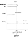
ここで、ポート噴射用インジェクタ10pと筒内噴射用インジェクタ10cとの燃料噴射比率は、基本的に、吸入空気量に応じて定まる内燃機関1の負荷率に基づいて設定される。この場合、加速時や減速時といった内燃機関1の過渡状態において負荷率が急変すると、それに応じて、ポート噴射用インジェクタ10pと筒内噴射用インジェクタ10cとの切り換えや、燃料噴射比率の大幅な変更が実行されることになる。しかしながら、何ら対策を施さない場合、図2に示されるように、車両の運転者によるアクセルペダルAPの操作時と、ポート噴射用インジェクタ10pと筒内噴射用インジェクタ10cとの燃料噴射比率の設定時との間のタイムラグが比較的大きくなってしまうことがあり、それにより、内燃機関1のトルク変動や空燃比の目標値からのズレが発生してドライバビリティやエミッションを悪化させてしまうおそれがある。
Here, the fuel injection ratio between the
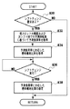
このような点を考慮して、本実施形態の内燃機関1では、ポート噴射用インジェクタ10pと筒内噴射用インジェクタ10cとの燃料噴射比率の変更に伴うトルク変動や空燃比のズレを抑制してドライバビリティの向上やエミッションの低減化を図るべく、ECU20によって、図3に示されるルーチンが所定時間おきに繰り返し実行される。この場合、ECU20は、内燃機関1の作動中、スロットル開度センサ14cからの信号に基づいてスロットルバルブ14の開度(スロットル開度)TAの単位時間あたりの変化量ΔTAを求めると共に、求めた変化量ΔTAに基づいて内燃機関1の運転状態が過渡状態にあるか否か判定する(S10)。S10において、ECU20は、スロットル開度TAの変化量ΔTAの絶対値が所定値を上回っている場合、内燃機関1の運転状態が過渡状態にあると判断する。
Considering these points, the internal combustion engine 1 of the present embodiment suppresses torque fluctuations and air-fuel ratio deviations associated with changes in the fuel injection ratio between the
S10にて、車両の運転者によるアクセル操作量が大きく変化して内燃機関1の運転状態が過渡状態に入ったと判断した場合、ECU20は、S12にて、クランク角センサ22からの信号に基づいてその時点の機関回転数Neを取得すると共に、スロットル開度センサ14cからの信号に基づいてその時点のスロットル開度TAを取得し、更に、取得した機関回転数Neとスロットル開度TAとに基づいて、運転者によるアクセル操作直後の負荷率(予測負荷率、図2における破線参照)を予測(取得)する。本実施形態では、各種実験結果等を踏まえて、機関回転数Neおよびスロットル開度TAと内燃機関1の負荷率(予測負荷率)との相関を規定する負荷率予測マップが予め作成されており、ECU20の記憶装置に格納されている。そして、S12において、ECU20は、負荷率予測マップからS12にて取得した機関回転数Neおよびスロットル開度TAに対応した予測負荷率を読み出す。
If it is determined in S10 that the accelerator operation amount by the driver of the vehicle has greatly changed and the operating state of the internal combustion engine 1 has entered a transient state, the
S12にて予測負荷率を取得すると、ECU20は、予測負荷率に対応したポート噴射用インジェクタ10pと筒内噴射用インジェクタ10cとの燃料噴射比率を取得する(S14)。本実施形態では、内燃機関1の負荷率と、ポート噴射用インジェクタ10pと筒内噴射用インジェクタ10cとの燃料噴射比率との関係を規定する噴射比率設定マップが予め作成されており、ECU20の記憶装置に格納されている。そして、S14において、ECU20は、噴射比率設定マップからS12にて取得した予測負荷率に対応した燃料噴射比率を読み出す。
When the predicted load factor is acquired in S12, the
その後、ECU20は、所定の記憶領域から燃料噴射比率の前回値を読み出すと共に、S14にて取得した燃料噴射比率と前回値との差分をとることにより、燃料噴射比率の変動量(絶対値)を算出する(S16)。例えば、燃料噴射比率の前回値が、ポート噴射用インジェクタ10pからの噴射量:筒内噴射用インジェクタ10cからの噴射量=100%:0%であり、S14にて取得された燃料噴射比率が、ポート噴射用インジェクタ10pからの噴射量:筒内噴射用インジェクタ10cからの噴射量=0%:100%である場合、S16にて算出される燃料噴射比率の変動量は、「100」となる。なお、基本的には、負荷率の変化度合いが大きいほど、S14にて取得した燃料噴射比率と前回値との差分である燃料噴射比率の変動量が大きくなる。
Thereafter, the
そして、ECU20は、燃料噴射比率の変動量が予め定められた閾値(例えば燃料噴射比率の変更によりトルクが変化してショックが体感される値である「30」)を上回っているか否か判定する(S18)。S18にて燃料噴射比率の変動量が上記閾値を上回っていると判断した場合、ECU20は、ポート噴射用インジェクタ10pと筒内噴射用インジェクタ10cとの燃料噴射比率が、S14にて取得した値(予測負荷率に対応した燃料噴射比率)となるように、ポート噴射用インジェクタ10pおよび筒内噴射用インジェクタ10cに所定の制御信号を与える。
Then, the
これにより、過渡状態のもとでポート噴射用インジェクタ10pと筒内噴射用インジェクタ10cとの燃料噴射比率の変更(図2の例では、ポート噴射用インジェクタと筒内噴射用インジェクタとの切り換え)が実行された場合、図2において破線で示されるように、ポート噴射用インジェクタ10pおよび筒内噴射用インジェクタ10cの何れか一方または双方から(図2の例では、筒内噴射用インジェクタ10cから)、予測負荷率に応じて算出された燃料噴射率に従って適切な量の燃料が速やかに噴射されることになる。
Thereby, the change of the fuel injection ratio between the
すなわち、S18にて燃料噴射率の変更処理(S20)が許容されるのは、内燃機関1の運転状態が過渡状態にあり、燃料噴射比率の変動量すなわち負荷率の変化度合いが相対的に大きい場合である。そして、このような場合、ECU20によって求められる予測負荷率は、基本的に、内燃機関1の負荷率に応じて燃料噴射率の変更処理が実行される場合の噴射比率変更負荷率を上回る。従って、内燃機関1では、図2において破線で示されるように、車両の運転者によるアクセルペダルAPの操作時と、ポート噴射用インジェクタ10pと筒内噴射用インジェクタ10cとの燃料噴射比率の変更時との間のタイムラグを従来に比して小さくすることが可能となる。この結果、内燃機関1では、過渡状態のもとで燃料噴射比率の変更(インジェクタの切り換え)を実行する際に、内燃機関1のトルク変動や空燃比の目標値からのズレを良好に抑制して、ドライバビリティを良好に保つと共にエミッションの低減化を図ることが可能となる。
That is, the fuel injection rate changing process (S20) is permitted in S18 because the operating state of the internal combustion engine 1 is in a transient state, and the amount of change in the fuel injection ratio, that is, the degree of change in the load factor is relatively large. Is the case. In such a case, the predicted load factor obtained by the
一方、S18にて燃料噴射比率の変動量が上記閾値を上回っていないと判断される場合、S20の処理はスキップされ、ポート噴射用インジェクタ10pと筒内噴射用インジェクタ10cとの燃料噴射比率の変更処理(インジェクタの切り換え処理)は実行されない。これにより、内燃機関1では、燃料噴射比率の変更回数(インジェクタの切り換え回数)を必要以上に増加させることが抑制されるので、内燃機関1のトルク変動や空燃比の目標値からのズレが発生する確率を低下させることが可能となる。
On the other hand, if it is determined in S18 that the fluctuation amount of the fuel injection ratio does not exceed the threshold value, the process of S20 is skipped and the fuel injection ratio between the
ところで、本実施形態の内燃機関1のECU20は、車速センサ21等と共に、いわゆるクルーズコントロールシステムをも構成することから、車両の運転者によって所定のスイッチがONされている場合には、ECU20によって運転者の意図にかかわらず車両の速度が概ね一定に制御され、車両の走行条件に応じて加減速が実行される。そして、このようにECU20による定速制御が実行されている際(クルーズコントロールシステムがONされている際)に、ポート噴射用インジェクタ10pと筒内噴射用インジェクタ10cとの燃料噴射比率の変更(インジェクタの切り換え)が必要となることもあり得る。しかしながら、ECU20によって車速が概ね一定に保たれている状態では、燃料噴射比率の変更に伴う内燃機関1のトルク変動や空燃比のズレに起因したショックが体感されやすい。
By the way, the
このような点に鑑みて、S10にて内燃機関の運転状態が過渡状態にはないと判断した場合、ECU20は、ECU20による定速制御が実行されているか否か(クルーズコントロールシステムがONされている否か)判定する(S22)。更に、S22にてECU20による定速制御が実行されていると判断した場合、ECU20は、車速センサ21からの信号(車速)およびスロットル開度センサ14cからの信号等に基づいて、車両の走行状態が標準走行状態にあるか否か(登降坂制御時等ではないかどうか)判定する(S24)。
In view of these points, if it is determined in S10 that the operating state of the internal combustion engine is not in a transient state, the
そして、ECU20による定速制御が実行されており、かつ、車両の走行状態が標準走行状態にあると判断した場合(S24)、ECU20は、ポート噴射用インジェクタ10pと筒内噴射用インジェクタ10cとの燃料噴射比率の変更を禁止する(S26)。これにより、内燃機関1では、ECU20による定速制御が実行されている間(クルーズコントロールシステムがONされている間)、基本的に燃料噴射比率の変更(インジェクタの切り換え)が禁止されることになり、燃料噴射比率の変更に伴うトルク変動や空燃比のズレに起因したショックが体感されてしまう頻度を低減することができる。なお、S22およびS24の何れかにおいて否定判断がなされた場合、S26の処理は実行されず、再度S10以降の処理が繰り返される。
When it is determined that the constant speed control by the
図4は、上述の内燃機関1においてポート噴射用インジェクタ10pと筒内噴射用インジェクタ10cとの燃料噴射比率を変更するために実行される他のルーチンを説明するフローチャートである。図4のルーチンは、ECU20によって図2のルーチンに並行して所定時間おきに繰り返し実行されるものである。図4のルーチンを実行する場合、ECU20は、まず、車速センサ21からの信号(車速)およびスロットル開度センサ14cからの信号等に基づいて、自動変速機100に対するシフトチェンジ要求があるか否か判定する(S30)。
FIG. 4 is a flowchart illustrating another routine that is executed in the internal combustion engine 1 to change the fuel injection ratio between the
S30にて自動変速機100に対するシフトチェンジ要求があると判断した場合、ECU20は、スロットル開度センサ14cからの信号に基づいてその時点のスロットル開度TAを取得すると共に、予め定められた関数式等を用いてその時点の運転状態に対応した自動変速機100の次のシフト段における予測回転数Ne´を取得し、取得したスロットル開度TAと予測回転数Ne´とに基づいてシフトチェンジ後の負荷率(予測負荷率)を予測(取得)する(S32)。本実施形態では、各種実験結果等を踏まえて、スロットル開度TAおよび予測回転数Ne´と、内燃機関1の負荷率との相関を規定するマップが予め作成されており、ECU20の記憶装置に格納されている。そして、S32において、ECU20は、当該マップからS32にて取得したスロットル開度TAと予測回転数Ne´とに対応した予測負荷率を読み出す。
If it is determined in S30 that there is a shift change request for the
S32にて予測負荷率を取得すると、ECU20は、予測負荷率に対応したポート噴射用インジェクタ10pと筒内噴射用インジェクタ10cとの燃料噴射比率を取得する(S34)。S34において、ECU20は、上述の噴射比率設定マップからS32にて取得した予測負荷率に対応した燃料噴射比率を読み出す。その後、ECU20は、自動変速機100のシフトチェンジが開始されているか否か判定する(S36)。ECU20は、自動変速機100のシフトチェンジが開始された段階で、ポート噴射用インジェクタ10pと筒内噴射用インジェクタ10cとの燃料噴射比率が、S34にて取得した値(予測負荷率に対応した燃料噴射比率)となるように、ポート噴射用インジェクタ10pおよび筒内噴射用インジェクタ10cに所定の制御信号を与える(S38)。
When the predicted load factor is acquired in S32, the
このように、内燃機関1では、自動変速機100のシフトチェンジのタイミングになると、シフトチェンジ後の負荷率が予測され(S32)、負荷率の予測値(予測負荷率)に基づいてポート噴射用インジェクタ10pと筒内噴射用インジェクタ10cとの燃料噴射比率が算出される(S34)。そして、燃料噴射比率の変更(インジェクタの切り換え)は、シフトチェンジと概ね同時に実行される(S38)。
Thus, in the internal combustion engine 1, when the timing of the shift change of the
この場合も、ポート噴射用インジェクタ10pおよび筒内噴射用インジェクタ10cの何れか一方または双方から、予測負荷率に応じて算出された燃料噴射比率に従って適切な量の燃料が速やかに噴射され、それにより、燃料噴射比率の変更(インジェクタの切り換え)を実行する際に、内燃機関1のトルク変動や空燃比の目標値からのズレを良好に抑制することが可能となる。また、燃料噴射比率の変更により多少のトルク変動等が発生したとしても、体感上許容され得るシフトチェンジ時のショックにより、それらは打ち消されることになる。なお、S30にて自動変速機100に対するシフトチェンジ要求がないと判断された場合、S32からS38までの処理はスキップされ、ECU20は、次の実行タイミングになった段階で図4のルーチンを再度実行する。
Also in this case, an appropriate amount of fuel is promptly injected from one or both of the
1 内燃機関
2 燃焼室
10c 筒内噴射用インジェクタ
10p ポート噴射用インジェクタ
14 スロットルバルブ
14c スロットル開度センサ
20 ECU
21 車速センサ
100 自動変速機
DESCRIPTION OF SYMBOLS 1 Internal combustion engine 2
21
Claims (6)
前記内燃機関の運転状態が過渡状態にあるか否か判定する判定手段と、
前記判定手段によって前記内燃機関の運転状態が過渡状態にあると判定されたとき、前記内燃機関の運転状態と前記内燃機関の負荷率との予め求められた関係を用いて、前記内燃機関の運転状態に基づいて、前記内燃機関の運転状態が変化した後の前記内燃機関の負荷率を予測する負荷予測手段と、
前記判定手段によって前記内燃機関の運転状態が過渡状態にあると判定されたとき、前記負荷予測手段によって予測される前記負荷率に基づいて、前記ポート噴射用インジェクタと前記筒内噴射用インジェクタとの燃料噴射比率を算出する噴射比率算出手段とを備えることを特徴とする内燃機関の制御装置。 A port injection injector that injects fuel into the intake port and an in-cylinder injector that directly injects fuel into the combustion chamber, and generates power by burning a mixture of fuel and air in the combustion chamber In a control device for an internal combustion engine,
Determining means for determining whether the operating state of the internal combustion engine is in a transient state;
When the operating state of the internal combustion engine is determined to be in the transient state by said determining means, using the previously obtained relationship between the load factor of the internal combustion engine and the operating state of the internal combustion engine, operation of the internal combustion engine Load predicting means for predicting the load factor of the internal combustion engine after the operating state of the internal combustion engine has changed based on the state ;
When the determination means determines that the operating state of the internal combustion engine is in a transient state , based on the load factor predicted by the load prediction means, the port injection injector and the in-cylinder injection injector An internal combustion engine control apparatus comprising: an injection ratio calculation means for calculating a fuel injection ratio.
前記噴射比率設定手段は、前記判定手段によって前記内燃機関の運転状態が過渡状態にはないと判断され、かつ、前記定速制御システムが作動されている際に、前記ポート噴射用インジェクタと前記筒内噴射用インジェクタとの燃料噴射比率の変更を禁止することを特徴とする請求項2に記載の内燃機関の制御装置。 The internal combustion engine is applied to a vehicle equipped with a constant speed control system that enables automatic constant speed running,
The injection ratio setting means is configured to determine whether the operation state of the internal combustion engine is not in a transient state by the determination means, and the port injection injector and the cylinder when the constant speed control system is operating. 3. The control device for an internal combustion engine according to claim 2 , wherein the change of the fuel injection ratio with the internal injection injector is prohibited.
前記変速機に対するシフトチェンジ要求の有無を判定する判定手段と、
前記判定手段によってシフトチェンジ要求があると判定されたとき、シフトチェンジ後の前記内燃機関の運転状態を予測し、前記内燃機関の運転状態と前記内燃機関の負荷率との予め求められた関係を用いて、シフトチェンジ後の予測された前記運転状態に基づいて、シフトチェンジ後の前記内燃機関の負荷率を予測する負荷予測手段と、
前記判定手段によってシフトチェンジ要求があると判定されたとき、前記負荷予測手段によって予測される前記負荷率に基づいて、前記ポート噴射用インジェクタと前記筒内噴射用インジェクタとの燃料噴射比率を算出する噴射比率算出手段と、
前記変速機のシフトチェンジ時に、前記ポート噴射用インジェクタと前記筒内噴射用インジェクタとの燃料噴射比率を前記噴射比率算出手段により算出された燃料噴射比率に設定する手段とを備えることを特徴とする内燃機関の制御装置。 It has a port injection injector that injects fuel into the intake port and an in-cylinder injector that directly injects fuel into the combustion chamber, and is combined with a transmission, and a mixture of fuel and air in the combustion chamber In a control device for an internal combustion engine that generates power by burning
Determining means for determining the presence or absence of a shift change request for the transmission;
When it is determined that there is a shift change request by the determining means predicts the operating state of the internal combustion engine after the shift change, the previously obtained relationship between the load factor of the internal combustion engine and the operating state of the internal combustion engine Using a load predicting means for predicting a load factor of the internal combustion engine after the shift change based on the predicted operating state after the shift change ;
When it is determined by the determination means that there is a shift change request , a fuel injection ratio between the port injection injector and the in-cylinder injector is calculated based on the load factor predicted by the load prediction means. Injection ratio calculating means;
And a means for setting a fuel injection ratio between the port injector and the in-cylinder injector to the fuel injection ratio calculated by the injection ratio calculating means at the time of a shift change of the transmission. Control device for internal combustion engine.
(a)前記内燃機関の運転状態が過渡状態にあるか否か判定するステップと、
(b)ステップ(a)にて前記内燃機関の運転状態が過渡状態にあると判定されたとき、前記内燃機関の運転状態と前記内燃機関の負荷率との予め求められた関係を用いて、前記内燃機関の運転状態に基づいて、前記内燃機関の運転状態が変化した後の前記内燃機関の負荷率を予測するステップと、
(c)ステップ(a)にて前記内燃機関の運転状態が過渡状態にあると判定されたとき、ステップ(b)にて予測される前記負荷率に基づいて、前記ポート噴射用インジェクタと前記筒内噴射用インジェクタとの燃料噴射比率を算出するステップとを備える内燃機関の制御方法。 A port injection injector that injects fuel into the intake port and an in-cylinder injector that directly injects fuel into the combustion chamber, and generates power by burning a mixture of fuel and air in the combustion chamber In a control method for an internal combustion engine,
(A) determining whether the operating state of the internal combustion engine is in a transient state;
When the operating state of the internal combustion engine at the step (b) (a) is determined to be in a transient state, using a previously obtained relationship between the load factor of the internal combustion engine and the operating state of the internal combustion engine, Predicting a load factor of the internal combustion engine after the operating state of the internal combustion engine has changed based on the operating state of the internal combustion engine;
(C) When it is determined in step (a) that the operating state of the internal combustion engine is in a transient state, the port injection injector and the cylinder are based on the load factor predicted in step (b). A method for controlling an internal combustion engine comprising: calculating a fuel injection ratio with an internal injection injector.
(a)前記変速機に対するシフトチェンジ要求の有無を判定するステップと、
(b)ステップ(a)にてシフトチェンジ要求があると判定されたとき、シフトチェンジ後の前記内燃機関の運転状態を予測し、前記内燃機関の運転状態と前記内燃機関の負荷率との予め求められた関係を用いて、シフトチェンジ後の予測された前記運転状態に基づいて、シフトチェンジ後の前記内燃機関の負荷率を予測するステップと、
(c)ステップ(a)にてシフトチェンジ要求があると判定されたとき、ステップ(b)にて予測される前記負荷率に基づいて、前記ポート噴射用インジェクタと前記筒内噴射用インジェクタとの燃料噴射比率を算出するステップと、
(d)前記変速機のシフトチェンジ時に、前記ポート噴射用インジェクタと前記筒内噴射用インジェクタとの燃料噴射比率を、前記ステップ(c)にて算出された燃料噴射比率に設定するステップとを備える内燃機関の制御方法。 It has a port injection injector that injects fuel into the intake port and an in-cylinder injector that directly injects fuel into the combustion chamber, and is combined with a transmission, and a mixture of fuel and air in the combustion chamber In a control method of an internal combustion engine for generating power by burning
(A) determining whether or not there is a shift change request for the transmission;
(B) When it is determined in step (a) that there is a shift change request , the operation state of the internal combustion engine after the shift change is predicted, and the operation state of the internal combustion engine and the load factor of the internal combustion engine are preliminarily determined. Predicting a load factor of the internal combustion engine after the shift change based on the predicted operating state after the shift change using the obtained relationship ;
(C) When it is determined in step (a) that there is a shift change request , based on the load factor predicted in step (b), the port injector and the in-cylinder injector Calculating a fuel injection ratio;
(D) setting a fuel injection ratio between the port injector and the in-cylinder injector to the fuel injection ratio calculated in the step (c) at the time of a shift change of the transmission. A method for controlling an internal combustion engine.
Priority Applications (7)
| Application Number | Priority Date | Filing Date | Title |
|---|---|---|---|
| JP2004226035A JP4379251B2 (en) | 2004-08-02 | 2004-08-02 | Control device and control method for internal combustion engine |
| CNB2005800262446A CN100507247C (en) | 2004-08-02 | 2005-06-27 | Device and method for controlling internal combustion engine |
| US11/166,269 US7207315B2 (en) | 2004-08-02 | 2005-06-27 | Device and method for controlling internal combustion engine |
| EP08150788.1A EP1914413B1 (en) | 2004-08-02 | 2005-06-27 | Device and method for controlling an internal combustion engine |
| EP05755750A EP1774159B1 (en) | 2004-08-02 | 2005-06-27 | Device and method for controlling an internal combustion engine |
| DE602005010587T DE602005010587D1 (en) | 2004-08-02 | 2005-06-27 | DEVICE AND METHOD FOR CONTROLLING AN INTERNAL COMBUSTION ENGINE |
| PCT/JP2005/012271 WO2006013688A1 (en) | 2004-08-02 | 2005-06-27 | Device and method for controlling internal combustion engine |
Applications Claiming Priority (1)
| Application Number | Priority Date | Filing Date | Title |
|---|---|---|---|
| JP2004226035A JP4379251B2 (en) | 2004-08-02 | 2004-08-02 | Control device and control method for internal combustion engine |
Publications (2)
| Publication Number | Publication Date |
|---|---|
| JP2006046119A JP2006046119A (en) | 2006-02-16 |
| JP4379251B2 true JP4379251B2 (en) | 2009-12-09 |
Family
ID=34979295
Family Applications (1)
| Application Number | Title | Priority Date | Filing Date |
|---|---|---|---|
| JP2004226035A Expired - Fee Related JP4379251B2 (en) | 2004-08-02 | 2004-08-02 | Control device and control method for internal combustion engine |
Country Status (6)
| Country | Link |
|---|---|
| US (1) | US7207315B2 (en) |
| EP (2) | EP1774159B1 (en) |
| JP (1) | JP4379251B2 (en) |
| CN (1) | CN100507247C (en) |
| DE (1) | DE602005010587D1 (en) |
| WO (1) | WO2006013688A1 (en) |
Families Citing this family (16)
| Publication number | Priority date | Publication date | Assignee | Title |
|---|---|---|---|---|
| US20050262830A1 (en) * | 2002-07-15 | 2005-12-01 | Volkswagen Aktiengesellschaft | Internal combustion engine installation comprising a direct-injection otto engine and a catalyst system |
| US7314033B2 (en) | 2004-11-18 | 2008-01-01 | Massachusetts Institute Of Technology | Fuel management system for variable ethanol octane enhancement of gasoline engines |
| US20080060627A1 (en) | 2004-11-18 | 2008-03-13 | Massachusetts Institute Of Technology | Optimized fuel management system for direct injection ethanol enhancement of gasoline engines |
| US7406947B2 (en) * | 2005-11-30 | 2008-08-05 | Ford Global Technologies, Llc | System and method for tip-in knock compensation |
| US7594493B2 (en) * | 2006-04-24 | 2009-09-29 | Gm Global Technology Operations, Inc. | Method for controlling fuel injection in a compression ignition engine |
| EP2051387A1 (en) | 2007-10-15 | 2009-04-22 | CoreOptics, Inc., c/o The Corporation Trust Center | Receiver, interleaving and deinterleaving circuit and method |
| AT505593B1 (en) | 2008-10-02 | 2010-02-15 | Avl List Gmbh | METHOD FOR OPERATING A FOREIGN IGNITION COMBUSTION ENGINE |
| WO2012131943A1 (en) * | 2011-03-30 | 2012-10-04 | トヨタ自動車株式会社 | Fuel injection control device for internal combustion engine |
| JP6079116B2 (en) * | 2012-10-09 | 2017-02-15 | 三菱自動車工業株式会社 | engine |
| JP6405846B2 (en) * | 2014-09-30 | 2018-10-17 | 三菱自動車工業株式会社 | Engine control device |
| EP3303822B1 (en) | 2015-05-29 | 2021-05-19 | Bombardier Recreational Products Inc. | Internal combustion engine having two fuel injectors per cylinder and control method therefor |
| JP6625889B2 (en) * | 2016-02-01 | 2019-12-25 | 株式会社ケーヒン | Internal combustion engine control device |
| DE102016001399B4 (en) * | 2016-02-06 | 2020-09-17 | Audi Ag | Method and device for operating a drive device, drive device |
| US9885309B1 (en) * | 2016-07-19 | 2018-02-06 | Ford Global Technologies, Llc | Methods and systems for dual fuel injection |
| JP6536613B2 (en) * | 2017-03-30 | 2019-07-03 | トヨタ自動車株式会社 | Control device for internal combustion engine |
| JP2019157652A (en) * | 2018-03-07 | 2019-09-19 | トヨタ自動車株式会社 | Control device of internal combustion engine |
Family Cites Families (11)
| Publication number | Priority date | Publication date | Assignee | Title |
|---|---|---|---|---|
| JP2557640B2 (en) | 1987-04-10 | 1996-11-27 | マツダ株式会社 | Engine fuel injection device |
| JPH01318725A (en) | 1988-06-21 | 1989-12-25 | Mazda Motor Corp | Control device for engine |
| JP2531322B2 (en) | 1991-09-13 | 1996-09-04 | トヨタ自動車株式会社 | Internal combustion engine |
| JP3087538B2 (en) * | 1993-10-12 | 2000-09-11 | トヨタ自動車株式会社 | Internal combustion engine |
| JPH08193535A (en) * | 1995-01-13 | 1996-07-30 | Toyota Motor Corp | Fuel injection controller of internal combustion engine |
| DE19853799A1 (en) | 1998-11-21 | 2000-05-25 | Bayerische Motoren Werke Ag | Mixture formation process for fuel injection engine, producing load-dependent fuel-air mixture by combination if induction pipe injection and direct injection |
| JP2001020837A (en) | 1999-07-07 | 2001-01-23 | Nissan Motor Co Ltd | Fuel injection control device for engine |
| DE10043384A1 (en) | 2000-09-02 | 2002-03-14 | Daimler Chrysler Ag | Fuel metering device for internal combustion engine has controller that regulates amount of fuel injected by injectors in combustion chamber, based on data stored in storage identification field |
| JP2005220887A (en) * | 2004-02-09 | 2005-08-18 | Toyota Motor Corp | Control device for internal combustion engine |
| JP2005248803A (en) * | 2004-03-03 | 2005-09-15 | Toyota Motor Corp | Fuel injection device for internal combustion engine |
| JP4487735B2 (en) * | 2004-11-11 | 2010-06-23 | トヨタ自動車株式会社 | Control device for internal combustion engine |
-
2004
- 2004-08-02 JP JP2004226035A patent/JP4379251B2/en not_active Expired - Fee Related
-
2005
- 2005-06-27 DE DE602005010587T patent/DE602005010587D1/en active Active
- 2005-06-27 US US11/166,269 patent/US7207315B2/en active Active
- 2005-06-27 EP EP05755750A patent/EP1774159B1/en not_active Expired - Fee Related
- 2005-06-27 CN CNB2005800262446A patent/CN100507247C/en not_active Expired - Fee Related
- 2005-06-27 EP EP08150788.1A patent/EP1914413B1/en not_active Expired - Fee Related
- 2005-06-27 WO PCT/JP2005/012271 patent/WO2006013688A1/en active Application Filing
Also Published As
| Publication number | Publication date |
|---|---|
| CN1993543A (en) | 2007-07-04 |
| DE602005010587D1 (en) | 2008-12-04 |
| EP1914413A1 (en) | 2008-04-23 |
| EP1774159B1 (en) | 2008-10-22 |
| EP1914413B1 (en) | 2019-06-19 |
| US7207315B2 (en) | 2007-04-24 |
| WO2006013688A1 (en) | 2006-02-09 |
| CN100507247C (en) | 2009-07-01 |
| US20060021594A1 (en) | 2006-02-02 |
| JP2006046119A (en) | 2006-02-16 |
| EP1774159A1 (en) | 2007-04-18 |
Similar Documents
| Publication | Publication Date | Title |
|---|---|---|
| EP1914413B1 (en) | Device and method for controlling an internal combustion engine | |
| US8005608B2 (en) | Fuel injection control apparatus and fuel injection control method for internal combustion engine | |
| US20100037859A1 (en) | Control device for internal combustion engine, control method, program for performing control method | |
| US7121233B2 (en) | Control apparatus for an internal combustion engine | |
| JP3570875B2 (en) | Fuel injection control device for in-cylinder direct injection engine | |
| JP4477249B2 (en) | In-cylinder injection internal combustion engine control device | |
| JP2008144594A (en) | Vehicle speed limiting device | |
| JP4701683B2 (en) | Vehicle torque control device | |
| JP5018311B2 (en) | Control device for internal combustion engine for vehicle | |
| JP4173059B2 (en) | Cylinder deactivation control device | |
| JP4492811B2 (en) | In-cylinder injection internal combustion engine control device | |
| JP5747832B2 (en) | Control device and control method for internal combustion engine | |
| JPH1136920A (en) | Fuel supply control device for internal combustion engine | |
| JP3865132B2 (en) | Control device for internal combustion engine | |
| JP4024666B2 (en) | Control device for internal combustion engine | |
| JP3908657B2 (en) | Control device for internal combustion engine | |
| JP4497318B2 (en) | Combustion mode switching control device for internal combustion engine | |
| JP3908659B2 (en) | Control device for internal combustion engine | |
| JP3936090B2 (en) | Throttle control device for vehicle engine | |
| JP2004218632A (en) | Fuel injection control device of internal- combustion engine | |
| JP3908658B2 (en) | Control device for internal combustion engine | |
| JP4466540B2 (en) | Fuel injection control device for in-cylinder injection type internal combustion engine | |
| JP4024667B2 (en) | Control device for internal combustion engine | |
| JP4631645B2 (en) | Fuel injection control device for in-cylinder injection type internal combustion engine | |
| JP4497319B2 (en) | Combustion mode switching control device for internal combustion engine |
Legal Events
| Date | Code | Title | Description |
|---|---|---|---|
| RD04 | Notification of resignation of power of attorney |
Free format text: JAPANESE INTERMEDIATE CODE: A7424 Effective date: 20061003 |
|
| RD03 | Notification of appointment of power of attorney |
Free format text: JAPANESE INTERMEDIATE CODE: A7423 Effective date: 20061010 |
|
| A621 | Written request for application examination |
Free format text: JAPANESE INTERMEDIATE CODE: A621 Effective date: 20070109 |
|
| A131 | Notification of reasons for refusal |
Free format text: JAPANESE INTERMEDIATE CODE: A131 Effective date: 20090203 |
|
| A521 | Request for written amendment filed |
Free format text: JAPANESE INTERMEDIATE CODE: A523 Effective date: 20090326 |
|
| TRDD | Decision of grant or rejection written | ||
| A01 | Written decision to grant a patent or to grant a registration (utility model) |
Free format text: JAPANESE INTERMEDIATE CODE: A01 Effective date: 20090825 |
|
| A01 | Written decision to grant a patent or to grant a registration (utility model) |
Free format text: JAPANESE INTERMEDIATE CODE: A01 |
|
| A61 | First payment of annual fees (during grant procedure) |
Free format text: JAPANESE INTERMEDIATE CODE: A61 Effective date: 20090907 |
|
| FPAY | Renewal fee payment (event date is renewal date of database) |
Free format text: PAYMENT UNTIL: 20121002 Year of fee payment: 3 |
|
| R151 | Written notification of patent or utility model registration |
Ref document number: 4379251 Country of ref document: JP Free format text: JAPANESE INTERMEDIATE CODE: R151 |
|
| FPAY | Renewal fee payment (event date is renewal date of database) |
Free format text: PAYMENT UNTIL: 20121002 Year of fee payment: 3 |
|
| FPAY | Renewal fee payment (event date is renewal date of database) |
Free format text: PAYMENT UNTIL: 20131002 Year of fee payment: 4 |
|
| LAPS | Cancellation because of no payment of annual fees |