JP4462079B2 - Control device for internal combustion engine - Google Patents
Control device for internal combustion engine Download PDFInfo
- Publication number
- JP4462079B2 JP4462079B2 JP2005078461A JP2005078461A JP4462079B2 JP 4462079 B2 JP4462079 B2 JP 4462079B2 JP 2005078461 A JP2005078461 A JP 2005078461A JP 2005078461 A JP2005078461 A JP 2005078461A JP 4462079 B2 JP4462079 B2 JP 4462079B2
- Authority
- JP
- Japan
- Prior art keywords
- ignition timing
- fuel injection
- fuel
- internal combustion
- combustion engine
- Prior art date
- Legal status (The legal status is an assumption and is not a legal conclusion. Google has not performed a legal analysis and makes no representation as to the accuracy of the status listed.)
- Expired - Fee Related
Links
Images


Classifications
-
- F—MECHANICAL ENGINEERING; LIGHTING; HEATING; WEAPONS; BLASTING
- F02—COMBUSTION ENGINES; HOT-GAS OR COMBUSTION-PRODUCT ENGINE PLANTS
- F02P—IGNITION, OTHER THAN COMPRESSION IGNITION, FOR INTERNAL-COMBUSTION ENGINES; TESTING OF IGNITION TIMING IN COMPRESSION-IGNITION ENGINES
- F02P5/00—Advancing or retarding ignition; Control therefor
- F02P5/04—Advancing or retarding ignition; Control therefor automatically, as a function of the working conditions of the engine or vehicle or of the atmospheric conditions
- F02P5/145—Advancing or retarding ignition; Control therefor automatically, as a function of the working conditions of the engine or vehicle or of the atmospheric conditions using electrical means
- F02P5/15—Digital data processing
- F02P5/1502—Digital data processing using one central computing unit
-
- F—MECHANICAL ENGINEERING; LIGHTING; HEATING; WEAPONS; BLASTING
- F02—COMBUSTION ENGINES; HOT-GAS OR COMBUSTION-PRODUCT ENGINE PLANTS
- F02D—CONTROLLING COMBUSTION ENGINES
- F02D37/00—Non-electrical conjoint control of two or more functions of engines, not otherwise provided for
- F02D37/02—Non-electrical conjoint control of two or more functions of engines, not otherwise provided for one of the functions being ignition
-
- F—MECHANICAL ENGINEERING; LIGHTING; HEATING; WEAPONS; BLASTING
- F02—COMBUSTION ENGINES; HOT-GAS OR COMBUSTION-PRODUCT ENGINE PLANTS
- F02D—CONTROLLING COMBUSTION ENGINES
- F02D41/00—Electrical control of supply of combustible mixture or its constituents
- F02D41/30—Controlling fuel injection
- F02D41/3094—Controlling fuel injection the fuel injection being effected by at least two different injectors, e.g. one in the intake manifold and one in the cylinder
-
- F—MECHANICAL ENGINEERING; LIGHTING; HEATING; WEAPONS; BLASTING
- F02—COMBUSTION ENGINES; HOT-GAS OR COMBUSTION-PRODUCT ENGINE PLANTS
- F02M—SUPPLYING COMBUSTION ENGINES IN GENERAL WITH COMBUSTIBLE MIXTURES OR CONSTITUENTS THEREOF
- F02M63/00—Other fuel-injection apparatus having pertinent characteristics not provided for in groups F02M39/00 - F02M57/00 or F02M67/00; Details, component parts, or accessories of fuel-injection apparatus, not provided for in, or of interest apart from, the apparatus of groups F02M39/00 - F02M61/00 or F02M67/00; Combination of fuel pump with other devices, e.g. lubricating oil pump
- F02M63/02—Fuel-injection apparatus having several injectors fed by a common pumping element, or having several pumping elements feeding a common injector; Fuel-injection apparatus having provisions for cutting-out pumps, pumping elements, or injectors; Fuel-injection apparatus having provisions for variably interconnecting pumping elements and injectors alternatively
- F02M63/0225—Fuel-injection apparatus having a common rail feeding several injectors ; Means for varying pressure in common rails; Pumps feeding common rails
- F02M63/0275—Arrangement of common rails
- F02M63/0285—Arrangement of common rails having more than one common rail
- F02M63/029—Arrangement of common rails having more than one common rail per cylinder bank, e.g. storing different fuels or fuels at different pressure levels per cylinder bank
-
- F—MECHANICAL ENGINEERING; LIGHTING; HEATING; WEAPONS; BLASTING
- F02—COMBUSTION ENGINES; HOT-GAS OR COMBUSTION-PRODUCT ENGINE PLANTS
- F02M—SUPPLYING COMBUSTION ENGINES IN GENERAL WITH COMBUSTIBLE MIXTURES OR CONSTITUENTS THEREOF
- F02M69/00—Low-pressure fuel-injection apparatus ; Apparatus with both continuous and intermittent injection; Apparatus injecting different types of fuel
- F02M69/04—Injectors peculiar thereto
- F02M69/042—Positioning of injectors with respect to engine, e.g. in the air intake conduit
- F02M69/046—Positioning of injectors with respect to engine, e.g. in the air intake conduit for injecting into both the combustion chamber and the intake conduit
-
- F—MECHANICAL ENGINEERING; LIGHTING; HEATING; WEAPONS; BLASTING
- F02—COMBUSTION ENGINES; HOT-GAS OR COMBUSTION-PRODUCT ENGINE PLANTS
- F02P—IGNITION, OTHER THAN COMPRESSION IGNITION, FOR INTERNAL-COMBUSTION ENGINES; TESTING OF IGNITION TIMING IN COMPRESSION-IGNITION ENGINES
- F02P5/00—Advancing or retarding ignition; Control therefor
- F02P5/04—Advancing or retarding ignition; Control therefor automatically, as a function of the working conditions of the engine or vehicle or of the atmospheric conditions
- F02P5/145—Advancing or retarding ignition; Control therefor automatically, as a function of the working conditions of the engine or vehicle or of the atmospheric conditions using electrical means
- F02P5/15—Digital data processing
- F02P5/152—Digital data processing dependent on pinking
-
- F—MECHANICAL ENGINEERING; LIGHTING; HEATING; WEAPONS; BLASTING
- F02—COMBUSTION ENGINES; HOT-GAS OR COMBUSTION-PRODUCT ENGINE PLANTS
- F02D—CONTROLLING COMBUSTION ENGINES
- F02D41/00—Electrical control of supply of combustible mixture or its constituents
- F02D41/24—Electrical control of supply of combustible mixture or its constituents characterised by the use of digital means
- F02D41/2406—Electrical control of supply of combustible mixture or its constituents characterised by the use of digital means using essentially read only memories
- F02D41/2409—Addressing techniques specially adapted therefor
- F02D41/2422—Selective use of one or more tables
-
- Y—GENERAL TAGGING OF NEW TECHNOLOGICAL DEVELOPMENTS; GENERAL TAGGING OF CROSS-SECTIONAL TECHNOLOGIES SPANNING OVER SEVERAL SECTIONS OF THE IPC; TECHNICAL SUBJECTS COVERED BY FORMER USPC CROSS-REFERENCE ART COLLECTIONS [XRACs] AND DIGESTS
- Y02—TECHNOLOGIES OR APPLICATIONS FOR MITIGATION OR ADAPTATION AGAINST CLIMATE CHANGE
- Y02T—CLIMATE CHANGE MITIGATION TECHNOLOGIES RELATED TO TRANSPORTATION
- Y02T10/00—Road transport of goods or passengers
- Y02T10/10—Internal combustion engine [ICE] based vehicles
- Y02T10/40—Engine management systems
Landscapes
- Engineering & Computer Science (AREA)
- Chemical & Material Sciences (AREA)
- Combustion & Propulsion (AREA)
- Mechanical Engineering (AREA)
- General Engineering & Computer Science (AREA)
- Signal Processing (AREA)
- Theoretical Computer Science (AREA)
- Combined Controls Of Internal Combustion Engines (AREA)
- Electrical Control Of Air Or Fuel Supplied To Internal-Combustion Engine (AREA)
- Electrical Control Of Ignition Timing (AREA)
- Combustion Methods Of Internal-Combustion Engines (AREA)
- Fuel-Injection Apparatus (AREA)
Description
本発明は、筒内に向けて燃料を噴射する第1の燃料噴射手段(筒内噴射用インジェクタ)と吸気通路または吸気ポート内に向けて燃料を噴射する第2の燃料噴射手段(吸気通路噴射用インジェクタ)とを備えた内燃機関の制御装置に関し、特に、第1の燃料噴射手段と第2の燃料噴射手段との分担比率を勘案して、点火時期を決定する技術に関する。 The present invention provides first fuel injection means (in-cylinder injector) for injecting fuel into the cylinder and second fuel injection means (intake passage injection) for injecting fuel into the intake passage or intake port. In particular, the present invention relates to a technique for determining an ignition timing in consideration of a sharing ratio between a first fuel injection unit and a second fuel injection unit.
機関吸気通路内に燃料を噴射するための吸気通路噴射用インジェクタと、機関燃焼室内に燃料を噴射するための筒内噴射用インジェクタとを具備し、機関負荷が予め定められた設定負荷よりも低いときには吸気通路噴射用インジェクタからの燃料噴射を停止するとともに機関負荷が設定負荷よりも高いときには吸気通路噴射用インジェクタから燃料を噴射するようにした内燃機関が公知である。 An intake passage injector for injecting fuel into the engine intake passage and an in-cylinder injector for injecting fuel into the engine combustion chamber are provided, and the engine load is lower than a predetermined set load There are known internal combustion engines that sometimes stop fuel injection from the intake passage injector and inject fuel from the intake passage injector when the engine load is higher than the set load.
また、このような内燃機関において、成層燃焼と均質燃焼とを内燃機関の運転状態に応じて切換えるようにした内燃機関が公知である。成層燃焼とは、圧縮行程中に筒内噴射用インジェクタから燃料を噴射して点火プラグ周辺に集中的に層状の混合気を形成して、燃料を希薄燃焼させる。均質燃焼とは、燃焼室内に燃料を拡散させて均質の混合気を形成して、燃料を燃焼させる。 In such an internal combustion engine, an internal combustion engine in which stratified combustion and homogeneous combustion are switched in accordance with the operating state of the internal combustion engine is known. In stratified combustion, fuel is injected from an in-cylinder injector during a compression stroke, and a stratified mixture is intensively formed around the spark plug to cause lean combustion of the fuel. In homogeneous combustion, fuel is diffused in the combustion chamber to form a homogeneous mixture, and the fuel is combusted.
特開2001−20837号公報(特許文献1)は、成層燃焼および均質燃焼を運転状態により切換えるエンジンであって、燃焼室内に直接燃料を噴射する主燃料噴射弁と各気筒の吸気ポートに燃料を噴射する副燃料噴射弁とを有するエンジンの燃料噴射制御装置を開示する。このエンジンの燃料噴射制御装置は、成層燃焼と均質燃焼とを運転状態に応じて切換えるエンジンの制御装置であって、燃焼室内に直接燃料を噴射する主燃料噴射弁を設けると共に、各気筒の吸気ポートに燃料を噴射する副燃料噴射弁を設け、主燃料噴射弁と副燃料噴射弁の燃料噴射量の分担率を、エンジン運転状態に基づいて可変に設定することを特徴とする。 Japanese Patent Laid-Open No. 2001-20837 (Patent Document 1) is an engine that switches between stratified combustion and homogeneous combustion depending on the operating state, and fuel is injected into a main fuel injection valve that directly injects fuel into a combustion chamber and an intake port of each cylinder. Disclosed is an engine fuel injection control device having an auxiliary fuel injection valve for injection. The engine fuel injection control device is an engine control device that switches between stratified combustion and homogeneous combustion in accordance with an operating state, and includes a main fuel injection valve that directly injects fuel into a combustion chamber, and an intake air for each cylinder. An auxiliary fuel injection valve for injecting fuel is provided in the port, and the share ratio of the fuel injection amount between the main fuel injection valve and the auxiliary fuel injection valve is variably set based on the engine operating state.
このエンジンの燃料噴射制御装置によると、成層燃焼は、主燃料噴射弁から燃焼室内に直接噴射する燃料のみで賄い、均質燃焼を主燃料噴射弁と副燃料噴射弁とを併用(場合によっては副燃料噴射弁のみの使用も可能)することで、高出力エンジンであっても主燃料噴射弁の容量を小さく押さえることができ、以って、アイドルなどの低負荷領域での主燃料噴射弁の噴射期間−噴射量特性のリニアリティが高められ、噴射量制御精度の向上により、成層燃焼を良好に維持でき、アイドルなど低負荷運転の安定性が向上する。均質燃焼時に主燃料噴射弁と副燃料噴射弁とを併用して、直接燃料噴射の利点と、吸気ポート噴射の利点とを活かすことにより、均質燃焼も良好に維持できる。
特許文献1に開示されたエンジンの燃料噴射制御装置においては、成層燃焼と均質燃焼とを使い分けているため、点火制御、噴射制御、スロットル制御が複雑になり、それぞれの燃焼形態に応じた制御プログラムが必要になる。特に、この燃焼形態の切換時には、これらの制御を大きく変更する必要があり、過渡時に良好な制御(燃費、排気浄化性能)を実現することが難しい。また、希薄燃焼となる成層燃焼領域においては三元触媒が機能しないのでリーンNOx触媒を用いなければならないが、コストアップとなる。
In the engine fuel injection control device disclosed in
このような観点から、成層燃焼と均質燃焼との切換時の制御が必要でなく、高コストのリーンNOx触媒の必要もない、成層燃焼を行なわないエンジンも開発されている。 From this point of view, an engine that does not require stratified combustion and that does not require control at the time of switching between stratified combustion and homogeneous combustion, and that does not require a high-cost lean NOx catalyst has been developed.
しかしながら、このようなエンジンの点火制御において、エンジンの冷却水の温度が低いほど、点火時期を進角させるように補正されている。これは、水温が低いほど(霧化状態が良好でなく)燃焼速度が遅くなり、ノッキングも発生しにくくなるからである。点火時期を進角させて点火から排気までの時間を延ばすことにより燃焼速度が遅くても十分に混合気を燃焼させることができる。 However, in such engine ignition control, correction is made so that the ignition timing is advanced as the engine coolant temperature decreases. This is because the lower the water temperature (the atomized state is not good), the slower the combustion speed and the less likely knocking occurs. By advancing the ignition timing and extending the time from ignition to exhaust, the air-fuel mixture can be sufficiently combusted even if the combustion speed is slow.
ところが、冷間時においては低温の吸気通路(吸気ポート)内に燃料を噴射する吸気通路噴射用インジェクタと、冷間であっても高温の筒内に燃料を噴射する筒内噴射用インジェクタとで、燃料噴射を分担している領域においては、燃料の霧化状態が異なるので、筒内噴射用インジェクタから噴射された燃料の状態と、吸気通路噴射用インジェクタから噴射された燃料の状態とが異なる。燃料の霧化状態が異なると混合気の状態が異なり、混合気の燃焼形態が異なり、燃焼形態が異なると最適な点火時期が異なる。このため、エンジン冷却水温だけで点火進角量を求めたのでは、的確な点火時期(進角量)を算出することができない。さらに、冷間時のみならず、冷間時から温間時への過渡期において、筒内噴射用インジェクタと吸気通路噴射用インジェクタとで燃料噴射を分担している領域においては、筒内における温度上昇の度合いと、吸気ポートにおける温度上昇の度合いとが異なるので、エンジン冷却水温だけで点火進角量を求めたのでは、的確な点火進角量を算出することができない。なお、上述した特許文献1においては、運転状態に応じた燃料噴射量分担率になるようにそれぞれのインジェクタを駆動して点火時期を設定するという開示しかなく、上述した問題点の解決策にならない。
However, an intake passage injection injector that injects fuel into a low-temperature intake passage (intake port) when cold, and an in-cylinder injector that injects fuel into a high-temperature cylinder even when cold. In the region where fuel injection is shared, since the atomization state of the fuel is different, the state of the fuel injected from the in-cylinder injector is different from the state of the fuel injected from the intake passage injector. . If the atomization state of the fuel is different, the state of the mixture is different, the combustion mode of the mixture is different, and the optimal ignition timing is different if the combustion mode is different. For this reason, if the ignition advance amount is obtained only from the engine coolant temperature, an accurate ignition timing (advance amount) cannot be calculated. Furthermore, in the region where the fuel injection is shared by the in-cylinder injector and the intake manifold injector in the transition period from the cold time to the warm time as well as in the cold time, the temperature in the cylinder Since the degree of increase is different from the degree of temperature increase at the intake port, if the ignition advance amount is obtained only from the engine coolant temperature, an accurate ignition advance amount cannot be calculated. Note that the above-described
本発明は、上述の課題を解決するためになされたものであって、その目的は、筒内に燃料を噴射する第1の燃料噴射手段と吸気通路に燃料を噴射する第2の燃料噴射手段とで噴射燃料を分担する内燃機関において、冷間時および冷間時から温間時への過渡期において、燃料噴射を分担している場合に、的確な点火時期の変動量を算出することができる、内燃機関の制御装置を提供することである。 The present invention has been made to solve the above-described problems, and has as its object the first fuel injection means for injecting fuel into the cylinder and the second fuel injection means for injecting fuel into the intake passage. In the internal combustion engine that shares the injected fuel, and when the fuel injection is shared during the cold period and the transition period from the cold period to the warm period, it is possible to calculate an accurate amount of ignition timing fluctuation. A control device for an internal combustion engine is provided.
第1の発明に係る内燃機関の制御装置は、筒内に燃料を噴射するための第1の燃料噴射手段と吸気通路内に燃料を噴射するための第2の燃料噴射手段とを備えた内燃機関を制御する。この制御装置は、内燃機関に要求される条件に基づいて算出された比率で、第1の燃料噴射手段と第2の燃料噴射手段とで分担して燃料を噴射するように、燃料噴射手段を制御するための制御手段と、内燃機関の温度を検知するための検知手段と、点火時期を変化させるように点火装置を制御するための点火時期制御手段とを含む。この点火時期制御手段は、内燃機関の冷間時における点火時期変動量を、比率および温度に基づいて算出して、算出された点火時期変動量に基づいて点火時期を変化させるように点火装置を制御するための手段を含む。 An internal combustion engine control apparatus according to a first aspect of the present invention includes an internal combustion engine having a first fuel injection means for injecting fuel into a cylinder and a second fuel injection means for injecting fuel into an intake passage. Control the engine. The control device controls the fuel injection means so that the fuel is injected by the first fuel injection means and the second fuel injection means in a ratio calculated based on conditions required for the internal combustion engine. Control means for controlling, detection means for detecting the temperature of the internal combustion engine, and ignition timing control means for controlling the ignition device so as to change the ignition timing. The ignition timing control means calculates the ignition timing fluctuation amount when the internal combustion engine is cold based on the ratio and the temperature, and changes the ignition timing based on the calculated ignition timing fluctuation amount. Means for controlling.
第1の発明によると、第1の燃料噴射手段(たとえば筒内噴射用インジェクタ)と第2の燃料噴射手段(たとえば吸気通路噴射用インジェクタ)とで燃料噴射を分担している領域においては、筒内における温度上昇の度合いと、吸気ポートにおける温度上昇の度合いとが異なる。冷間時および冷間時から温間時への過渡期においては、この温度の差により点火時期を進角または遅角させる度合いが異なる。点火時期制御手段は、筒内に噴射される燃料と吸気ポートに噴射される燃料との比率を考慮して、内燃機関の温度(たとえばエンジン冷却水温)に基づいて冷間時における進角量または遅角量(これらを合わせて点火時期の変動量という)を算出する。このため、噴射部位が異なる2つの燃料噴射手段で燃料を分担している内燃機関において、冷間時の点火時期を的確に進角または遅角させることができる。その結果、冷間時および冷間時から温間時への過渡期において、燃料噴射を分担している場合に、的確な点火時期の変動量を算出することができる、内燃機関の制御装置を提供することができる。 According to the first invention, in the region where fuel injection is shared by the first fuel injection means (for example, the in-cylinder injector) and the second fuel injection means (for example, the intake manifold injector), the cylinder The degree of temperature rise in the interior is different from the degree of temperature rise in the intake port. In the cold period and in the transition period from the cold period to the warm period, the degree to which the ignition timing is advanced or retarded varies depending on the temperature difference. The ignition timing control means takes into account the ratio of the fuel injected into the cylinder and the fuel injected into the intake port, and based on the temperature of the internal combustion engine (for example, the engine coolant temperature) The retard amount (which is referred to as the amount of change in the ignition timing) is calculated. For this reason, in an internal combustion engine in which fuel is shared by two fuel injection means having different injection parts, the ignition timing in the cold state can be advanced or retarded accurately. As a result, a control device for an internal combustion engine that can accurately calculate the amount of fluctuation of the ignition timing when the fuel injection is shared in the cold period and in the transition period from the cold period to the warm period. Can be provided.
第2の発明に係る内燃機関の制御装置は、筒内に燃料を噴射するための第1の燃料噴射手段と吸気通路内に燃料を噴射するための第2の燃料噴射手段とを備えた内燃機関を制御する。この制御装置は、内燃機関に要求される条件に基づいて算出された比率で、第1の燃料噴射手段と第2の燃料噴射手段とで分担して燃料を噴射するように、燃料噴射手段を制御するための制御手段と、内燃機関の温度を検知するための検知手段と、基本点火時期を算出するための算出手段と、点火時期変動量を用いて基本点火時期を変化させるように点火装置を制御するための点火時期制御手段とを含む。点火時期制御手段は、内燃機関の冷間時における点火時期変動量を、比率および温度に基づいて算出して、算出された点火時期変動量を用いて基本点火時期を変化させるように点火装置を制御するための手段を含む。 An internal combustion engine control apparatus according to a second aspect of the invention includes an internal combustion engine having a first fuel injection means for injecting fuel into a cylinder and a second fuel injection means for injecting fuel into an intake passage. Control the engine. The control device controls the fuel injection means so that the fuel is injected by the first fuel injection means and the second fuel injection means in a ratio calculated based on conditions required for the internal combustion engine. Control means for controlling, detection means for detecting the temperature of the internal combustion engine, calculation means for calculating the basic ignition timing, and ignition device so as to change the basic ignition timing using the ignition timing fluctuation amount Ignition timing control means for controlling the engine. The ignition timing control means calculates the ignition timing fluctuation amount when the internal combustion engine is cold based on the ratio and the temperature, and changes the basic ignition timing using the calculated ignition timing fluctuation amount. Means for controlling.
第2の発明によると、第1の燃料噴射手段(たとえば筒内噴射用インジェクタ)と第2の燃料噴射手段(たとえば吸気通路噴射用インジェクタ)とで燃料噴射を分担している領域においては、筒内における温度上昇の度合いと、吸気ポートにおける温度上昇の度合いとが異なる。冷間時および冷間時から温間時への過渡期においては、この温度の差により点火時期を進角または遅角させる度合いが異なる。点火時期制御手段は、筒内に噴射される燃料と吸気ポートに噴射される燃料との比率を考慮して、内燃機関の温度(たとえばエンジン冷却水温)に基づいて冷間時における進角補正量または遅角補正量を算出する。この進角補正量または遅角補正量を用いて、内燃機関の運転状態に基づいて算出された基本点火時期を変化させる。このため、噴射部位が異なる2つの燃料噴射手段で燃料を分担している内燃機関において、冷間時の点火時期を的確に変動させることができる。その結果、冷間時および冷間時から温間時への過渡期において、燃料噴射を分担している場合に、的確な点火時期の変動量を算出することができる、内燃機関の制御装置を提供することができる。 According to the second invention, in the region where fuel injection is shared by the first fuel injection means (for example, in-cylinder injector) and the second fuel injection means (for example, intake manifold injector), the cylinder The degree of temperature rise in the interior is different from the degree of temperature rise in the intake port. In the cold period and in the transition period from the cold period to the warm period, the degree to which the ignition timing is advanced or retarded varies depending on the temperature difference. The ignition timing control means takes into account the ratio between the fuel injected into the cylinder and the fuel injected into the intake port, and based on the temperature of the internal combustion engine (for example, the engine coolant temperature), the advance angle correction amount in the cold state Alternatively, the retardation correction amount is calculated. Using this advance angle correction amount or retard angle correction amount, the basic ignition timing calculated based on the operating state of the internal combustion engine is changed. For this reason, in the internal combustion engine in which the fuel is shared by the two fuel injection means having different injection parts, the ignition timing in the cold state can be accurately changed. As a result, a control device for an internal combustion engine that can accurately calculate the amount of fluctuation of the ignition timing when the fuel injection is shared in the cold period and in the transition period from the cold period to the warm period. Can be provided.
第3の発明に係る内燃機関の制御装置は、筒内に燃料を噴射するための第1の燃料噴射手段と吸気通路内に燃料を噴射するための第2の燃料噴射手段とを備えた内燃機関を制御する。この制御装置は、内燃機関に要求される条件に基づいて算出された比率で、第1の燃料噴射手段と第2の燃料噴射手段とで分担して燃料を噴射するように、燃料噴射手段を制御するための制御手段と、内燃機関の温度を検知するための検知手段と、点火時期を変化させるように点火装置を制御するための点火時期制御手段とを含む。この点火時期制御手段は、内燃機関の冷間時における進角量を、比率および温度に基づいて算出して、算出された進角量に基づいて点火時期を変化させるように点火装置を制御するための手段を含む。 An internal combustion engine control apparatus according to a third aspect of the invention includes an internal combustion engine that includes a first fuel injection means for injecting fuel into a cylinder and a second fuel injection means for injecting fuel into an intake passage. Control the engine. The control device controls the fuel injection means so that the fuel is injected by the first fuel injection means and the second fuel injection means in a ratio calculated based on conditions required for the internal combustion engine. Control means for controlling, detection means for detecting the temperature of the internal combustion engine, and ignition timing control means for controlling the ignition device so as to change the ignition timing. The ignition timing control means calculates the advance amount when the internal combustion engine is cold based on the ratio and the temperature, and controls the ignition device so as to change the ignition timing based on the calculated advance amount. Means for.
第3の発明によると、第1の燃料噴射手段(たとえば筒内噴射用インジェクタ)と第2の燃料噴射手段(たとえば吸気通路噴射用インジェクタ)とで燃料噴射を分担している領域においては、筒内における温度上昇の度合いと、吸気ポートにおける温度上昇の度合いとが異なる。冷間時および冷間時から温間時への過渡期においては、この温度の差により点火時期を進角させる度合いが異なる。点火時期制御手段は、筒内に噴射される燃料と吸気ポートに噴射される燃料との比率を考慮して、内燃機関の温度(たとえばエンジン冷却水温)に基づいて冷間時における進角量を算出する。このため、噴射部位が異なる2つの燃料噴射手段で燃料を分担している内燃機関において、冷間時の点火時期を的確に進角させることができる。その結果、冷間時および冷間時から温間時への過渡期において、燃料噴射を分担している場合に、的確な点火時期の進角量を算出することができる、内燃機関の制御装置を提供することができる。 According to the third aspect of the present invention, in the region where the fuel injection is shared by the first fuel injection means (for example, in-cylinder injector) and the second fuel injection means (for example, intake manifold injector), the cylinder The degree of temperature rise in the interior is different from the degree of temperature rise in the intake port. In the cold period and in the transition period from the cold period to the warm period, the degree to which the ignition timing is advanced differs depending on the temperature difference. The ignition timing control means determines the advance amount in the cold state based on the temperature of the internal combustion engine (for example, the engine coolant temperature) in consideration of the ratio of the fuel injected into the cylinder and the fuel injected into the intake port. calculate. For this reason, in the internal combustion engine in which the fuel is shared by the two fuel injection means having different injection parts, the ignition timing in the cold state can be advanced accurately. As a result, a control device for an internal combustion engine capable of calculating an accurate advance amount of the ignition timing when the fuel injection is shared during the cold period and the transition period from the cold period to the warm period Can be provided.
第4の発明に係る内燃機関の制御装置は、筒内に燃料を噴射するための第1の燃料噴射手段と吸気通路内に燃料を噴射するための第2の燃料噴射手段とを備えた内燃機関を制御する。この制御装置は、内燃機関に要求される条件に基づいて算出された比率で、第1の燃料噴射手段と第2の燃料噴射手段とで分担して燃料を噴射するように、燃料噴射手段を制御するための制御手段と、内燃機関の温度を検知するための検知手段と、基本点火時期を算出するための算出手段と、進角補正量を用いて基本点火時期を変化させるように点火装置を制御するための点火時期制御手段とを含む。点火時期制御手段は、内燃機関の冷間時における進角補正量を、比率および温度に基づいて算出して、算出された進角補正量を用いて基本点火時期を変化させるように点火装置を制御するための手段を含む。 An internal combustion engine control apparatus according to a fourth aspect of the present invention includes an internal combustion engine having a first fuel injection means for injecting fuel into a cylinder and a second fuel injection means for injecting fuel into an intake passage. Control the engine. The control device controls the fuel injection means so that the fuel is injected by the first fuel injection means and the second fuel injection means in a ratio calculated based on conditions required for the internal combustion engine. Control means for controlling, detection means for detecting the temperature of the internal combustion engine, calculation means for calculating the basic ignition timing, and ignition device so as to change the basic ignition timing using the advance correction amount Ignition timing control means for controlling the engine. The ignition timing control means calculates the advance correction amount when the internal combustion engine is cold based on the ratio and temperature, and changes the basic ignition timing using the calculated advance correction amount. Means for controlling.
第4の発明によると、第1の燃料噴射手段(たとえば筒内噴射用インジェクタ)と第2の燃料噴射手段(たとえば吸気通路噴射用インジェクタ)とで燃料噴射を分担している領域においては、筒内における温度上昇の度合いと、吸気ポートにおける温度上昇の度合いとが異なる。冷間時および冷間時から温間時への過渡期においては、この温度の差により点火時期を進角させる度合いが異なる。点火時期制御手段は、筒内に噴射される燃料と吸気ポートに噴射される燃料との比率を考慮して、内燃機関の温度(たとえばエンジン冷却水温)に基づいて冷間時における進角補正量を算出する。この進角補正量を用いて、内燃機関の運転状態に基づいて算出された基本点火時期を変化させる。このため、噴射部位が異なる2つの燃料噴射手段で燃料を分担している内燃機関において、冷間時の点火時期を的確に進角させることができる。その結果、冷間時および冷間時から温間時への過渡期において、燃料噴射を分担している場合に、的確な点火時期の進角量を算出することができる、内燃機関の制御装置を提供することができる。 According to the fourth aspect of the invention, in the region where fuel injection is shared by the first fuel injection means (for example, in-cylinder injector) and the second fuel injection means (for example, intake manifold injector), the cylinder The degree of temperature rise in the interior is different from the degree of temperature rise in the intake port. In the cold period and in the transition period from the cold period to the warm period, the degree to which the ignition timing is advanced differs depending on the temperature difference. The ignition timing control means takes into account the ratio between the fuel injected into the cylinder and the fuel injected into the intake port, and based on the temperature of the internal combustion engine (for example, the engine coolant temperature), the advance angle correction amount in the cold state Is calculated. The basic ignition timing calculated based on the operating state of the internal combustion engine is changed using the advance correction amount. For this reason, in the internal combustion engine in which the fuel is shared by the two fuel injection means having different injection parts, the ignition timing in the cold state can be advanced accurately. As a result, a control device for an internal combustion engine capable of calculating an accurate advance amount of the ignition timing when the fuel injection is shared during the cold period and the transition period from the cold period to the warm period Can be provided.
第5の発明に係る内燃機関の制御装置においては、第3または4の発明の構成に加えて、点火時期制御手段は、第1の燃料噴射手段の比率が高いほど、進角量が小さくなるように算出するための手段を含む。 In the control apparatus for an internal combustion engine according to the fifth invention, in addition to the configuration of the third or fourth invention, the ignition timing control means has a smaller advance amount as the ratio of the first fuel injection means is higher. Means for calculating as follows.
第5の発明によると、第1の燃料噴射手段として筒内に燃料を噴射する筒内噴射用インジェクタがあるが、筒内の温度は吸気ポートの温度よりも高い。このため、筒内噴射用インジェクタから噴射される燃料の比率が高いほど、点火時期を大きく進角させる必要がなく、進角量は小さくても所望の燃焼形態を実現できる。 According to the fifth invention, there is an in-cylinder injector that injects fuel into the cylinder as the first fuel injection means, but the temperature in the cylinder is higher than the temperature of the intake port. For this reason, the higher the ratio of the fuel injected from the in-cylinder injector, the more the ignition timing does not need to be advanced, and the desired combustion mode can be realized even if the amount of advance is small.
第6の発明に係る内燃機関の制御装置においては、第3または4の発明の構成に加えて、点火時期制御手段は、第2の燃料噴射手段の比率が高いほど、進角量が大きくなるように算出するための手段を含む。 In the control apparatus for an internal combustion engine according to the sixth invention, in addition to the configuration of the third or fourth invention, the ignition timing control means has a larger advance amount as the ratio of the second fuel injection means is higher. Means for calculating as follows.
第6の発明によると、第2の燃料噴射手段として吸気ポートに燃料を噴射する吸気通路噴射用インジェクタがあるが、吸気ポートの温度は筒内の温度よりも低い。このため、吸気通路噴射用インジェクタから噴射される燃料の比率が高いほど、点火時期を大きく進角させることにより所望の燃焼形態を実現できる。 According to the sixth invention, there is an intake passage injection injector for injecting fuel into the intake port as the second fuel injection means, but the temperature of the intake port is lower than the temperature in the cylinder. For this reason, as the ratio of the fuel injected from the intake manifold injector is higher, the desired combustion mode can be realized by advancing the ignition timing.
第7の発明に係る内燃機関の制御装置においては、第3〜6のいずれかの発明の構成に加えて、点火時期制御手段は、温度が高いほど、進角量が小さくなるように算出するための手段を含む。 In the control apparatus for an internal combustion engine according to the seventh aspect of the invention, in addition to the configuration of any one of the third to sixth aspects, the ignition timing control means calculates so that the higher the temperature, the smaller the advance amount. Means for.
第7の発明によると、内燃機関の温度が高いほど燃料は霧化しやすいので、点火時期を大きく進角させる必要がなく、進角量は小さくても所望の燃焼形態を実現できる。 According to the seventh invention, the higher the temperature of the internal combustion engine, the more easily the fuel is atomized. Therefore, it is not necessary to greatly advance the ignition timing, and a desired combustion mode can be realized even if the amount of advance is small.
第8の発明に係る内燃機関の制御装置においては、第3〜6のいずれかの発明の構成に加えて、点火時期制御手段は、温度が低いほど、進角量が大きくなるように算出するための手段を含む。 In the control apparatus for an internal combustion engine according to the eighth aspect of the invention, in addition to the configuration of any one of the third to sixth aspects, the ignition timing control means calculates so that the advance amount increases as the temperature decreases. Means for.
第8の発明によると、内燃機関の温度が低いほど燃料は霧化しにくいので、点火時期を大きく進角させることにより所望の燃焼形態を実現できる。 According to the eighth aspect of the invention, the lower the temperature of the internal combustion engine, the more difficult the fuel is atomized. Therefore, the desired combustion mode can be realized by greatly advancing the ignition timing.
第9の発明に係る内燃機関の制御装置は、筒内に燃料を噴射するための第1の燃料噴射手段と吸気通路内に燃料を噴射するための第2の燃料噴射手段とを備えた内燃機関を制御する。この制御装置は、内燃機関に要求される条件に基づいて算出された、一方の燃料噴射手段による燃料噴射が停止する場合を含む比率で、第1の燃料噴射手段と第2の燃料噴射手段とで分担して燃料を噴射するように、燃料噴射手段を制御するための制御手段と、内燃機関の温度を検知するための検知手段と、基本点火時期および冷間時の点火時期変動量を記憶するための記憶手段と、基本点火時期から点火時期変動量の分だけ点火時期を変動させて点火装置を制御するための点火時期制御手段とを含む。記憶手段は、燃料噴射手段から噴射された燃料と空気との混合気の状態に基づいて算出された内燃機関の冷間時における点火時期変動量を記憶するための手段を含む。 An internal combustion engine control apparatus according to a ninth aspect of the invention includes an internal combustion engine that includes a first fuel injection means for injecting fuel into a cylinder and a second fuel injection means for injecting fuel into an intake passage. Control the engine. The control apparatus calculates the first fuel injection means and the second fuel injection means at a ratio calculated based on conditions required for the internal combustion engine, including the case where the fuel injection by one fuel injection means stops. The control means for controlling the fuel injection means, the detection means for detecting the temperature of the internal combustion engine, and the basic ignition timing and the cold ignition timing fluctuation amount are stored so Storage means for controlling the ignition device, and ignition timing control means for controlling the ignition device by changing the ignition timing by an amount corresponding to the ignition timing fluctuation amount from the basic ignition timing. The storage means includes means for storing an ignition timing fluctuation amount when the internal combustion engine is cold, which is calculated based on a state of a mixture of fuel and air injected from the fuel injection means.
第9の発明によると、冷間時において、第1の燃料噴射手段(たとえば筒内噴射用インジェクタ)と第2の燃料噴射手段(たとえば吸気通路噴射用インジェクタ)とで燃料噴射を分担している領域においては、筒内噴射用インジェクタにより燃料が噴射される筒内の温度(高温)に起因する燃料の霧化状態(良好)と、吸気通路噴射用インジェクタにより燃料が噴射される吸気通路の温度(低温)に起因する燃料の霧化状態(不良)との差異により、燃料と空気との混合気の状態とが異なる。すなわち、燃料と空気との混合気の状態が異なるのは、冷間時における燃料の霧化状態の違いがその要因の1つとして挙げられる。冷間時においても、筒内噴射用インジェクタは高温の筒内に燃料を噴射するので、その燃料の霧化状態が良好であって、良好な霧化状態の燃料と空気との混合気の均質性が良好となり、混合気の燃焼速度が速い。一方、吸気通路噴射用インジェクタは低温の吸気管内に燃料を噴射するのでその霧化状態が良好でなく、良好でない霧化状態の燃料と空気との混合気の均質性が良好でなく、混合気の燃焼速度が遅い。そのため、燃料噴射手段の分担比率に加えて内燃機関の温度等を考慮した、混合気の状態(霧化状態、均質状態等)に基づいて算出された点火時期変動量の分だけ基本点火時期から点火時期を変動させて最適な点火時期になるように点火装置が制御される。このため、噴射による混合気の状態が異なる2つの燃料噴射手段で燃料を分担している内燃機関において、点火時期を的確に設定することができる。その結果、筒内に燃料を噴射する第1の燃料噴射手段と吸気通路に燃料を噴射する第2の燃料噴射手段とで噴射燃料を分担する内燃機関において、燃料噴射状態の異なる2種類の燃料噴射手段で燃料噴射を分担している場合に、的確な点火時期を算出することができる、内燃機関の制御装置を提供することができる。 According to the ninth aspect of the invention, fuel injection is shared by the first fuel injection means (for example, the in-cylinder injector) and the second fuel injection means (for example, the intake passage injection injector) when cold. In the region, the fuel atomization state (good) caused by the in-cylinder temperature (high temperature) at which the fuel is injected by the in-cylinder injector, and the temperature of the intake passage through which the fuel is injected by the intake passage injector Due to the difference from the fuel atomization state (defective) caused by (low temperature), the state of the mixture of fuel and air differs. That is, the difference in the state of the mixture of fuel and air can be attributed to the difference in the atomization state of the fuel during cold. Even in cold weather, the in-cylinder injector injects fuel into the high-temperature cylinder, so that the fuel atomization state is good and the mixture of fuel and air in a good atomization state is homogeneous. The air-fuel mixture burns quickly. On the other hand, since the injector for injecting the intake passage injects fuel into the low-temperature intake pipe, the atomization state is not good, and the homogeneity of the mixture of fuel and air in the poor atomization state is not good. The burning speed of is slow. Therefore, from the basic ignition timing, the amount of variation in the ignition timing calculated based on the state of the air-fuel mixture (atomization state, homogeneous state, etc.) considering the temperature of the internal combustion engine in addition to the share ratio of the fuel injection means The ignition device is controlled so that the ignition timing is varied to obtain an optimal ignition timing. For this reason, in the internal combustion engine in which the fuel is shared by the two fuel injection means having different states of the air-fuel mixture by the injection, the ignition timing can be set accurately. As a result, in the internal combustion engine in which the injected fuel is shared by the first fuel injection means for injecting fuel into the cylinder and the second fuel injection means for injecting fuel into the intake passage, two types of fuel having different fuel injection states When the fuel injection is shared by the injection means, it is possible to provide a control device for an internal combustion engine that can calculate an accurate ignition timing.
第10の発明に係る内燃機関の制御装置においては、第9の発明の構成に加えて、記憶手段は、温度および比率に基づいて算出された内燃機関の冷間時における点火時期変動量を記憶するための手段を含む。 In the control apparatus for an internal combustion engine according to the tenth invention, in addition to the configuration of the ninth invention, the storage means stores the ignition timing fluctuation amount during the cold time of the internal combustion engine calculated based on the temperature and the ratio. Means for doing so.
第10の発明によると、温度および比率に起因する燃料の霧化状態に起因して異なる混合気の状態に基づいて点火時期変動量が算出される。算出された点火時期変動量の分だけ基本点火時期から点火時期を変動させて最適な点火時期になるように点火装置が制御される。 According to the tenth aspect of the invention, the ignition timing fluctuation amount is calculated based on the state of the different air-fuel mixture due to the fuel atomization state caused by the temperature and the ratio. The ignition device is controlled so that the ignition timing is changed from the basic ignition timing by an amount corresponding to the calculated ignition timing fluctuation amount so that the optimal ignition timing is obtained.
第11の発明に係る内燃機関の制御装置においては、第10の発明の構成に加えて、記憶手段は、点火時期変動量をマップとして記憶するための手段を含む。 In the control apparatus for an internal combustion engine according to the eleventh invention, in addition to the structure of the tenth invention, the storage means includes means for storing the ignition timing variation as a map.
第11の発明によると、筒内噴射用インジェクタと吸気通路噴射用インジェクタとの分担比率に基づいてマップとして記憶された点火時期変動量を用いて、基本点火時期から点火時期変動分だけ進角または遅角された最適な点火時期を決定することができる。 According to the eleventh invention, the ignition timing fluctuation amount stored as a map based on the sharing ratio between the in-cylinder injector and the intake manifold injector is used to advance the ignition timing fluctuation from the basic ignition timing by the ignition timing fluctuation amount. An optimal retarded ignition timing can be determined.
第12の発明に係る内燃機関の制御装置においては、第11の発明の構成に加えて、記憶手段は、点火時期変動量を、第1の燃料噴射手段のみにより燃料噴射される場合の第1のマップ、第2の燃料噴射手段のみにより燃料噴射される場合の第2のマップ、第1の燃料噴射手段および第2の燃料噴射手段により燃料噴射される場合の第3のマップに分けて、記憶するための手段を含む。 In the control apparatus for an internal combustion engine according to the twelfth aspect of the invention, in addition to the configuration of the eleventh aspect of the invention, the storage means is the first in the case where the ignition timing variation is injected only by the first fuel injection means. The map is divided into a second map when fuel is injected only by the second fuel injection means, and a third map when fuel is injected by the first fuel injection means and the second fuel injection means, Means for storing.
第12の発明によると、燃料の分担率や内燃機関の温度に起因して、燃料と空気との混合気の状態(霧化状態、均質状態等)が異なる。第1の燃料噴射手段の一例である筒内噴射用インジェクタと、第2の燃料噴射手段の一例である吸気通路噴射用インジェクタとで、燃料噴射が分担される場合において、筒内噴射用インジェクタのみにより燃料噴射される場合の第1のマップ、吸気通路噴射用インジェクタのみにより燃料噴射される場合の第2のマップ、筒内噴射用インジェクタおよび吸気通路噴射用インジェクタにより燃料噴射される場合の第3のマップに分けて、基本点火時期からの変動量をマップとして記憶させる。筒内噴射用インジェクタと吸気通路噴射用インジェクタとの燃料噴射の分担比率に基づいて、マップを選択して、基本点火時期からの変動量を決定することができる。このとき、それぞれのマップは、内燃機関の温度をパラメータとして点火時期変動量を記憶するようにすればよい。 According to the twelfth aspect, the state of the air-fuel mixture (atomization state, homogeneous state, etc.) differs between the fuel and air due to the share of fuel and the temperature of the internal combustion engine. When the fuel injection is shared by the in-cylinder injector, which is an example of the first fuel injection means, and the intake passage injector, which is an example of the second fuel injection means, only the in-cylinder injector The first map when fuel is injected by the second, the second map when fuel is injected only by the intake passage injector, the third map when fuel is injected by the in-cylinder injector and the intake passage injector The amount of variation from the basic ignition timing is stored as a map. Based on the share ratio of fuel injection between the in-cylinder injector and the intake manifold injector, a map can be selected to determine the amount of variation from the basic ignition timing. At this time, each map may store the ignition timing fluctuation amount using the temperature of the internal combustion engine as a parameter.
第13の発明に係る内燃機関の制御装置においては、第12の発明の構成に加えて、第1のマップにおける点火時期変動量は、遅角側に設定されるものである。 In the control device for an internal combustion engine according to the thirteenth invention, in addition to the configuration of the twelfth invention, the ignition timing fluctuation amount in the first map is set to the retard side.
第13の発明によると、第1の燃料噴射手段(たとえば筒内噴射用インジェクタ)のみにより燃料噴射される場合の第1のマップにおいては、筒内噴射用インジェクタから噴射された(特に圧縮行程において噴射された)燃料の霧化状態が冷間時であっても良好で、燃料と空気との混合気の均質性が良好であって燃焼速度が速い。そのため、基本的には、点火時期が遅角側に設定されるように点火時期変動量を記憶する。特に、内燃機関の温度が高いほど、このような傾向が大きくなるので、内燃機関の温度をパラメータにすればよい。ただし、筒内噴射用インジェクタから噴射される燃料は、筒内が高温であるので霧化状態が良好であっても、噴射から点火までの混合期間が短く、燃料の霧化状態が良好であっても空気との均質性が良好でないこともあり得る。そのため、筒内噴射用インジェクタによる、混合期間の短さに起因する混合気の均質不良性と、筒内が高温であることに起因する燃料の霧化良好性との関係から、点火時期の変動量が決定される。 According to the thirteenth invention, in the first map when fuel is injected only by the first fuel injection means (for example, in-cylinder injector), the fuel is injected from the in-cylinder injector (particularly in the compression stroke). It is good even when the state of atomization of the injected fuel is cold, the homogeneity of the mixture of fuel and air is good, and the combustion rate is fast. Therefore, basically, the ignition timing fluctuation amount is stored so that the ignition timing is set to the retard side. In particular, the higher the temperature of the internal combustion engine, the greater the tendency, so the temperature of the internal combustion engine may be used as a parameter. However, the fuel injected from the in-cylinder injector is hot in the cylinder, so even if the atomization state is good, the mixing period from injection to ignition is short and the fuel atomization state is good. However, the homogeneity with air may not be good. Therefore, fluctuations in ignition timing are caused by the relationship between the poor homogeneity of the air-fuel mixture due to the short mixing period and the good atomization of fuel due to the high temperature in the cylinder due to the in-cylinder injector. The amount is determined.
第14の発明に係る内燃機関の制御装置においては、第12の発明の構成に加えて、第2のマップにおける点火時期変動量は、進角側に設定されるものである。 In the control device for an internal combustion engine according to the fourteenth aspect, in addition to the configuration of the twelfth aspect, the ignition timing fluctuation amount in the second map is set to the advance side.
第14の発明によると、第2の燃料噴射手段(たとえば吸気通路噴射用インジェクタ)のみにより燃料噴射される場合の第2のマップにおいては、吸気通路噴射用インジェクタから噴射された燃料の霧化状態が冷間時において良好でなく、空気の混合気の均質性が良好でなく燃焼速度が遅い。そのため、基本的には、点火時期が進角側に設定されるように点火時期変動量を記憶する。ただし、冷間時であっても吸気通路噴射用インジェクタから噴射される燃料は、噴射から点火までの混合期間が長く、燃料の霧化状態が良好でなくても空気との均質性が良好になる場合もある。そのため、吸気通路噴射用インジェクタによる、混合期間の長さに起因する混合気の均質良好性と、吸気通路内が低温であることに起因する燃料の霧化不良性との関係から、点火時期の変動量が決定される。 According to the fourteenth aspect of the present invention, in the second map in which fuel is injected only by the second fuel injection means (for example, the intake passage injection injector), the atomized state of the fuel injected from the intake passage injection injector Is not good when it is cold, the homogeneity of the air mixture is not good, and the combustion rate is slow. Therefore, basically, the ignition timing fluctuation amount is stored so that the ignition timing is set to the advance side. However, even when it is cold, the fuel injected from the intake manifold injector has a long mixing period from injection to ignition and good homogeneity with air even if the fuel atomization state is not good. Sometimes it becomes. Therefore, based on the relationship between the homogeneity of the air-fuel mixture due to the length of the mixing period and the poor atomization of fuel due to the low temperature in the intake passage due to the intake passage injector, the ignition timing The amount of variation is determined.
第15の発明に係る内燃機関の制御装置においては、第12の発明の構成に加えて、第3のマップにおける点火時期変動量は、第1の燃料噴射手段の比率が高いと遅角側になるものである。 In the control apparatus for an internal combustion engine according to the fifteenth aspect of the invention, in addition to the configuration of the twelfth aspect of the invention, the ignition timing fluctuation amount in the third map is retarded when the ratio of the first fuel injection means is high. It will be.
第15の発明によると、冷間時においても高温の筒内に燃料を噴射して燃料の霧化状態が良好で混合気の燃焼速度が速い第1の燃料噴射手段(たとえば筒内噴射用インジェクタ)からの燃料噴射の分担比率が高いときの方が、冷間時においては低温の吸気通路に燃料を噴射して燃料の霧化状態が良好でなく混合気の燃焼速度が遅い第2の燃料噴射手段(たとえば吸気通路噴射用インジェクタ)からの燃料噴射の分担比率が高いときより、点火時期変動量を遅角側にしても十分な燃焼期間を確保できる。このため、噴射による混合気の状態が異なる2つの燃料噴射手段で燃料を分担している内燃機関において、遅角過多や進角過多による弊害を回避した的確な点火時期を設定することができる。 According to the fifteenth aspect of the present invention, the first fuel injection means (for example, an in-cylinder injector) is capable of injecting fuel into a high-temperature cylinder even in the cold state so that the atomization state of the fuel is good and the mixture combustion speed is high When the share ratio of fuel injection from (2) is higher, the fuel is injected into the low-temperature intake passage when cold, and the fuel atomization state is not good and the combustion speed of the mixture is slow. A sufficient combustion period can be ensured even if the ignition timing fluctuation amount is retarded as compared with the case where the ratio of fuel injection from the injection means (for example, the intake manifold injector) is high. For this reason, in the internal combustion engine in which the fuel is shared by the two fuel injection means having different states of the air-fuel mixture by the injection, it is possible to set an accurate ignition timing that avoids the adverse effects caused by excessive retardation and excessive advance.
第16の発明に係る内燃機関の制御装置においては、第12の発明の構成に加えて、第3のマップにおける点火時期変動量は、第2の燃料噴射手段の比率が高いと進角側になるものである。 In the control apparatus for an internal combustion engine according to the sixteenth aspect of the invention, in addition to the structure of the twelfth aspect, the ignition timing fluctuation amount in the third map is advanced when the ratio of the second fuel injection means is high. It will be.
第16の発明によると、冷間時においては低温の吸気通路に燃料を噴射して燃料の霧化状態が良好でなく混合気の燃焼速度が遅い第2の燃料噴射手段(たとえば吸気通路噴射用インジェクタ)からの燃料噴射の分担比率が高いときの方が、冷間時においても高温の筒内に燃料を噴射して燃料の霧化状態が良好で混合気の燃焼速度が速い第1の燃料噴射手段(たとえば筒内噴射用インジェクタ)からの燃料噴射の分担比率が高いときより、点火時期変動量を進角側にすることにより、十分な燃焼期間(点火タイミングから排気行程開始タイミング)を確保することができる。このため、噴射による混合気の状態が異なる2つの燃料噴射手段で燃料を分担している内燃機関において、遅角過多や進角過多による弊害を回避した的確な点火時期を設定することができる。 According to the sixteenth aspect of the present invention, when cold, the fuel is injected into the low temperature intake passage, the fuel atomization state is not good, and the second fuel injection means (for example, intake passage injection is slow) When the share of fuel injection from the injector is higher, the fuel is injected into the high-temperature cylinder even in the cold state so that the atomization state of the fuel is good and the combustion speed of the air-fuel mixture is high. A sufficient combustion period (from the ignition timing to the exhaust stroke start timing) is ensured by making the ignition timing fluctuation amount an advance side compared to when the ratio of fuel injection from the injection means (for example, in-cylinder injector) is high. can do. For this reason, in the internal combustion engine in which the fuel is shared by the two fuel injection means having different states of the air-fuel mixture by the injection, it is possible to set an accurate ignition timing that avoids the adverse effects caused by excessive retardation and excessive advance.
第17の発明に係る内燃機関の制御装置においては、第1〜16のいずれかの発明の構成に加えて、第1の燃料噴射手段は、筒内噴射用インジェクタであって、第2の燃料噴射手段は、吸気通路用インジェクタである。 In the control apparatus for an internal combustion engine according to the seventeenth aspect of the invention, in addition to the configuration of any one of the first to sixteenth aspects, the first fuel injection means is an in-cylinder injector, and the second fuel The injection means is an intake passage injector.
第17の発明によると、第1の燃料噴射手段である筒内噴射用インジェクタと第2の燃料噴射手段である吸気通路噴射用インジェクタとを別個に設けて噴射燃料を分担する内燃機関において、冷間時および冷間時から温間時への過渡期において、燃料噴射を分担している場合に、的確な点火時期の進角量を算出できる、内燃機関の制御装置を提供することができる。 According to the seventeenth aspect of the invention, in the internal combustion engine that shares the injected fuel by separately providing the in-cylinder injector that is the first fuel injection means and the intake passage injection injector that is the second fuel injection means, It is possible to provide a control device for an internal combustion engine capable of calculating an accurate advance amount of the ignition timing when fuel injection is shared in the transition period from the warm time to the warm time.
以下、図面を参照しつつ、本発明の実施の形態について説明する。以下の説明では、同一の部品には同一の符号を付してある。それらの名称および機能も同じである。したがってそれらについての詳細な説明は繰返さない。なお、以下の説明においては、専ら冷間時の点火時期の進角について説明するが、本発明はこのような進角のみに限定されない。本発明においては、一旦進角された後に遅角される場合および基本点火時期から遅角される場合を含むものである。さらに、筒内噴射用インジェクタから噴射される燃料の比率が高いほど点火時期の進角量は小さく、吸気通路噴射用インジェクタから噴射される燃料の比率が高いほど、点火時期を大きく進角させる関係が逆転する場合もあり得る。たとえば、インジェクタ単体の性能上、エンジン冷却水温THWが同一であるときに、筒内噴射用インジェクタ110による燃料噴射の霧化状態が吸気通路噴射用インジェクタ120による燃料噴射の霧化状態よりも悪いなどの条件が成立すれば、燃料噴射比率と進角量との関係が上述した関係とは逆になることもあり得る。
Hereinafter, embodiments of the present invention will be described with reference to the drawings. In the following description, the same parts are denoted by the same reference numerals. Their names and functions are also the same. Therefore, detailed description thereof will not be repeated. In the following explanation, only the advance angle of the ignition timing during cold will be described, but the present invention is not limited to such an advance angle. The present invention includes a case where the angle is once advanced and then retarded and a case where the angle is retarded from the basic ignition timing. Further, the higher the ratio of the fuel injected from the in-cylinder injector, the smaller the advance amount of the ignition timing, and the higher the ratio of the fuel injected from the intake manifold injector, the greater the ignition timing. May be reversed. For example, when the engine coolant temperature THW is the same, the atomization state of the fuel injection by the in-
図1に、本発明の実施の形態に係る内燃機関の制御装置であるエンジンECU(Electronic Control Unit)で制御されるエンジンシステムの概略構成図を示す。なお、図1には、エンジンとして直列4気筒ガソリンエンジンを示すが、本発明はこのようなエンジンに限定されるものではない。 FIG. 1 shows a schematic configuration diagram of an engine system controlled by an engine ECU (Electronic Control Unit) which is a control device for an internal combustion engine according to an embodiment of the present invention. Although FIG. 1 shows an in-line four-cylinder gasoline engine as the engine, the present invention is not limited to such an engine.
図1に示すように、エンジン10は、4つの気筒112を備え、各気筒112はそれぞれ対応するインテークマニホールド20を介して共通のサージタンク30に接続されている。サージタンク30は、吸気ダクト40を介してエアクリーナ50に接続され、吸気ダクト40内にはエアフローメータ42が配置されるとともに、電動モータ60によって駆動されるスロットルバルブ70が配置されている。このスロットルバルブ70は、アクセルペダル100とは独立してエンジンECU(Electronic Control Unit)300の出力信号に基づいてその開度が制御される。一方、各気筒112は共通のエキゾーストマニホールド80に連結され、このエキゾーストマニホールド80は三元触媒コンバータ90に連結されている。
As shown in FIG. 1, the
各気筒112に対しては、筒内に向けて燃料を噴射するための筒内噴射用インジェクタ110と、吸気ポートまたは/および吸気通路内に向けて燃料を噴射するための吸気通路噴射用インジェクタ120とがそれぞれ設けられている。これらインジェクタ110、120はエンジンECU300の出力信号に基づいてそれぞれ制御される。また、各気筒内噴射用インジェクタ110は共通の燃料分配管130に接続されており、この燃料分配管130は燃料分配管130に向けて流通可能な逆止弁140を介して、機関駆動式の高圧燃料ポンプ150に接続されている。なお、本実施の形態においては、2つのインジェクタが別個に設けられた内燃機関について説明するが、本発明はこのような内燃機関に限定されない。たとえば、筒内噴射機能と吸気通路噴射機能とを併せ持つような1個のインジェクタを有する内燃機関であってもよい。
For each
図1に示すように、高圧燃料ポンプ150の吐出側は電磁スピル弁152を介して高圧燃料ポンプ150の吸入側に連結されており、この電磁スピル弁152の開度が小さいときほど、高圧燃料ポンプ150から燃料分配管130内に供給される燃料量が増大され、電磁スピル弁152が全開にされると、高圧燃料ポンプ150から燃料分配管130への燃料供給が停止されるように構成されている。なお、電磁スピル弁152はエンジンECU300の出力信号に基づいて制御される。
As shown in FIG. 1, the discharge side of the high-
一方、各吸気通路噴射用インジェクタ120は、共通する低圧側の燃料分配管160に接続されており、燃料分配管160および高圧燃料ポンプ150は共通の燃料圧レギュレータ170を介して、電動モータ駆動式の低圧燃料ポンプ180に接続されている。さらに、低圧燃料ポンプ180は燃料フィルタ190を介して燃料タンク200に接続されている。燃料圧レギュレータ170は低圧燃料ポンプ180から吐出された燃料の燃料圧が予め定められた設定燃料圧よりも高くなると、低圧燃料ポンプ180から吐出された燃料の一部を燃料タンク200に戻すように構成されており、したがって吸気通路噴射用インジェクタ120に供給されている燃料圧および高圧燃料ポンプ150に供給されている燃料圧が上記設定燃料圧よりも高くなるのを阻止している。
On the other hand, each
エンジンECU300は、デジタルコンピュータから構成され、双方向性バス310を介して相互に接続されたROM(Read Only Memory)320、RAM(Random Access Memory)330、CPU(Central Processing Unit)340、入力ポート350および出力ポート360を備えている。
The
エアフローメータ42は吸入空気量に比例した出力電圧を発生し、このエアフローメータ42の出力電圧はA/D変換器370を介して入力ポート350に入力される。エンジン10には機関冷却水温に比例した出力電圧を発生する水温センサ380が取付けられ、この水温センサ380の出力電圧は、A/D変換器390を介して入力ポート350に入力される。
The air flow meter 42 generates an output voltage proportional to the amount of intake air, and the output voltage of the air flow meter 42 is input to the
燃料分配管130には燃料分配管130内の燃料圧に比例した出力電圧を発生する燃料圧センサ400が取付けられ、この燃料圧センサ400の出力電圧は、A/D変換器410を介して入力ポート350に入力される。三元触媒コンバータ90上流のエキゾーストマニホールド80には、排気ガス中の酸素濃度に比例した出力電圧を発生する空燃比センサ420が取付けられ、この空燃比センサ420の出力電圧は、A/D変換器430を介して入力ポート350に入力される。
A
本実施の形態に係るエンジンシステムにおける空燃比センサ420は、エンジン10で燃焼された混合気の空燃比に比例した出力電圧を発生する全域空燃比センサ(リニア空燃比センサ)である。なお、空燃比センサ420としては、エンジン10で燃焼された混合気の空燃比が理論空燃比に対してリッチであるかリーンであるかをオン−オフ的に検出するO2センサを用いてもよい。
The air-
アクセルペダル100は、アクセルペダル100の踏込み量に比例した出力電圧を発生するアクセル開度センサ440に接続され、アクセル開度センサ440の出力電圧は、A/D変換器450を介して入力ポート350に入力される。また、入力ポート350には、機関回転数を表わす出力パルスを発生する回転数センサ460が接続されている。エンジンECU300のROM320には、上述のアクセル開度センサ440および回転数センサ460により得られる機関負荷率および機関回転数に基づき、運転状態に対応させて設定されている燃料噴射量の値や機関冷却水温に基づく補正値などが予めマップ化されて記憶されている。
The
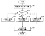
図2のフローチャートを参照して、図1のエンジンECU300で実行されるプログラムの制御構造について説明する。
A control structure of a program executed by
ステップ(以下、ステップをSと略す)100にて、エンジンECU300は、図3に示すようなマップを用いて筒内噴射用インジェクタ110の噴射比率(以下、「DI比率r」(0≦r≦1)と記載する)を計算する。このときに用いられるマップの詳細については後述する。
In step (hereinafter abbreviated as S) 100,
S110にて、エンジンECU300は、DI比率rが、1であるか、0であるか、0より大きく1より小さいのいずれであるかを判断する。DI比率rが1であると(S110にてr=1.0)、処理はS120へ移される。DI比率rが0であると(S110にてr=0)、処理はS130へ移される。DI比率rが0より大きく1より小さいと(S110にて0<r<1.0)、処理はS140へ移される。
In S110,
S120にて、エンジンECU300は、筒内噴射用インジェクタ110のみで燃料噴射をしている冷間時の進角補正量である冷間進角量を計算する。このとき、たとえば関数f(1)を用いて、冷間進角量=f(1)(THW)により算出される。なお、THWは、水温センサ380により検知されるエンジン10の冷却水の温度である。
In S120,
ここで、筒内噴射用インジェクタ110と吸気通路噴射用インジェクタ120とでは、インジェクタから噴射された燃料と空気との混合気の状態が全く異なる。特に、冷間時において、筒内噴射用インジェクタ110により高温の筒内に噴射される燃料と空気との混合気の状態、および、吸気通路噴射用インジェクタ120により低温の吸気通路に噴射される燃料と空気との混合気の状態が異なる。吸気通路噴射用インジェクタ120から噴射された燃料は、その霧化状態が不良で、霧化状態の良好でない燃料と空気との混合気の状態(均質性)が良好でないので燃焼速度が遅い。一方、筒内噴射用インジェクタ110から噴射された燃料は、その霧化状態が良好で、霧化状態の良好な燃料と空気との混合気の状態(均質性)が良好であって燃焼速度が速い。
Here, in-
関数f(1)(THW)は、DI比率r=1(筒内噴射用インジェクタ110からのみ燃料を噴射)の場合に適用される関数であって、冷間進角量が最も小さくなるような(基準点火時期から遅角側の点火時期になることを含む)関数として設定される。これは、筒内噴射用インジェクタ110から噴射された燃料と空気との混合気の均質性が良好であるので燃焼速度が早く、点火時期を最も遅らせても十分な燃焼期間を確保することができるためである。
The function f (1) (THW) is a function applied when the DI ratio r = 1 (fuel is injected only from the in-cylinder injector 110), and the cold advance angle is minimized. It is set as a function (including that the ignition timing is retarded from the reference ignition timing). This is because the homogeneity of the mixture of fuel and air injected from the in-
このような場合であっても、筒内噴射用インジェクタ110が燃料を噴射してから点火までの期間は短いため、燃料の霧化状態は良好であっても、均質性を確保するために十分な期間がない傾向である。このため、筒内噴射用インジェクタ110による燃料噴射から点火までの期間が短いことは混合気の均質性が良好でなくなるように作用する。このため、関数f(1)(THW)は、このような燃料噴射から点火までの時間を考慮して設定する場合も想定しうる。
Even in such a case, since the period from when the in-
S130にて、エンジンECU300は、吸気通路噴射用インジェクタ120のみで燃料噴射をしている冷間時の進角補正量である冷間進角量を計算する。このとき、たとえば関数f(2)を用いて、冷間補正量=f(2)(THW)により算出される。
In S130,
関数f(2)(THW)は、DI比率r=0(吸気通路噴射用インジェクタ120からのみ燃料を噴射)の場合に適用される関数であって、冷間進角量が最も大きくなるような関数として設定される。これは、吸気通路噴射用インジェクタ120から噴射された燃料と空気との混合気との均質性が良好でないので燃焼速度が遅いので点火時期を最も早めて十分な燃焼期間を確保するためである。
The function f (2) (THW) is a function applied when the DI ratio r = 0 (fuel is injected only from the intake manifold injector 120), and the cold advance angle is maximized. Set as a function. This is because the homogeneity of the fuel / air mixture injected from the
このような場合であっても、吸気通路噴射用インジェクタ120が燃料を噴射してから点火するまでの期間は長いので、燃料の霧化状態は良好でなくても、均質性を確保するために十分な時間がある傾向である。このため、吸気通路噴射用インジェクタ120による燃料噴射から点火までの期間が長いことは混合気の均質性が良好になるように作用する。このため、関数f(2)(THW)は、このような燃料噴射から点火までの時間を考慮して設定する場合も想定しうる。
Even in such a case, since the period from when the
S140にて、エンジンECU300は、筒内噴射用インジェクタ110と吸気通路噴射用インジェクタ120とで燃料噴射を分担している冷間時の進角補正量である冷間進角量を計算する。このとき、たとえば関数f(3)を用いて、冷間進角量=f(3)(THW,r)により算出される。なお、rはDI比率である。
In S140,
S150にて、エンジンECU300は、点火時期を計算する。このとき、点火時期は、たとえば関数gを用いて、点火時期=g(冷間進角量)により算出される。
In S150,
図3にエンジン10の回転数NEと負荷率KLとをパラメータとする筒内噴射用インジェクタ110の噴射比率(0≦DI比率r≦1)について説明する。
FIG. 3 illustrates the injection ratio (0 ≦ DI ratio r ≦ 1) of the in-
低回転数領域の高負荷領域においては、筒内噴射用インジェクタ110から噴射された燃料により形成される混合気のミキシングが良好ではなく、燃焼室内の混合気が不均質で燃焼が不安定になる傾向を有する。このためこの領域においてはDI比率rを低くして、燃焼室に投入されるまでに混合気が十分にミキシングされる吸気通路噴射用インジェクタ120による噴射比率(1−r)を大きくしている。
In the high load region of the low engine speed region, mixing of the air-fuel mixture formed by the fuel injected from the in-
高回転数領域の低負荷領域においては、筒内噴射用インジェクタ110から噴射された混合気を均質化しやすい。このため、DI比率rを高くする。筒内噴射用インジェクタ110から噴射された燃料は、燃焼室内で気化潜熱を伴い(燃焼室から熱を奪い)気化される。これにより、圧縮端での混合気の温度が下がり、対ノッキング性能が向上する。また、燃焼室の温度が下がるので、吸入効率が向上し高出力が見込める。さらに、燃焼室内に露出した筒内噴射用インジェクタ110の先端部が燃料で冷却されるので、筒内噴射用インジェクタ110の噴口にデポジットが付着することも抑制される。
In the low load region of the high rotation speed region, the air-fuel mixture injected from the in-
以上のような構造およびフローチャートに基づく、本実施の形態に係るエンジン10の動作について説明する。なお、以下の説明でエンジン冷却水温に変化がある場合とは、冷間から温間への過渡期であることを示す。
An operation of
<DI比率変化なし、エンジン冷却水温変化あり>
エンジン10が始動されると、通常は徐々にエンジン冷却水温が上昇する。すなわち、図4のA点に対応するエンジン冷却水温TH(1)から、B点に対応するエンジン冷却水温TH(2)に上昇する。この場合において、DI比率が計算され(S100)、DI比率rが変化していない時(たとえばr=0.7)には、DI比率rが0より大きく1より小さいと判断され(S110にて0<r<1.0)、関数f(3)を用いて、f(3)(THW,r)により冷間進角量が算出される(S140)。
<DI ratio unchanged, engine coolant temperature changed>
When the
図4のA点の場合、f(3)(TH(1),r)(r=0.7)により、冷間進角量が進角補正(1)として算出される。冷間進角量が進角補正(1)の状態でエンジン10が運転されて、エンジン冷却水温THWがTH(1)からTH(2)に上昇してB点に到達する。図4のB点の場合、f(3)(TH(2),r)(r=0.7)により、冷間進角量が進角補正(2)として算出される。すなわち、進角補正量については、進角補正(1)から進角補正(2)に、進角補正量変化分だけ下げられる。この進角補正量変化分は、{進角補正(1)−進角補正(2)}で与えられる。
In the case of point A in FIG. 4, the cold advance amount is calculated as advance angle correction (1) by f (3) (TH (1), r) (r = 0.7). The
<DI比率変化あり、エンジン冷却水温変化なし>
エンジン10が始動されても、車両の周囲の状態(特に温度状態)によっては、エンジン冷却水温が変化しない場合もある。このような場合であって、エンジン10の運転状態が変化してDI比率rが0.7から低下すると、すなわち、図4のA点に対応するエンジン冷却水温TH(1)のままで、r=0.7よりもDI比率rが小さいC点に状態が変化する(この逆でも構わない)。この場合において、DI比率が計算され(S100)、DI比率rが変化していても(たとえばr=0.7からr=0.5)、DI比率rが0より大きく1より小さいと判断され(S110にて0<r<1.0)、関数f(3)を用いて、f(3)(THW,r)により冷間進角量が算出される(S140)。
<DI ratio changed, engine coolant temperature not changed>
Even if the
図4のA点の場合、f(3)(TH(1),r)(r=0.7)により、冷間進角量が算出される。この状態でエンジン10が運転されて、エンジン冷却水温THWがTH(1)のままDI比率が低下してC点に到達する。図4のC点の場合、f(3)(TH(1),r)(r=0.5)により、冷間進角量が算出される。すなわち、進角補正量変化分だけ、点火時期が進角される。これは、筒内の温度よりもポートの温度が低いので、吸気通路噴射用インジェクタ120から噴射された燃料が霧化されにくいので、より大きく進角させることを示す。
In the case of point A in FIG. 4, the cold advance amount is calculated by f (3) (TH (1), r) (r = 0.7). In this state, the
<DI比率変化あり、エンジン冷却水温変化あり>
エンジン10が始動されて、エンジン冷却水温もDI比率rも変化する場合もある。このような場合には、図4のA点に対応するエンジン冷却水温TH(1)かつDI比率r=0.7の状態から、エンジン冷却水温TH(1)よりも高いTH(2)かつDI比率r=0.7よりもDI比率rが小さいD点に状態が変化する。この場合において、DI比率が計算され(S100)、DI比率rが変化していても(たとえばr=0.7からr=0.5)、DI比率rが0より大きく1より小さいと判断され(S110にて0<r<1.0)、関数f(3)を用いて、f(3)(THW,r)により冷間進角量が算出される(S140)。
<DI ratio change, engine coolant temperature change>
When the
図4のA点の場合、f(3)(TH(1),r)(r=0.7)により、冷間進角量が算出される。この状態でエンジン10が運転されて、エンジン冷却水温THWがTH(1)からTH(2)に変化するとともに、DI比率が低下してD点に到達する。図4のD点の場合、f(3)(TH(2),r)(r=0.5)により、冷間進角量が算出される。すなわち、進角補正量変化分だけ点火時期が変化される。これは、DI比率が0でもなく1でもないときには、冷間進角量はエンジン冷却水温とDI比率rとの関数で算出されるので、進角補正量の変化分もエンジン冷却水温の変化とDI比率rの変化に依存することを示す。
In the case of point A in FIG. 4, the cold advance amount is calculated by f (3) (TH (1), r) (r = 0.7). In this state, the
以上のようにして、冷間時、冷間時から温間時への過渡期において、進角量を、筒内噴射用インジェクタと吸気通路噴射用インジェクタとで燃料噴射を分担している場合には、エンジン冷却水温THWのみではなく、DI比率rを加えて、冷間進角量を算出するようにした。これにより、筒内とポートとで温度が異なってそれぞれにおける燃料の霧化の状態が異なっても、的確な点火時期まで進角させて燃焼状態を良好なものにすることができる。 As described above, in the case of cold, in the transitional period from cold to warm, the advance amount is shared between the fuel injector by the in-cylinder injector and the intake manifold injector Added the DI ratio r in addition to the engine coolant temperature THW to calculate the cold advance amount. As a result, even if the temperature is different between the cylinder and the port and the state of fuel atomization is different, the combustion state can be improved by advancing to an appropriate ignition timing.
また、以下のように3つのマップをエンジンECU300のROM320やRAM340に記憶するようにしてもよい。
Further, the three maps may be stored in the
第1のマップを、DI比率r=1(筒内噴射用インジェクタ110からのみ燃料を噴射)の場合に適用されるマップであって、点火時期を最も遅角側にする基本点火時期や点火時期を最も遅角側にする点火時期変動量のマップとして設定する。冷間時においても筒内噴射用インジェクタ110から燃料が噴射される筒内は高温であるので、噴射された燃料の霧化状態が良好で、霧化状態の良好な燃料と空気との混合気の均質性が良好であって、燃焼速度が速いので点火時期を遅らせても十分な燃焼時間を確保できる。さらに、燃焼速度による点火時期の制限が緩慢であるので、他の要因(たとえば触媒暖気、排気ガス浄化)により基本点火時期をさらに遅角させたり、進角させたりすることが可能になる。
The first map is a map that is applied when the DI ratio r = 1 (fuel is injected only from the in-cylinder injector 110), and the basic ignition timing and ignition timing that make the ignition timing the most retarded. Is set as a map of the ignition timing fluctuation amount which makes the most retarded. Even when it is cold, the cylinder in which the fuel is injected from the in-
第2のマップを、DI比率r=0(吸気通路噴射用インジェクタ120からのみ燃料を噴射)の場合に適用されるマップであって、点火時期を最も進角側にする基本点火時期や点火時期を最も進角側にする点火時期変動量のマップとして設定する。冷間時においては、吸気通路噴射用インジェクタ120から燃料が噴射される吸気通路は低温であるので、噴射された燃料の霧化状態が良好ではなく、霧化状態が良好ではない燃料と空気との混合気の均質性が良好ではなく燃焼速度が遅いので点火時期を早めて十分な燃焼期間を確保する必要がある。
The second map is a map applied when the DI ratio r = 0 (fuel is injected only from the intake manifold injector 120), and the basic ignition timing and ignition timing that make the ignition timing the most advanced side. Is set as a map of the ignition timing fluctuation amount with the most advanced side. In the cold state, since the intake passage through which the fuel is injected from the
第3のマップを、DI比率0<r<1(筒内噴射用インジェクタ110と吸気通路噴射用インジェクタ120とから燃料を噴射)の場合に適用されるマップであって、点火時期をDI比率rが高いほど遅角側にさせた基本点火時期や点火時期変動量のマップとして設定する。DI比率が高くなるにしたがって燃料の霧化状態が良好になり混合気の均質性が良好になり、燃焼速度が早くなるので、点火時期を遅らせる。
The third map is a map applied when the DI ratio is 0 <r <1 (fuel is injected from the in-
エンジンECU300は、このような基本点火時期や点火時期変動量について、3つのマップを予め準備しておいて、筒内噴射用インジェクタ110の分担比率であるDI比率rにより、基本点火時期マップや点火時期変動量マップを切り換えるように1つのマップを選択する。エンジンECU300は、選択されたマップに基づいて、基本点火時期を算出する。特に、第3のマップにおいては、DI比率rにより基本点火時期や点火時期変動量が変化するため、マップのみならず、そのマップにおいて設定された間を補間する関数を予め算出しておいて、その関数を記憶しておき、その関数で補間処理するようにしてもよい。
The
以上のようにして、3つのマップ(DI比率:r=1,r=0,0<r<1)を、DI比率rを用いて選択して、選択されたマップにより基本点火時期や点火時期変動量を算出するようにすることにより、DI比率rに対応させて適切な基本点火時期を算出することができる。このようにすると、DI比率rに応じて最適な基本点火時期を設定できるので、遅角過多による弊害や進角過多による弊害を発生させないようにすることができる。 As described above, three maps (DI ratio: r = 1, r = 0, 0 <r <1) are selected using the DI ratio r, and the basic ignition timing and ignition timing are selected according to the selected map. By calculating the fluctuation amount, an appropriate basic ignition timing can be calculated in correspondence with the DI ratio r. In this way, since the optimum basic ignition timing can be set according to the DI ratio r, it is possible to prevent the adverse effects caused by the excessive retardation and the adverse effects caused by the excessive advance angle.
<この制御装置が適用されるに適したエンジン(その1)>
以下、本実施の形態に係る制御装置が適用されるに適したエンジン(その1)について説明する。
<Engine suitable for application of this control apparatus (part 1)>
Hereinafter, an engine (part 1) suitable for application of the control device according to the present embodiment will be described.
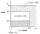
図5および図6を参照して、エンジン10の運転状態に対応させた情報である、筒内噴射用インジェクタ110と吸気通路噴射用インジェクタ120との噴き分け比率(以下、DI比率(r)とも記載する。)を表わすマップについて説明する。これらのマップは、エンジンECU300のROM320に記憶される。図5は、エンジン10の温間用マップであって、図6は、エンジン10の冷間用マップである。
Referring to FIGS. 5 and 6, the injection ratio of in-
図5および図6に示すように、これらのマップは、エンジン10の回転数を横軸にして、負荷率を縦軸にして、筒内噴射用インジェクタ110の分担比率がDI比率rとして百分率で示されている。
As shown in FIG. 5 and FIG. 6, these maps are shown in percentages where the
図5および図6に示すように、エンジン10の回転数と負荷率とに定まる運転領域ごとに、DI比率rが設定されている。「DI比率r=100%」とは、筒内噴射用インジェクタ110からのみ燃料噴射が行なわれる領域であることを意味し、「DI比率r=0%」とは、吸気通路噴射用インジェクタ120からのみ燃料噴射が行なわれる領域であることを意味する。「DI比率r≠0%」、「DI比率r≠100%」および「0%<DI比率r<100%」とは、筒内噴射用インジェクタ110と吸気通路噴射用インジェクタ120とで燃料噴射が分担して行なわれる領域であることを意味する。なお、概略的には、筒内噴射用インジェクタ110は、出力性能の上昇に寄与し、吸気通路噴射用インジェクタ120は、混合気の均一性に寄与する。このような特性の異なる2種類のインジェクタを、エンジン10の回転数と負荷率とで使い分けることにより、エンジン10が通常運転状態(たとえば、アイドル時の触媒暖気時が、通常運転状態以外の非通常運転状態の一例であるといえる)である場合には、均質燃焼のみが行なわれるようにしている。
As shown in FIGS. 5 and 6, the DI ratio r is set for each operation region determined by the rotational speed and load factor of the
さらに、これらの図5および図6に示すように、温間時のマップと冷間時のマップとに分けて、筒内噴射用インジェクタ110と吸気通路噴射用インジェクタ120のDI分担率rを規定した。エンジン10の温度が異なると、筒内噴射用インジェクタ110および吸気通路噴射用インジェクタ120の制御領域が異なるように設定されたマップを用いて、エンジン10の温度を検知して、エンジン10の温度が予め定められた温度しきい値以上であると図5の温間時のマップを選択して、そうではないと図6に示す冷間時のマップを選択する。それぞれ選択されたマップに基づいて、エンジン10の回転数と負荷率とに基づいて、筒内噴射用インジェクタ110および/または吸気通路噴射用インジェクタ120を制御する。
Further, as shown in FIG. 5 and FIG. 6, the DI share ratio r of the in-
図5および図6に設定されるエンジン10の回転数と負荷率について説明する。図5のNE(1)は2500〜2700rpmに設定され、KL(1)は30〜50%、KL(2)は60〜90%に設定されている。また、図6のNE(3)は2900〜3100rpmに設定されている。すなわち、NE(1)<NE(3)である。その他、図5のNE(2)や、図6のKL(3)、KL(4)も適宜設定されている。
The engine speed and load factor of
図5および図6を比較すると、図5に示す温間用マップのNE(1)よりも図6に示す冷間用マップのNE(3)の方が高い。これは、エンジン10の温度が低いほど、吸気通路噴射用インジェクタ120の制御領域が高いエンジン回転数の領域まで拡大されるということを示す。すなわち、エンジン10が冷えている状態であるので、(たとえ、筒内噴射用インジェクタ110から燃料を噴射しなくても)筒内噴射用インジェクタ110の噴口にデポジットが堆積しにくい。このため、吸気通路噴射用インジェクタ120を使って燃料を噴射する領域を拡大するように設定され、均質性を向上させることができる。
When FIG. 5 and FIG. 6 are compared, NE (3) of the map for cold shown in FIG. 6 is higher than NE (1) of the map for warm shown in FIG. This indicates that as the temperature of the
図5および図6を比較すると、エンジン10の回転数が、温間用マップにおいてはNE(1)以上の領域において、冷間用マップにおいてはNE(3)以上の領域において、「DI比率r=100%」である。また、負荷率が、温間用マップにおいてはKL(2)以上の領域において、冷間用マップにおいてはKL(4)以上の領域において、「DI比率r=100%」である。これは、予め定められた高エンジン回転数領域では筒内噴射用インジェクタ110のみが使用されること、予め定められた高エンジン負荷領域では筒内噴射用インジェクタ110のみが使用されるということを示す。すなわち、高回転領域や高負荷領域においては、筒内噴射用インジェクタ110のみで燃料を噴射しても、エンジン10の回転数や負荷が高く吸気量が多いので筒内噴射用インジェクタ110のみでも混合気を均質化しやすいためである。このようにすると、筒内噴射用インジェクタ110から噴射された燃料は燃焼室内で気化潜熱を伴い(燃焼室から熱を奪い)気化される。これにより、圧縮端での混合気の温度が下がる。これにより対ノッキング性能が向上する。また、燃焼室の温度が下がるので、吸入効率が向上し高出力が見込める。
Comparing FIG. 5 and FIG. 6, in the region where the
図5に示す温間マップでは、負荷率KL(1)以下では、筒内噴射用インジェクタ110のみが用いられる。これは、エンジン10の温度が高いときであって、予め定められた低負荷領域では筒内噴射用インジェクタ110のみが使用されるということを示す。これは、温間時においてはエンジン10が暖まった状態であるので、筒内噴射用インジェクタ110の噴口にデポジットが堆積しやすい。しかしながら、筒内噴射用インジェクタ110を使って燃料を噴射することにより噴口温度を低下させることができるので、デポジットの堆積を回避することも考えられ、また、筒内噴射用インジェクタの最小燃料噴射量を確保して、筒内噴射用インジェクタ110を閉塞させないことも考えられ、このために、筒内噴射用インジェクタ110を用いた領域としている。
In the warm map shown in FIG. 5, only the in-
図5および図6を比較すると、図6の冷間用マップにのみ「DI比率r=0%」の領域が存在する。これは、エンジン10の温度が低いときであって、予め定められた低負荷領域(KL(3)以下)では吸気通路噴射用インジェクタ120のみが使用されるということを示す。これはエンジン10が冷えていてエンジン10の負荷が低く吸気量も低いため燃料が霧化しにくい。このような領域においては筒内噴射用インジェクタ110による燃料噴射では良好な燃焼が困難であるため、また、特に低負荷および低回転数の領域では筒内噴射用インジェクタ110を用いた高出力を必要としないため、筒内噴射用インジェクタ110を用いないで、吸気通路噴射用インジェクタ120のみを用いる。
Comparing FIG. 5 and FIG. 6, the region of “DI ratio r = 0%” exists only in the cold map of FIG. 6. This indicates that when the temperature of the
また、通常運転時以外の場合、エンジン10がアイドル時の触媒暖気時の場合(非通常運転状態であるとき)、成層燃焼を行なうように筒内噴射用インジェクタ110が制御される。このような触媒暖気運転中にのみ成層燃焼させることで、触媒暖気を促進させ、排気エミッションの向上を図る。
In addition, in the case other than the normal operation, the in-
<この制御装置が適用されるに適したエンジン(その2)>
以下、本実施の形態に係る制御装置が適用されるに適したエンジン(その2)について説明する。なお、以下のエンジン(その2)の説明において、エンジン(その1)と同じ説明については、ここでは繰り返さない。
<Engine suitable for application of this control device (part 2)>
Hereinafter, an engine (part 2) suitable for application of the control device according to the present embodiment will be described. In the following description of the engine (part 2), the same description as the engine (part 1) will not be repeated here.
図7および図8を参照して、エンジン10の運転状態に対応させた情報である、筒内噴射用インジェクタ110と吸気通路噴射用インジェクタ120との噴き分け比率を表わすマップについて説明する。これらのマップは、エンジンECU300のROM320に記憶される。図7は、エンジン10の温間用マップであって、図8は、エンジン10の冷間用マップである。
With reference to FIGS. 7 and 8, a map representing the injection ratio of in-
図7および図8を比較すると、以下の点で図5および図6と異なる。エンジン10の回転数が、温間用マップにおいてはNE(1)以上の領域において、冷間用マップにおいてはNE(3)以上の領域において、「DI比率r=100%」である。また、負荷率が、温間用マップにおいては低回転数領域を除くKL(2)以上の領域において、冷間用マップにおいては低回転数領域を除くKL(4)以上の領域において、「DI比率r=100%」である。これは、予め定められた高エンジン回転数領域では筒内噴射用インジェクタ110のみが使用されること、予め定められた高エンジン負荷領域では筒内噴射用インジェクタ110のみが使用される領域が多いことを示す。しかしながら、低回転数領域の高負荷領域においては、筒内噴射用インジェクタ110から噴射された燃料により形成される混合気のミキシングが良好ではなく、燃焼室内の混合気が不均質で燃焼が不安定になる傾向を有する。このため、このような問題が発生しない高回転数領域へ移行するに伴い筒内噴射用インジェクタの噴射比率を増大させるようにしている。また、このような問題が発生する高負荷領域へ移行するに伴い筒内噴射用インジェクタ110の噴射比率を減少させるようにしている。これらのDI比率rの変化を図7および図8に十字の矢印で示す。このようにすると、燃焼が不安定であることに起因するエンジンの出力トルクの変動を抑制することができる。なお、これらのことは、予め定められた低回転数領域へ移行するに伴い筒内噴射用インジェクタ110の噴射比率を減少させることや、予め定められた低負荷領域へ移行するに伴い筒内噴射用インジェクタ110の噴射比率を増大させることと、略等価であることを確認的に記載する。また、このような領域(図7および図8で十字の矢印が記載された領域)以外の領域であって筒内噴射用インジェクタ110のみで燃料を噴射している領域(高回転側、低負荷側)においては、筒内噴射用インジェクタ110のみでも混合気を均質化しやすい。このようにすると、筒内噴射用インジェクタ110から噴射された燃料は燃焼室内で気化潜熱を伴い(燃焼室から熱を奪い)気化される。これにより、圧縮端での混合気の温度が下がる。これにより対ノッキング性能が向上する。また、燃焼室の温度が下がるので、吸入効率が向上し高出力が見込める。
7 and 8 differ from FIGS. 5 and 6 in the following points. The rotational speed of the
なお、図5〜図8を用いて説明したこのエンジン10においては、均質燃焼は筒内噴射用インジェクタ110の燃料噴射タイミングを吸気行程とすることにより、成層燃焼は筒内噴射用インジェクタ110の燃料噴射タイミングを圧縮行程とすることにより実現できる。すなわち、筒内噴射用インジェクタ110の燃料噴射タイミングを圧縮行程とすることで、点火プラグ周りにリッチ混合気が偏在させることにより燃焼室全体としてはリーンな混合気に着火する成層燃焼を実現することができる。また、筒内噴射用インジェクタ110の燃料噴射タイミングを吸気行程としても点火プラグ周りにリッチ混合気を偏在させることができれば、吸気行程噴射であっても成層燃焼を実現できる。
In the
また、ここでいう成層燃焼には、成層燃焼と以下に示す弱成層燃焼の双方を含むものである。弱成層燃焼とは、吸気通路噴射用インジェクタ120を吸気行程で燃料噴射して燃焼室全体にリーンで均質な混合気を生成して、さらに筒内噴射用インジェクタ110を圧縮行程で燃料噴射して点火プラグ周りにリッチな混合気を生成して、燃焼状態の向上を図るものである。このような弱成層燃焼は触媒暖気時に好ましい。これは、以下の理由による。すなわち、触媒暖気時には高温の燃焼ガスを触媒に到達させるために点火時期を大幅に遅角させ、かつ良好な燃焼状態(アイドル状態)を維持する必要がある。また、ある程度の燃料量を供給する必要がある。これを成層燃焼で行なおうとしても燃料量が少ないという問題があり、これを均質燃焼で行なおうとしても良好な燃焼を維持するために遅角量が成層燃焼に比べて小さいという問題がある。このような観点から、上述した弱成層燃焼を触媒暖気時に用いることが好ましいが、成層燃焼および弱成層燃焼のいずれであっても構わない。
Further, the stratified combustion here includes both stratified combustion and weakly stratified combustion described below. In the weak stratified combustion, the
また、図5〜図8を用いて説明したエンジンにおいては、筒内噴射用インジェクタ110による燃料噴射のタイミングは、以下のような理由により、圧縮行程で行なうことが好ましい。ただし、上述したエンジン10は、基本的な大部分の領域には(触媒暖気時にのみに行なわれる、吸気通路噴射用インジェクタ120を吸気行程噴射させ、筒内噴射用インジェクタ110を圧縮行程噴射させる弱成層燃焼領域以外を基本的な領域という)、筒内噴射用インジェクタ110による燃料噴射のタイミングは、吸気行程である。しかしながら、以下に示す理由があるので、燃焼安定化を目的として一時的に筒内噴射用インジェクタ110の燃料噴射タイミングを圧縮行程噴射とするようにしてもよい。
In the engine described with reference to FIGS. 5 to 8, the fuel injection timing by the in-
筒内噴射用インジェクタ110からの燃料噴射時期を圧縮工程中とすることで、筒内温度がより高い時期において、燃料噴射により混合気が冷却される。冷却効果が高まるので、対ノック性を改善することができる。さらに、筒内噴射用インジェクタ110からの燃料噴射時期を圧縮工程中とすると、燃料噴射から点火時期までの時間が短いことから噴霧による気流の強化を実現でき、燃焼速度を上昇させることができる。これらの対ノック性の向上と燃焼速度の上昇とから、燃焼変動を回避して、燃焼安定性を向上させることができる。
By setting the fuel injection timing from the in-
なお、上述したフローチャートのS150においては、このフローチャートが実行される毎にエンジン10の作動状態から基本点火時期を算出しておいて、その基本点火時期に対して冷間進角量分だけを補正するような関数gを用いて点火時期を算出するようにしてもよい。
In S150 of the flowchart described above, the basic ignition timing is calculated from the operating state of the
さらに、エンジン10の温度によらず(すなわち、温間時および冷間時のいずれの場合であっても)、オフアイドル時(アイドルスイッチがオフの場合、アクセルペダルが踏まれている場合)には、図5または図7に示す温間マップを用いるようにしてもよい(冷間温間を問わず、低負荷領域において筒内噴射用インジェクタ110を用いる)。
Furthermore, regardless of the temperature of the engine 10 (that is, whether the engine is warm or cold), it is off-idle (when the idle switch is off or the accelerator pedal is depressed). May use the warm map shown in FIG. 5 or 7 (the in-
今回開示された実施の形態はすべての点で例示であって制限的なものではないと考えられるべきである。本発明の範囲は上記した説明ではなくて特許請求の範囲によって示され、特許請求の範囲と均等の意味および範囲内でのすべての変更が含まれることが意図される。 The embodiment disclosed this time should be considered as illustrative in all points and not restrictive. The scope of the present invention is defined by the terms of the claims, rather than the description above, and is intended to include any modifications within the scope and meaning equivalent to the terms of the claims.
10 エンジン、20 インテークマニホールド、30 サージタンク、40 吸気ダクト、42 エアフローメータ、50 エアクリーナ、60 電動モータ、70 スロットルバルブ、80 エキゾーストマニホールド、90 三元触媒コンバータ、100 アクセルペダル、110 筒内噴射用インジェクタ、112 気筒、120 吸気通路噴射用インジェクタ、130 燃料分配管、140 逆止弁、150 高圧燃料ポンプ、152 電磁スピル弁、160 燃料分配管(低圧側)、170 燃料圧レギュレータ、180 低圧燃料ポンプ、190 燃料フィルタ、200 燃料タンク、300 エンジンECU、310 双方向性バス、320 ROM、330 RAM、340 CPU、350 入力ポート、360 出力ポート、370,390,410,430,450 A/D変換器、380 水温センサ、400 燃料圧センサ、420 空燃比センサ、440 アクセル開度センサ、460 回転数センサ。 10 engine, 20 intake manifold, 30 surge tank, 40 air intake duct, 42 air flow meter, 50 air cleaner, 60 electric motor, 70 throttle valve, 80 exhaust manifold, 90 three-way catalytic converter, 100 accelerator pedal, 110 in-cylinder injector , 112 cylinder, 120 Injector injector, 130 Fuel distribution pipe, 140 Check valve, 150 High pressure fuel pump, 152 Electromagnetic spill valve, 160 Fuel distribution pipe (low pressure side), 170 Fuel pressure regulator, 180 Low pressure fuel pump, 190 fuel filter, 200 fuel tank, 300 engine ECU, 310 bidirectional bus, 320 ROM, 330 RAM, 340 CPU, 350 input port, 360 output port, 370, 39 , 410,430,450 A / D converter, 380 a water temperature sensor, 400 a fuel pressure sensor, 420 an air-fuel ratio sensor, 440 an accelerator opening sensor, 460 rpm sensor.
Claims (15)
前記内燃機関に要求される条件に基づいて算出された比率で、前記第1の燃料噴射手段と前記第2の燃料噴射手段とで分担して燃料を噴射するように、燃料噴射手段を制御するための制御手段と、
前記内燃機関の温度を検知するための検知手段と、
点火時期を変化させるように点火装置を制御するための点火時期制御手段とを含み、
前記点火時期制御手段は、前記内燃機関の冷間時における進角量を、前記比率および前記温度に基づいて算出して、算出された進角量に基づいて点火時期を変化させるように前記点火装置を制御するための手段を含み、
前記点火時期制御手段は、前記第1の燃料噴射手段の比率が高いほど、前記進角量が小さくなるように算出するための手段を含む、内燃機関の制御装置。 A control device for an internal combustion engine comprising a first fuel injection means for injecting fuel into a cylinder and a second fuel injection means for injecting fuel into an intake passage,
The fuel injection means is controlled so that fuel is injected between the first fuel injection means and the second fuel injection means at a ratio calculated based on conditions required for the internal combustion engine. Control means for,
Detecting means for detecting the temperature of the internal combustion engine;
Ignition timing control means for controlling the ignition device so as to change the ignition timing,
The ignition timing control means calculates an advance amount when the internal combustion engine is cold based on the ratio and the temperature, and changes the ignition timing based on the calculated advance amount. Including means for controlling the device;
The control device for an internal combustion engine, wherein the ignition timing control means includes means for calculating the advance amount so that the higher the ratio of the first fuel injection means, the smaller the advance amount .
前記内燃機関に要求される条件に基づいて算出された比率で、前記第1の燃料噴射手段と前記第2の燃料噴射手段とで分担して燃料を噴射するように、燃料噴射手段を制御するための制御手段と、
前記内燃機関の温度を検知するための検知手段と、
基本点火時期を算出するための算出手段と、
進角補正量を用いて前記基本点火時期を変化させるように点火装置を制御するための点火時期制御手段とを含み、
前記点火時期制御手段は、前記内燃機関の冷間時における進角補正量を、前記比率および前記温度に基づいて算出して、算出された進角補正量を用いて前記基本点火時期を変化させるように前記点火装置を制御するための手段を含み、
前記点火時期制御手段は、前記第1の燃料噴射手段の比率が高いほど、前記進角量が小さくなるように算出するための手段を含む、内燃機関の制御装置。 A control device for an internal combustion engine comprising a first fuel injection means for injecting fuel into a cylinder and a second fuel injection means for injecting fuel into an intake passage,
The fuel injection means is controlled so that fuel is injected between the first fuel injection means and the second fuel injection means at a ratio calculated based on conditions required for the internal combustion engine. Control means for,
Detecting means for detecting the temperature of the internal combustion engine;
A calculation means for calculating the basic ignition timing;
Ignition timing control means for controlling the ignition device to change the basic ignition timing using an advance correction amount,
The ignition timing control means calculates an advance angle correction amount when the internal combustion engine is cold based on the ratio and the temperature, and changes the basic ignition timing using the calculated advance angle correction amount. Means for controlling the ignition device as
The control device for an internal combustion engine, wherein the ignition timing control means includes means for calculating the advance amount so that the higher the ratio of the first fuel injection means, the smaller the advance amount .
前記内燃機関に要求される条件に基づいて算出された比率で、前記第1の燃料噴射手段と前記第2の燃料噴射手段とで分担して燃料を噴射するように、燃料噴射手段を制御するための制御手段と、The fuel injection means is controlled so that fuel is injected between the first fuel injection means and the second fuel injection means at a ratio calculated based on conditions required for the internal combustion engine. Control means for,
前記内燃機関の温度を検知するための検知手段と、Detecting means for detecting the temperature of the internal combustion engine;
点火時期を変化させるように点火装置を制御するための点火時期制御手段とを含み、Ignition timing control means for controlling the ignition device so as to change the ignition timing,
前記点火時期制御手段は、前記内燃機関の冷間時における進角量を、前記比率および前記温度に基づいて算出して、算出された進角量に基づいて点火時期を変化させるように前記点火装置を制御するための手段を含み、The ignition timing control means calculates an advance amount when the internal combustion engine is cold based on the ratio and the temperature, and changes the ignition timing based on the calculated advance amount. Including means for controlling the device;
前記点火時期制御手段は、前記第2の燃料噴射手段の比率が高いほど、前記進角量が大きくなるように算出するための手段を含む、内燃機関の制御装置。The control device for an internal combustion engine, wherein the ignition timing control means includes means for calculating the advance amount so that the ratio of the second fuel injection means is higher.
前記内燃機関に要求される条件に基づいて算出された比率で、前記第1の燃料噴射手段と前記第2の燃料噴射手段とで分担して燃料を噴射するように、燃料噴射手段を制御するための制御手段と、The fuel injection means is controlled so that fuel is injected between the first fuel injection means and the second fuel injection means at a ratio calculated based on conditions required for the internal combustion engine. Control means for,
前記内燃機関の温度を検知するための検知手段と、Detecting means for detecting the temperature of the internal combustion engine;
基本点火時期を算出するための算出手段と、A calculation means for calculating the basic ignition timing;
進角補正量を用いて前記基本点火時期を変化させるように点火装置を制御するための点火時期制御手段とを含み、Ignition timing control means for controlling the ignition device to change the basic ignition timing using an advance correction amount,
前記点火時期制御手段は、前記内燃機関の冷間時における進角補正量を、前記比率および前記温度に基づいて算出して、算出された進角補正量を用いて前記基本点火時期を変化させるように前記点火装置を制御するための手段を含み、The ignition timing control means calculates an advance angle correction amount when the internal combustion engine is cold based on the ratio and the temperature, and changes the basic ignition timing using the calculated advance angle correction amount. Means for controlling the ignition device as
前記点火時期制御手段は、前記第2の燃料噴射手段の比率が高いほど、前記進角量が大きくなるように算出するための手段を含む、内燃機関の制御装置。The control device for an internal combustion engine, wherein the ignition timing control means includes means for calculating the advance amount so that the ratio of the second fuel injection means is higher.
前記内燃機関に要求される条件に基づいて算出された、一方の燃料噴射手段による燃料噴射が停止する場合を含む比率で、前記第1の燃料噴射手段と前記第2の燃料噴射手段とで分担して燃料を噴射するように、燃料噴射手段を制御するための制御手段と、
前記内燃機関の温度を検知するための検知手段と、
基本点火時期および冷間時の点火時期変動量を記憶するための記憶手段と、
前記基本点火時期から前記点火時期変動量の分だけ点火時期を変動させて点火装置を制御するための点火時期制御手段とを含み、
前記記憶手段は、前記温度および前記比率に基づいて算出された前記内燃機関の冷間時における点火時期変動量を記憶するための手段を含み、
前記記憶手段は、前記第1の燃料噴射手段の比率が高いほど遅角側に設定された前記点火時期変動量を記憶するための手段を含む、内燃機関の制御装置。 A control device for an internal combustion engine comprising a first fuel injection means for injecting fuel into a cylinder and a second fuel injection means for injecting fuel into an intake passage,
The first fuel injection means and the second fuel injection means share the ratio calculated based on the conditions required for the internal combustion engine, including the case where the fuel injection by one fuel injection means stops. And a control means for controlling the fuel injection means so as to inject the fuel,
Detecting means for detecting the temperature of the internal combustion engine;
Storage means for storing basic ignition timing and cold ignition timing fluctuation amount;
Ignition timing control means for controlling the ignition device by changing the ignition timing from the basic ignition timing by the ignition timing fluctuation amount,
The storage means includes means for storing an ignition timing fluctuation amount when the internal combustion engine is cold, which is calculated based on the temperature and the ratio,
The control device for an internal combustion engine, wherein the storage means includes means for storing the ignition timing fluctuation amount that is set to the retard side as the ratio of the first fuel injection means is higher .
前記内燃機関に要求される条件に基づいて算出された、一方の燃料噴射手段による燃料噴射が停止する場合を含む比率で、前記第1の燃料噴射手段と前記第2の燃料噴射手段とで分担して燃料を噴射するように、燃料噴射手段を制御するための制御手段と、
前記内燃機関の温度を検知するための検知手段と、
基本点火時期および冷間時の点火時期変動量を記憶するための記憶手段と、
前記基本点火時期から前記点火時期変動量の分だけ点火時期を変動させて点火装置を制御するための点火時期制御手段とを含み、
前記記憶手段は、前記温度および前記比率に基づいて算出された前記内燃機関の冷間時における点火時期変動量を記憶するための手段を含み、
前記記憶手段は、前記第2の燃料噴射手段の比率が高いほど進角側に設定された前記点火時期変動量を記憶するための手段を含む、内燃機関の制御装置。 A control device for an internal combustion engine comprising a first fuel injection means for injecting fuel into a cylinder and a second fuel injection means for injecting fuel into an intake passage,
The first fuel injection means and the second fuel injection means share the ratio calculated based on the conditions required for the internal combustion engine, including the case where the fuel injection by one fuel injection means stops. And a control means for controlling the fuel injection means so as to inject the fuel,
Detecting means for detecting the temperature of the internal combustion engine;
Storage means for storing basic ignition timing and cold ignition timing fluctuation amount;
Ignition timing control means for controlling the ignition device by changing the ignition timing from the basic ignition timing by the ignition timing fluctuation amount,
The storage means includes means for storing an ignition timing fluctuation amount when the internal combustion engine is cold, which is calculated based on the temperature and the ratio,
The control device for an internal combustion engine, wherein the storage means includes means for storing the ignition timing fluctuation amount set to an advance side as the ratio of the second fuel injection means is higher .
前記第2の燃料噴射手段は、吸気通路用インジェクタである、請求項1〜14のいずれかに記載の内燃機関の制御装置。 The first fuel injection means is an in-cylinder injector,
It said second fuel injection means is an intake manifold injector, the control apparatus for an internal combustion engine according to any of claims 1-14.
Priority Applications (5)
| Application Number | Priority Date | Filing Date | Title |
|---|---|---|---|
| JP2005078461A JP4462079B2 (en) | 2004-11-11 | 2005-03-18 | Control device for internal combustion engine |
| KR1020077013123A KR100872012B1 (en) | 2004-11-11 | 2005-11-07 | Control apparatus for internal combustion engine |
| EP05803286A EP1812702B1 (en) | 2004-11-11 | 2005-11-07 | Control apparatus for internal combustion engine |
| PCT/JP2005/020769 WO2006051925A1 (en) | 2004-11-11 | 2005-11-07 | Control apparatus for internal combustion engine |
| US11/268,597 US7216626B2 (en) | 2004-11-11 | 2005-11-08 | Control apparatus for internal combustion engine |
Applications Claiming Priority (2)
| Application Number | Priority Date | Filing Date | Title |
|---|---|---|---|
| JP2004328143 | 2004-11-11 | ||
| JP2005078461A JP4462079B2 (en) | 2004-11-11 | 2005-03-18 | Control device for internal combustion engine |
Publications (3)
| Publication Number | Publication Date |
|---|---|
| JP2006161799A JP2006161799A (en) | 2006-06-22 |
| JP2006161799A5 JP2006161799A5 (en) | 2008-04-17 |
| JP4462079B2 true JP4462079B2 (en) | 2010-05-12 |
Family
ID=35500982
Family Applications (1)
| Application Number | Title | Priority Date | Filing Date |
|---|---|---|---|
| JP2005078461A Expired - Fee Related JP4462079B2 (en) | 2004-11-11 | 2005-03-18 | Control device for internal combustion engine |
Country Status (5)
| Country | Link |
|---|---|
| US (1) | US7216626B2 (en) |
| EP (1) | EP1812702B1 (en) |
| JP (1) | JP4462079B2 (en) |
| KR (1) | KR100872012B1 (en) |
| WO (1) | WO2006051925A1 (en) |
Families Citing this family (17)
| Publication number | Priority date | Publication date | Assignee | Title |
|---|---|---|---|---|
| JP2006046084A (en) * | 2004-07-30 | 2006-02-16 | Toyota Motor Corp | Ignition timing controller for internal combustion engine |
| JP4487735B2 (en) * | 2004-11-11 | 2010-06-23 | トヨタ自動車株式会社 | Control device for internal combustion engine |
| JP2006183548A (en) * | 2004-12-27 | 2006-07-13 | Nippon Soken Inc | Control device for internal combustion engine |
| CA2602060C (en) * | 2005-03-18 | 2011-05-17 | Toyota Jidosha Kabushiki Kaisha | Internal combustion engine provided with double system of fuel injection |
| US20090241905A1 (en) * | 2006-03-29 | 2009-10-01 | Denso Corporation | Mount structure of fuel injection valve and fuel injection system |
| EP1860310B1 (en) * | 2006-05-23 | 2015-08-12 | Delphi International Operations Luxembourg S.à r.l. | Method of operating a fuel injector |
| JP4238890B2 (en) | 2006-07-24 | 2009-03-18 | トヨタ自動車株式会社 | Fuel injection control device for internal combustion engine |
| DE102008044242A1 (en) * | 2008-12-01 | 2010-06-02 | Robert Bosch Gmbh | Internal combustion engine |
| US8347862B2 (en) * | 2009-12-23 | 2013-01-08 | Ford Global Technologies, Llc | System and method for injecting fuel to a gaseous fueled engine |
| US9303577B2 (en) | 2012-12-19 | 2016-04-05 | Ford Global Technologies, Llc | Method and system for engine cold start and hot start control |
| US11078860B2 (en) * | 2013-03-11 | 2021-08-03 | Wayne State University | Predictive correction in internal combustion engines |
| US9255541B2 (en) | 2013-04-01 | 2016-02-09 | Ford Global Technologies, Llc | Method and system for engine control |
| US9297329B2 (en) | 2013-04-01 | 2016-03-29 | Ford Global Technologies, Llc | Method and system for engine control |
| US9435287B2 (en) | 2014-02-25 | 2016-09-06 | Ford Global Technologies, Llc | Method for fuel injection control |
| US9404435B2 (en) * | 2014-12-01 | 2016-08-02 | Ford Global Technologies, Llc | Methods and systems for adjusting fuel injector operation |
| JP6554863B2 (en) * | 2015-03-30 | 2019-08-07 | 三菱自動車工業株式会社 | Engine control device |
| JP6308166B2 (en) * | 2015-04-28 | 2018-04-11 | トヨタ自動車株式会社 | Control device for internal combustion engine |
Family Cites Families (3)
| Publication number | Priority date | Publication date | Assignee | Title |
|---|---|---|---|---|
| JP2001020837A (en) * | 1999-07-07 | 2001-01-23 | Nissan Motor Co Ltd | Fuel injection control device for engine |
| US6516774B2 (en) | 2000-05-08 | 2003-02-11 | Cummins Inc. | Premixed charge compression ignition engine with variable speed SOC control and method of operation |
| JP2004308510A (en) * | 2003-04-04 | 2004-11-04 | Toyota Motor Corp | Internal combustion engine detecting failure of compression ratio change mechanism for control |
-
2005
- 2005-03-18 JP JP2005078461A patent/JP4462079B2/en not_active Expired - Fee Related
- 2005-11-07 EP EP05803286A patent/EP1812702B1/en not_active Ceased
- 2005-11-07 WO PCT/JP2005/020769 patent/WO2006051925A1/en active Application Filing
- 2005-11-07 KR KR1020077013123A patent/KR100872012B1/en active IP Right Grant
- 2005-11-08 US US11/268,597 patent/US7216626B2/en active Active
Also Published As
| Publication number | Publication date |
|---|---|
| KR100872012B1 (en) | 2008-12-05 |
| US7216626B2 (en) | 2007-05-15 |
| WO2006051925A1 (en) | 2006-05-18 |
| JP2006161799A (en) | 2006-06-22 |
| EP1812702B1 (en) | 2012-09-19 |
| EP1812702A1 (en) | 2007-08-01 |
| US20060096575A1 (en) | 2006-05-11 |
| KR20070086023A (en) | 2007-08-27 |
Similar Documents
| Publication | Publication Date | Title |
|---|---|---|
| JP4462079B2 (en) | Control device for internal combustion engine | |
| JP4487735B2 (en) | Control device for internal combustion engine | |
| US7198031B2 (en) | Control device of internal combustion engine | |
| JP4643323B2 (en) | Control device for internal combustion engine | |
| US7159567B2 (en) | Control apparatus for internal combustion engine | |
| JP4453625B2 (en) | Control device for internal combustion engine | |
| JP4470773B2 (en) | Control device for internal combustion engine | |
| JP2006258017A (en) | Control device of internal combustion engine | |
| JP2006258009A (en) | Control device of internal combustion engine | |
| JP4449706B2 (en) | Control device for internal combustion engine | |
| JP4453524B2 (en) | Control device for internal combustion engine | |
| JP4581889B2 (en) | Engine control device | |
| JP2010065705A (en) | Control device for internal combustion engine |
Legal Events
| Date | Code | Title | Description |
|---|---|---|---|
| A521 | Written amendment |
Free format text: JAPANESE INTERMEDIATE CODE: A523 Effective date: 20080229 |
|
| A621 | Written request for application examination |
Free format text: JAPANESE INTERMEDIATE CODE: A621 Effective date: 20080229 |
|
| A131 | Notification of reasons for refusal |
Free format text: JAPANESE INTERMEDIATE CODE: A131 Effective date: 20090707 |
|
| A02 | Decision of refusal |
Free format text: JAPANESE INTERMEDIATE CODE: A02 Effective date: 20090929 |
|
| A521 | Written amendment |
Free format text: JAPANESE INTERMEDIATE CODE: A523 Effective date: 20091225 |
|
| A911 | Transfer to examiner for re-examination before appeal (zenchi) |
Free format text: JAPANESE INTERMEDIATE CODE: A911 Effective date: 20100106 |
|
| TRDD | Decision of grant or rejection written | ||
| A01 | Written decision to grant a patent or to grant a registration (utility model) |
Free format text: JAPANESE INTERMEDIATE CODE: A01 Effective date: 20100126 |
|
| A01 | Written decision to grant a patent or to grant a registration (utility model) |
Free format text: JAPANESE INTERMEDIATE CODE: A01 |
|
| A61 | First payment of annual fees (during grant procedure) |
Free format text: JAPANESE INTERMEDIATE CODE: A61 Effective date: 20100208 |
|
| FPAY | Renewal fee payment (event date is renewal date of database) |
Free format text: PAYMENT UNTIL: 20130226 Year of fee payment: 3 |
|
| R151 | Written notification of patent or utility model registration |
Ref document number: 4462079 Country of ref document: JP Free format text: JAPANESE INTERMEDIATE CODE: R151 |
|
| FPAY | Renewal fee payment (event date is renewal date of database) |
Free format text: PAYMENT UNTIL: 20130226 Year of fee payment: 3 |
|
| FPAY | Renewal fee payment (event date is renewal date of database) |
Free format text: PAYMENT UNTIL: 20140226 Year of fee payment: 4 |
|
| LAPS | Cancellation because of no payment of annual fees |