EP1808614A1 - Mechanical brake actuator - Google Patents
Mechanical brake actuator Download PDFInfo
- Publication number
- EP1808614A1 EP1808614A1 EP07290035A EP07290035A EP1808614A1 EP 1808614 A1 EP1808614 A1 EP 1808614A1 EP 07290035 A EP07290035 A EP 07290035A EP 07290035 A EP07290035 A EP 07290035A EP 1808614 A1 EP1808614 A1 EP 1808614A1
- Authority
- EP
- European Patent Office
- Prior art keywords
- strut
- clip
- brake
- brake lever
- connecting pin
- Prior art date
- Legal status (The legal status is an assumption and is not a legal conclusion. Google has not performed a legal analysis and makes no representation as to the accuracy of the status listed.)
- Granted
Links
- 230000000717 retained effect Effects 0.000 claims description 5
- 230000009467 reduction Effects 0.000 abstract description 2
- 230000007246 mechanism Effects 0.000 description 12
- 238000006073 displacement reaction Methods 0.000 description 9
- 238000005452 bending Methods 0.000 description 7
- 238000000034 method Methods 0.000 description 7
- 230000008569 process Effects 0.000 description 7
- 229910000639 Spring steel Inorganic materials 0.000 description 6
- 230000008901 benefit Effects 0.000 description 6
- 238000004519 manufacturing process Methods 0.000 description 5
- 230000015556 catabolic process Effects 0.000 description 3
- 238000006731 degradation reaction Methods 0.000 description 3
- 230000008859 change Effects 0.000 description 2
- 238000003780 insertion Methods 0.000 description 2
- 230000037431 insertion Effects 0.000 description 2
- 239000000463 material Substances 0.000 description 2
- 230000000149 penetrating effect Effects 0.000 description 2
- 230000003247 decreasing effect Effects 0.000 description 1
- 230000000694 effects Effects 0.000 description 1
- 238000009434 installation Methods 0.000 description 1
- 230000004048 modification Effects 0.000 description 1
- 238000012986 modification Methods 0.000 description 1
- 230000002265 prevention Effects 0.000 description 1
- 238000009751 slip forming Methods 0.000 description 1
- 230000007480 spreading Effects 0.000 description 1
- 238000003892 spreading Methods 0.000 description 1
- 230000002123 temporal effect Effects 0.000 description 1
- 238000003466 welding Methods 0.000 description 1
Images


Classifications
-
- F—MECHANICAL ENGINEERING; LIGHTING; HEATING; WEAPONS; BLASTING
- F16—ENGINEERING ELEMENTS AND UNITS; GENERAL MEASURES FOR PRODUCING AND MAINTAINING EFFECTIVE FUNCTIONING OF MACHINES OR INSTALLATIONS; THERMAL INSULATION IN GENERAL
- F16D—COUPLINGS FOR TRANSMITTING ROTATION; CLUTCHES; BRAKES
- F16D65/00—Parts or details
- F16D65/14—Actuating mechanisms for brakes; Means for initiating operation at a predetermined position
- F16D65/16—Actuating mechanisms for brakes; Means for initiating operation at a predetermined position arranged in or on the brake
- F16D65/22—Actuating mechanisms for brakes; Means for initiating operation at a predetermined position arranged in or on the brake adapted for pressing members apart, e.g. for drum brakes
-
- A—HUMAN NECESSITIES
- A63—SPORTS; GAMES; AMUSEMENTS
- A63F—CARD, BOARD, OR ROULETTE GAMES; INDOOR GAMES USING SMALL MOVING PLAYING BODIES; VIDEO GAMES; GAMES NOT OTHERWISE PROVIDED FOR
- A63F9/00—Games not otherwise provided for
- A63F9/06—Patience; Other games for self-amusement
- A63F9/12—Three-dimensional jig-saw puzzles
-
- A—HUMAN NECESSITIES
- A63—SPORTS; GAMES; AMUSEMENTS
- A63F—CARD, BOARD, OR ROULETTE GAMES; INDOOR GAMES USING SMALL MOVING PLAYING BODIES; VIDEO GAMES; GAMES NOT OTHERWISE PROVIDED FOR
- A63F9/00—Games not otherwise provided for
- A63F9/06—Patience; Other games for self-amusement
- A63F9/08—Puzzles provided with elements movable in relation, i.e. movably connected, to each other
- A63F9/0826—Three-dimensional puzzles with slidable or rotatable elements or groups of elements, the main configuration remaining unchanged, e.g. Rubik's cube
- A63F9/083—Three-dimensional puzzles with slidable or rotatable elements or groups of elements, the main configuration remaining unchanged, e.g. Rubik's cube with vacant positions or gap migration
-
- A—HUMAN NECESSITIES
- A63—SPORTS; GAMES; AMUSEMENTS
- A63F—CARD, BOARD, OR ROULETTE GAMES; INDOOR GAMES USING SMALL MOVING PLAYING BODIES; VIDEO GAMES; GAMES NOT OTHERWISE PROVIDED FOR
- A63F9/00—Games not otherwise provided for
- A63F9/06—Patience; Other games for self-amusement
- A63F9/08—Puzzles provided with elements movable in relation, i.e. movably connected, to each other
- A63F9/0803—Two-dimensional puzzles with slideable or rotatable elements or groups of elements, the main configuration remaining unchanged
- A63F9/0811—Two-dimensional puzzles with slideable or rotatable elements or groups of elements, the main configuration remaining unchanged with rotatable concentric rings or discs
- A63F2009/0815—Two-dimensional puzzles with slideable or rotatable elements or groups of elements, the main configuration remaining unchanged with rotatable concentric rings or discs with rotary, stacked elements, e.g. elements with a puzzle image on a curved or cylindrical outer surface
-
- F—MECHANICAL ENGINEERING; LIGHTING; HEATING; WEAPONS; BLASTING
- F16—ENGINEERING ELEMENTS AND UNITS; GENERAL MEASURES FOR PRODUCING AND MAINTAINING EFFECTIVE FUNCTIONING OF MACHINES OR INSTALLATIONS; THERMAL INSULATION IN GENERAL
- F16D—COUPLINGS FOR TRANSMITTING ROTATION; CLUTCHES; BRAKES
- F16D2121/00—Type of actuator operation force
- F16D2121/14—Mechanical
-
- F—MECHANICAL ENGINEERING; LIGHTING; HEATING; WEAPONS; BLASTING
- F16—ENGINEERING ELEMENTS AND UNITS; GENERAL MEASURES FOR PRODUCING AND MAINTAINING EFFECTIVE FUNCTIONING OF MACHINES OR INSTALLATIONS; THERMAL INSULATION IN GENERAL
- F16D—COUPLINGS FOR TRANSMITTING ROTATION; CLUTCHES; BRAKES
- F16D2125/00—Components of actuators
- F16D2125/18—Mechanical mechanisms
- F16D2125/58—Mechanical mechanisms transmitting linear movement
- F16D2125/60—Cables or chains, e.g. Bowden cables
- F16D2125/62—Fixing arrangements therefor, e.g. cable end attachments
-
- F—MECHANICAL ENGINEERING; LIGHTING; HEATING; WEAPONS; BLASTING
- F16—ENGINEERING ELEMENTS AND UNITS; GENERAL MEASURES FOR PRODUCING AND MAINTAINING EFFECTIVE FUNCTIONING OF MACHINES OR INSTALLATIONS; THERMAL INSULATION IN GENERAL
- F16D—COUPLINGS FOR TRANSMITTING ROTATION; CLUTCHES; BRAKES
- F16D2125/00—Components of actuators
- F16D2125/18—Mechanical mechanisms
- F16D2125/58—Mechanical mechanisms transmitting linear movement
- F16D2125/68—Lever-link mechanisms, e.g. toggles with change of force ratio
-
- Y—GENERAL TAGGING OF NEW TECHNOLOGICAL DEVELOPMENTS; GENERAL TAGGING OF CROSS-SECTIONAL TECHNOLOGIES SPANNING OVER SEVERAL SECTIONS OF THE IPC; TECHNICAL SUBJECTS COVERED BY FORMER USPC CROSS-REFERENCE ART COLLECTIONS [XRACs] AND DIGESTS
- Y10—TECHNICAL SUBJECTS COVERED BY FORMER USPC
- Y10T—TECHNICAL SUBJECTS COVERED BY FORMER US CLASSIFICATION
- Y10T74/00—Machine element or mechanism
- Y10T74/20—Control lever and linkage systems
- Y10T74/20396—Hand operated
- Y10T74/20402—Flexible transmitter [e.g., Bowden cable]
- Y10T74/20462—Specific cable connector or guide
Definitions
- the present invention relates to a mechanical brake actuator providing an avoidance means to prevent a brake cable from disconnecting from a brake lever.
- This type of brake actuator has a mechanical actuating mechanism, which is comprised of a plate-like brake lever, a strut pivotally retained in the brake lever, and a pivotal pin, wherein the mechanical actuating mechanism is positioned between a pair of brake shoes, and the brake lever and the strut relatively rotates as operating, i.e., pulling and releasing a brake cable connected to the brake lever, also spreading the brake lever and the strut apart from each other.
- a spring steel plate is bent to form a resilient member, which is to be set on the strut or the brake lever, where a resilient piece, formed on a part of the resilient member, is positioned along a rotational track of the brake lever, so as to restrict the rotation of the brake lever.
- the reference Patent 1 is the Japanese Provisional Patent Publication No. 2001-349360 (pages 4 and 5, FIGS. 2-8).
- the reference patent 2 is Japanese Provisional Patent Publication No. 2004-108458 (pages 5 and 9, FIGS. 2-12).
- the invention disclosed in the reference patent 1 has the following problems.
- the invention disclosed in the reference patent 2 has the following problems.
- the present invention was made in consideration of the above problems, and an object of the invention is to provide a mechanical brake actuator realizing the miniaturization of the entire device and the reduction of the parts costs. Furthermore, another object of the invention is to provide a mechanical brake actuator remarkably improving the clip setting operation.
- the mechanical brake actuator of the present invention comprises (a) a strut to engage with one brake shoe, the strut including two facing plates and a bridge portion connecting the facing plates; and (b) a plate-like brake lever to engage with the other brake shoe and to be retained in a space between the facing plates of the strut, the brake lever including a proximal end pivotally supported at the strut.
- the brake lever and the strut relatively rotate to spread apart from each other as pulling a brake cable connected to a free end of the brake lever via a connecting pin
- the facing plates are designed such that one of the facing plates permits a movement of the connecting pin to connect the brake cable and the free end of the brake lever, while the brake lever is rotating in a cable releasing direction, and that the other of the facing plates restricts a movement of the connecting pin, and a clip is set on one of the facing plates so as to restrict the movement of the connecting pin upon connecting the brake cable and the brake lever via the connecting pin.
- the invention prevents the brake cable from disengaging by the simple operation of fitting the small clip on one facing plate of the strut.
- the invention is such that in the above-described mechanical brake actuator, the notched groove is formed on one of the facing plates to permit the movement of the connecting pin therethrough. Still further, the invention is such that in the above-described mechanical brake actuator, the means to restrict a lateral movement of the clip is provided on one of the facing plates. Still further, the invention is such that in the above-described mechanical brake actuator, the clip is temporarily set on one of the facing plates. Still further, the invention is such that in the above-described mechanical brake actuator, the clip is slidably set on one of the facing plates. Yet further, the invention is such that in the above-described mechanical brake actuator, the clip is rotatably set on one of the facing plates.
- the present invention has the following advantages.
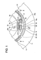
- FIG. 1 is a plan view of an example of the dram brake with the mechanical brake actuator according to the first example
- FIG. 2 is a cross section view of FIG. 1 taken along the line II-II;
- FIG. 3 is a cross section view of FIG. 1 taken along the line III-III;
- FIG. 4 is an exploded perspective view of the mechanical brake actuator according to the first example
- FIG. 5 is an enlarged view of the mechanical brake actuator structure and operation according to the first example, which illustrates the condition where the free end of the brake lever is exposed from the opening of the space of the strut in the cable releasing direction;
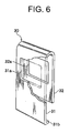
- FIG. 6 is a perspective view of a partially omitted clip according to the first example
- FIG. 7 is a cross section view of the mechanical brake actuator prior to the insertion of the connecting pin
- FIG. 8 is an enlarged view of the mechanical brake actuator structure and operation prior to the insertion of the connecting pin, which illustrates the condition where the free end of the brake lever is exposed from the opening of the space of the strut in the cable releasing direction side;
- FIG. 9 is a cross section view of the mechanical actuating mechanism according to the second example, which illustrates the operation thereof and shows the condition of restricting the movement of the connecting pin by the clip, which is slideable in a vertical direction of the strut;
- FIG. 10 is a cross section view of the mechanical actuating mechanism according to the third example, which illustrates the operation thereof and shows the condition of restricting the movement of the connecting pin by the clip, which is slidable in a lateral direction of the strut;
- FIG. 11 is an explanatory view of the operation of the mechanical actuating mechanism according to the fourth example, which shows an enlarged view illustrating the condition where the rotating clip disables the brake lever rotation in the cable releasing direction;
- FIG. 1 is a plan view of an example of the drum brake device with the mechanical brake actuator
- FIGS. 2 and 3 are cross-section views of FIG. 1
- FIG. 4 is an exploded perspective view of the mechanical actuating mechanism.
- a pair of brake shoes 12, 13 are movably mounted, via a shoe hold mechanism (not shown in the figures), on a back plate 11 which is fixed on a stationary portion 10 of a vehicle, and a pair of facing one ends of the brake shoes 12, 13 are supported by raised portions 16a, 16a of a later described anchor 16 while the other ends also facing each other, not shown in the figures, are linked via a linking part.
- a pair of shoe return springs (where only one shoe return spring 19 of the two shoe return springs appears in the figures), extended between both brake shoes 12, 13, maintains a condition of abutment between both ends of both brake shoes 12, 13 and linking part and between both ends and the anchor 16.
- a mechanical actuating mechanism 22 which expands one ends of both brake shoes 12, 13 is comprised of a strut 23, a brake lever 24, a pivot pin 25, and a washer 26, which is positioned adjacent to the raised portion 16a of the anchor 16 between both brake shoes 12, 13.
- the superposing portion at one side of the facing plates 23b, 23c has a shoe engagement groove 23f while the other side has pivotal holes 23g, 23g formed therein.
- the bridge portion 23a bridging over and connecting the upper portions of the facing plates 23b, 23c, shuts one section of the wide space 23d, and at the same time restricts a clockwise rotation of the brake lever 24, as shown in FIG. 2.
- the clip 30 is set on one facing plate 23b to restrict the movement of the connecting pin 43.
- the notched groove 23i permitting the connecting pin 43 to pass therethrough, is provided around an upper end of one facing plate 23b where the clip 30 is set thereon; a positioning recess 23k, which fixes a temporal setting position of the clip 30, is provided around an intermediate portion of the external side surface thereof; and a disengagement preventing groove 23m, to prevent the clip 30 from moving laterally, is provided around a lower portion of the external side surface.
- the positioning recess 23k and the disengagement preventing groove 23m function to position and secure the clip 30.
- the other facing plate 23c while an upper end surface of the brake lever 24 abutting against the bridge portion 23a of the strut 23, when the connecting pin 43 is inserted in the later described connecting holes 42c, 24f of the brake cable 40 and the brake lever 24, abuts against an end of the connecting pin 43.
- the bridge portion 23a, the brake lever 24, and both facing plates 23b, 23c, while the brake lever 24 abutting against the bridge portion 23a, interact each other so that one facing plate 23b permits the connecting pin 43 to pass therethrough while the other facing plate 23c prevents the connecting pin 43 from passing therethrough.
- the brake lever 24, one of the components of the mechanical actuating mechanism 22, is made of one plate, which is positioned and retained in the spaces 23d, 23e of the strut 23.
- a shoe engagement groove 24b is formed at a proximal portion 24a of the brake lever 24, wherein a pivot hole 24d, though which a pivot pin 25 is penetrated, is formed in a projection 24c at one end thereof having a shoe engagement groove 24b, a washer 26 is clipped on an end of the pivot pin 25 as penetrating through pivot holes 23g, 24d, 23g of the strut 23 and the brake lever 24, thereby pivotally supporting the brake lever 24 relative to the strut 23.
- the clockwise rotation of the brake lever 24 in FIG. 2 is restricted as an upper end surface thereof abutting against the bridge portion 23a of the strut 23.
- a brake cable connecting hole 24f is formed at a free end 24e of the brake lever 24. And then a cable end 42 fixed to the end of the inner cable 41, which constitute a later described brake cable 40, can be connected via a connecting pin 43.
- the strut 23 and the brake lever 24, which constitute the mechanical actuating mechanism 22 have projections 23h, 24h at a cable operational direction side, which are slidably landed on the heads of installation bolts 20, 21 as shown in FIG. 2.
- the brake cable 40 is comprised of an inner cable 41 and an outer casing 44.
- the clevis-shaped cable end 42 is fixed on the end of the inner cable 41, and a pair of forked legs 42b, 42b are extending from a proximal end 42a of the cable end 42.
- the legs 42b, 42b have connecting holes 42c, 42c, which are directly facing each other for the connecting pin 43 to penetrate therethrough.
- the clip 30, used to prevent the connecting pin 43 from disengaging, is slidably clipped on one facing plate 23b of the strut 23.
- the clip 30 of this example is formed by bending one thin spring steel plate into a U or C shape, resulting in one pair of facing clipping pieces 31, 32 to be resiliently clipped on one facing plate 23b of the strut 23.
- One clipping piece 31 of the pair of facing clipping pieces 31, 32 which abuts against the external side surface of one facing plate 23b, around its intermediate portion, has a by-pass hole 31a of a sufficient size permitting the connecting pin 43 to pass through, and around its end, is bent toward the other facing plate 23c to form a hook 31b, which can be hooked in a positioning recess 23k and on the displacement preventing groove 23m.
- the width of the hook 31b is slightly shorter than the width of the displacement preventing groove 23m to prevent the hook 31b from moving laterally within the displacement preventing groove 23m.
- the other clipping piece 32 which abuts against an internal side surface of one facing plate 23b, around its intermediate portion, has a by-pass hole 32a with sufficient size to permit the connecting pin 43 to pass through.
- Both by-pass holes 31a, 32a are arranged to face each other, and when the hook 31b of one clipping piece 31 being hooked in the positioning recess 23k of the strut 23, the connecting pin 43 can pass therethrough while when the clip 30 is pushed to slide to temporarily set the hook 31b in the displacement preventing groove 23m of the strut 23, the connecting pin 43 abuts against the clip 30 to restrict the displacement of the connecting pin 43.
- both by-pass holes 31a and 32a are square holes; however the holes can be round or other shapes.
- the cable end 42 does not physically disconnect from the brake lever 24 during the transportation of the drum brake device.
- the clip 30 engages with the positioning recess 23k of the strut 23 and the displacement preventing groove 23m individually so as to position the clip 30 at a different position relative to one facing plate 23b.
- the upper end surface of the brake lever 24 in this example abuts against the bridge portion 23a of the strut 23, and the clip 30 clipped on one facing plate 23b of the strut 23 slides vertically to change the positions of both by-pass holes 31a, 32a relative to one facing plate 23b, while restricting the brake lever 24 to rotate in the cable releasing direction, thereby permitting the connecting pin 43 to pass therethrough and restricting the movement of the connecting pin 43 thereafter.
- FIGS. 7 and 8 show a condition of the mechanical actuator mechanism 22 prior to connecting the brake cable 40 to the brake lever 24.
- Positioning of the clip 30 is accomplished not only by the engagement point of the hook 31b and the positioning recess 23k, but also by elastically clipping one facing plate 23b on the pair of clipping pieces 31, 32, thereby providing stable positioning and eliminating the possibility of dropping during the transportation of the drum brake.
- the inner cable 41 is pinched by fingers to be inserted in to a guide pipe 45, and the cable end 42, fixed at the end of the inner cable 41, passes through the wide space 23d of the strut 23 to reach the free end 24e of the brake lever 24, and the free end 24e is retained between a pair of legs 42b and 42b.
- the connecting hole 42c is designed such that one portion of the connecting hole 24f at the other facing plate 23c of the strut 23 is shut and that the connecting hole 42c at one facing plate 23b is entirely exposed from the notched groove 23i.
- the hook 31b engages with the displacement preventing groove 23m formed on one facing plate 23b.
- the hook 31b is positioned as abutting against the side surface of the displacement preventing groove 23m, which effectively prevents the clip 30 not only from displacing laterally but also moving in the opposite direction of pushing the clip 30 as hooking on a bottom surface of the displacement preventing groove 23m.
- a casing cap 44a of the outer casing 44 is fixed at the other end of a guide pipe 45 with a ring 46, and an operation of connecting the cable end 42 to the brake lever 24 is completed.
- FIG. 2 Accordingly thereafter, if the brake lever 24 begins to rotate in the cable releasing direction, the brake lever 24 abuts against the bridge portion 23a of the strut 23, thereby restricting the further rotation thereof. (See FIG. 5). At this time, the free movement of the connecting pin 43 is restricted by the other facing plate 23c of the strut 23 and the other clipping piece 32 of the clip 30, thereby constantly positioning the connecting pin 43 in the wide space 23c of the strut 23, and the cable end 42 can not physically disconnect from the brake lever 24.
- the cable end 42 needs to be disconnect from the brake lever 24, such as for exchanging the brake cable 40
- the clip 30 is pulled up as clipping on one facing plate 23b to be released from the notched groove 23i formed on one facing plate 23b of the strut 23, the connecting pin 43 can easily removed therefrom.
- This example remarkably improves setting operability of the clip 30 by simple operation of setting the clip 30 on one facing plate 23b of the strut 23.
- the width of the clip 30 can be narrow because it is only required to set on one facing plate 23b of the pair of facing plates 23b and 23c therefore, compared with the conventional clip that needs to be set on the entire strut, the present invention is more economical in that the smaller clip 30 reduces the spring steel usage and the clip 30 can be formed by a simple bending process.
- the notched groove 23i formed on the strut 23 exists only on one facing plate 23b, and there is no need to have another notched groove on the other facing plate 23c, thereby limiting the degradation of the stiffness of the strut 23.
- the clip 30 does not set on the bridge portion 23a of the strut 23, which maintains the stiffness of the bridge portion 23a. Furthermore, in this example, the free movement of the connecting pin 43 can be restricted by a combination of the notched groove 23i, formed on one facing plate 23b of the strut 23, and the clip 30, thereby not receiving any influence of the height of the bridge portion 23a to be formed on the strut 23. Accordingly, the height of the bridge portion can be lower, which can satisfy the strong demand of lowering the height of the brake device.
- the clip 130 to be used in the second example has a simple structure wherein it is formed by bending one thin spring steel plate in a U-shape so as to resiliently clip one facing plate 123b of the strut 123, and without forming the by-pass hole on the pair of facing clipping pieces 131, 132 as shown in the first example, an intermediate portion of one clipping piece 131 is bent to form the hook 131b, simply hooking the same on a positioning groove 123k formed on one facing plate 123b.
- the clip 130 is pushed to catch both side surfaces of one facing plate 123b of the strut 123 and to hold one facing plate 123b of the strut 123 by the resilient force of the clip 130, and the hook 131b formed on one clipping piece 131 of the clip 130 fits in the positioning groove 123k formed on an external side surface of one facing plate 123b, thereby simplifying and securing the positioning process for the clip 130 and preventing the disengagement of the clip 130 from the strut 123 even if the mechanical brake actuator is exposed to vibration or impact during car driving.
- the mechanical brake actuator with regard to the third example will be explained with reference to FIG. 10.
- the clip 230 to be used in this example is formed by bending one thin spring steel plate in to a C-shape so as to be able to make a lateral slide while resiliently holding one facing plate 223b of the strut 223.
- the clip 230 of this example has no hole in one pair of clipping pieces 231 and 232 (the reference number 232 is omitted in the drawings) as same as the second example.
- One clipping piece 231 of the clip 230 has the external side surface of one facing plate 223b of the strut 223 and a fittable known convexo-concave section 233.
- the convexo-concave section 233 can be provided at one location, providing the convexo-concave section 233 at several locations gives more stable positioning of the clip 230.
- the clip 230 is set on the strut 223 away from the notched groove 223i, which is formed on one clipping piece 223b of the strut 223, in a longitudinal direction of the brake lever 24 so as to release the notched groove 223i.
- the clip 230 is slid in a lateral direction of the strut 223 so as to shut the notched groove 223i.
- the free movement of the connecting pin 43 is restricted, as described in the first example, by the other facing plate of the strut 223 and the other clipping piece 232 of the clip 230, and the cable end 42 does not physically disconnect from the brake lever 24.
- This example provides an advantage of simplifying the disengagement preventing operation of the connecting pin 43 by making a simple movement of the clip 230 along a side end of one facing plate 223b of the strut 223.
- the mechanical brake actuator with regard to the fourth example will be explained with reference to FIG. 11.
- the clip 330 used in this example is formed by bending one thin spring steel plate in a C-shape so as to be rotatable while resiliently holding one facing plate 323b of the strut 323.
- the clip 330 of this example has no hole in one pair of clipping pieces 331 and 332 (the reference number 332 is omitted in the drawings) as same as the second and third examples.
- One clipping piece 331 of the clip 330 has an inner and external side surfaced of one facing plate 323b of the strut 323 and a fittable known convexo-concave section 333, wherein the convexo-concave section 333 is a rotational center of the clip 330.
- the clip 330 leans toward the left so as to release the notched groove 323i, which is formed on one clipping piece 331 of the strut 323.
- the free movement of the connecting pin 43 is restricted, as described in the first-third examples, by the other facing plate 323c of the strut 323 and the other clipping piece 332 of the clip 330, and the cable end 42 does not physically disconnect from the brake lever 24.
- the clip 330 is simply rotated, thereby providing an advantage of further simplification in disengagement prevention of the connecting pin 43.
Landscapes
- Engineering & Computer Science (AREA)
- General Engineering & Computer Science (AREA)
- Multimedia (AREA)
- Mechanical Engineering (AREA)
- Braking Arrangements (AREA)
Abstract
Description
- The present invention relates to a mechanical brake actuator providing an avoidance means to prevent a brake cable from disconnecting from a brake lever.
- This type of brake actuator has a mechanical actuating mechanism, which is comprised of a plate-like brake lever, a strut pivotally retained in the brake lever, and a pivotal pin, wherein the mechanical actuating mechanism is positioned between a pair of brake shoes, and the brake lever and the strut relatively rotates as operating, i.e., pulling and releasing a brake cable connected to the brake lever, also spreading the brake lever and the strut apart from each other.
- Then, after a connecting pin that is penetrating through a cable connecting hole of the brake cable and a connecting hole of the brake lever, which is exposed from an opening of the strut as aligning both holes in series, thereby connecting the brake cable and the brake lever, an almost C-shape clip fits over an exterior of the strut, and recesses, which are formed on both internal side surfaces of the clip, engage with protrusions, which are formed on both external surfaces of the strut, for the clip to position the brake lever in a space between the facing plates of the strut. (See the paragraphs 0015-0016 and FIGS. 2-4 of the reference patent 1)
- Furthermore, instead of the above-described structure, there exists an integral type where the clip is rotatably set on the strut. (See the paragraphs 0020-0023 and FIGS. 5-8 of the reference patent 1)
- Also, for another means to position the brake lever in the space of the strut, a spring steel plate is bent to form a resilient member, which is to be set on the strut or the brake lever, where a resilient piece, formed on a part of the resilient member, is positioned along a rotational track of the brake lever, so as to restrict the rotation of the brake lever. (See the paragraphs 0018-0039 and FIGS. 2-12 of the reference patent 2)
- The reference Patent 1 is the
Japanese Provisional Patent Publication No. 2001-349360 Japanese Provisional Patent Publication No. 2004-108458 - The invention disclosed in the reference patent 1 has the following problems.
- (1) The clip needs to be wide so as to fit over the exterior of the strut; therefore, the material cost of the clip increases. Forming processes for fitting means on both clip and strut is necessary to prevent the clip from disengaging from the strut; therefore, the manufacturing cost is increased.
- (2) If the clip is integrated with the strut, to provide rotational axis on both external surfaces of the facing plates is necessary, which increases the manufacturing cost.
- (3) Both sides of the facing plates of the strut have notched grooves, which degrade the stiffness of the strut. Also, for a brake device which needs to lower the height, as the bridge portion of the strut is lowered, the notched groove becomes deeper, which degrades the stiffness of the strut.
- The invention disclosed in the reference patent 2 has the following problems.
- (1) If the resilient member is inserted and set in a wide space of the strut, the space between the facing plates of the strut becomes larger. Therefore, this configuration gives a nonpreferable layout, and it is difficult to apply in a small size brake device. If a brake device with a flexible layout choice is usable, which degrades the stiffness of the strut, the strut deforms easily.
- (2) If the resilient member is set on the bridge portion of the strut, the bridge portion needs to be smaller. Therefore, the facing plates, a constant space therebeween being maintained by the bridge portion, are more susceptible to an external force, thereby increasing the possibility of bending to open the same.
- (3) If the resilient member is set on the brake lever, which degrades the stiffness of the bridge portion.
- The present invention was made in consideration of the above problems, and an object of the invention is to provide a mechanical brake actuator realizing the miniaturization of the entire device and the reduction of the parts costs. Furthermore, another object of the invention is to provide a mechanical brake actuator remarkably improving the clip setting operation.
- In order to accomplish the above-described objects, the mechanical brake actuator of the present invention comprises (a) a strut to engage with one brake shoe, the strut including two facing plates and a bridge portion connecting the facing plates; and (b) a plate-like brake lever to engage with the other brake shoe and to be retained in a space between the facing plates of the strut, the brake lever including a proximal end pivotally supported at the strut. The brake lever and the strut relatively rotate to spread apart from each other as pulling a brake cable connected to a free end of the brake lever via a connecting pin, wherein the facing plates are designed such that one of the facing plates permits a movement of the connecting pin to connect the brake cable and the free end of the brake lever, while the brake lever is rotating in a cable releasing direction, and that the other of the facing plates restricts a movement of the connecting pin, and a clip is set on one of the facing plates so as to restrict the movement of the connecting pin upon connecting the brake cable and the brake lever via the connecting pin. The invention prevents the brake cable from disengaging by the simple operation of fitting the small clip on one facing plate of the strut.
- Furthermore, the invention is such that in the above-described mechanical brake actuator, the notched groove is formed on one of the facing plates to permit the movement of the connecting pin therethrough. Still further, the invention is such that in the above-described mechanical brake actuator, the means to restrict a lateral movement of the clip is provided on one of the facing plates. Still further, the invention is such that in the above-described mechanical brake actuator, the clip is temporarily set on one of the facing plates. Still further, the invention is such that in the above-described mechanical brake actuator, the clip is slidably set on one of the facing plates. Yet further, the invention is such that in the above-described mechanical brake actuator, the clip is rotatably set on one of the facing plates.
- The present invention has the following advantages.
- (1) Simply setting the clip on one of two facing plates of the strut improves the setting operation of the clip.
- (2) To provide notched grooves at both facing plates of the strut is not necessary, thereby limiting the degradation of the entire stiffness of the strut. Furthermore, the invention prevents the degradation of the stiffness of the bridge portion compared with the situation where the clip is set on the bridge portion of the strut.
- (3) The clip is set on one of the two facing plates of the strut, which downsizes the clip and can be manufactured by a simple bending process, thereby decreasing the material cost and the manufacturing cost of the clip.
- (4) A combination of the strut and the clip, which is set on one of the facing plates, can restrict the free movement of the connecting pin, which has no effect of the height of the bridge portion to be formed on the strut. Accordingly, the height of the bridge portion can be lower, which can satisfy the strong demand of lowering the height of the brake device.
- The above and other objects of the present invention will become readily apparent by reference to the following detailed description when considered in conjunction with the accompanying drawings wherein:
- FIG. 1 is a plan view of an example of the dram brake with the mechanical brake actuator according to the first example;
- FIG. 2 is a cross section view of FIG. 1 taken along the line II-II;
- FIG. 3 is a cross section view of FIG. 1 taken along the line III-III;
- FIG. 4 is an exploded perspective view of the mechanical brake actuator according to the first example;
- FIG. 5 is an enlarged view of the mechanical brake actuator structure and operation according to the first example, which illustrates the condition where the free end of the brake lever is exposed from the opening of the space of the strut in the cable releasing direction;
- FIG. 6 is a perspective view of a partially omitted clip according to the first example;
- FIG. 7 is a cross section view of the mechanical brake actuator prior to the insertion of the connecting pin;
- FIG. 8 is an enlarged view of the mechanical brake actuator structure and operation prior to the insertion of the connecting pin, which illustrates the condition where the free end of the brake lever is exposed from the opening of the space of the strut in the cable releasing direction side;
- FIG. 9 is a cross section view of the mechanical actuating mechanism according to the second example, which illustrates the operation thereof and shows the condition of restricting the movement of the connecting pin by the clip, which is slideable in a vertical direction of the strut;
- FIG. 10 is a cross section view of the mechanical actuating mechanism according to the third example, which illustrates the operation thereof and shows the condition of restricting the movement of the connecting pin by the clip, which is slidable in a lateral direction of the strut;
- FIG. 11 is an explanatory view of the operation of the mechanical actuating mechanism according to the fourth example, which shows an enlarged view illustrating the condition where the rotating clip disables the brake lever rotation in the cable releasing direction;
- In the following sections, a mechanical brake actuator relating to the invention will be explained.
- FIG. 1 is a plan view of an example of the drum brake device with the mechanical brake actuator, FIGS. 2 and 3 are cross-section views of FIG. 1, and FIG. 4 is an exploded perspective view of the mechanical actuating mechanism. The first example of the invention will be explained with reference to the drawings.
- A pair of
brake shoes back plate 11 which is fixed on astationary portion 10 of a vehicle, and a pair of facing one ends of thebrake shoes portions anchor 16 while the other ends also facing each other, not shown in the figures, are linked via a linking part. A pair of shoe return springs (where only one shoe returnspring 19 of the two shoe return springs appears in the figures), extended between bothbrake shoes brake shoes anchor 16. - A
mechanical actuating mechanism 22 which expands one ends of bothbrake shoes strut 23, abrake lever 24, apivot pin 25, and awasher 26, which is positioned adjacent to the raisedportion 16a of theanchor 16 between bothbrake shoes - The
strut 23, which is a component of themechanical actuating mechanism 22 and is made of one plate, has abridge portion 23a at an intermediate portion between both longitudinal ends of thestrut 23 and facingplates plates space 23d, is continuously formed at the other ends thereof. The superposing portion at one side of the facingplates shoe engagement groove 23f while the other side has pivotal holes 23g, 23g formed therein. Thebridge portion 23a, bridging over and connecting the upper portions of the facingplates wide space 23d, and at the same time restricts a clockwise rotation of thebrake lever 24, as shown in FIG. 2. - Also, the
clip 30 is set on one facingplate 23b to restrict the movement of the connectingpin 43. - The notched
groove 23i, permitting the connectingpin 43 to pass therethrough, is provided around an upper end of one facingplate 23b where theclip 30 is set thereon; apositioning recess 23k, which fixes a temporal setting position of theclip 30, is provided around an intermediate portion of the external side surface thereof; and adisengagement preventing groove 23m, to prevent theclip 30 from moving laterally, is provided around a lower portion of the external side surface. Thepositioning recess 23k and thedisengagement preventing groove 23m function to position and secure theclip 30. - The other facing
plate 23c, while an upper end surface of thebrake lever 24 abutting against thebridge portion 23a of thestrut 23, when the connectingpin 43 is inserted in the later described connectingholes brake cable 40 and thebrake lever 24, abuts against an end of the connectingpin 43. Thebridge portion 23a, thebrake lever 24, and both facingplates brake lever 24 abutting against thebridge portion 23a, interact each other so that one facingplate 23b permits the connectingpin 43 to pass therethrough while the other facingplate 23c prevents the connectingpin 43 from passing therethrough. - The
brake lever 24, one of the components of themechanical actuating mechanism 22, is made of one plate, which is positioned and retained in thespaces strut 23. Ashoe engagement groove 24b is formed at aproximal portion 24a of thebrake lever 24, wherein apivot hole 24d, though which apivot pin 25 is penetrated, is formed in aprojection 24c at one end thereof having ashoe engagement groove 24b, awasher 26 is clipped on an end of thepivot pin 25 as penetrating throughpivot holes 23g, 24d, 23g of thestrut 23 and thebrake lever 24, thereby pivotally supporting thebrake lever 24 relative to thestrut 23. The clockwise rotation of thebrake lever 24 in FIG. 2 is restricted as an upper end surface thereof abutting against thebridge portion 23a of thestrut 23. - A brake
cable connecting hole 24f is formed at afree end 24e of thebrake lever 24. And then acable end 42 fixed to the end of theinner cable 41, which constitute a later describedbrake cable 40, can be connected via a connectingpin 43. - Also, the
strut 23 and thebrake lever 24, which constitute themechanical actuating mechanism 22, haveprojections installation bolts - The
brake cable 40 is comprised of aninner cable 41 and anouter casing 44. The clevis-shapedcable end 42 is fixed on the end of theinner cable 41, and a pair of forkedlegs proximal end 42a of thecable end 42. Thelegs holes pin 43 to penetrate therethrough. - The
clip 30, used to prevent the connectingpin 43 from disengaging, is slidably clipped on one facingplate 23b of thestrut 23. - As shown in FIG. 6, the
clip 30 of this example is formed by bending one thin spring steel plate into a U or C shape, resulting in one pair of facing clippingpieces plate 23b of thestrut 23. Oneclipping piece 31 of the pair of facing clippingpieces plate 23b, around its intermediate portion, has a by-pass hole 31a of a sufficient size permitting the connectingpin 43 to pass through, and around its end, is bent toward the other facingplate 23c to form ahook 31b, which can be hooked in apositioning recess 23k and on thedisplacement preventing groove 23m. The width of thehook 31b is slightly shorter than the width of thedisplacement preventing groove 23m to prevent thehook 31b from moving laterally within thedisplacement preventing groove 23m. - The
other clipping piece 32, which abuts against an internal side surface of one facingplate 23b, around its intermediate portion, has a by-pass hole 32a with sufficient size to permit the connectingpin 43 to pass through. Both by-pass holes hook 31b of oneclipping piece 31 being hooked in thepositioning recess 23k of thestrut 23, the connectingpin 43 can pass therethrough while when theclip 30 is pushed to slide to temporarily set thehook 31b in thedisplacement preventing groove 23m of thestrut 23, the connectingpin 43 abuts against theclip 30 to restrict the displacement of the connectingpin 43. In this example, both by-pass holes - Because of this structure, the
cable end 42 does not physically disconnect from thebrake lever 24 during the transportation of the drum brake device. - The
clip 30 engages with thepositioning recess 23k of thestrut 23 and thedisplacement preventing groove 23m individually so as to position theclip 30 at a different position relative to one facingplate 23b. - That is, the upper end surface of the
brake lever 24 in this example abuts against thebridge portion 23a of thestrut 23, and theclip 30 clipped on one facingplate 23b of thestrut 23 slides vertically to change the positions of both by-pass holes plate 23b, while restricting thebrake lever 24 to rotate in the cable releasing direction, thereby permitting the connectingpin 43 to pass therethrough and restricting the movement of the connectingpin 43 thereafter. In other words, when thebrake lever 24 abuts against thebridge portion 23a of thestrut 23, the by-pass holes clip 30 temporary setting on thestrut 23 are aligned in the same center line as the notchedgroove 23i formed on one facingplate 23b of thestrut 23 and the connectingholes free end 24e of thebrake lever 24, thereby establishing interrelation for inserting and setting the connectingpin 43. - A connecting process for the brake cable will be explained next. FIGS. 7 and 8 show a condition of the
mechanical actuator mechanism 22 prior to connecting thebrake cable 40 to thebrake lever 24. - In order to temporarily set the
clip 30 on thestrut 23, an opening of theclip 30 pushed against the notchedgroove 23i formed on one facingplate 23b of thestrut 23 so as to open the pair of facing clippingpieces hook 31b at the end of oneclipping piece 31 is pushed until it reaches to thepositioning recess 23k of thestrut 23. By the simple process described above, the resilient force of oneclipping piece 31 positions thehook 31b into thepositioning recess 23k. When thehook 31b of theclip 30 is temporarily set on thestrut 23, both by-pass holes clip 30 are superposed and almost aligned with the notchedgroove 23i formed on one facingplate 23b of thestrut 23 for the connectingpin 43 to pass therethrough. Positioning of theclip 30 is accomplished not only by the engagement point of thehook 31b and thepositioning recess 23k, but also by elastically clipping one facingplate 23b on the pair of clippingpieces - The
inner cable 41 is pinched by fingers to be inserted in to aguide pipe 45, and thecable end 42, fixed at the end of theinner cable 41, passes through thewide space 23d of thestrut 23 to reach thefree end 24e of thebrake lever 24, and thefree end 24e is retained between a pair oflegs inner cable 41 is pushed until thebrake lever 24 abuts against thebridge portion 23a of thestrut 23, thefree end 24e projects from thewide space 23d of thestrut 23 in the cable releasing direction. The connectinghole 42c is designed such that one portion of the connectinghole 24f at the other facingplate 23c of thestrut 23 is shut and that the connectinghole 42c at one facingplate 23b is entirely exposed from the notchedgroove 23i. (See FIGS. 7 and 8) As confirming both by-pass holes clip 30 temporarily setting on thestrut 23, the notchedgroove 23i, and the connectingholes pin 43 is inserted from outside at one facingplate 23b of theclip 30. The connectingpin 43 is pushed until the end thereof abuts against the facingplate 23c, and the connection between thebrake lever 24 and thecable end 42 are completed. - When the
cable end 42 is connected to thebrake lever 24, as shown in FIG. 8, as an upper end of theclip 30 is pushed in the cable operating direction, the engagement between thehook 31b of theclip 30 and thepositioning recess 23k of thestrut 23 is released. - When the
clip 30 is further pushed, thehook 31b engages with thedisplacement preventing groove 23m formed on one facingplate 23b. Thehook 31b is positioned as abutting against the side surface of thedisplacement preventing groove 23m, which effectively prevents theclip 30 not only from displacing laterally but also moving in the opposite direction of pushing theclip 30 as hooking on a bottom surface of thedisplacement preventing groove 23m. - By pushing the
clip 30 and then sliding theclip 30 in the longitudinal direction, positions of both by-pass holes pieces groove 23i is shut by the pair of clippingpieces pin 43 is restricted between the other facingplate 23c and theother clipping piece 32 of theclip 30. - Finally, a
casing cap 44a of theouter casing 44 is fixed at the other end of aguide pipe 45 with aring 46, and an operation of connecting thecable end 42 to thebrake lever 24 is completed. (See FIG. 2) Accordingly thereafter, if thebrake lever 24 begins to rotate in the cable releasing direction, thebrake lever 24 abuts against thebridge portion 23a of thestrut 23, thereby restricting the further rotation thereof. (See FIG. 5). At this time, the free movement of the connectingpin 43 is restricted by the other facingplate 23c of thestrut 23 and theother clipping piece 32 of theclip 30, thereby constantly positioning the connectingpin 43 in thewide space 23c of thestrut 23, and thecable end 42 can not physically disconnect from thebrake lever 24. - Also, when the
cable end 42 needs to be disconnect from thebrake lever 24, such as for exchanging thebrake cable 40, after releasing the engagement between thehook 31b of theclip 30 and thedisengagement preventing groove 23m formed on one facingplate 23b of thestrut 23 by pinching theclipping piece 31, theclip 30 is pulled up as clipping on one facingplate 23b to be released from the notchedgroove 23i formed on one facingplate 23b of thestrut 23, the connectingpin 43 can easily removed therefrom. - This example remarkably improves setting operability of the
clip 30 by simple operation of setting theclip 30 on one facingplate 23b of thestrut 23. Furthermore, the width of theclip 30 can be narrow because it is only required to set on one facingplate 23b of the pair of facingplates smaller clip 30 reduces the spring steel usage and theclip 30 can be formed by a simple bending process. The notchedgroove 23i formed on thestrut 23 exists only on one facingplate 23b, and there is no need to have another notched groove on the other facingplate 23c, thereby limiting the degradation of the stiffness of thestrut 23. Also, theclip 30 does not set on thebridge portion 23a of thestrut 23, which maintains the stiffness of thebridge portion 23a. Furthermore, in this example, the free movement of the connectingpin 43 can be restricted by a combination of the notchedgroove 23i, formed on one facingplate 23b of thestrut 23, and theclip 30, thereby not receiving any influence of the height of thebridge portion 23a to be formed on thestrut 23. Accordingly, the height of the bridge portion can be lower, which can satisfy the strong demand of lowering the height of the brake device. - In the following section, the mechanical brake actuator relating to the second example will be explained with reference to FIG. 9. The
clip 130 to be used in the second example has a simple structure wherein it is formed by bending one thin spring steel plate in a U-shape so as to resiliently clip one facingplate 123b of thestrut 123, and without forming the by-pass hole on the pair of facing clippingpieces clipping piece 131 is bent to form thehook 131b, simply hooking the same on apositioning groove 123k formed on one facingplate 123b. - In this example, by inserting the connecting
pin 43 in the connectingholes groove 123i formed on one facingplate 123b while thebrake lever 24 is abutting against the bridge portion (not shown in FIG. 9) of thestrut 123, after completing the connection between thebrake lever 24 and thecable end 42, theclip 130 with no hole later set on one facingplate 123b to shut the notchedgroove 123i. After setting theclip 130 without a hole, the free movement of the connectingpin 43 is restricted, as described in the first example, by the other facingplate 123c of thestrut 123 and theother clipping piece 132 of theclip 130, and thecable end 42 does not physically disconnect from thebrake lever 24. - In this example, in addition to the same advantages as described in the first example, there is a further advantage of eliminating a forming process for the by-pass hole when manufacturing the
clip 130, which simplifies the manufacturing process for thestrut 123. Furthermore, in this example, as described in the first example, theclip 130 is pushed to catch both side surfaces of one facingplate 123b of thestrut 123 and to hold one facingplate 123b of thestrut 123 by the resilient force of theclip 130, and thehook 131b formed on oneclipping piece 131 of theclip 130 fits in thepositioning groove 123k formed on an external side surface of one facingplate 123b, thereby simplifying and securing the positioning process for theclip 130 and preventing the disengagement of theclip 130 from thestrut 123 even if the mechanical brake actuator is exposed to vibration or impact during car driving. - The mechanical brake actuator with regard to the third example will be explained with reference to FIG. 10. The
clip 230 to be used in this example is formed by bending one thin spring steel plate in to a C-shape so as to be able to make a lateral slide while resiliently holding one facingplate 223b of thestrut 223. Theclip 230 of this example has no hole in one pair of clippingpieces 231 and 232 (the reference number 232 is omitted in the drawings) as same as the second example. Oneclipping piece 231 of theclip 230 has the external side surface of one facingplate 223b of thestrut 223 and a fittable known convexo-concave section 233. Although the convexo-concave section 233 can be provided at one location, providing the convexo-concave section 233 at several locations gives more stable positioning of theclip 230. - In this example, prior to connecting the
cable end 42 to thebrake lever 24, as shown in the chain double-dashed line in FIG. 10, theclip 230 is set on thestrut 223 away from the notchedgroove 223i, which is formed on oneclipping piece 223b of thestrut 223, in a longitudinal direction of thebrake lever 24 so as to release the notchedgroove 223i. By inserting the connectingpin 43 in the connectingholes groove 223i formed on one facingplate 223b while thebrake lever 24 is abutting against thebridge portion 223a of thestrut 223, after completing the connection between thebrake lever 24 and thecable end 42, theclip 230 is slid in a lateral direction of thestrut 223 so as to shut the notchedgroove 223i. After sliding theclip 230, the free movement of the connectingpin 43 is restricted, as described in the first example, by the other facing plate of thestrut 223 and the other clipping piece 232 of theclip 230, and thecable end 42 does not physically disconnect from thebrake lever 24. - This example provides an advantage of simplifying the disengagement preventing operation of the connecting
pin 43 by making a simple movement of theclip 230 along a side end of one facingplate 223b of thestrut 223. - The mechanical brake actuator with regard to the fourth example will be explained with reference to FIG. 11. The
clip 330 used in this example is formed by bending one thin spring steel plate in a C-shape so as to be rotatable while resiliently holding one facingplate 323b of thestrut 323. - The
clip 330 of this example has no hole in one pair of clippingpieces 331 and 332 (the reference number 332 is omitted in the drawings) as same as the second and third examples. Oneclipping piece 331 of theclip 330 has an inner and external side surfaced of one facingplate 323b of thestrut 323 and a fittable known convexo-concave section 333, wherein the convexo-concave section 333 is a rotational center of theclip 330. - In this example, prior to connecting the
cable end 42 to thebrake lever 24, as shown in the chain double-dashed line in FIG. 11, theclip 330 leans toward the left so as to release the notchedgroove 323i, which is formed on oneclipping piece 331 of thestrut 323. By inserting the connectingpin 43 in the connectingholes groove 323i formed on one facingplate 323b while thebrake lever 24 is abutting against thebridge portion 323a of thestrut 323, after completing the connection between thebrake lever 24 and thecable end 42, if theclip 330 rotates clockwise with the convexo-concave section 333 as the fulcrum, the pair of clippingpieces 331 and 332 of theclip 330 shuts the notchedgroove 323i. - After rotating the
clip 330, the free movement of the connectingpin 43 is restricted, as described in the first-third examples, by the other facing plate 323c of thestrut 323 and the other clipping piece 332 of theclip 330, and thecable end 42 does not physically disconnect from thebrake lever 24. - In this example, the
clip 330 is simply rotated, thereby providing an advantage of further simplification in disengagement prevention of the connectingpin 43. - It is readily apparent that the above-described embodiments have the advantage of wide commercial utility. It should be understood that the specific form of the invention hereinabove described is intended to be representative only, as certain modifications within the scope of these teachings will be apparent to those skilled in the art. Accordingly, reference should be made to the following claims in determining the full scope of the invention.
Claims (6)
- A mechanical brake actuator comprising:(a) a strut (23; 123; 223; 323) to engage with one brake shoe (12), said strut including two facing plates (23b, 23c; 123b, 123c; 223b, 223c; 323b, 323c) and a bridge portion (23a; 123a; 223a; 323a) connecting said facing plates; and(b) a plate-like brake lever (24) to engage with the other brake shoe (13) and to be retained in a space between said facing plates of said strut, said brake lever including a proximal end pivotally supported at said strut, said brake lever and strut relatively rotate to spread apart from each other as pulling a brake cable (40) connected to a free end (24e) of said brake lever via a connecting pin (43), characterized in that
said facing plates are designed such that one of said facing plates permits a movement of said connecting pin to connect said brake cable and the free end of said brake lever while the brake lever rotates in a cable releasing direction, and that the other of said facing plates restricts a movement of said connecting pin, and
a clip (30; 130; 230; 330) is set on one of said facing plates so as to restrict the movement of the connecting pin upon connecting the brake cable and the brake lever via the connecting pin. - The mechanical brake actuator according to claim 1, characterized in that
a notched groove (23i; 123i; 223i; 323i) is formed on one of said facing plates to permit said movement of said connecting pin therethrough. - The mechanical brake actuator according to claim 1, characterized in that
a means (23m) to restrict a lateral movement of said clip is provided on one of said facing plates. - The mechanical brake actuator according to claim 1, characterized in that
said clip is temporarily set on one of said facing plates. - The mechanical brake actuator according to claim 1, characterized in that
said clip is slidably set on one of said facing plates. - The mechanical brake actuator according to claim 1, characterized in that
said clip is rotatably set on one of said facing plates.
Applications Claiming Priority (1)
| Application Number | Priority Date | Filing Date | Title |
|---|---|---|---|
| JP2006004021A JP4721222B2 (en) | 2006-01-11 | 2006-01-11 | Mechanical brake actuator |
Publications (2)
| Publication Number | Publication Date |
|---|---|
| EP1808614A1 true EP1808614A1 (en) | 2007-07-18 |
| EP1808614B1 EP1808614B1 (en) | 2008-11-05 |
Family
ID=37872489
Family Applications (1)
| Application Number | Title | Priority Date | Filing Date |
|---|---|---|---|
| EP07290035A Expired - Fee Related EP1808614B1 (en) | 2006-01-11 | 2007-01-10 | Mechanical brake actuator |
Country Status (5)
| Country | Link |
|---|---|
| US (1) | US7815018B2 (en) |
| EP (1) | EP1808614B1 (en) |
| JP (1) | JP4721222B2 (en) |
| KR (1) | KR101330413B1 (en) |
| CN (1) | CN101000076B (en) |
Cited By (2)
| Publication number | Priority date | Publication date | Assignee | Title |
|---|---|---|---|---|
| EP2020525A1 (en) * | 2007-07-23 | 2009-02-04 | Nisshinbo Industries, Inc. | Mechanical type brake-operating device |
| EP2320105A3 (en) * | 2009-11-05 | 2012-01-25 | Akebono Corporation (North America) | A cable end retention clip assembly and method for a brake actuating lever |
Families Citing this family (6)
| Publication number | Priority date | Publication date | Assignee | Title |
|---|---|---|---|---|
| JP4723542B2 (en) * | 2007-08-10 | 2011-07-13 | 日清紡ホールディングス株式会社 | Drum brake actuator |
| US8267227B2 (en) * | 2008-07-22 | 2012-09-18 | Akebono Brake Corporation | Lever assembly featuring blind cable assembly |
| JP5342988B2 (en) | 2008-12-16 | 2013-11-13 | 日清紡ホールディングス株式会社 | Mechanical brake actuator for drum brake |
| DE102013215850B4 (en) | 2013-08-12 | 2016-06-02 | Saf-Holland Gmbh | Actuation device for a brake |
| CN105173499A (en) * | 2015-09-02 | 2015-12-23 | 广运机电(苏州)有限公司 | Cargo storing and fetching mechanism lifted through hydraulic driving |
| JP6651482B2 (en) * | 2017-06-23 | 2020-02-19 | 日信工業株式会社 | Drum brake device |
Citations (4)
| Publication number | Priority date | Publication date | Assignee | Title |
|---|---|---|---|---|
| EP1108917A2 (en) * | 1999-12-16 | 2001-06-20 | Nisshinbo Industries Inc. | Brake cable mounting structure for a drum brake |
| JP2001349360A (en) * | 2000-06-08 | 2001-12-21 | Akebono Brake Ind Co Ltd | Connection structure between lever and cable of mechanical drum brake |
| EP1174627A1 (en) * | 2000-07-17 | 2002-01-23 | Nisshinbo Industries, Inc. | Brake cable connecting apparatus for drum brake |
| EP1400721A1 (en) * | 2002-09-17 | 2004-03-24 | Nisshinbo Industries Inc. | Brake cable connecting apparatus for drum brake |
Family Cites Families (4)
| Publication number | Priority date | Publication date | Assignee | Title |
|---|---|---|---|---|
| DE9314350U1 (en) * | 1993-09-22 | 1995-01-26 | Lucas Ind Plc | Mechanical actuation device, in particular for motor vehicle brakes |
| JP4005894B2 (en) * | 2002-09-27 | 2007-11-14 | 日清紡績株式会社 | Brake cable connection device |
| JP2006105301A (en) * | 2004-10-06 | 2006-04-20 | Nisshinbo Ind Inc | Brake cable connecting device |
| JP4186012B2 (en) * | 2005-08-09 | 2008-11-26 | 日清紡績株式会社 | Mechanical brake actuator |
-
2006
- 2006-01-11 JP JP2006004021A patent/JP4721222B2/en not_active Expired - Fee Related
-
2007
- 2007-01-10 EP EP07290035A patent/EP1808614B1/en not_active Expired - Fee Related
- 2007-01-10 KR KR1020070002830A patent/KR101330413B1/en active IP Right Grant
- 2007-01-11 US US11/622,081 patent/US7815018B2/en active Active
- 2007-01-11 CN CN2007100012742A patent/CN101000076B/en not_active Expired - Fee Related
Patent Citations (5)
| Publication number | Priority date | Publication date | Assignee | Title |
|---|---|---|---|---|
| EP1108917A2 (en) * | 1999-12-16 | 2001-06-20 | Nisshinbo Industries Inc. | Brake cable mounting structure for a drum brake |
| JP2001349360A (en) * | 2000-06-08 | 2001-12-21 | Akebono Brake Ind Co Ltd | Connection structure between lever and cable of mechanical drum brake |
| EP1174627A1 (en) * | 2000-07-17 | 2002-01-23 | Nisshinbo Industries, Inc. | Brake cable connecting apparatus for drum brake |
| EP1400721A1 (en) * | 2002-09-17 | 2004-03-24 | Nisshinbo Industries Inc. | Brake cable connecting apparatus for drum brake |
| JP2004108458A (en) * | 2002-09-17 | 2004-04-08 | Nisshinbo Ind Inc | Connection device of brake cable |
Cited By (2)
| Publication number | Priority date | Publication date | Assignee | Title |
|---|---|---|---|---|
| EP2020525A1 (en) * | 2007-07-23 | 2009-02-04 | Nisshinbo Industries, Inc. | Mechanical type brake-operating device |
| EP2320105A3 (en) * | 2009-11-05 | 2012-01-25 | Akebono Corporation (North America) | A cable end retention clip assembly and method for a brake actuating lever |
Also Published As
| Publication number | Publication date |
|---|---|
| US7815018B2 (en) | 2010-10-19 |
| KR101330413B1 (en) | 2013-11-15 |
| KR20070075318A (en) | 2007-07-18 |
| EP1808614B1 (en) | 2008-11-05 |
| CN101000076A (en) | 2007-07-18 |
| US20070158149A1 (en) | 2007-07-12 |
| JP2007187195A (en) | 2007-07-26 |
| JP4721222B2 (en) | 2011-07-13 |
| CN101000076B (en) | 2010-09-01 |
Similar Documents
| Publication | Publication Date | Title |
|---|---|---|
| EP1808614B1 (en) | Mechanical brake actuator | |
| EP1752679B1 (en) | Mechanical brake actuator | |
| JP4468536B2 (en) | Operation cable connection device | |
| US6817450B2 (en) | Brake cable connecting apparatus for drum brake | |
| US6581729B1 (en) | Brake cable-fixing device for a parking brake | |
| EP2202424B1 (en) | Mechanical type brake actuator for drum brake | |
| JP3560846B2 (en) | Seat slide device | |
| EP1174627B1 (en) | Brake cable connecting apparatus for drum brake | |
| JP2006334063A (en) | Locking device of game machine | |
| EP1234995B1 (en) | Apparatus for connecting a brake cable to the actuating lever of a drum brake | |
| JP4242659B2 (en) | Brake cable connection device for drum brake | |
| EP1643153A2 (en) | Brake cable connecting apparatus for a drum brake device | |
| EP2020525A1 (en) | Mechanical type brake-operating device | |
| JP5270980B2 (en) | Vehicle seat slide device | |
| JP2000274460A (en) | Operation device for drum brake | |
| JP2520404Y2 (en) | Drum brake with parking brake mechanism | |
| JP2005331012A (en) | Structure of spring attachment | |
| JP2004116742A (en) | Connection device of brake cable | |
| US20090288922A1 (en) | Mechanical brake actuator | |
| JP2003321959A (en) | Locking device for game machine | |
| JP2000120735A (en) | Friction pad support structure for vehicle disc brake | |
| JP2002005209A (en) | Link member for mechanical drum brake and its assemblying method | |
| JP2004270882A (en) | Parking brake cable and parking brake cable connecting structure | |
| JP2008267554A (en) | Mechanical type brake applying device and method of its connection with brake cable |
Legal Events
| Date | Code | Title | Description |
|---|---|---|---|
| PUAI | Public reference made under article 153(3) epc to a published international application that has entered the european phase |
Free format text: ORIGINAL CODE: 0009012 |
|
| AK | Designated contracting states |
Kind code of ref document: A1 Designated state(s): AT BE BG CH CY CZ DE DK EE ES FI FR GB GR HU IE IS IT LI LT LU LV MC NL PL PT RO SE SI SK TR |
|
| AX | Request for extension of the european patent |
Extension state: AL BA HR MK YU |
|
| 17P | Request for examination filed |
Effective date: 20070804 |
|
| 17Q | First examination report despatched |
Effective date: 20070905 |
|
| AKX | Designation fees paid |
Designated state(s): FR GB |
|
| REG | Reference to a national code |
Ref country code: DE Ref legal event code: 8566 |
|
| GRAP | Despatch of communication of intention to grant a patent |
Free format text: ORIGINAL CODE: EPIDOSNIGR1 |
|
| GRAS | Grant fee paid |
Free format text: ORIGINAL CODE: EPIDOSNIGR3 |
|
| GRAA | (expected) grant |
Free format text: ORIGINAL CODE: 0009210 |
|
| AK | Designated contracting states |
Kind code of ref document: B1 Designated state(s): FR GB |
|
| REG | Reference to a national code |
Ref country code: GB Ref legal event code: FG4D |
|
| PLBE | No opposition filed within time limit |
Free format text: ORIGINAL CODE: 0009261 |
|
| STAA | Information on the status of an ep patent application or granted ep patent |
Free format text: STATUS: NO OPPOSITION FILED WITHIN TIME LIMIT |
|
| 26N | No opposition filed |
Effective date: 20090806 |
|
| GBPC | Gb: european patent ceased through non-payment of renewal fee |
Effective date: 20110110 |
|
| PG25 | Lapsed in a contracting state [announced via postgrant information from national office to epo] |
Ref country code: GB Free format text: LAPSE BECAUSE OF NON-PAYMENT OF DUE FEES Effective date: 20110110 |
|
| REG | Reference to a national code |
Ref country code: FR Ref legal event code: PLFP Year of fee payment: 10 |
|
| REG | Reference to a national code |
Ref country code: FR Ref legal event code: PLFP Year of fee payment: 11 |
|
| REG | Reference to a national code |
Ref country code: FR Ref legal event code: PLFP Year of fee payment: 12 |
|
| REG | Reference to a national code |
Ref country code: FR Ref legal event code: CD Owner name: NISSHINBO BRAKE INC., JP Effective date: 20180613 Ref country code: FR Ref legal event code: TP Owner name: NISSHINBO BRAKE INC., JP Effective date: 20180613 |
|
| PGFP | Annual fee paid to national office [announced via postgrant information from national office to epo] |
Ref country code: FR Payment date: 20211217 Year of fee payment: 16 |
|
| PG25 | Lapsed in a contracting state [announced via postgrant information from national office to epo] |
Ref country code: FR Free format text: LAPSE BECAUSE OF NON-PAYMENT OF DUE FEES Effective date: 20230131 |