EP1108917A2 - Brake cable mounting structure for a drum brake - Google Patents
Brake cable mounting structure for a drum brake Download PDFInfo
- Publication number
- EP1108917A2 EP1108917A2 EP00127723A EP00127723A EP1108917A2 EP 1108917 A2 EP1108917 A2 EP 1108917A2 EP 00127723 A EP00127723 A EP 00127723A EP 00127723 A EP00127723 A EP 00127723A EP 1108917 A2 EP1108917 A2 EP 1108917A2
- Authority
- EP
- European Patent Office
- Prior art keywords
- brake
- guide pipe
- back plate
- mounting structure
- anchor
- Prior art date
- Legal status (The legal status is an assumption and is not a legal conclusion. Google has not performed a legal analysis and makes no representation as to the accuracy of the status listed.)
- Withdrawn
Links
- 239000003351 stiffener Substances 0.000 claims description 14
- 238000003780 insertion Methods 0.000 claims description 7
- 230000037431 insertion Effects 0.000 claims description 7
- 210000002445 nipple Anatomy 0.000 description 9
- 125000006850 spacer group Chemical group 0.000 description 4
- 238000004519 manufacturing process Methods 0.000 description 3
- 229910000831 Steel Inorganic materials 0.000 description 2
- 239000010959 steel Substances 0.000 description 2
- 230000007812 deficiency Effects 0.000 description 1
- 230000009977 dual effect Effects 0.000 description 1
- 239000000428 dust Substances 0.000 description 1
- 230000000694 effects Effects 0.000 description 1
- 238000009434 installation Methods 0.000 description 1
- 239000000463 material Substances 0.000 description 1
- 238000003825 pressing Methods 0.000 description 1
- 230000003014 reinforcing effect Effects 0.000 description 1
- 230000000717 retained effect Effects 0.000 description 1
- 238000003892 spreading Methods 0.000 description 1
- XLYOFNOQVPJJNP-UHFFFAOYSA-N water Substances O XLYOFNOQVPJJNP-UHFFFAOYSA-N 0.000 description 1
- 238000003466 welding Methods 0.000 description 1
Images


Classifications
-
- F—MECHANICAL ENGINEERING; LIGHTING; HEATING; WEAPONS; BLASTING
- F16—ENGINEERING ELEMENTS AND UNITS; GENERAL MEASURES FOR PRODUCING AND MAINTAINING EFFECTIVE FUNCTIONING OF MACHINES OR INSTALLATIONS; THERMAL INSULATION IN GENERAL
- F16D—COUPLINGS FOR TRANSMITTING ROTATION; CLUTCHES; BRAKES
- F16D65/00—Parts or details
- F16D65/14—Actuating mechanisms for brakes; Means for initiating operation at a predetermined position
- F16D65/16—Actuating mechanisms for brakes; Means for initiating operation at a predetermined position arranged in or on the brake
- F16D65/22—Actuating mechanisms for brakes; Means for initiating operation at a predetermined position arranged in or on the brake adapted for pressing members apart, e.g. for drum brakes
-
- F—MECHANICAL ENGINEERING; LIGHTING; HEATING; WEAPONS; BLASTING
- F16—ENGINEERING ELEMENTS AND UNITS; GENERAL MEASURES FOR PRODUCING AND MAINTAINING EFFECTIVE FUNCTIONING OF MACHINES OR INSTALLATIONS; THERMAL INSULATION IN GENERAL
- F16D—COUPLINGS FOR TRANSMITTING ROTATION; CLUTCHES; BRAKES
- F16D51/00—Brakes with outwardly-movable braking members co-operating with the inner surface of a drum or the like
- F16D51/46—Self-tightening brakes with pivoted brake shoes, i.e. the braked member increases the braking action
- F16D51/48—Self-tightening brakes with pivoted brake shoes, i.e. the braked member increases the braking action with two linked or directly-interacting brake shoes
- F16D51/50—Self-tightening brakes with pivoted brake shoes, i.e. the braked member increases the braking action with two linked or directly-interacting brake shoes mechanically actuated
-
- F—MECHANICAL ENGINEERING; LIGHTING; HEATING; WEAPONS; BLASTING
- F16—ENGINEERING ELEMENTS AND UNITS; GENERAL MEASURES FOR PRODUCING AND MAINTAINING EFFECTIVE FUNCTIONING OF MACHINES OR INSTALLATIONS; THERMAL INSULATION IN GENERAL
- F16D—COUPLINGS FOR TRANSMITTING ROTATION; CLUTCHES; BRAKES
- F16D2125/00—Components of actuators
- F16D2125/18—Mechanical mechanisms
- F16D2125/44—Mechanical mechanisms transmitting rotation
- F16D2125/56—Shafts for transmitting torque directly
- F16D2125/565—Shafts for transmitting torque directly flexible
-
- F—MECHANICAL ENGINEERING; LIGHTING; HEATING; WEAPONS; BLASTING
- F16—ENGINEERING ELEMENTS AND UNITS; GENERAL MEASURES FOR PRODUCING AND MAINTAINING EFFECTIVE FUNCTIONING OF MACHINES OR INSTALLATIONS; THERMAL INSULATION IN GENERAL
- F16D—COUPLINGS FOR TRANSMITTING ROTATION; CLUTCHES; BRAKES
- F16D2125/00—Components of actuators
- F16D2125/18—Mechanical mechanisms
- F16D2125/58—Mechanical mechanisms transmitting linear movement
- F16D2125/60—Cables or chains, e.g. Bowden cables
- F16D2125/62—Fixing arrangements therefor, e.g. cable end attachments
-
- F—MECHANICAL ENGINEERING; LIGHTING; HEATING; WEAPONS; BLASTING
- F16—ENGINEERING ELEMENTS AND UNITS; GENERAL MEASURES FOR PRODUCING AND MAINTAINING EFFECTIVE FUNCTIONING OF MACHINES OR INSTALLATIONS; THERMAL INSULATION IN GENERAL
- F16D—COUPLINGS FOR TRANSMITTING ROTATION; CLUTCHES; BRAKES
- F16D2125/00—Components of actuators
- F16D2125/18—Mechanical mechanisms
- F16D2125/58—Mechanical mechanisms transmitting linear movement
- F16D2125/68—Lever-link mechanisms, e.g. toggles with change of force ratio
Definitions
- This invention relates to a drum brake comprising a mechanical expander spreading a pair of brake shoes apart. More specifically, this invention relates to a brake cable mounting structure which enables remote operation of the mechanical expander.
- FIG. 4 One known brake cable mounting structure for the drum brake is disclosed in the Japanese Patent Application Unexamined Publication Number 6-337027 filed by this applicant.
- Figures 4-7 explain a drum brake device employing this kind of the brake cable mounting structure.
- a pair of brake shoes 110, 120 are moveably mounted on a back plate 100 with shoe holding devices 111, 121.
- Lower adjacent ends of the brake shoes 110, 120 abut against a supporting portion 201 of an almost L-shaped anchor 200 while upper adjacent ends thereof are connected via an adjuster 130.
- An upper shoe return spring 160 is extended between the upper adjacent ends of the brake shoes 110, 120 and a lower shoe return spring 160 is extended between the lower adjacent ends thereof, maintaining the abutment of the two brake shoes 110, 120 against the adjuster 130 and the anchor 200.
- a mechanical expander 300 comprising a brake lever 320; a strut 330; and a lever pin 310, is positioned adjacent to the supporting portion 201 of the anchor 200 between the brake shoes 110, 120 (see Fig. 4).
- the brake lever 320 comprising two facing elongated plates has a notched groove 321 formed at the superimposing portion on the right side of the plates being functionally engaged with the right brake shoe 110.
- An arc-shaped groove 322 formed on the forked legs on the left side of the plates receives a cable end nipple 420 of a brake cable 400.
- the strut 330 integrally formed from a deformed piece of plate, comprises two facing plate portions connected on their upper edges by a bridge 332 and positioned between the brake shoes 110, 120.
- a notched groove 331 formed at the superimposing portion on the left side of the strut 330 is functionally engaged with the left brake shoe 120.
- the brake lever 320 is inserted from the opposite side of the bridge 332 into a space formed between the facing plate portions of the strut 330, and upper right ends of the brake lever 320 are pivotally supported relative to the strut 330 with the lever pin 310 as depicted in Figure 5.
- An upper end 502 of the guide pipe 500 penetrated through a hole on the anchor seat 202 and projected outwardly from the surface of the anchor seat 202 is widened in opposite directions; therefore, the guide pipe 500 is integrated with the anchor seat 202 of the anchor 200.
- the widened end 502 of the guide pipe 500 is designed to be partially widened toward each side of the brake shoes 110, 120.
- the widened end shape is not limited to the above described one and may be a widened shape in any direction as long as it can secure the thickness thereof in the direction to the supporting portion 201 of the anchor 200 without becoming an obstacle to components of the drum brake.
- the brake cable 400 is comprised of an outer casing 430, an inner cable 410 and so on.
- a small diameter portion of the casing cap 431 fits into a bore of the guide pipe 500.
- the brake cable 400 is retained on the guide pipe 500 by a wire spring clip 440.
- a means to retain the casing cap 431 on the guide pipe 500 may be utilized until the operational end (not shown) of the brake cable 400 is attached on a corresponding member.
- the casing cap 431 may be press fit into the bore of the guide pipe 500 instead of using the spring clip 440.
- the inner cable 410 is slidably inserted into the outer casing 430, and the topside thereof projected out from the casing cap 431 is passed through the guide pipe 500 as shown in Figure 5.
- a pin portion of the cable end nipple 420 secured on the tip of the inner cable 410 is connected on the arc-shaped groove 322 of the brake lever 320.
- a dust boot 411 with bellows is positioned and connected between the casing cap 431 and the cable end nipple 420, performing a water proof function into the outer casing 430.
- a relatively lighter plate material forms the back plate 100.
- a back plate stiffener 105 is provided only at the area from the central portion to the portion around the anchor 200 on the back plate 100 where certain high strength is required and is substantially integrated with the back plate 100 such as by welding.
- the back plate 100 and the stiffener 105 are fixed on the brake fixing part 150 (e.g., non-rotatable part on an axle member of the vehicle) having almost same outline of the mounting surface as the stiffener 105 by four fixing bolts 140, 140, 141, 141 and corresponding nuts (not shown in the Figures).
- Each of the two bolts 140, 140 at the anchor 200 side has a serration 142 on its intermediate portion.
- the serrations 142, 142 are pre-press-forced into the back plate 100 and the back plate stiffener 105, thereby temporary fixing the anchor seat 202 of the anchor 200 and slidably supporting the right side of the brake lever 320 and the left side of the strut 330 on the vertexes of the fixing bolts 140, 140.
- the anchor 200 will be firmly fixed to the brake fixing part 150.
- the brake lever 320 rotates counterclockwise in Figure 5 with the lever pin 310 as the fulcrum to move the brake shoe 110 outward, and that reaction force urges the strut 330 to push the brake shoe 120 via the lever pin 310. If such a pressing force overcomes a tension of the shoe return springs 160, 160, both brake shoes 110, 120 spread apart at the point of abutment on the adjuster 130, thereby making a frictional engagement with the brake drum, not shown in the figure.
- the guide pipe 500 is designed so that the overhanging portion 501 contacts the back (the back plate 100 side) of the anchor seat 202 of the anchor 200, and the upper portion thereof is penetrated through the hole on the anchor seat 202.
- the known end portion 502 is widened at the terminal end of the guide pipe 500.
- an effective stroke of the brake cable 400 is restricted by a gap between the lower end surface of the brake lever 320 and the widened end 502 of the guide pipe 500. If the distance (brake offset) H from the brake mounting surface to the center of the brake shoes 110, 120 is too short, it becomes difficult to design the layout of the brake cable mounting section and of the mechanical expander 300.
- the overall length of the guide pipe 500 must be longer, which is another disadvantage when considering the cost of manufacturing.
- the anchor 200 receives the brake force of the brake shoes 110, 120 and the operational reaction force on the outer casing 430 via the guide pipe 500. Therefore, the anchor 200 needs to be stronger which is another disadvantage in considering the weight and cost.
- This invention improves upon the aforementioned problems in the prior art and provides a brake cable mounting structure for a drum brake as defined in claim 1, in which even if the distance from the brake mounting surface to the center of the brake shoes in the width direction is short, an efficient and effective layout of the brake cable mounting section and the mechanical expander is facilitated. Further, the load acting on the anchor may be reduced, which eliminates the uncertainty of the anchor strength.
- the anchor supports essentially only the braking force, which enables it to be designed smaller and lighter.
- a widened end of the guide pipe is positioned in a pocket, thus, a through hole for the inner cable with the cable end nipple opened on the anchor seat may be made smaller which also reduces the size of the anchor.
- a brake cable mounting structure for a drum brake comprising a mechanical expander having an input force portion, where the expander is disposed adjacent to a pair of adjacent facing ends of brake shoes movably mounted on a back plate so as to actuate said brake shoes.
- the mounting structure also comprises a brake cable having an inner cable which is connected with said input force portion of the mechanical expander and the brake cable having an outer casing.
- the mounting structure further comprises a guide pipe guiding the inner cable to pass out of said drum brake, where the outer casing is attached to said guide pipe, and where the guide pipe is fixed on said back plate.
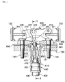
- a first embodiment of the invention includes a guide pipe 510 for guiding a brake cable 400 out of a drum brake fixed on a back plate 600.
- the back plate 600 is not formed of a superposed-steel plate but is formed of a steel sheet, which is fixed on a brake fixing part 150 (e. g., non-rotatable part on an axle member of the vehicle) by bolts 140, 140, 141, 141. Simultaneously, an anchor 200 is firmly fixed to the brake fixing part 150 by the bolts 140, 140.
- a brake fixing part 150 e. g., non-rotatable part on an axle member of the vehicle
- the guide pipe 510 is fixed on a guide pipe fixing portion 601 on the back plate 600, wherein the guide pipe fixing portion 601 has an insertion hole 602 for the insertion of the guide pipe 510 as well as a funnel shape portion protruding into a notched groove 151 of the brake fixing part 150.
- One end of the guide pipe 510 penetrates through the insertion hole 602 of the back plate 600 from the brake fixing part 150 side, and an overhanging or expanded portion 511 integrally formed on the intermediate portion thereof contacts a back of the guide pipe fixing portion 601.
- the widened end 512 of the guide pipe 510 may be positioned in a pocket of the guide pipe fixing portion 601 on the back plate 600. Hence, the widened end 512 of the guide pipe 510 does not need to be projected out from the anchor seat 202 of the anchor 200 toward the mechanical expander 300 unlike the conventional art. Therefore, the range of effective stroke of the brake cable 400 is increased. Accordingly, this structure is effective even if the distance from the brake fixing portion to the brake shoe center in the width direction, i.e., brake off-set, is short.
- the large diameter portion of the casing cap 431 of the outer casing 430 contacts the outer opening end surface of the guide pipe 510 and at the same time the small diameter top portion thereof fits into the bore of the guide pipe 510.
- the brake cable 400 is fixed on the guide pipe 510 by a wire spring clip 440.
- the brake cable 400 is securely affixed once properly attached to the operational end (not shown) of the brake cable 400 on the corresponding member. Therefore, the casing cap 431 may be press fit into the bore of the guide pipe 510 instead of using the spring clip 440.
- the diameter of a through hole 210 formed on the anchor seat 202 of the anchor 200 only needs to let penetrate through the inner cable 410 with the cable end nipple 420; thus it may be designed smaller, thereby further reducing the size of the anchor seat 202.
- the overhanging portion 511 of the guide pipe 510 may be formed by expanding the intermediate portion of the guide pipe 510 outwardly. Instead of the overhanging portion 511 an independent flat washer-like ring may be jointed over the guide pipe 510 so as to add the large diameter overhanging portion on the guide pipe 510. Besides the above-described means to fix the guide pipe 510 on the back plate 600, the guide pipe 510 may be fixed by other suitable means such as being welded to the back plate 600.
- the guide pipe fixing portion 601 on the back plate 600 may be designed to be a flat, where a diameter of the inner cable through hole 210 of the anchor 200 may be made large to store the widened end 512 of the guide pipe 510.
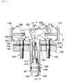
- Figure 3 shows a case where a back plate is configured in combination of and superposing an independently formed back plate body 700 superimposed on independent back plate stiffener 705 as a reinforcing plate supporting the back plate body 700.
- This second embodiment describes a case in which a spacer 800 is sandwiched between the brake fixing part 150 and the back plate stiffener 705, where the anchor 200, the back plate body 700, the back plate stiffener 705, and the spacers 800, 800 are fixed on the brake fixing part 150 by the bolts 140, 140.
- the spacers 800, 800 may be omitted without substantially reducing the effectiveness.
- the guide pipe fixing portion 706 for the guide pipe 520 in this second embodiment is different from the first embodiment in that the guide pipe fixing portion 706 is formed only on the back plate stiffener 705. That is, the guide pipe fixing portion 706 is positioned in a space between two spacers 800 and 800 and is designed to be a funnel shape portion protruding toward the brake fixing part 150. Further, the guide pipe insertion hole 707 is opened on the back plate stiffener 705 for the installation of the guide pipe 520. A portion of the back plate body 700 adjacent to the guide pipe insertion hole 707 is flat and has a through hole 703 for letting an inner cable 410 with a cable end nipple 420 penetrated therethrough.
- One end of the guide pipe 520 penetrates through the insertion hole 707 of the back plate stiffener 705 from the brake fixing part 150 side, and an overhanging portion 521 contacts a back of the guide pipe fixing portion 706.
- the widened end 522 of the guide pipe 520 may be positioned in the pocket of the guide pipe fixing portion 706 on the back plate stiffener 705. Hence, the widened end 522 of the guide pipe 520 does not need to project out from the anchor seat 202 of the anchor 200 toward the mechanical expander unlike in the conventional art.
- a funnel shape portion may be formed on the back plate body 700 for fixing the guide pipe 520, and alternatively, funnel shape portions may be formed both on the back plate body 700 and the back plate stiffener 705 for fixing the guide pipe 520 without difficulty.
- the above-described embodiments employ a brake cable mounting structure for a duo-servo (DS) type drum brake device where one adjacent facing ends of a pair of brake shoes 110, 120 are supported by the anchor 200, while the other adjacent facing ends thereof are connected via the adjuster 130.
- this invention is not limited to the application in the DS type.
- a fixed anchor as shown in the German Utility Mode Gazette No. DE7116427 may be employed instead of the conventional adjuster 130 as shown in Figure 4, which enables the brake cable mounting structure of this invention to be used in a leading-trailing (LT) type drum brake device.
- the brake cable fixing device of this invention may be applied in a dual mode drum brake as shown in the U.S. Patent No. 5720367 which functions like the LT type drum brake when a service brake is in operation but functions like the DS type when a parking brake is in operation.
- the brake cable mounting structure of this invention is applicable to any drum brake device with the mechanical expander 300 and the guide pipe 510, 520.
- a through hole for the inner cable with the cable end nipple opened on the anchor seat may be made smaller which also reduces the size of the anchor.
Landscapes
- Engineering & Computer Science (AREA)
- General Engineering & Computer Science (AREA)
- Mechanical Engineering (AREA)
- Braking Arrangements (AREA)
- Flexible Shafts (AREA)
Abstract
Description
Claims (6)
- A brake cable mounting structure for a drum brake comprising:a mechanical expander (300) having an input force portion (322), said expander (300) being disposed adjacent to a pair of adjacent facing ends of brake shoes (110,120) moveably mounted on a back plate (600;700) of a back plate structure so as to actuate said brake shoes (110,120);a brake cable (400) having an inner cable (410) connected with said input force portion (322) of said mechanical expander (300) and having an outer casing (430); anda guide pipe (510;520) for guiding said inner cable (410) to pass out of said drum brake, said outer casing (430) being attached to said guide pipe (510;520),wherein said guide pipe (510;520) is fixed on said back plate structure.
- The brake cable mounting structure for a drum brake as claimed in claim 1 wherein
a guide pipe fixing portion (601;706) of said back plate structure is designed to be a convex shape toward a brake fixing part side. - The brake cable mounting structure for a drum brake as claimed in claim 1 or 2 whereinsaid guide pipe (510;520) penetrates through a guide pipe insertion hole (602;707) of said back plate structure and projects outwardly from said guide pipe fixing portion (601;706),an expanded portion (511;521) provided on an intermediate portion of said guide pipe (510;520) contacts said back plate structure at said brake fixing part side,an outwardly projected end tip of said guide pipe (510;520) is formed to be a widened end (512;522), andsaid guide pipe (510;520) is fixed on said back plate structure by being secured between said expanded portion (511;521) and said widened end (512;522).
- The brake cable mounting structure for a drum brake as claimed in any one of claims 1-3, wherein
said back plate structure is configured as an integrated structure comprising an independently formed back plate body (700) superposing a back plate stiffener (705). - The brake cable mounting structure for a drum brake as claimed in any one of claims 1-3, wherein
said back plate structure is formed by a back plate body (600). - The brake cable mounting structure for a drum brake as claimed in one of claims 1-5, wherein
an anchor (200) supporting one adjacent ends of both brake shoes (110,120) is positioned adjacent to said mechanical expander (300).
Applications Claiming Priority (2)
| Application Number | Priority Date | Filing Date | Title |
|---|---|---|---|
| JP35816599A JP2001173694A (en) | 1999-12-16 | 1999-12-16 | Brake cable attachment device for drum brake |
| JP35816599 | 1999-12-16 |
Publications (2)
| Publication Number | Publication Date |
|---|---|
| EP1108917A2 true EP1108917A2 (en) | 2001-06-20 |
| EP1108917A3 EP1108917A3 (en) | 2002-01-02 |
Family
ID=18457884
Family Applications (1)
| Application Number | Title | Priority Date | Filing Date |
|---|---|---|---|
| EP00127723A Withdrawn EP1108917A3 (en) | 1999-12-16 | 2000-12-18 | Brake cable mounting structure for a drum brake |
Country Status (3)
| Country | Link |
|---|---|
| US (1) | US6412609B2 (en) |
| EP (1) | EP1108917A3 (en) |
| JP (1) | JP2001173694A (en) |
Cited By (1)
| Publication number | Priority date | Publication date | Assignee | Title |
|---|---|---|---|---|
| EP1808614A1 (en) * | 2006-01-11 | 2007-07-18 | Nisshinbo Industries, Inc. | Mechanical brake actuator |
Families Citing this family (9)
| Publication number | Priority date | Publication date | Assignee | Title |
|---|---|---|---|---|
| JP4540891B2 (en) | 2001-07-13 | 2010-09-08 | 豊生ブレーキ工業株式会社 | Parking brake |
| JP2005337327A (en) * | 2004-05-25 | 2005-12-08 | Advics:Kk | Drum brake device |
| US7264134B2 (en) | 2004-08-24 | 2007-09-04 | Tulp David W | Combination coaster and sleeve apparatus |
| US20080149434A1 (en) * | 2006-11-29 | 2008-06-26 | Akebono Corporation (North America) | Parking brake and actuator mechanism |
| US8267227B2 (en) | 2008-07-22 | 2012-09-18 | Akebono Brake Corporation | Lever assembly featuring blind cable assembly |
| DE102014204769A1 (en) * | 2013-12-06 | 2015-06-11 | Continental Teves Ag & Co. Ohg | Electromotive operable drum brake module |
| DE102017214938B4 (en) * | 2016-08-31 | 2020-09-03 | Mando Corporation | Electronic parking brake |
| IT201600105859A1 (en) | 2016-10-20 | 2018-04-20 | Freni Brembo Spa | Implementation assembly of a parking brake |
| WO2019161916A1 (en) * | 2018-02-23 | 2019-08-29 | Continental Teves Ag & Co. Ohg | Electric parking brake actuator mounting assembly |
Citations (1)
| Publication number | Priority date | Publication date | Assignee | Title |
|---|---|---|---|---|
| JPH06337027A (en) | 1993-05-27 | 1994-12-06 | Nisshinbo Ind Inc | Mechanical drum brake device |
Family Cites Families (12)
| Publication number | Priority date | Publication date | Assignee | Title |
|---|---|---|---|---|
| DE696200C (en) * | 1939-07-14 | 1941-03-06 | Porsche Kg | Shoe brake, especially for motor vehicles |
| DE3428134C2 (en) | 1984-07-31 | 1994-03-31 | Teves Gmbh Alfred | Brake cable attachment |
| DE3428135A1 (en) | 1984-07-31 | 1986-02-13 | Alfred Teves Gmbh, 6000 Frankfurt | INNER JAW BRAKE |
| DE8435833U1 (en) * | 1984-12-07 | 1985-04-18 | Maschinenbau Knott Eggstätt Ing. Valentin Knott, 8201 Eggstätt | BRAKE CABLE FASTENING |
| JPS6298034A (en) * | 1985-10-24 | 1987-05-07 | Mazda Motor Corp | Drum brake |
| US5062504A (en) * | 1989-05-05 | 1991-11-05 | General Motors Corporation | Drum brake assembly having parking brake actuator adjuster with automatic brake adjustment during the service braking mode of operation |
| US5322145A (en) * | 1989-08-29 | 1994-06-21 | Kelsey-Hayes Company | Drum brake operating mechanism |
| US5085296A (en) * | 1990-08-23 | 1992-02-04 | Allied-Signal Inc. | Mechanically actuated brake with automatic adjustment |
| JP3146400B2 (en) * | 1993-06-24 | 2001-03-12 | 日清紡績株式会社 | Cable connection method for drum brake |
| DE4327557B4 (en) | 1993-08-17 | 2004-08-26 | Continental Teves Ag & Co. Ohg | Duo-servo parking brake for motor vehicles |
| DE29512287U1 (en) * | 1995-07-29 | 1995-09-28 | WAP Fahrzeugtechnik GmbH, 33106 Paderborn | drum brake |
| JPH1137189A (en) * | 1997-07-17 | 1999-02-09 | Nisshinbo Ind Inc | Actuator of drum brake |
-
1999
- 1999-12-16 JP JP35816599A patent/JP2001173694A/en not_active Withdrawn
-
2000
- 2000-12-18 US US09/737,756 patent/US6412609B2/en not_active Expired - Fee Related
- 2000-12-18 EP EP00127723A patent/EP1108917A3/en not_active Withdrawn
Patent Citations (1)
| Publication number | Priority date | Publication date | Assignee | Title |
|---|---|---|---|---|
| JPH06337027A (en) | 1993-05-27 | 1994-12-06 | Nisshinbo Ind Inc | Mechanical drum brake device |
Cited By (2)
| Publication number | Priority date | Publication date | Assignee | Title |
|---|---|---|---|---|
| EP1808614A1 (en) * | 2006-01-11 | 2007-07-18 | Nisshinbo Industries, Inc. | Mechanical brake actuator |
| CN101000076B (en) * | 2006-01-11 | 2010-09-01 | 日清纺绩株式会社 | Mechanical brake actuator |
Also Published As
| Publication number | Publication date |
|---|---|
| EP1108917A3 (en) | 2002-01-02 |
| US6412609B2 (en) | 2002-07-02 |
| JP2001173694A (en) | 2001-06-26 |
| US20010004035A1 (en) | 2001-06-21 |
Similar Documents
| Publication | Publication Date | Title |
|---|---|---|
| JP2018528363A (en) | Disc brake and brake pad set for commercial vehicles | |
| US6412609B2 (en) | Brake cable mounting structure for a drum brake | |
| EP1174627B1 (en) | Brake cable connecting apparatus for drum brake | |
| JP3341147B2 (en) | Drum brake device | |
| US6325183B2 (en) | Brake cable mounting structure for a drum brake | |
| US6766887B2 (en) | Dual mode type drum brake device | |
| US3554330A (en) | Drum brakes | |
| US6742633B1 (en) | Linkage for joining a lever to a brake cable | |
| US6877590B2 (en) | Dual mode drum brake | |
| JP2002147506A (en) | Drum brake with automatic shoe clearance adjustment | |
| US20060075844A1 (en) | Brake cable connecting apparatus for a drum brake device | |
| US5096027A (en) | Drum brake | |
| KR100265512B1 (en) | Brake lining automatic adjustment device of car | |
| JPS628439Y2 (en) | ||
| JPH09222142A (en) | Drum brake | |
| KR20020089073A (en) | Drum brake | |
| JPS639789Y2 (en) | ||
| JPH06300063A (en) | Caliper body for vehicle disc brakes | |
| JP3553590B2 (en) | Drum brake actuator | |
| JP4540836B2 (en) | Drum brake | |
| JPH0738763U (en) | Duo servo type drum brake | |
| JPH0515625Y2 (en) | ||
| JPH10220503A (en) | Anchor device for drum brake | |
| JP4530594B2 (en) | Brake device cable introduction structure | |
| JPH0527719Y2 (en) |
Legal Events
| Date | Code | Title | Description |
|---|---|---|---|
| PUAI | Public reference made under article 153(3) epc to a published international application that has entered the european phase |
Free format text: ORIGINAL CODE: 0009012 |
|
| AK | Designated contracting states |
Kind code of ref document: A2 Designated state(s): AT BE CH CY DE DK ES FI FR GB GR IE IT LI LU MC NL PT SE TR Kind code of ref document: A2 Designated state(s): DE GB |
|
| AX | Request for extension of the european patent |
Free format text: AL;LT;LV;MK;RO;SI |
|
| PUAL | Search report despatched |
Free format text: ORIGINAL CODE: 0009013 |
|
| AK | Designated contracting states |
Kind code of ref document: A3 Designated state(s): AT BE CH CY DE DK ES FI FR GB GR IE IT LI LU MC NL PT SE TR |
|
| AX | Request for extension of the european patent |
Free format text: AL;LT;LV;MK;RO;SI |
|
| RIC1 | Information provided on ipc code assigned before grant |
Free format text: 7F 16D 65/09 A, 7F 16D 65/22 B |
|
| 17P | Request for examination filed |
Effective date: 20020607 |
|
| AKX | Designation fees paid |
Free format text: DE GB |
|
| STAA | Information on the status of an ep patent application or granted ep patent |
Free format text: STATUS: THE APPLICATION IS DEEMED TO BE WITHDRAWN |
|
| 18D | Application deemed to be withdrawn |
Effective date: 20040701 |