EP1808403A2 - Industrial vehicle with a removable power supply unit - Google Patents
Industrial vehicle with a removable power supply unit Download PDFInfo
- Publication number
- EP1808403A2 EP1808403A2 EP06027087A EP06027087A EP1808403A2 EP 1808403 A2 EP1808403 A2 EP 1808403A2 EP 06027087 A EP06027087 A EP 06027087A EP 06027087 A EP06027087 A EP 06027087A EP 1808403 A2 EP1808403 A2 EP 1808403A2
- Authority
- EP
- European Patent Office
- Prior art keywords
- supply unit
- power supply
- truck
- battery
- fixing
- Prior art date
- Legal status (The legal status is an assumption and is not a legal conclusion. Google has not performed a legal analysis and makes no representation as to the accuracy of the status listed.)
- Withdrawn
Links
Images
Classifications
-
- B—PERFORMING OPERATIONS; TRANSPORTING
- B66—HOISTING; LIFTING; HAULING
- B66F—HOISTING, LIFTING, HAULING OR PUSHING, NOT OTHERWISE PROVIDED FOR, e.g. DEVICES WHICH APPLY A LIFTING OR PUSHING FORCE DIRECTLY TO THE SURFACE OF A LOAD
- B66F9/00—Devices for lifting or lowering bulky or heavy goods for loading or unloading purposes
- B66F9/06—Devices for lifting or lowering bulky or heavy goods for loading or unloading purposes movable, with their loads, on wheels or the like, e.g. fork-lift trucks
- B66F9/075—Constructional features or details
- B66F9/07513—Details concerning the chassis
- B66F9/07531—Battery compartments
- B66F9/07536—Battery stoppers, i.e. means to hold battery in position
-
- B—PERFORMING OPERATIONS; TRANSPORTING
- B60—VEHICLES IN GENERAL
- B60K—ARRANGEMENT OR MOUNTING OF PROPULSION UNITS OR OF TRANSMISSIONS IN VEHICLES; ARRANGEMENT OR MOUNTING OF PLURAL DIVERSE PRIME-MOVERS IN VEHICLES; AUXILIARY DRIVES FOR VEHICLES; INSTRUMENTATION OR DASHBOARDS FOR VEHICLES; ARRANGEMENTS IN CONNECTION WITH COOLING, AIR INTAKE, GAS EXHAUST OR FUEL SUPPLY OF PROPULSION UNITS IN VEHICLES
- B60K1/00—Arrangement or mounting of electrical propulsion units
- B60K1/04—Arrangement or mounting of electrical propulsion units of the electric storage means for propulsion
-
- B—PERFORMING OPERATIONS; TRANSPORTING
- B60—VEHICLES IN GENERAL
- B60Y—INDEXING SCHEME RELATING TO ASPECTS CROSS-CUTTING VEHICLE TECHNOLOGY
- B60Y2200/00—Type of vehicle
- B60Y2200/10—Road Vehicles
- B60Y2200/15—Fork lift trucks, Industrial trucks
Definitions
- the invention relates to an industrial truck with an exchangeable power supply unit and a device for fixing the replaceable power supply unit in at least one direction of movement.
- interchangeable power units are often used instead of permanently installed devices such as internal combustion engines in combination with fuel tanks.
- these can be called power packs, i.
- Devices which have mostly similar dimensions as a replaceable battery and in which a fuel tank and a device for generating electrical energy from the fuel, in particular a fuel cell unit, are combined in one unit. If the energy reserves of the energy supply unit are exhausted, it can be directly exchanged for another energy supply unit with full inventories, so that the downtime of the truck is minimized.
- the power supply unit is usually arranged in a separate area of the truck, which is referred to as a battery compartment.
- the dimensions of the battery compartment are as compact as possible in order to make optimal use of the space available in the truck.
- it in order to enable a rapid change of the energy supply unit, it must be significantly larger than the largest energy supply unit to be introduced, since otherwise it will tilt too easily.
- the battery compartment must have certain minimum dimensions. Due to the distance of the power supply unit from the side walls of the battery compartment, the power supply unit can move in abrupt vehicle movements in relation to the battery compartment and strike for example on one of the side walls, which can lead to damage of the truck and / or the power supply unit. As the distance to the front or rear side walls of the battery compartment is particularly is large, especially movements of the power supply unit in the vehicle longitudinal direction are dangerous and must be prevented.
- the invention is therefore an object of the invention to provide an industrial truck with a replaceable power supply unit and a device for fixing the replaceable power supply unit in at least one direction of movement, with little effort a simple replacement of the power supply unit, possible independent of the dimensions of the power supply unit.
- This object is achieved in that the device for fixing the power supply unit is designed such that the power supply unit is automatically fixed. The time-consuming and error-prone fixation of the power supply unit by hand is eliminated.
- the device has at least one latching element, in particular a snap-in hook, arranged in the bottom area and / or at least one latching element, preferably oriented parallel to the vehicle longitudinal axis, of a battery compartment.
- the wall is any outer boundary of the battery compartment, especially the ceiling to see, even if it is broken structures such as grids or perforated plates.
- Latching elements such as latching hooks or latching lugs, are elements that allow in one direction a largely unrestrained movement, while in the opposite direction no movement is possible. The use of such locking elements thus allows desired movements, such as the insertion of the power supply unit, and prevents the unwanted countermovement, such as slipping out of the power supply unit.
- a movement of the battery parallel to the vehicle longitudinal direction is particularly harmful and can be particularly well prevented by arranged in the bottom area and / or in the direction parallel to the direction of travel walls of the battery compartment locking elements, as these compared to the orthogonal aligned to the direction of travel front and rear walls are usually arranged very close to the battery and are well suited by their orientation for receiving forces in the vehicle longitudinal direction.
- an attachment in the bottom area is advantageous because this, in order to accommodate the weight of the battery, is usually carried out particularly stable.
- the device it is advantageous for the device to have a plurality of latching elements, in particular snap-in hooks, arranged in the bottom area and / or at least one wall of a battery compartment oriented preferably parallel to the vehicle longitudinal axis.
- a plurality of latching elements in particular snap-in hooks, arranged in the bottom area and / or at least one wall of a battery compartment oriented preferably parallel to the vehicle longitudinal axis.
- the further, in the opposite direction effective element for fixing the power supply unit can not only be a locking element, but for example, a fixed stop or a correspondingly designed wall of the battery compartment.
- fixation of the power supply unit is automatically solvable. This allows a quick, easy and safe removal of the power supply unit.
- the device can be actuated by means of spring force.
- a spring force operation allows for easy setup and operation independent of in-vehicle and / or external power sources.
- the power supply unit is designed as a battery. Batteries are the simplest and most cost-effective power supply units for industrial trucks.
- the energy supply unit is designed as a structural unit of fuel cell unit and energy storage.
- Such units which are often used in exchange for removable batteries, often have similar dimensions as removable batteries.
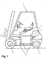
- the 1 shows a counterbalance forklift 1 with a so-called battery compartment 2.
- the battery compartment 2 is a battery 3 as an example of a replaceable power supply unit.
- the battery 3 can be removed from the vehicle 1, for example, by being lifted by another forklift and transported away laterally.
- the battery compartment 2 is arranged between the front axle 4 and the rear axle 5 and can be closed by means of a flap, not shown here.
- the battery compartment 2 is slightly larger than the outer dimensions of the largest power supply unit to be used, given the limited space in the forklift 1 but not larger than absolutely necessary.
- the battery 3 is therefore fixed in vehicles according to the prior art by means of operable by the operator holding devices, such as pivoting lever.
- the operator holding devices such as pivoting lever.
- a device 7 according to the invention for the automatic fixation of the battery 3 is arranged in the bottom 6 of the battery compartment 2.
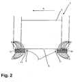
- the device 7 for fixing the battery 3 is shown in Figure 2 in a detailed view of the battery compartment 2, wherein a section along the vehicle longitudinal axis is shown.
- the device 7 consists of a plurality of latching hooks 8, which are arranged and guided in the bottom 6 of the battery compartment 2 and are pushed out by means of springs 9 upwards. If the battery 3 is discontinued, the locking hooks 8 located under the battery 3 are pressed into the bottom 6.
- the battery 3 is the first settling in a position in which a movement is possible, for example, because the battery 3 is placed exactly on the latching hook 8, that both edges 10 of the battery 3 to rest exactly on the tips of latching hooks 8 come, so in the first movement of the battery 3, for example during a start-up or braking, the battery 3 slip so far that on one side of the locking hooks 8 are released and the battery 3 can not perform any movement in the opposite direction.
- the simple mechanism shown can be selected.
- a device for removing the fixation may be advantageous. In the illustrated embodiment, this can be achieved by lowering the bottom plate 11, on which the springs 9 are supported.
- an unlocking mechanism can be actuated by an operator, or the lowering is coupled to the opening of the flap, not shown, with which the battery compartment 2 is closed while driving.
- latching hooks 8 are expediently arranged depending on the dimensions of the energy supply units used, that is to say, for example, as shown in FIG. 2, in rows which are oriented orthogonally to the vehicle longitudinal axis or also stepped.
- other locking elements are conceivable, such as, for example, pivotally mounted on one side plates, which are placed by means of spring force.
- torsion springs are also conceivable, which are particularly advantageous in pivotable locking elements.
Abstract
Description
Die Erfindung betrifft ein Flurförderzeug mit einer austauschbaren Energieversorgungseinheit und einer Vorrichtung zur Fixierung der austauschbaren Energieversorgungseinheit in mindestens einer Bewegungsrichtung.The invention relates to an industrial truck with an exchangeable power supply unit and a device for fixing the replaceable power supply unit in at least one direction of movement.
Zur Energieversorgung von Flurförderzeugen werden häufig anstelle fest installierter Vorrichtungen, wie beispielsweise Verbrennungsmotoren in Kombination mit Treibstofftanks, austauschbaren Energieversorgungseinheiten verwendet. Neben den weit verbreiteten Wechselbatterien können dies so genannte Power Packs, d.h. Vorrichtungen, die zumeist ähnliche Abmessungen wie eine Wechselbatterie aufweisen und bei denen ein Brennstofftank sowie eine Vorrichtung zur Erzeugung elektrischer Energie aus dem Brennstoff, insbesondere eine Brennstoffzelleneinheit, in einer Baueinheit zusammengefasst sind. Sind die Energievorräte der Energieversorgungseinheit erschöpft, kann diese direkt gegen eine weitere Energieversorgungseinheit mit vollen Vorräten ausgetauscht werden, so dass die Stillstandszeit des Flurförderzeugs minimiert wird. Die Energieversorgungseinheit ist dazu zumeist in einem abgetrennten Bereich des Flurförderzeugs angeordnet, der als Batteriefach bezeichnet wird.For powering trucks, interchangeable power units are often used instead of permanently installed devices such as internal combustion engines in combination with fuel tanks. In addition to the widely used replaceable batteries, these can be called power packs, i. Devices which have mostly similar dimensions as a replaceable battery and in which a fuel tank and a device for generating electrical energy from the fuel, in particular a fuel cell unit, are combined in one unit. If the energy reserves of the energy supply unit are exhausted, it can be directly exchanged for another energy supply unit with full inventories, so that the downtime of the truck is minimized. The power supply unit is usually arranged in a separate area of the truck, which is referred to as a battery compartment.
Das Batteriefach ist in seinen Abmessungen möglichst kompakt, um den knappen im Flurförderzeug zur Verfügung stehenden Platz optimal auszunutzen. Um einen zügigen Wechsel der Energieversorgungseinheit zu ermöglichen, muss es jedoch deutlich größer als die größte einzuführende Energieversorgungseinheit sein, da diese ansonsten zu leicht verkantet. Auch um eine hinreichende Belüftung der Energieversorgungseinheit sicherzustellen, muss das Batteriefach gewisse Mindestmaße besitzen. Aufgrund des Abstandes der Energieversorgungseinheit von den Seitenwänden des Batteriefachs kann sich die Energieversorgungseinheit bei abrupten Fahrzeugbewegungen in Relation zu dem Batteriefach bewegen und beispielsweise an eine der Seitenwände anschlagen, was zu einer Beschädigung des Flurförderzeugs und/oder der Energieversorgungseinheit führen kann. Da der Abstand zu den vorderen beziehungsweise hinteren Seitenwänden des Batteriefachs besonders groß ist, sind besonders Bewegungen der Energieversorgungseinheit in Fahrzeuglängsrichtung gefährlich und müssen unterbunden werden.The dimensions of the battery compartment are as compact as possible in order to make optimal use of the space available in the truck. However, in order to enable a rapid change of the energy supply unit, it must be significantly larger than the largest energy supply unit to be introduced, since otherwise it will tilt too easily. Also, to ensure adequate ventilation of the power supply unit, the battery compartment must have certain minimum dimensions. Due to the distance of the power supply unit from the side walls of the battery compartment, the power supply unit can move in abrupt vehicle movements in relation to the battery compartment and strike for example on one of the side walls, which can lead to damage of the truck and / or the power supply unit. As the distance to the front or rear side walls of the battery compartment is particularly is large, especially movements of the power supply unit in the vehicle longitudinal direction are dangerous and must be prevented.
Um unerwünschte Bewegungen der Energieversorgungseinheit zu vermeiden, wird diese bei Fahrzeugen nach dem Stand der Technik zumeist mittels geeigneter Vorrichtungen fixiert. Bekannt ist die Verwendung von Gurten oder beweglichen Halterungen, die von der Bedienperson von einer Ruheposition in eine Halteposition gebracht werden und so die Energieversorgungseinheit fixieren. Nachteilig an diesen Vorrichtungen ist jedoch, dass die Bedienperson nach dem Einführen der Energieversorgungseinheit diese Haltevorrichtungen anbringen und ggf. sichern muss. Dies erfordert zusätzliche Zeit und Aufwand und bringt, wenn vergessen wird, die Vorrichtungen zu betätigen, erhebliche Sicherheitsrisiken mit sich.In order to avoid unwanted movements of the power supply unit, this is usually fixed in vehicles according to the prior art by means of suitable devices. Known is the use of straps or movable brackets, which are brought by the operator from a rest position to a holding position, thus fixing the power supply unit. A disadvantage of these devices, however, is that the operator after the introduction of the power supply unit attach these fixtures and possibly secure. This requires additional time and effort and, if forgetting to operate the devices, entails significant security risks.
Fest installierte Haltevorrichtungen hingegen, beispielsweise am Boden des Batteriefachs angeordnete Halteleisten, erfordern große Sorgfalt beim Einbringen der Energieversorgungseinheit. Zudem ist eine Verwendung von Energieversorgungseinheiten mit unterschiedlichen Abmessungen nur schwer oder gar nicht möglich, da die fest installierten Halterungen nur für eine Größe der Energieversorgungseinheit ausgelegt sind und ansonsten entweder nicht ausreichend an der Energieversorgungseinheit anliegen und somit keine ausreichende Haltewirkung besitzen, oder aber zu eng sind und diese keinen Platz hat.By contrast, permanently installed holding devices, for example holding strips arranged at the bottom of the battery compartment, require great care in introducing the energy supply unit. In addition, a use of power supply units with different dimensions is difficult or impossible, since the fixed brackets are designed only for one size of the power supply unit and otherwise either insufficiently applied to the power supply unit and thus have no sufficient holding effect, or too tight and this has no place.
Der Erfindung liegt daher die Aufgabe zugrunde, ein Flurförderzeug mit einer austauschbaren Energieversorgungseinheit und einer Vorrichtung zur Fixierung der austauschbaren Energieversorgungseinheit in mindestens einer Bewegungsrichtung zu schaffen, das mit geringem Aufwand einen einfachen Austausch der Energieversorgungseinheit, möglichst unabhängig von den Abmessungen der Energieversorgungseinheit, ermöglicht.The invention is therefore an object of the invention to provide an industrial truck with a replaceable power supply unit and a device for fixing the replaceable power supply unit in at least one direction of movement, with little effort a simple replacement of the power supply unit, possible independent of the dimensions of the power supply unit.
Diese Aufgabe wird erfindungsgemäß dadurch gelöst, dass die Vorrichtung zur Fixierung der Energieversorgungseinheit derart ausgebildet ist, dass die Energieversorgungseinheit selbsttätig fixierbar ist. Die zeitaufwändige und fehleranfällige Fixierung der Energieversorgungseinheit von Hand entfällt.This object is achieved in that the device for fixing the power supply unit is designed such that the power supply unit is automatically fixed. The time-consuming and error-prone fixation of the power supply unit by hand is eliminated.
Vorteilhafterweise weist die Vorrichtung mindestens ein im Bodenbereich und/oder mindestens einer, vorzugsweise parallel zur Fahrzeuglängsachse orientierten Wand eines Batteriefachs angeordnetes Rastelement, insbesondere einen Rasthaken, auf. Als Wand ist jede äußere Begrenzung des Batteriefachs, insbesondere auch die Decke, zu sehen, auch wenn es sich dabei um durchbrochene Konstruktionen wie beispielsweise Gitter oder Lochbleche handelt. Rastelemente, wie beispielsweise Rasthaken oder Rastnasen, sind Elemente, die in eine Richtung eine weitgehend ungehemmte Bewegung gestatten, während in der Gegenrichtung keine Bewegung möglich ist. Die Verwendung derartiger Rastelemente ermöglicht somit gewünschte Bewegungen, wie das Einführen der Energieversorgungseinheit, und verhindert die unerwünschte Gegenbewegung, wie beispielsweise das Herausrutschen der Energieversorgungseinheit. Eine Bewegung der Batterie parallel zur Fahrzeuglängsrichtung, beispielsweise beim Beschleunigen und/oder Bremsen, ist besonders schädlich und kann durch im Bodenbereich und/oder in den parallel zur Fahrtrichtung orientierten Wänden des Batteriefachs angeordnete Rastelemente besonders gut unterbunden werden, da diese im Vergleich zu den orthogonal zur Fahrtrichtung ausgerichteten Vorder- beziehungsweise Rückwänden zumeist sehr nah an der Batterie angeordnet sind und durch ihre Ausrichtung zur Aufnahme von Kräften in Fahrzeuglängsrichtung gut geeignet sind. Insbesondere eine Anbringung im Bodenbereich ist vorteilhaft, da dieser, um das Gewicht der Batterie aufzunehmen, zumeist besonders stabil ausgeführt ist.Advantageously, the device has at least one latching element, in particular a snap-in hook, arranged in the bottom area and / or at least one latching element, preferably oriented parallel to the vehicle longitudinal axis, of a battery compartment. The wall is any outer boundary of the battery compartment, especially the ceiling to see, even if it is broken structures such as grids or perforated plates. Latching elements, such as latching hooks or latching lugs, are elements that allow in one direction a largely unrestrained movement, while in the opposite direction no movement is possible. The use of such locking elements thus allows desired movements, such as the insertion of the power supply unit, and prevents the unwanted countermovement, such as slipping out of the power supply unit. A movement of the battery parallel to the vehicle longitudinal direction, for example when accelerating and / or braking, is particularly harmful and can be particularly well prevented by arranged in the bottom area and / or in the direction parallel to the direction of travel walls of the battery compartment locking elements, as these compared to the orthogonal aligned to the direction of travel front and rear walls are usually arranged very close to the battery and are well suited by their orientation for receiving forces in the vehicle longitudinal direction. In particular, an attachment in the bottom area is advantageous because this, in order to accommodate the weight of the battery, is usually carried out particularly stable.
Weiterhin ist es vorteilhaft, wenn die Vorrichtung mehrere im Bodenbereich und/oder mindestens einer, vorzugsweise parallel zur Fahrzeuglängsachse orientierten Wand eines Batteriefachs angeordnete Rastelemente, insbesondere Rasthaken, aufweist. Durch die Verwendung von mehreren, das heißt drei oder mehr Rastelementen wird sichergestellt, dass die Energieversorgungseinheit unabhängig von der Ausgangsposition sicher fixiert wird, da nur ein geringer Bewegungsweg bis zum Einrasten der Energieversorgungseinheit in die Rastelemente zur Verfügung steht und der Bewegungsweg zwischen den aktiven Rastelementen gering ist. Bei Verwendung verschiedener Energieversorgungseinheiten mit unterschiedlichen Abmessungen ist so zudem sichergestellt, dass jede Energieversorgungseinheit sicher fixiert wird.Furthermore, it is advantageous for the device to have a plurality of latching elements, in particular snap-in hooks, arranged in the bottom area and / or at least one wall of a battery compartment oriented preferably parallel to the vehicle longitudinal axis. By using several, that is, three or more locking elements ensures that the power supply unit is securely fixed regardless of the starting position, since only a small amount of movement is available until the energy supply unit engages in the locking elements and the path of movement between the active locking elements low is. When using different power supply units with different dimensions, this also ensures that each power supply unit is securely fixed.
Zweckmäßigerweise entspricht der Abstand zwischen einem Rastelement und einem weiteren, in Gegenrichtung wirksamen Element zum Fixieren der Energieversorgungseinheit, insbesondere mindestens einem weiteren Rastelement, annähernd einer der Hauptabmessungen der Energieversorgungseinheit. Dadurch wird eine Bewegung der Energieversorgungseinheit entlang der Achse der betroffenen Hauptabmessung, als beispielsweise in Längs- oder Querrichtung der Energieversorgungseinheit, praktisch vollständig verhindert. Das weitere, in Gegenrichtung wirksame Element zum Fixieren der Energieversorgungseinheit kann dabei nicht nur ein Rastelement sein, sondern beispielsweise auch ein fest installierter Anschlag oder eine entsprechend ausgelegte Wand des Batteriefachs.Conveniently, the distance between a locking element and another, effective in the opposite direction element for fixing the Energy supply unit, in particular at least one further latching element, approximately one of the main dimensions of the power supply unit. Thereby, a movement of the power supply unit along the axis of the affected main dimension, as for example in the longitudinal or transverse direction of the power supply unit, almost completely prevented. The further, in the opposite direction effective element for fixing the power supply unit can not only be a locking element, but for example, a fixed stop or a correspondingly designed wall of the battery compartment.
Weiterhin ist es zweckmäßig, wenn die Fixierung der Energieversorgungseinheit selbsttätig lösbar ist. Dadurch wird eine schnelle, einfache und sichere Entnahme der Energieversorgungseinheit ermöglicht.Furthermore, it is expedient if the fixation of the power supply unit is automatically solvable. This allows a quick, easy and safe removal of the power supply unit.
Es ist ebenso zweckmäßig, wenn die Fixierung der Energieversorgungseinheit durch Eingriff einer Bedienperson lösbar ist. Indem die Bedienperson gezielt die Fixierung aufhebt, wird ihr bewusst, dass die Energieversorgungseinheit ungesichert ist.It is also expedient if the fixing of the power supply unit by engagement of an operator is solvable. By the operator deliberately lifts the fix, she becomes aware that the power supply unit is unsecured.
Vorteilhafterweise ist die Vorrichtung mittels Federkraft betätigbar. Eine Betätigung mit Federkraft ermöglicht einen einfachen Aufbau und eine Betätigung unabhängig von fahrzeuginternen und/oder -externen Energiequellen.Advantageously, the device can be actuated by means of spring force. A spring force operation allows for easy setup and operation independent of in-vehicle and / or external power sources.
In einer zweckmäßigen Ausbildung der Erfindung ist die Energieversorgungseinheit als Batterie ausgebildet. Batterien sind die einfachsten und kostengünstigsten Energieversorgungseinheiten für Flurförderzeuge.In an expedient embodiment of the invention, the power supply unit is designed as a battery. Batteries are the simplest and most cost-effective power supply units for industrial trucks.
In einer weiteren zweckmäßigen Ausbildung der Erfindung ist die Energieversorgungseinheit als Baueinheit von Brennstoffzelleneinheit und Energiespeicher ausgebildet. Derartige Baueinheiten, die häufig im Tausch für Wechselbatterien verwendet werden, besitzen oft ähnliche Abmessungen wie Wechselbatterien.In a further expedient embodiment of the invention, the energy supply unit is designed as a structural unit of fuel cell unit and energy storage. Such units, which are often used in exchange for removable batteries, often have similar dimensions as removable batteries.
Weitere Vorteile und Einzelheiten der Erfindung werden im Folgenden anhand des in der Zeichnung dargestellten Ausführungsbeispiels näher erläutert. Gleiche Teile sind mit gleichen Bezugszeichen gekennzeichnet. Dabei zeigt
Figur 1- einen Gegengewichtsgabelstapler mit einem Batteriefach,
Figur 2- eine Detailansicht des Batteriefachs mit der erfindungsgemäßen Vorrichtung.
- FIG. 1
- a counterbalance forklift with a battery compartment,
- FIG. 2
- a detailed view of the battery compartment with the device according to the invention.
Figur 1 zeigt einen Gegengewichtsgabelstapler 1 mit einem so genannten Batteriefach 2. In dem Batteriefach 2 befindet sich eine Batterie 3 als Beispiel für eine austauschbare Energieversorgungseinheit. Die Batterie 3 kann aus dem Fahrzeug 1 entnommen werden, indem diese beispielsweise von einem weiteren Gabelstapler angehoben und seitlich abtransportiert wird. Das Batteriefach 2 ist zwischen Vorderachse 4 und Hinterachse 5 angeordnet und kann mittels einer hier nicht dargestellten Klappe verschlossen werden. Um das Einführen der Batterie 3 oder einer anderen austauschbaren Energieversorgungseinheit zu erleichtern, ist das Batteriefach 2 geringfügig größer als die Außenmaße der größten zu verwendenden Energieversorgungseinheit ausgeführt, angesichts der beengten Raumverhältnisse im Gabelstapler 1 aber nicht größer als unbedingt notwendig. Sowohl seitlich als auch in Fahrtrichtung (Pfeil A) wird die Batterie 3 daher bei Fahrzeugen nach dem Stand der Technik mittels von der Bedienperson betätigbarer Haltevorrichtungen, wie beispielsweise Schwenkhebel, fixiert. Im gezeigten Ausführungsbeispiel dagegen ist im Boden 6 des Batteriefachs 2 eine erfindungsgemäße Vorrichtung 7 zur selbsttätigen Fixierung der Batterie 3 angeordnet.1 shows a counterbalance forklift 1 with a so-called
Die Vorrichtung 7 zur Fixierung der Batterie 3 ist in Figur 2 in einer Detailansicht des Batteriefachs 2 dargestellt, wobei ein Schnitt entlang der Fahrzeuglängsachse gezeigt ist. Im Wesentlichen besteht die Vorrichtung 7 aus einer Vielzahl von Rasthaken 8, die im Boden 6 des Batteriefachs 2 angeordnet und geführt sind und mittels Federn 9 nach oben herausgedrückt werden. Wird die Batterie 3 abgesetzt, werden die unter der Batterie 3 befindlichen Rasthaken 8 in den Boden 6 hineingedrückt. Befindet sich die Batterie 3 beim ersten Absetzen in einer Position, in der eine Bewegung möglich ist, beispielsweise, weil die Batterie 3 genau so auf den Rasthaken 8 platziert ist, dass beide Kanten 10 der Batterie 3 genau auf den Spitzen von Rasthaken 8 zu ruhen kommen, so wird bei der ersten Bewegung der Batterie 3, beispielsweise bei einem Anfahr- oder Bremsvorgang, die Batterie 3 soweit verrutschen, dass auf einer Seite der oder die Rasthaken 8 freigegeben werden und die Batterie 3 keine Bewegung in der Gegenrichtung mehr ausführen kann. In der Figur sind aufgrund der geschnittenen Darstellung lediglich Rasthaken 8 gezeigt, die eine Bewegung der Batterie 3 in Fahrzeuglängsrichtung verhindern. Es können jedoch auch, vorzugsweise im mittleren Bereich B, Rasthaken 8 vorgesehen sein, die eine seitliche Bewegung der Batterie 3 hemmen.The
Bietet das Batteriefach 2 wie im gezeigten Ausführungsbeispiel nach oben hin genug Raum, um die Batterie 3 bei der Entnahme über die ausgefahrenen Rasthaken 8 hinweg bewegen zu können, kann der gezeigte einfache Mechanismus gewählt werden. Ist jedoch ein weites Anheben der Batterie 3 nicht möglich oder gewünscht, so kann eine Vorrichtung zur Aufhebung der Fixierung vorteilhaft sein. Im gezeigten Ausführungsbeispiel kann dies durch ein Absenken der Bodenplatte 11, auf der sich die Federn 9 abstützen, erreicht werden. Hierzu kann entweder von einer Bedienperson ein Entriegelungsmechanismus betätigt werden, oder aber die Absenkung ist mit der Öffnung der nicht dargestellten Klappe gekoppelt, mit der das Batteriefach 2 im Fahrbetrieb verschlossen wird.Provides the
Anstelle der mechanischen Federn 9 können selbstverständlich auch andere Federmechanismen Verwendung finden, insbesondere solche, die auf pneumatischen und/oder hydraulischen Elementen beruhen. Die Rasthaken 8 sind je nach Abmessungen der verwendeten Energieversorgungseinheiten zweckmäßig angeordnet, also beispielsweise, wie in Figur 2 gezeigt, in Reihen, die orthogonal zur Fahrzeuglängsachse orientiert sind oder auch gestuft. Anstelle der Rasthaken 8 sind auch andere Rastelemente denkbar, wie beispielsweise einseitig schwenkbar gelagerte Platten, die mittels Federkraft aufgestellt werden. Anstelle der gezeigten Schraubenfedern sind beispielsweise auch Torsionsfedern denkbar, die bei schwenkbaren Rastelementen besonders vorteilhaft sind.Of course, other spring mechanisms may be used instead of the mechanical springs 9, in particular those based on pneumatic and / or hydraulic elements. The latching hooks 8 are expediently arranged depending on the dimensions of the energy supply units used, that is to say, for example, as shown in FIG. 2, in rows which are oriented orthogonally to the vehicle longitudinal axis or also stepped. Instead of the latching
Claims (9)
Applications Claiming Priority (1)
| Application Number | Priority Date | Filing Date | Title |
|---|---|---|---|
| DE102006002243A DE102006002243A1 (en) | 2006-01-17 | 2006-01-17 | Truck with a replaceable power supply unit |
Publications (2)
| Publication Number | Publication Date |
|---|---|
| EP1808403A2 true EP1808403A2 (en) | 2007-07-18 |
| EP1808403A3 EP1808403A3 (en) | 2008-10-08 |
Family
ID=37898340
Family Applications (1)
| Application Number | Title | Priority Date | Filing Date |
|---|---|---|---|
| EP06027087A Withdrawn EP1808403A3 (en) | 2006-01-17 | 2006-12-29 | Industrial vehicle with a removable power supply unit |
Country Status (2)
| Country | Link |
|---|---|
| EP (1) | EP1808403A3 (en) |
| DE (1) | DE102006002243A1 (en) |
Cited By (3)
| Publication number | Priority date | Publication date | Assignee | Title |
|---|---|---|---|---|
| EP2298690A1 (en) * | 2009-09-21 | 2011-03-23 | STILL GmbH | Battery exchange system of an electric car |
| DE102019100454A1 (en) | 2018-12-31 | 2020-07-02 | Still Gmbh | Industrial truck |
| EP3677540A1 (en) | 2018-12-31 | 2020-07-08 | STILL GmbH | Industrial truck |
Citations (4)
| Publication number | Priority date | Publication date | Assignee | Title |
|---|---|---|---|---|
| DE4105023C1 (en) * | 1991-02-19 | 1992-07-16 | A. Raymond Kg, 7850 Loerrach, De | |
| DE9408233U1 (en) * | 1994-05-19 | 1994-07-14 | Gardena Kress & Kastner Gmbh | Container or insert for containers |
| FR2862035A1 (en) * | 2003-11-10 | 2005-05-13 | Linde Ag | Battery changing system for industrial truck, has receiving device including ramp coming in contact with battery pack, when truck is moved over device, to push pack on ramp for raising pack, where ramp is formed by roller path |
| DE102005025647A1 (en) * | 2005-06-03 | 2006-12-07 | Still Gmbh | Truck with laterally removable power supply unit |
-
2006
- 2006-01-17 DE DE102006002243A patent/DE102006002243A1/en not_active Withdrawn
- 2006-12-29 EP EP06027087A patent/EP1808403A3/en not_active Withdrawn
Patent Citations (4)
| Publication number | Priority date | Publication date | Assignee | Title |
|---|---|---|---|---|
| DE4105023C1 (en) * | 1991-02-19 | 1992-07-16 | A. Raymond Kg, 7850 Loerrach, De | |
| DE9408233U1 (en) * | 1994-05-19 | 1994-07-14 | Gardena Kress & Kastner Gmbh | Container or insert for containers |
| FR2862035A1 (en) * | 2003-11-10 | 2005-05-13 | Linde Ag | Battery changing system for industrial truck, has receiving device including ramp coming in contact with battery pack, when truck is moved over device, to push pack on ramp for raising pack, where ramp is formed by roller path |
| DE102005025647A1 (en) * | 2005-06-03 | 2006-12-07 | Still Gmbh | Truck with laterally removable power supply unit |
Cited By (4)
| Publication number | Priority date | Publication date | Assignee | Title |
|---|---|---|---|---|
| EP2298690A1 (en) * | 2009-09-21 | 2011-03-23 | STILL GmbH | Battery exchange system of an electric car |
| DE102010035818A1 (en) | 2009-09-21 | 2011-03-24 | Still Gmbh | Battery replacement system of an electric vehicle |
| DE102019100454A1 (en) | 2018-12-31 | 2020-07-02 | Still Gmbh | Industrial truck |
| EP3677540A1 (en) | 2018-12-31 | 2020-07-08 | STILL GmbH | Industrial truck |
Also Published As
| Publication number | Publication date |
|---|---|
| DE102006002243A1 (en) | 2007-07-19 |
| EP1808403A3 (en) | 2008-10-08 |
Similar Documents
| Publication | Publication Date | Title |
|---|---|---|
| DE202019001787U1 (en) | Removable plug-in module for material handling vehicles | |
| EP1686637B1 (en) | Arrangement of several energy storage unity in a vehicle | |
| DE102007061055B4 (en) | flap arrangement | |
| DE102006031461A1 (en) | Battery replacement system for a battery-operated truck | |
| EP2423152A1 (en) | Industrial truck with a battery holder compartment | |
| DE102017117726A1 (en) | Housing device for energy storage systems | |
| DE202008012144U1 (en) | Device for securing a battery in a battery compartment of a truck | |
| DE102011108199A1 (en) | Electric drive device for use in battery exchange device for electrical refueling of motor car, has electromotor interchanging refueling, and battery case defining battery exchange direction that is arranged parallel to force direction | |
| DE102009057014A1 (en) | Device for closing a lowerable chute of a luggage compartment | |
| EP1808403A2 (en) | Industrial vehicle with a removable power supply unit | |
| DE102005007584A1 (en) | Industrial truck e.g. fork-lift truck, has holding device for fixing power supply unit e.g. battery, in withdrawal direction and including spring and/or damping unit that operates in withdrawal direction by force on holding device | |
| EP3293393A1 (en) | Device and method for exchange of interchangeable components of a wind power plant | |
| DE19622694B4 (en) | Industrial truck with a battery compartment | |
| DE102009052371A1 (en) | Vehicle, has energy storage device with set of energy storage units, which are arranged and/or designed such that energy storage units are movable and/or deformable in non-destructive manner by force effect on vehicle | |
| DE102018211346A1 (en) | motor vehicle | |
| DE102017002249B4 (en) | Motor vehicle and vehicle body for a motor vehicle | |
| EP1205424B1 (en) | Industrial truck with a battery pack | |
| WO2021083721A1 (en) | Floor assembly for a motor vehicle, motor vehicle and method for producing a floor assembly | |
| DE102015000580A1 (en) | Electric energy storage and motor vehicle | |
| DE112010003875B4 (en) | Switch lock fitting and control device so as well as methods for producing a switch lock fitting and use of the produced switch lock fitting | |
| DE102013020292B4 (en) | Battery system for a truck | |
| DE102016103506A1 (en) | Connector holding structure | |
| DE102016115691A1 (en) | Rear vehicle floor structure | |
| DE102019204538A1 (en) | Gripping device and method for gripping a drive motor | |
| EP2534070A1 (en) | Slot gripper |
Legal Events
| Date | Code | Title | Description |
|---|---|---|---|
| PUAI | Public reference made under article 153(3) epc to a published international application that has entered the european phase |
Free format text: ORIGINAL CODE: 0009012 |
|
| AK | Designated contracting states |
Kind code of ref document: A2 Designated state(s): AT BE BG CH CY CZ DE DK EE ES FI FR GB GR HU IE IS IT LI LT LU LV MC NL PL PT RO SE SI SK TR |
|
| AX | Request for extension of the european patent |
Extension state: AL BA HR MK YU |
|
| PUAL | Search report despatched |
Free format text: ORIGINAL CODE: 0009013 |
|
| AK | Designated contracting states |
Kind code of ref document: A3 Designated state(s): AT BE BG CH CY CZ DE DK EE ES FI FR GB GR HU IE IS IT LI LT LU LV MC NL PL PT RO SE SI SK TR |
|
| AX | Request for extension of the european patent |
Extension state: AL BA HR MK RS |
|
| AKX | Designation fees paid | ||
| STAA | Information on the status of an ep patent application or granted ep patent |
Free format text: STATUS: THE APPLICATION IS DEEMED TO BE WITHDRAWN |
|
| 18D | Application deemed to be withdrawn |
Effective date: 20090409 |
|
| REG | Reference to a national code |
Ref country code: DE Ref legal event code: 8566 |