EP1808386A1 - Behälteranordnung für eine Anlage zum Waschen und/oder zum Dekontaminieren von Gegenständen, insbesondere Müllbehälter oder dergleichen - Google Patents
Behälteranordnung für eine Anlage zum Waschen und/oder zum Dekontaminieren von Gegenständen, insbesondere Müllbehälter oder dergleichen Download PDFInfo
- Publication number
- EP1808386A1 EP1808386A1 EP07000390A EP07000390A EP1808386A1 EP 1808386 A1 EP1808386 A1 EP 1808386A1 EP 07000390 A EP07000390 A EP 07000390A EP 07000390 A EP07000390 A EP 07000390A EP 1808386 A1 EP1808386 A1 EP 1808386A1
- Authority
- EP
- European Patent Office
- Prior art keywords
- assembly
- container
- inner container
- liquid
- working liquid
- Prior art date
- Legal status (The legal status is an assumption and is not a legal conclusion. Google has not performed a legal analysis and makes no representation as to the accuracy of the status listed.)
- Withdrawn
Links
Images


Classifications
-
- B—PERFORMING OPERATIONS; TRANSPORTING
- B65—CONVEYING; PACKING; STORING; HANDLING THIN OR FILAMENTARY MATERIAL
- B65F—GATHERING OR REMOVAL OF DOMESTIC OR LIKE REFUSE
- B65F7/00—Cleaning or disinfecting devices combined with refuse receptacles or refuse vehicles
- B65F7/005—Devices, mounted on refuse collecting vehicles, for cleaning or disinfecting refuse receptacles
Definitions
- the present invention generally finds application in the field of storage containers, and particularly relates to a container assembly for a unit for washing and/or decontaminating objects, particularly refuse boxes or the like.
- the invention further relates to a unit for washing and decontaminating objects which comprises such container assembly.
- Decontamination and washing of objects are generally known to be carried out using special units which operate by application of a hot or cold working liquid, either added or not with suitable decontaminating agents, to the surface of the object to be decontaminated.
- FIG. 1 shows an example of such known units, which comprise a first container A for storage of the clean working liquid, means B for jet application thereof to an object O to be decontaminated, a first hydraulic circuit C for transferring the working liquid from the container A to the jet means B and for washing and/or decontaminating the object O, a draining tank D for the spent working liquid, a second container E for the spent working liquid and a second hydraulic circuit F for connection between the latter two.
- the two containers A and E are usually formed of a rigid material, such as fiberglass reinforced plastic or metal.
- liquid storage containers A and E are rather bulky and require a correspondingly large installation area, which is not always available and is likely to involve high installation and management costs.
- mobile units are typically used, with units as described above being carried by roadway transport vehicles, such as trucks or the like.
- the storage means comprise an outer container and an inner container.
- the object of this invention is to overcome the above drawbacks, by providing a container assembly that is highly efficient and relatively cost-effective.
- a particular object is to provide a container assembly that requires a very small installation area, in both full and empty conditions.
- a further object is to provide a container assembly that is easy to assemble and dismantle for cleaning or maintenance.
- Yet another object of the invention is to provide a unit for decontaminating and washing solid waste containers of limited size.
- a container assembly for a unit for washing and/or decontaminating objects which comprises, as defined in claim 1, a first chamber for receiving a clean working liquid, a second chamber for receiving the working liquid when it is spent and/or contains washing and/or decontamination residues, one of the chambers being defined by a first container, the other chamber being defined by a interface between the first container and the second container external thereto, characterized in that at least one of the containers is substantially of the variable volume type.
- the inner container may have at least one wall of flexible and/or resilient material, so that volume variations in its chamber may occur in a simple and effective manner.
- the invention in another aspect, relates to a decontamination and/or washing unit as defined in claim 13, which comprises a container assembly as described and claimed herein, jet means for application of the clean working liquid to an object to be washed and/or decontaminated, a first hydraulic circuit for supplying the clean liquid contained in one of the chambers to the jet means, a tank for drainage of the spent liquid downstream from the jet means and a second hydraulic circuit for transferring the contaminated liquid collected in the drainage tank into the other chamber.
- the container assembly of the invention may be particularly, but without limitation, useful for washing and/or decontaminating objects, such as vehicles, equipment, refuse collection containers or the like, as shown in FIG. 5.
- the assembly of the invention comprises a first chamber for receiving a clean working liquid and a second chamber for receiving the working liquid when it is spent and/or contains washing and/or decontamination residues.
- One of the chambers is defined by a first container, the other chamber is defined by an interface between the first inner container and a second outer container locate externally to the first.
- the clean working liquid chamber is designated by numeral 3
- the used or exhausted liquid storage chamber is designated by numeral 2.
- the chambers may have inverted functions, and be provided in different numbers, without departure from the scope as defined in the annexed claims.
- the chamber 2 is defined by the first inner container 4 and the chamber 3 is defined by the interface between the first container 4 and a second outer container 5 locate externally to the inner container 2.
- a main feature of the invention is that the inner container 4 has a substantially variable volume in such a manner that upon liquid decrease in the chamber 3 occurs a liquid increase in the chamber 2, the overall bulk is limited to the volume of the outer container 5.
- the container assembly of the invention may have half the size of prior art structures.
- variable volume container designates a container in which the volume available to the clean working liquid decreases as it is being used and in which, the volume available to the exhausted working liquid correspondingly increases as it is stored in the container.
- the container may have, by way of example and without limitation, a bag-like or similar shape, or may include a movable, rigid, semirigid or elastic partition between the clean working liquid container and the container of the exhausted or used liquid.
- the inner container 4 may have a wall 6 of flexible and/or resilient material, which will be preferably selected from the group comprising elastomers, polymers, fabrics or combinations of two or more thereof.
- a multilayer wall 6 may be further provided, i.e. having an inner layer of corrosion-resistant material. In a preferred non exclusive embodiment, this material may be perbunan rubber or polyethylene.
- the outer container 5 may have a wall 7 of rigid or semirigid wall, such as reinforced plastic or metal. In this case, even when both containers 4 and 5 are completely empty, the size of the assembly is limited to the size of the outer rigid container 5.
- the wall 7 of the outer container 5 may be also formed of resilient and/or flexible material, like the wall 6, and formed of the same or a different material. In this case, when empty, the assembly has an insignificant size.
- the assembly 1 may be generally contained in a decontamination and/or washing unit 8, as shown in FIG. 4. This may be used to apply clean working liquid, e.g. contained in the interface 3, to objects O using jet means 9, e.g. of the multinozzle lance type, which are located in the working chamber C.
- the operating pressure, as well as the composition of the working liquid, will change depending on specific requirements.
- a first hydraulic circuit is provided for transferring such liquid from the interface 3 to the jet means 9, with the liquid flowing in the direction of arrows F 1 .
- the jet means 9 use the clean working liquid, i.e. as the latter flows out of the interface 3, the level L 1 in it decreases.
- the exhausted working fluid flows to the bottom of the chamber C in a draining tank 11 and is transferred from there to the chamber 2, through a second hydraulic circuit 12, in the direction of arrows F 2 .
- the spent liquid level L 2 will obviously progressively increase.
- Pumping means P and P' are provided to enhance liquid flow in the circuits 10 and 12.
- suction means are provided to enhance liquid motion in the circuit 12, which are generally designated with numeral 25, and include a Venturi ejector 26, preferably located on the bottom of the draining tank 11, having a nozzle 28 for the passage of a high pressure working fluid W F .
- working fluid W F may be used, for example, water at a relatively high pressure, preferably from 130 to 180 bar.
- the Venturi ejector 26 has an inlet portion 29 susceptible of being immersed in the spent liquid of the draining tank 11 and an outlet portion 30 connected to the hydraulic circuit 12.
- the Venturi ejector 26 further has a wall 29 of a corrosion-resistant material, such as aluminum, polypropylene, PVC or Nylon.
- the high pressure working fluid W F flowing out of the nozzle 27 into the Venturi ejector 26 will convey therein the spent working liquid, and/or the working liquid containing washing and/or decontamination residues, in the direction of arrows F 3 , thereby emptying the draining tank 11 and transferring such liquid to the chamber 2 through the hydraulic circuit 2, in the direction of arrows F 2 .
- a very light-weight container assembly 1 may be used, which is particularly useful when it is mounted to vehicles or the like.
- a lighter assembly involves reduced investment and management costs, as well as a lower_environmental impact.
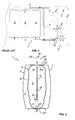
- the assembly 1 may comprise a tubular member 13 made of a rigid, semirigid or flexible material, extending at least partly within the inner container 4, in fluid communication with the interface 3, e.g. as shown in FIG. 2
- the tubular member 13 may have a side wall 14 with a number of holes 15 for filtering the used working liquid to be collected in the inner container 4.
- any coarse solid particles of dirt collected during washing and/or decontamination of the object O may be retained, to prevent them from contacting the wall 6 and damaging it.
- the tubular member 13 may have an end 16 which is adapted to be removably connected to a spent liquid discharging hole 17.
- the assembly of the invention may have a support structure 18 for the inner container 4 and/or the outer container 5. It will be understood that, if the outer container 5 is of the rigid type, as shown in FIG. 2. the support structure 18 will only engage the inner container 4, as the wall 7 needs no support.
- both the walls 7 and 6 are of the resilient and/or flexible type, like in the example of FIG. 3, both containers 4 and 5 shall be engaged by the support structure 18.
- the tubular member 13 may comprise removable connection means 19 of the bayonet, nut and screw, snap type or the like, to allow connection to the support structure 18, and removal thereof from the inner container 4 for cleaning. Thanks to this particular arrangement of the invention, any access by service personnel to the inner container 4 for inevitable cleaning and maintenance operations may be avoided.
- the removable connection means are two handles 20 and 20' which are removably attachable to appropriate locking receptacles 21 and 21'.
- the latter may have a pair of flanges 22 and 22' for connection to corresponding counterflanges 23 and 23' suitably provided on the outer container 5 and/or the inner container 4.
- the support structure 18 has an element for supporting, e.g. by means of an outer frame, the flanges 22 and 22' that support the walls 6 and 7.
- the removable connection means 19 may be located at least at one of the flanges 22 or 22' to minimize the overall size.
- FIG. 5 shows a further embodiment of a washing and decontamination unit of the invention, particularly suitable for urban solid waste containers W, which incorporates the container assembly as disclosed and claimed herein, and which may comprise a vehicle 24 for transport thereof on a roadway V.
- the unit of the invention will further include jet means 9, a first hydraulic circuit 10, a draining tank 11 and a second hydraulic circuit 12.
- the unit of the invention will have a minimized size, which is particularly suitable to the increasingly narrow and winding urban streets.
- the minimized size of the unit will further involve reduced investment and management costs, as well as a greatly reduced environmental impact.
- At least one the containers 4 or 5 is substantially of the variable volume type, as liquid decreases in one of the chambers 2 or 3 it increases in the other, the whole size being limited to the volume of the external container 5.
Landscapes
- Engineering & Computer Science (AREA)
- Mechanical Engineering (AREA)
- Cleaning By Liquid Or Steam (AREA)
- Detergent Compositions (AREA)
Applications Claiming Priority (1)
| Application Number | Priority Date | Filing Date | Title |
|---|---|---|---|
| ITVI20060010 ITVI20060010A1 (it) | 2006-01-11 | 2006-01-11 | Assieme contenitore per unita' di lavaggio e/o decontaminazione di oggetti, particolarmente cassonetti per la raccolta di rifiuti o similari |
Publications (1)
| Publication Number | Publication Date |
|---|---|
| EP1808386A1 true EP1808386A1 (de) | 2007-07-18 |
Family
ID=37837032
Family Applications (1)
| Application Number | Title | Priority Date | Filing Date |
|---|---|---|---|
| EP07000390A Withdrawn EP1808386A1 (de) | 2006-01-11 | 2007-01-10 | Behälteranordnung für eine Anlage zum Waschen und/oder zum Dekontaminieren von Gegenständen, insbesondere Müllbehälter oder dergleichen |
Country Status (2)
| Country | Link |
|---|---|
| EP (1) | EP1808386A1 (de) |
| IT (1) | ITVI20060010A1 (de) |
Citations (5)
| Publication number | Priority date | Publication date | Assignee | Title |
|---|---|---|---|---|
| DE2536774A1 (de) * | 1975-08-19 | 1977-03-03 | Haller Gmbh Fahrzeugbau | Muelltonnenwaschfahrzeug |
| DE3146533A1 (de) * | 1981-11-24 | 1983-06-01 | Jürgen 8990 Lindau Gutzeit | Fluessigkeitsbehaelter, insbesondere wasser- und abwasserbehaelter |
| DE8716514U1 (de) * | 1987-12-15 | 1988-03-10 | Hentschel, Joerg, 5000 Koeln, De | |
| WO1996019303A1 (en) * | 1994-12-20 | 1996-06-27 | Salvatore Ajena | Tank for fluids for use in urban cleansing vehicles |
| WO2003016096A1 (de) * | 2001-08-07 | 2003-02-27 | Manfred Feistmantl | Membrantank |
-
2006
- 2006-01-11 IT ITVI20060010 patent/ITVI20060010A1/it unknown
-
2007
- 2007-01-10 EP EP07000390A patent/EP1808386A1/de not_active Withdrawn
Patent Citations (5)
| Publication number | Priority date | Publication date | Assignee | Title |
|---|---|---|---|---|
| DE2536774A1 (de) * | 1975-08-19 | 1977-03-03 | Haller Gmbh Fahrzeugbau | Muelltonnenwaschfahrzeug |
| DE3146533A1 (de) * | 1981-11-24 | 1983-06-01 | Jürgen 8990 Lindau Gutzeit | Fluessigkeitsbehaelter, insbesondere wasser- und abwasserbehaelter |
| DE8716514U1 (de) * | 1987-12-15 | 1988-03-10 | Hentschel, Joerg, 5000 Koeln, De | |
| WO1996019303A1 (en) * | 1994-12-20 | 1996-06-27 | Salvatore Ajena | Tank for fluids for use in urban cleansing vehicles |
| WO2003016096A1 (de) * | 2001-08-07 | 2003-02-27 | Manfred Feistmantl | Membrantank |
Also Published As
| Publication number | Publication date |
|---|---|
| ITVI20060010A1 (it) | 2007-07-12 |
Similar Documents
| Publication | Publication Date | Title |
|---|---|---|
| JP4967022B2 (ja) | 清掃車の水再利用汚水処理装置 | |
| KR101156373B1 (ko) | 콘크리트 매립 장치 | |
| US8080111B1 (en) | Systems and methods for washing-out concrete pouring equipment | |
| WO2006044543A2 (en) | Compressed air vacuum cleaner | |
| WO1997001399A1 (en) | Washing objects and recovering contaminants | |
| JP2823095B2 (ja) | 吸込み圧力容器 | |
| MX2012013929A (es) | Sistema y metodo de remocion de residuos de grasa, aceite y sebo economicos. | |
| US8931495B1 (en) | Systems and methods utilizing baffle boxes for washing-out concrete pouring equipment | |
| EP1808386A1 (de) | Behälteranordnung für eine Anlage zum Waschen und/oder zum Dekontaminieren von Gegenständen, insbesondere Müllbehälter oder dergleichen | |
| AU2009202000B2 (en) | Systems and methods for washing-out concrete pouring equipment | |
| KR101080778B1 (ko) | 폐차의 액상류 분리 회수 장치 | |
| US5575908A (en) | Sewer system water purifier | |
| US4317720A (en) | Cleaning fluid recovery apparatus | |
| US20140291330A1 (en) | Dynamic bladder tank assembly for surface cleaning apparatus | |
| CN107030075A (zh) | 一种自动收集废渣的水污分离系统 | |
| US5976268A (en) | Method and apparatus for pressure washing | |
| DE2648851A1 (de) | Fahrzeug zum kanalreinigen und zum schlammtransport | |
| JP2021130958A (ja) | 管内清掃方法 | |
| JP4394258B2 (ja) | 可搬式オイルタンククリーナー | |
| CN111479636A (zh) | 用于清洁手推车的装置、系统及方法 | |
| CN212334884U (zh) | 一种污水过滤装置 | |
| CN215165165U (zh) | 一种利用再生水道路清扫除雪装置 | |
| US20110174335A1 (en) | Washing apparatus & system | |
| US20210101803A1 (en) | Portable fluid collection and filtration system | |
| CN219118348U (zh) | 一种清洗吸污车臭氧消杀装置 |
Legal Events
| Date | Code | Title | Description |
|---|---|---|---|
| PUAI | Public reference made under article 153(3) epc to a published international application that has entered the european phase |
Free format text: ORIGINAL CODE: 0009012 |
|
| AK | Designated contracting states |
Kind code of ref document: A1 Designated state(s): AT BE BG CH CY CZ DE DK EE ES FI FR GB GR HU IE IS IT LI LT LU LV MC NL PL PT RO SE SI SK TR |
|
| AX | Request for extension of the european patent |
Extension state: AL BA HR MK YU |
|
| AKX | Designation fees paid | ||
| REG | Reference to a national code |
Ref country code: DE Ref legal event code: 8566 |
|
| STAA | Information on the status of an ep patent application or granted ep patent |
Free format text: STATUS: THE APPLICATION IS DEEMED TO BE WITHDRAWN |
|
| 18D | Application deemed to be withdrawn |
Effective date: 20080119 |