EP1808338A1 - Power management system for in-vehicle apparatus and in-vehicle apparatus - Google Patents
Power management system for in-vehicle apparatus and in-vehicle apparatus Download PDFInfo
- Publication number
- EP1808338A1 EP1808338A1 EP07100397A EP07100397A EP1808338A1 EP 1808338 A1 EP1808338 A1 EP 1808338A1 EP 07100397 A EP07100397 A EP 07100397A EP 07100397 A EP07100397 A EP 07100397A EP 1808338 A1 EP1808338 A1 EP 1808338A1
- Authority
- EP
- European Patent Office
- Prior art keywords
- vehicle
- vehicle apparatus
- power
- power management
- communication
- Prior art date
- Legal status (The legal status is an assumption and is not a legal conclusion. Google has not performed a legal analysis and makes no representation as to the accuracy of the status listed.)
- Granted
Links
- 238000004891 communication Methods 0.000 claims abstract description 176
- 230000004044 response Effects 0.000 description 24
- 238000000034 method Methods 0.000 description 14
- 238000010586 diagram Methods 0.000 description 4
- 230000015654 memory Effects 0.000 description 4
- 238000001514 detection method Methods 0.000 description 3
- 102220076776 rs144141585 Human genes 0.000 description 3
- 102220008684 rs2017800 Human genes 0.000 description 3
- 239000000835 fiber Substances 0.000 description 2
- 102220009021 rs11549668 Human genes 0.000 description 2
- 102220008138 rs12252 Human genes 0.000 description 2
- 102220039210 rs149913848 Human genes 0.000 description 2
- 102220307951 rs1553603221 Human genes 0.000 description 2
- 102220014817 rs397517263 Human genes 0.000 description 2
- 102220008303 rs4904 Human genes 0.000 description 2
- 239000004065 semiconductor Substances 0.000 description 2
- 230000003936 working memory Effects 0.000 description 2
- 230000002159 abnormal effect Effects 0.000 description 1
- 230000005540 biological transmission Effects 0.000 description 1
- 125000004122 cyclic group Chemical group 0.000 description 1
- 238000003745 diagnosis Methods 0.000 description 1
- 230000003287 optical effect Effects 0.000 description 1
- 230000005236 sound signal Effects 0.000 description 1
Images





Classifications
-
- H—ELECTRICITY
- H04—ELECTRIC COMMUNICATION TECHNIQUE
- H04L—TRANSMISSION OF DIGITAL INFORMATION, e.g. TELEGRAPHIC COMMUNICATION
- H04L12/00—Data switching networks
- H04L12/02—Details
- H04L12/12—Arrangements for remote connection or disconnection of substations or of equipment thereof
-
- Y—GENERAL TAGGING OF NEW TECHNOLOGICAL DEVELOPMENTS; GENERAL TAGGING OF CROSS-SECTIONAL TECHNOLOGIES SPANNING OVER SEVERAL SECTIONS OF THE IPC; TECHNICAL SUBJECTS COVERED BY FORMER USPC CROSS-REFERENCE ART COLLECTIONS [XRACs] AND DIGESTS
- Y02—TECHNOLOGIES OR APPLICATIONS FOR MITIGATION OR ADAPTATION AGAINST CLIMATE CHANGE
- Y02D—CLIMATE CHANGE MITIGATION TECHNOLOGIES IN INFORMATION AND COMMUNICATION TECHNOLOGIES [ICT], I.E. INFORMATION AND COMMUNICATION TECHNOLOGIES AIMING AT THE REDUCTION OF THEIR OWN ENERGY USE
- Y02D30/00—Reducing energy consumption in communication networks
- Y02D30/50—Reducing energy consumption in communication networks in wire-line communication networks, e.g. low power modes or reduced link rate
Definitions
- the present invention relates to a power management system for in-vehicle apparatuses for controlling the power supplied to the in-vehicle apparatuses, and the in-vehicle apparatuses.
- the power management system controls the power supplied to the in-vehicle apparatuses except in the case of an in-vehicle apparatus which does not send condition information that the in-vehicle apparatus is ready for turning off, so that the power management system may conserve the power of the vehicle's battery.
- a radio receiver for receiving AM broadcast and FM broadcast a TV receiver for receiving telecast signals and displaying an image
- an audio device for playing an MD and/or a CD and/or a navigation apparatus for providing driving guidance for the vehicle may be mounted on the vehicle as the in-vehicle apparatuses.
- the MOST (Media Oriented Systems Transport) system is an example of an in-vehicle network (for example, Japanese Unexamined Patent Application Publication No. 2005-277711 ).
- the MOST system has a cyclic network and various in-vehicle apparatuses such as a navigation apparatus, an audio device, a radio receiver, and an AV amplifier are connected to each other. For example, digital data output from the audio device is transferred to the AV amplifier through the network and the signal input by the AV amplifier is amplified and output to a speaker.
- the MOST system is a network protocol using fiber optics and the in-vehicle apparatuses described above are connected to each other therein, so that there are numerous benefits to a user.
- the use of the MOST system results in a reduction in the weight of a wire harness for connecting components to each other and reduction in noise, and the burden on the developer of the system may be also reduced.
- the user may have means for intensively controlling various devices.
- the communication system described above controls the power of the entire system collectively instead of turning on/off the power supplied to each of the in-vehicle apparatuses in the system.
- each in-vehicle apparatus and a power management unit for controlling the power of the system are connected to each other with an LAN or the MOST, and request data for turning on/off the power supplied to each of the in-vehicle apparatuses is transferred from the power management unit, so that all of the connected in-vehicle apparatuses may be turned on or off.
- the power management unit when a program reset repeatedly occurs in any one of the in-vehicle apparatuses due to some sort of program factor, the power management unit recognizes that a new in-vehicle apparatus is connected to the power management unit every time the program reset occurs. As a result, every time the power management system recognizes the new connection of an in-vehicle apparatus, the power management system continuously provides registration processing for such a newly connected in-vehicle apparatus.
- the power management unit needs to receive responses that the connected in-vehicle apparatuses are ready for turning off from the connected in-vehicle apparatuses and needs to send request data to turn the in-vehicle apparatuses off.
- the series of resets occurs as described above, the reset in-vehicle apparatus cannot send the response that the in-vehicle apparatus is ready for turning off.
- the power management unit cannot send request data to turn the in-vehicle apparatus off. As a result, the power of the entire system cannot be turned off.
- some sort of program factor or non-program factor for example, when a system reset occurs due to a hardware error when just accessing a software
- a power management system for controlling at least one in-vehicle apparatus, including at least one in-vehicle apparatus and a power management device for connecting to the at least one in-vehicle apparatus and managing the power on/off of the at least one in-vehicle apparatus, the at least one in-vehicle apparatus, comprising: a power condition transferring means for transferring condition information indicating that the at least one in-vehicle apparatus is ready for turning off to the power management device; and a communication setting means for setting the at least one in-vehicle apparatus not to communicate with the power management device, provided that the at least one in-vehicle apparatus does not send condition information indicating that the at least one in-vehicle apparatus is ready for turning off by the power condition transferring means; and the power management device, comprising: a power off determining means for determining whether the at least one in-vehicle apparatus except in the case where the at least one in-
- the communication setting device means sets the at least one in-vehicle apparatus not to respond to a communication from the power management device.
- the power management system for the in-vehicle apparatuses further comprising: a counting means for counting the number of program resets in the in-vehicle apparatuses; and a reset number determining means for determining whether a predetermined number of program resets occur during a predetermined time period on the basis of the counting means, wherein: the communication setting means sets the power management device not to communicate with the at least one in-vehicle apparatus, provided that it is determined that the predetermined number of program resets occurred within the predetermined time period.
- Various exemplary implementations of the principles described herein provide in-vehicle apparatuses mounted on a vehicle that can be turned off on the basis of a request from a power management device, comprising: a power condition transferring means for transferring information indicating that the in-vehicle apparatus is ready for turning off to the power management device; and a communication setting means for setting the power management device not to communicate with the in-vehicle apparatus, provided that the in-vehicle apparatus does not send information indicating that the in-vehicle apparatus is ready for turning off by the power condition transferring means.
- the communication setting means sets the in-vehicle apparatus not to respond to the communication provided by the power management device.
- the in-vehicle apparatus further comprising: a counting means for counting the number of program resets; and a reset number determining means for determining whether a predetermined number of resets occur during a predetermined time period on the basis of the counting means, wherein: the communication setting means sets the power management device not to communicate with the in-vehicle apparatuses, provided that it is determined that the predetermined number of resets occurred within the predetermined time period.
- a power management system of an in-vehicle apparatus sets the in-vehicle apparatus, which does not send condition information indicating that the in-vehicle apparatus is ready for turning off, not to communicate with the power management device, determines whether in-vehicle apparatuses except the in-vehicle apparatus which is set not to communicate with the power management device are ready for turning off, and turns such in-vehicle apparatuses off after determining that such in-vehicle apparatuses are ready for turning off.
- the power management system ignores the existence of such in-vehicle apparatus, so that the power of the entire system may be turned off. As a result, the power-on state of the in-vehicle apparatuses may not continue after the vehicle engine stops and it may conserve the power of the vehicle's battery.
- the power control system of the in-vehicle apparatuses determines whether in-vehicle apparatuses except an in-vehicle apparatus, which is set not to respond to the communication provided by the power management device, are ready for turning off and turns the in-vehicle apparatuses off after determining that the in-vehicle apparatuses are ready for turning off.
- the power management system ignores the existence of such in-vehicle apparatus, so that the power of the entire system may be turned off. As a result, the power-on state of the in-vehicle apparatuses may not continue after the vehicle engine stops and it may conserve the power of the vehicle's battery.
- the power control system of in-vehicle apparatuses turns the in-vehicle apparatuses off when it is determined that in-vehicle apparatuses except an in-vehicle apparatus which is reset a predetermined number of times within a predetermined time period are ready for turning off. Therefore, even if a series of program resets occurs by some sort of program factor or non-program factor (for example, when a system reset occurs due to a hardware error when just accessing a software) and there is an in-vehicle apparatus which does not send condition information indicating that the in-vehicle apparatus is ready for turning off to the power management device, the power management system ignores the existence of such in-vehicle apparatus, so that the power of the entire system may be turned off. As a result, the power-on state of the in-vehicle apparatuses may not continue after the vehicle engine stops and it may conserve the power of the vehicle's battery.
- the in-vehicle apparatus When the in-vehicle apparatus does not send condition information indicating that the in-vehicle apparatus is ready for turning off, the in-vehicle apparatus sets the power management device not to communicate. Therefore, even if a series of program resets occurs by some sort of program factor or non-program factor (for example, when a system reset occurs due to a hardware error when just accessing a software) and there is an in-vehicle apparatus which does not send condition information indicating that the in-vehicle apparatus is ready for turning off to the power management device, the power management system ignores the existence of such in-vehicle apparatus, so that the power of the entire system including other in-vehicle apparatuses may be turned off. As a result, the power-on state of the in-vehicle apparatuses may not continue after the vehicle engine stops and it may conserve the power of the vehicle's battery.
- the in-vehicle apparatus When the in-vehicle apparatus does not send condition information indicating that the in-vehicle apparatus is ready for turning off, the in-vehicle apparatus sets the power management device not to communicate. Therefore, even if a series of program resets occurs by some sort of program factor or non-program factor (for example, when a system reset occurs due to a hardware error when just accessing a software) and there is an in-vehicle apparatus which does not send condition information indicating that the in-vehicle apparatus is ready for turning off to the power management device, the power management system ignores the existence of such in-vehicle apparatus, so that the power of the entire system including other in-vehicle apparatuses may be turned off. As a result, the power-on state of the in-vehicle apparatuses may not continue after the vehicle engine stops and it may conserve the power of the vehicle's battery.
- the in-vehicle apparatus When the in-vehicle apparatus resets a predetermined number of times within a predetermined time period, the in-vehicle apparatus sets the power management device not to communicate. Therefore, even if a series of program resets occurs by some sort of program factor or non-program factor (for example, when a system reset occurs due to a hardware error when just accessing a software) and there is an in-vehicle apparatus which does not send condition information indicating that the in-vehicle apparatus is ready for turning off to the power management device, the power management system ignores the existence of such in-vehicle apparatus, so that the power of the entire system including other in-vehicle apparatuses may be turned off. As a result, the power-on state of the in-vehicle apparatuses may not continue after the vehicle engine stops and it may conserve the power of the vehicle's battery.
- FIG. 1 is a structure outline of a power control system according to the first embodiment of the invention.
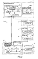
- FIG. 2 is a block diagram showing control structures of an in-vehicle apparatus and a communication master device in the power control system according to the first embodiment of the invention.
- FIG. 3 is a flowchart showing a series of reset processing program executed by the in-vehicle apparatus according to the first embodiment of the invention.
- FIG. 4 is a flowchart showing a power management processing program executed by the communication master device and the in-vehicle apparatuses according to the first embodiment of the invention.
- FIGs. 5A and 5B are diagrams showing recognition processing for the in-vehicle apparatus connected to the communication master device.
- FIG. 6 is a flowchart showing a power management processing program executed by the communication master device and the in-vehicle apparatus according to the second embodiment of the invention.
- a first embodiment and a second embodiment of the present invention according to a power management system and an in-vehicle apparatus are described with reference to the figures below.
- FIG. 1 is a diagram showing a structure outline of the power control system 1 according to the first embodiment.
- the power control system 1 has an in-vehicle network including a navigation apparatus 2, a CD player 3, a radio tuner 4, and an AV amplifier 5 as in-vehicle apparatuses mounted in a vehicle, and a communication master device (power management device) 6 for communicating and controlling each of the in-vehicle apparatuses 2 - 5, a communication network 7 for circularly connecting each of the in-vehicle apparatuses 2 - 5 and the communication master device 6.
- a communication master device power management device
- the communication network 7 is a data communication network including, for example, the MOST system.
- the communication master device 6 includes a monitor device 9 for displaying images and a controller 10 which has a plurality of buttons operated by a user.
- the navigation apparatus 2 is an in-vehicle apparatus for providing route guidance to a destination set by the user and a GPS 11 is connected to the navigation apparatus 2.
- the GPS 11 receives position information according to a current vehicle position.
- the navigation apparatus 2 reads out map information for the area surrounding the current vehicle position from map information storage means such as an internal CD, a DVD, or a hard disk drive on the basis of the received position information and transfers image data (map data) to the monitor device 9 through a transmission line on the basis of the read out information, so that the map and the current vehicle position are displayed on the monitor device 9.
- the navigation apparatus 2 transfers audio data of the route guidance to the AV amplifier 5 through the communication network 7.
- the AV amplifier 5 amplifies the input signal and a speaker 13 outputs an audio guidance.
- the CD player 3 is an audio device for playing a CD.
- the CD player 3 reads out digital data from the CD and transfers the digital data to the AV amplifier 5 through the communication network 7.
- the AV amplifier 5 amplifies the input signal and the speaker 13 outputs an audio message or music.
- the radio tuner 4 is a receiver for receiving radio broadcasting.
- the radio tuner 4 transfers a signal of an AM/FM broadcast received by an antenna 14 to the AV amplifier 5 through the communication network 7.
- the AV amplifier 5 amplifies the input signal and the speaker 13 outputs an audio message or music.
- the AV amplifier 5 is an amplifier for amplifying an input audio signal and the speaker 13 is connected to the AV amplifier 5.
- the AV amplifier 5 amplifies digital data input from the navigation apparatus 2, the CD player 3, and/or the radio tuner 4 and outputs the digital data from the speaker 13.
- the communication master device 6 is a control device for communicating with each of the in-vehicle apparatuses 2 - 5 via the communication network 7 and controlling the in-vehicle apparatuses 2 - 5.
- the monitor device 9 and/or the controller 10 are connected to the communication master device 6.
- the communication master device 6 requests each in-vehicle apparatus such as the navigation apparatus 2 or the CD player 3 to start various programs on the basis of the operation by the user.
- the communication master device 6 stores image data in an internal storage device and displays various types of image corresponding to the running in-vehicle apparatuses (except the navigation apparatus 2) on the monitor device 9.
- the communication master device 6 controls the power-on/off state of the in-vehicle apparatuses 2 - 5. More specifically, a key switch 15 is connected to the communication master device 6 for turning on/off a vehicle ignition or an ACC (accessory). When the ACC is on, the communication master device 6 transfers a data signal over the communication network 7 and requests the in-vehicle apparatuses 2 - 5 to turn on.
- the communication master device 6 stops transferring the data signal over the communication network 7 and requests the in-vehicle apparatuses 2 - 5 to turn off.
- a gateway ECU as an interface for receiving a vehicle signal or a diagnosis such as a CAN may be connected to the communication network 7 and the key switch 15 may be connected to the gateway ECU.
- FIG. 2 is a diagram showing the control structures of the in-vehicle apparatuses 2 - 5 and the communication master device 6 in the power control system 1 according to the first embodiment.
- the navigation apparatus 2 basically includes a navigation ECU (electronic control unit) 21 and a current position detection section 22.
- the navigation ECU (power condition transfer means, communication setting means, counting means, reset number determining means) 21 includes a CPU 31 as a calculating device and a control device for controlling the entire navigation apparatus 2 and an internal storage device such as an RAM 32, an ROM 33, and/or a flash memory 34.
- the RAM 32 is used as a working memory when the CPU 31 executes various calculations, and in the RAM 32, route data for a searched route, information regarding a starting time of a series of program resets caused by a program factor or a non-program factor, and a reset counter 35 for counting the number of resets may be stored.
- ROM 33 a control program, a series of reset processing programs (FIG.
- a power management control program for controlling the power-on/off state of the in-vehicle apparatuses on the basis of the communication provided by the communication master device 6 may be stored.
- a program read out from the ROM 33 may be stored.
- a semiconductor memory or a magnetic core may be used as the RAM 32, the ROM 33, or the flash memory 34.
- an MPU may be used as the calculating device and the control device instead of the CPU 31.
- the navigation ECU 21 controls the navigation apparatus 2 to turn on (FIG. 4). Meanwhile, when the communication master device 6 stops transferring the data signal (more specifically, when it is ordered that the navigation apparatus 2 is turned off), the navigation ECU 21 controls the navigation apparatus 2 to turn off.
- the navigation ECU 21 sets the in-vehicle apparatus not to respond to the communication provided by the communication master device 6 and controls the navigation apparatus 2 to turn off (FIG. 3).
- a current position detection section 22 includes the GPS 11 for detecting a current vehicle position and a current time by receiving an electric wave provided by a satellite and a map DB 24 for storing map data, so that it may be possible to specify the current vehicle position and the travel direction of the vehicle on the map.
- the communication master device 6 may basically include a communication master ECU 40 and various types of additional device such as the monitor device 9, the controller 10, or the key switch 15 connected to the communication master ECU 40.
- the communication master ECU (power-off detection means, power-off request means) 40 may include a CPU 41 as a calculating device and a control device for controlling the entire communication master device 6 and an internal storage device such as an RAM 42, and/or an ROM 43.
- the RAM 42 is used as a working memory when the CPU 41 executes various calculations, and in the RAM 42, IDs of in-vehicle apparatuses which respond to a connection acknowledgement request among the in-vehicle apparatuses 2 - 5 may be stored.
- ROM 43 a control program and a power management control program (FIG.
- a semiconductor memory or a magnetic core may be used as the RAM 42 or the ROM 43.
- an MPU may be used as the calculating device and the control device instead of the CPU 41.
- the communication master ECU 40 sends a connection acknowledgement request to each of the in-vehicle apparatuses 2 - 5 via the communication network 7 described later and stores the IDs of the in-vehicle apparatuses which respond to the connection acknowledgment request among the in-vehicle apparatuses 2 - 5, so that the communication master ECU 40 may recognize which in-vehicle apparatus is currently connected. Further, when ACC is on, the communication master ECU 40 starts sending data signals over the communication network 7 and requests each of the in-vehicle apparatuses 2 - 5 to turn on. When ACC is off, the communication master ECU 40 sends a power-off permission to each of the in-vehicle apparatuses 2 - 5 via the communication network 7.
- the communication master ECU 40 stops sending data signals over the communication network 7 and requests each of the in-vehicle apparatuses 2 - 5 to turn off (FIG. 4).
- the CD player 3 may basically include a CD player ECU 25.
- the radio tuner 4 may basically include a radio tuner ECU 26.
- the AV amplifier 5 may basically include an AV amplifier ECU 27. Note that although the details of the CD player ECU 25, the radio tuner ECU 26, and the AV amplifier ECU 27 are not described here, each of the ECUs may includes a CPU and an internal storage device such as an RAM, an ROM, and/or a flash memory as in the case of the navigation ECU 21.
- a storage range for storing a starting time of a series of program resets due to, for example, a program factor and a reset counter for counting the number of resets may be included as in the case of the navigation apparatus.
- a series of reset processing programs (FIG. 3) and a power management control program (FIG. 4) described later may be stored as in the case of the navigation apparatus.
- FIG. 3 is a flowchart showing the series of reset processing program executed by the in-vehicle apparatuses 2 - 5 according to the first embodiment.
- the series of reset processing program is a program for setting the in-vehicle apparatuses not to respond to the communication provided by the communication master device 6 and for turning the in-vehicle apparatuses off when the series of program reset occurs due to a program factor or a non-program factor (for example, when a system reset occurs due to a hardware error when just accessing a software).
- the program shown in the flowchart of FIG. 3 is stored in the ROMs and/or the RAMs of the ECUs 21 and 25 - 27 and executed by the CPUs after the in-vehicle apparatuses corresponding to the CPUs are turned on.
- the CPU determines whether the program is properly terminated without resetting in Step 1 (hereinafter referred to as S1). More specifically, when an ACC off sequence run flag is set on a procedure in S10 described later and when the power is properly turned off, it is determined that the program is properly terminated.
- the CPU stores a current time T obtained by an RTC (Real Time Clock) in the RAM.
- RTC Real Time Clock
- the current time T stored in the RAM in S3 is used in S15 as a starting time of a series of resets while it is determined whether a condition for turning off is met or not.
- S4 a communication control processing for responding to a connection acknowledgment request provided by the communication master device 6 or for receiving a request to start various types of control program is executed.
- the CPU executes standard control processing for in-vehicle apparatuses corresponding to communication control processing in S4. More specifically, for example, the navigation apparatus 2 executes a destination setting processing, a route search processing, and/or a guidance processing along the route on the basis of the instruction from the communication master device 6.
- the CD player 3 plays a CD, pauses the CD, and/or fast-forwards the CD on the basis of the instruction from the communication master device 6.
- the CPU determines whether the program is reset due to a program factor or a non-program factor (for example, when a system reset occurs due to a hardware error when just accessing a software).
- S9 it is determined whether data signal transfer on the communication network 7 is terminated, that is, whether the communication master device 6 requests for turning the in-vehicle apparatus off.
- the ACC off sequence run flag is set on the basis of the completion of the program.
- the CPU turns off the in-vehicle apparatus.
- the power-off condition here means a condition to determine whether a response to the power-off permission can be sent to the communication master device 6. More specifically, the condition in the first embodiment is that the series of program resets occurs a predetermined number of times (equal to or more than 11 times in the first embodiment) within a predetermined time period (60 seconds in the first embodiment).
- the processing in S16 is operated by communication setting means.
- the CPU stores the current time T obtained by the RTC to re-count the number of the series of resets (S18).
- the CPU initializes the count of the reset counter (CT) in the RAM and set the count as "1" (S19). Then the procedure goes to S4.
- the current time T stored in the RAM in S18 is used as a starting time of the series of resets while it is determined whether the power-off condition is met in S15.
- the processing in S2, S13, and S19 is operated by counting means.
- FIG. 4 is a flowchart showing a power management processing program executed by the communication master device 6 and the in-vehicle apparatuses 2 - 5 according to the first embodiment.
- the power management control program here is a program for managing the powers of the in-vehicle apparatuses by communicating with each of the in-vehicle apparatuses connected to the communication network 7. Note that, the program in the flowchart of FIG. 4 is stored in the ROM and/or the RAM of each of the ECUs 21, 25 - 27, and 40, and the program is repeatedly executed by the CPUs in certain intervals.
- the power management processing program executed by the CPU 41 of the communication master device 6 is described with reference to FIG. 4.
- the CPU 41 receives responses to the sent connection acknowledgment request in S23 from the in-vehicle apparatuses.
- IDs of in-vehicle apparatuses which responded to the connection acknowledgment request among all of the in-vehicle apparatuses are stored in the RAM 42. Therefore, it may be specified which in-vehicle apparatus is currently connected to the communication master device 6. Then the CPU 41 executes system communication processing such as a request for starting a control program for each of the connected in-vehicle apparatuses in S26.
- the ECUs 21 and 25 - 27 of the in-vehicle apparatuses are set not to respond to the communication provided by the communication master device 6 when the series of program resets occurs a predetermined number of times (equal to or more than 11 times in the first embodiment) within a predetermined time period (60 seconds in the first embodiment) (S16 in FIG. 3).
- the in-vehicle apparatuses which are set not to respond to the communication provided by the communication master device 6 do not respond to the connection acknowledgement request, so that the CPU 41 does not recognize such in-vehicle apparatuses as the in-vehicle apparatuses connected to the communication master device 6 (that is, the CPU 41 assumes that such in-vehicle apparatuses do not exist).
- the recognition processing of the in-vehicle apparatuses which are connected to the communication master device 6 is concretely described with reference to FIG. 5.
- the IDs of the in-vehicle apparatuses 2 - 5 are stored in the RAM 42 as shown in S25 in (A).
- the CPU 41 recognizes that the navigation apparatus 2, the CD player 3, the radio tuner 4, and the AV amplifier 5 are connected to the communication master device 6.
- the navigation apparatus 2 is repeatedly reset and is set not to respond to the communication provided by the communication master device 6 (S16 in FIG. 3), the navigation apparatus 2 does not respond to the connection acknowledgement request since then.
- the IDs of the CD player 3, the radio tuner 4, and the AV amplifier 5 other than the navigation apparatus 2 are stored in the RAM 42 as shown in (B).
- the CPU 41 recognizes that only the CD player 3, the radio tuner 4, and the AV amplifier 5 are connected to the communication master device 6.
- the CPU 41 sends the power-off permission to each of the in-vehicle apparatuses connected through the communication network 7 (the navigation apparatus 2, the CD player 3, the radio tuner 4, and the AV amplifier 5 in the first embodiment) for determining whether the in-vehicle apparatuses are ready for turning off (S29).
- the CPU 41 receives responses to the power-off permission in S29 sent from each of the in-vehicle apparatuses.
- S31 it is determined whether all expected responses to the power-off permission are received from all in-vehicle apparatuses which responded to the connection acknowledgement request in S25. For example, when the IDs of the CD player 3, the radio tuner 4, and the AV amplifier 5 other than the navigation apparatus 2 are stored in the RAM 42, the CPU 41 determines whether the responses to the power-off permission from the CD player 3, the radio tuner 4, and the AV amplifier 5 are received. Note that, the processing in S31 is operated by power-off determining means.
- the CPU 41 waits until receiving all responses to the power-off permission.
- the CPU 41 stops transferring the data signal over the communication network 7 to turn the in-vehicle apparatuses off (S32). As a result, the in-vehicle apparatuses connected to the communication network 7 are turned off. Note that, the processing in S32 is operated by power-off request means.
- the power management processing program executed by the CPUs of the in-vehicle apparatuses 2 - 5 connected to the communication master device 6 is described with reference to FIG. 4.
- the CPU determines whether the data signal sent from the communication master device 6 is received.
- Another control processing is executed for the in-vehicle apparatus in S43. More specifically, for example, according to the navigation apparatus 2, a destination setting processing, a route search processing, and/or a route guidance processing along the set route are executed on the basis of the request from the communication master device 6. According to the CD player 3, a CD playing processing, a pausing processing, and/or a fast-forwarding processing are executed on the basis of the request from the communication master device 6.
- connection acknowledgement request sent from the communication master device 6 is received.
- response to the connection acknowledgement request is sent to the communication master device 6, so that the communication master device 6 may specify which in-vehicle apparatus is currently connected to the communication master device 6.
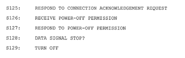
- the power-off permission sent from the communication master device 6 is received.
- the response to the power-off permission is sent to the communication master device 6, so that the communication master device 6 may determine whether the currently connected in-vehicle apparatus is ready for turning off. Note that, the processing in S47 is operated by power condition transferring means.
- the power management system ignores the existence of such in-vehicle apparatus, so that the power of the entire system may be turned off. As a result, the power-on state of the in-vehicle apparatuses may not continue after the vehicle engine stops and it may conserve the power of the vehicle's battery.
- FIG. 6 a power control system for an in-vehicle apparatus in the second embodiment is described with reference to FIG. 6. Note that, the same reference numerals as the power control system 1 in the first embodiment in FIGs. 1 - 5 are applied for identical parts or corresponding parts of the power control system in the second embodiment.
- the power control system 1 in the first embodiment regularly initializes IDs of in-vehicle apparatuses stored in the RAM 42 of the communication master device 6 regardless of whether or not abnormal communication occurs and re-recognizes which in-vehicle apparatus is connected to the communication master device 6 (S28).
- the power control system in the second embodiment initializes IDs of in-vehicle apparatuses stored in the RAM 42 of the communication master device 6 only when it is determined that a new in-vehicle apparatus is connected and re-recognizes which in-vehicle apparatus is connected to the communication master device 6.
- FIG. 6 is a flowchart showing the power management processing program executed by the communication master device 6 and the in-vehicle apparatuses 2 - 5 according to the second embodiment. Note that, the program in the flowchart of FIG. 6 is stored in the ROM and/or the RAM of the ECUs 21, 25 - 27, and 40 and is repeatedly executed by the CPUs in certain intervals.
- the power management processing program executed by the CPU 41 of the communication master device 6 is described with reference to FIG. 6.
- the CPU 41 receives responses to the request in S103 sent from the in-vehicle apparatuses.
- the IDs of the in-vehicle apparatuses which responded to the request among all of the in-vehicle apparatuses are stored in the RAM 42, so that it may be specified which in-vehicle apparatus is currently connected to the communication master device 6.
- the CPU 41 determines whether any in-vehicle apparatus which is newly connected to the communication network 7 is detected.
- the program reset occurs according to the in-vehicle apparatus connected to the communication network 7
- the response to the connection acknowledgement request is sent to the communication master device 6 again to inform the connection of the in-vehicle apparatus. Therefore, when the program of any one of the in-vehicle apparatuses 2 - 5 connected to the communication master device 6 is reset, the communication master device 6 detects the new connection of the in-vehicle apparatus.
- the power-off permission is sent to each of the in-vehicle apparatuses (the navigation apparatus 2, the CD player 3, the radio tuner 4, and the AV amplifier 5 in the second embodiment) connected through the communication network 7 for determining whether such in-vehicle apparatuses are ready for turning off (S110).
- the CPU 41 receives the responses to the power-off permission in S110 sent from each of the in-vehicle apparatuses.
- the CPU 41 waits until all expected responses are received.
- processing described in S121 - S129 executed by the CPUs of the in-vehicle apparatuses 2 - 5 connected to the communication master device 6 according to the power management processing program is same as the processing described in S41 - S49 executed by the CPUs of the in-vehicle apparatuses 2 - 5 according to the power management processing program of the power management system 1 according to the first embodiment (FIG. 4), so that a duplicated detail description thereof is not given herein.
- the in-vehicle apparatus when it is determined that any one of the in-vehicle apparatuses (the navigation apparatus 2, the CD player 3, the radio tuner 4, or the AV amplifier 5) connected to the communication master device 6 is repeatedly reset and that the program of the in-vehicle apparatus is reset a predetermined number of times (equal to or more than 11 times in the second embodiment) within a predetermined time period (60 seconds in the second embodiment), the in-vehicle apparatus is set not to respond to the communication provided by the communication master device 6.
- the power management system ignores the existence of such in-vehicle apparatus, so that the power of the entire system may be turned off. As a result, the power-on state of the in-vehicle apparatuses may not continue after the vehicle engine stops and it may conserve the power of the vehicle's battery.
- the navigation apparatus 2 the CD player 3, the radio tuner 4, and the AV amplifier 5 are described as the in-vehicle apparatuses mounted in the vehicle.
- in-vehicle apparatuses used in the power control system 1 are not limited to the particular apparatuses described above.
- an MD player, a DVD player, or an ETC device may be used.
- the power-off condition not to respond to the communication provided by the communication master device 6 is when the in-vehicle apparatus is reset a predetermined number of times within a predetermined time period.
- another condition may be applied. For example, the condition is only that the program is reset a predetermined number of times.
- the system in which the communication master device 6 and the in-vehicle apparatuses 2 - 5 are connected to each other through the MOST is described as an example of the power control system for in-vehicle apparatuses.
- any system in which the communication master device 6 and the in-vehicle apparatuses 2 - 5 are connected to each other may be used.
- a system in which the communication master device 6 and the in-vehicle apparatuses 2 - 5 are connected to each other through the LAN may be used.
- a communication method an optical communication with the fiber, an electric communication with an electric signal, or a radio communication may be used.
- any of in-vehicle apparatuses (a navigation apparatus, a CD player, a radio tuner, and an AV amplifier) connected to a communication master device is repeatedly reset and the program of the in-vehicle apparatus is reset a predetermined number of times (equal to or more than 11 times in a second embodiment) within a predetermined time period (60 seconds in a first embodiment), the in-vehicle apparatus is set not to respond to a communication provided by the communication master device.
Landscapes
- Engineering & Computer Science (AREA)
- Computer Networks & Wireless Communication (AREA)
- Signal Processing (AREA)
- Navigation (AREA)
- Fittings On The Vehicle Exterior For Carrying Loads, And Devices For Holding Or Mounting Articles (AREA)
- Power Sources (AREA)
- Circuits Of Receivers In General (AREA)
- Control Of Eletrric Generators (AREA)
- Auxiliary Drives, Propulsion Controls, And Safety Devices (AREA)
- Control Of Throttle Valves Provided In The Intake System Or In The Exhaust System (AREA)
Abstract
Description
- The present invention relates to a power management system for in-vehicle apparatuses for controlling the power supplied to the in-vehicle apparatuses, and the in-vehicle apparatuses. In particular, the power management system controls the power supplied to the in-vehicle apparatuses except in the case of an in-vehicle apparatus which does not send condition information that the in-vehicle apparatus is ready for turning off, so that the power management system may conserve the power of the vehicle's battery.
- Hitherto, various types of in-vehicle apparatus have been mounted on vehicles to make drivers and fellow passengers in the vehicle more comfortable. For example, a radio receiver for receiving AM broadcast and FM broadcast, a TV receiver for receiving telecast signals and displaying an image, an audio device for playing an MD and/or a CD, and/or a navigation apparatus for providing driving guidance for the vehicle may be mounted on the vehicle as the in-vehicle apparatuses.
- To transfer digital data such as digitized image data, audio data, or computer data among the various types of in-vehicle apparatus described above, large-capacity and high-speed communication is required. Therefore, the introduction of an in-vehicle network to transfer digital data even in a small space such as in a vehicle is under way in earnest. For example, the MOST (Media Oriented Systems Transport) system is an example of an in-vehicle network (for example,
Japanese Unexamined Patent Application Publication No. 2005-277711 - Further, the MOST system is a network protocol using fiber optics and the in-vehicle apparatuses described above are connected to each other therein, so that there are numerous benefits to a user. For example, the use of the MOST system results in a reduction in the weight of a wire harness for connecting components to each other and reduction in noise, and the burden on the developer of the system may be also reduced. As a result, the user may have means for intensively controlling various devices.
- For example, the communication system described above controls the power of the entire system collectively instead of turning on/off the power supplied to each of the in-vehicle apparatuses in the system. For example, each in-vehicle apparatus and a power management unit for controlling the power of the system are connected to each other with an LAN or the MOST, and request data for turning on/off the power supplied to each of the in-vehicle apparatuses is transferred from the power management unit, so that all of the connected in-vehicle apparatuses may be turned on or off.
- However, according to the power management system using the power management unit described above, when a program reset repeatedly occurs in any one of the in-vehicle apparatuses due to some sort of program factor, the power management unit recognizes that a new in-vehicle apparatus is connected to the power management unit every time the program reset occurs. As a result, every time the power management system recognizes the new connection of an in-vehicle apparatus, the power management system continuously provides registration processing for such a newly connected in-vehicle apparatus. Note that, before the power management unit turns each of the in-vehicle apparatuses off, the power management unit needs to receive responses that the connected in-vehicle apparatuses are ready for turning off from the connected in-vehicle apparatuses and needs to send request data to turn the in-vehicle apparatuses off. However, when the series of resets occurs as described above, the reset in-vehicle apparatus cannot send the response that the in-vehicle apparatus is ready for turning off. Further, because registration processing for the in-vehicle apparatus is repeatedly executed by the power management unit, the power management unit cannot send request data to turn the in-vehicle apparatus off. As a result, the power of the entire system cannot be turned off.
- Accordingly, it is an object for the present invention to provide a power management system for an in-vehicle apparatus and the in-vehicle apparatus for turning the power of the entire system off and preventing the battery of the vehicle from running out even when a series of program reset occurs by some sort of program factor or non-program factor (for example, when a system reset occurs due to a hardware error when just accessing a software) and there is an in-vehicle apparatus which does not send condition information indicating that the in-vehicle apparatus is ready for turning off to the power management device.
- To solve the problems described above, various exemplary implementations of the principles described herein provide a power management system for controlling at least one in-vehicle apparatus, including at least one in-vehicle apparatus and a power management device for connecting to the at least one in-vehicle apparatus and managing the power on/off of the at least one in-vehicle apparatus, the at least one in-vehicle apparatus, comprising: a power condition transferring means for transferring condition information indicating that the at least one in-vehicle apparatus is ready for turning off to the power management device; and a communication setting means for setting the at least one in-vehicle apparatus not to communicate with the power management device, provided that the at least one in-vehicle apparatus does not send condition information indicating that the at least one in-vehicle apparatus is ready for turning off by the power condition transferring means; and the power management device, comprising: a power off determining means for determining whether the at least one in-vehicle apparatus except in the case where the at least one in-vehicle apparatus is set not to communicate with the power management device, is ready for turning off when turning the at least one in-vehicle apparatus off; and a power-off request means for requesting the at least one in-vehicle apparatus to turn off, provided that the power-off determining device determines that the at least one in-vehicle apparatus is ready for turning off.
- Various exemplary implementations of the principles described herein provide the power management system for the at least one in-vehicle apparatus, wherein: the communication setting device means sets the at least one in-vehicle apparatus not to respond to a communication from the power management device.
- Various exemplary implementations of the principles described herein provide the power management system for the in-vehicle apparatuses, further comprising: a counting means for counting the number of program resets in the in-vehicle apparatuses; and a reset number determining means for determining whether a predetermined number of program resets occur during a predetermined time period on the basis of the counting means, wherein: the communication setting means sets the power management device not to communicate with the at least one in-vehicle apparatus, provided that it is determined that the predetermined number of program resets occurred within the predetermined time period.
- Various exemplary implementations of the principles described herein provide in-vehicle apparatuses mounted on a vehicle that can be turned off on the basis of a request from a power management device, comprising: a power condition transferring means for transferring information indicating that the in-vehicle apparatus is ready for turning off to the power management device; and a communication setting means for setting the power management device not to communicate with the in-vehicle apparatus, provided that the in-vehicle apparatus does not send information indicating that the in-vehicle apparatus is ready for turning off by the power condition transferring means.
- Various exemplary implementations of the principles described herein provide the in-vehicle apparatuses, wherein: the communication setting means sets the in-vehicle apparatus not to respond to the communication provided by the power management device.
- Various exemplary implementations of the principles described herein provide the in-vehicle apparatus, further comprising: a counting means for counting the number of program resets; and a reset number determining means for determining whether a predetermined number of resets occur during a predetermined time period on the basis of the counting means, wherein: the communication setting means sets the power management device not to communicate with the in-vehicle apparatuses, provided that it is determined that the predetermined number of resets occurred within the predetermined time period.
- A power management system of an in-vehicle apparatus sets the in-vehicle apparatus, which does not send condition information indicating that the in-vehicle apparatus is ready for turning off, not to communicate with the power management device, determines whether in-vehicle apparatuses except the in-vehicle apparatus which is set not to communicate with the power management device are ready for turning off, and turns such in-vehicle apparatuses off after determining that such in-vehicle apparatuses are ready for turning off. Therefore, even if a series of program resets occurs by some sort of program factor or non-program factor (for example, when a system reset occurs due to a hardware error when just accessing a software) and there is an in-vehicle apparatus which does not send condition information indicating that the in-vehicle apparatus is ready for turning off to the power management device, the power management system ignores the existence of such in-vehicle apparatus, so that the power of the entire system may be turned off. As a result, the power-on state of the in-vehicle apparatuses may not continue after the vehicle engine stops and it may conserve the power of the vehicle's battery.
- The power control system of the in-vehicle apparatuses determines whether in-vehicle apparatuses except an in-vehicle apparatus, which is set not to respond to the communication provided by the power management device, are ready for turning off and turns the in-vehicle apparatuses off after determining that the in-vehicle apparatuses are ready for turning off. Therefore, even if a series of program resets occurs by some sort of program factor or non-program factor (for example, when a system reset occurs due to a hardware error when just accessing a software) and there is an in-vehicle apparatus which does not send condition information indicating that the in-vehicle apparatus is ready for turning off to the power management device, the power management system ignores the existence of such in-vehicle apparatus, so that the power of the entire system may be turned off. As a result, the power-on state of the in-vehicle apparatuses may not continue after the vehicle engine stops and it may conserve the power of the vehicle's battery.
- The power control system of in-vehicle apparatuses turns the in-vehicle apparatuses off when it is determined that in-vehicle apparatuses except an in-vehicle apparatus which is reset a predetermined number of times within a predetermined time period are ready for turning off. Therefore, even if a series of program resets occurs by some sort of program factor or non-program factor (for example, when a system reset occurs due to a hardware error when just accessing a software) and there is an in-vehicle apparatus which does not send condition information indicating that the in-vehicle apparatus is ready for turning off to the power management device, the power management system ignores the existence of such in-vehicle apparatus, so that the power of the entire system may be turned off. As a result, the power-on state of the in-vehicle apparatuses may not continue after the vehicle engine stops and it may conserve the power of the vehicle's battery.
- When the in-vehicle apparatus does not send condition information indicating that the in-vehicle apparatus is ready for turning off, the in-vehicle apparatus sets the power management device not to communicate. Therefore, even if a series of program resets occurs by some sort of program factor or non-program factor (for example, when a system reset occurs due to a hardware error when just accessing a software) and there is an in-vehicle apparatus which does not send condition information indicating that the in-vehicle apparatus is ready for turning off to the power management device, the power management system ignores the existence of such in-vehicle apparatus, so that the power of the entire system including other in-vehicle apparatuses may be turned off. As a result, the power-on state of the in-vehicle apparatuses may not continue after the vehicle engine stops and it may conserve the power of the vehicle's battery.
- When the in-vehicle apparatus does not send condition information indicating that the in-vehicle apparatus is ready for turning off, the in-vehicle apparatus sets the power management device not to communicate. Therefore, even if a series of program resets occurs by some sort of program factor or non-program factor (for example, when a system reset occurs due to a hardware error when just accessing a software) and there is an in-vehicle apparatus which does not send condition information indicating that the in-vehicle apparatus is ready for turning off to the power management device, the power management system ignores the existence of such in-vehicle apparatus, so that the power of the entire system including other in-vehicle apparatuses may be turned off. As a result, the power-on state of the in-vehicle apparatuses may not continue after the vehicle engine stops and it may conserve the power of the vehicle's battery.
- When the in-vehicle apparatus resets a predetermined number of times within a predetermined time period, the in-vehicle apparatus sets the power management device not to communicate. Therefore, even if a series of program resets occurs by some sort of program factor or non-program factor (for example, when a system reset occurs due to a hardware error when just accessing a software) and there is an in-vehicle apparatus which does not send condition information indicating that the in-vehicle apparatus is ready for turning off to the power management device, the power management system ignores the existence of such in-vehicle apparatus, so that the power of the entire system including other in-vehicle apparatuses may be turned off. As a result, the power-on state of the in-vehicle apparatuses may not continue after the vehicle engine stops and it may conserve the power of the vehicle's battery.
- FIG. 1 is a structure outline of a power control system according to the first embodiment of the invention.
- FIG. 2 is a block diagram showing control structures of an in-vehicle apparatus and a communication master device in the power control system according to the first embodiment of the invention.
- FIG. 3 is a flowchart showing a series of reset processing program executed by the in-vehicle apparatus according to the first embodiment of the invention.
- FIG. 4 is a flowchart showing a power management processing program executed by the communication master device and the in-vehicle apparatuses according to the first embodiment of the invention.
- FIGs. 5A and 5B are diagrams showing recognition processing for the in-vehicle apparatus connected to the communication master device.
- FIG. 6 is a flowchart showing a power management processing program executed by the communication master device and the in-vehicle apparatus according to the second embodiment of the invention.
- A first embodiment and a second embodiment of the present invention according to a power management system and an in-vehicle apparatus are described with reference to the figures below.
- First, a structure outline of a
power control system 1 according to the first embodiment is described with reference to FIG. 1. FIG. 1 is a diagram showing a structure outline of thepower control system 1 according to the first embodiment. - As shown in FIG. 1, the
power control system 1 according to the first embodiment has an in-vehicle network including anavigation apparatus 2, aCD player 3, aradio tuner 4, and anAV amplifier 5 as in-vehicle apparatuses mounted in a vehicle, and a communication master device (power management device) 6 for communicating and controlling each of the in-vehicle apparatuses 2 - 5, a communication network 7 for circularly connecting each of the in-vehicle apparatuses 2 - 5 and thecommunication master device 6. - The communication network 7 is a data communication network including, for example, the MOST system. The
communication master device 6 includes amonitor device 9 for displaying images and acontroller 10 which has a plurality of buttons operated by a user. - The
navigation apparatus 2 is an in-vehicle apparatus for providing route guidance to a destination set by the user and aGPS 11 is connected to thenavigation apparatus 2. TheGPS 11 receives position information according to a current vehicle position. Thenavigation apparatus 2 reads out map information for the area surrounding the current vehicle position from map information storage means such as an internal CD, a DVD, or a hard disk drive on the basis of the received position information and transfers image data (map data) to themonitor device 9 through a transmission line on the basis of the read out information, so that the map and the current vehicle position are displayed on themonitor device 9. Thenavigation apparatus 2 transfers audio data of the route guidance to theAV amplifier 5 through the communication network 7. TheAV amplifier 5 amplifies the input signal and aspeaker 13 outputs an audio guidance. TheCD player 3 is an audio device for playing a CD. TheCD player 3 reads out digital data from the CD and transfers the digital data to theAV amplifier 5 through the communication network 7. TheAV amplifier 5 amplifies the input signal and thespeaker 13 outputs an audio message or music. Theradio tuner 4 is a receiver for receiving radio broadcasting. Theradio tuner 4 transfers a signal of an AM/FM broadcast received by anantenna 14 to theAV amplifier 5 through the communication network 7. TheAV amplifier 5 amplifies the input signal and thespeaker 13 outputs an audio message or music. TheAV amplifier 5 is an amplifier for amplifying an input audio signal and thespeaker 13 is connected to theAV amplifier 5. TheAV amplifier 5 amplifies digital data input from thenavigation apparatus 2, theCD player 3, and/or theradio tuner 4 and outputs the digital data from thespeaker 13. - The
communication master device 6 is a control device for communicating with each of the in-vehicle apparatuses 2 - 5 via the communication network 7 and controlling the in-vehicle apparatuses 2 - 5. Themonitor device 9 and/or thecontroller 10 are connected to thecommunication master device 6. When the user operates thecontroller 10, thecommunication master device 6 requests each in-vehicle apparatus such as thenavigation apparatus 2 or theCD player 3 to start various programs on the basis of the operation by the user. Thecommunication master device 6 stores image data in an internal storage device and displays various types of image corresponding to the running in-vehicle apparatuses (except the navigation apparatus 2) on themonitor device 9. (For example, a title of a song and/or the number of tracks are displayed while theCD player 3 is running, and a frequency and/or a name of a radio station are displayed while the radio tuner is running.) Thecommunication master device 6 according to the first embodiment controls the power-on/off state of the in-vehicle apparatuses 2 - 5. More specifically, akey switch 15 is connected to thecommunication master device 6 for turning on/off a vehicle ignition or an ACC (accessory). When the ACC is on, thecommunication master device 6 transfers a data signal over the communication network 7 and requests the in-vehicle apparatuses 2 - 5 to turn on. When the ACC is off, thecommunication master device 6 stops transferring the data signal over the communication network 7 and requests the in-vehicle apparatuses 2 - 5 to turn off. Note that a gateway ECU as an interface for receiving a vehicle signal or a diagnosis such as a CAN may be connected to the communication network 7 and thekey switch 15 may be connected to the gateway ECU. - Next, control structures of the in-vehicle apparatuses 2 - 5 and the
communication master device 6 in thepower control system 1 according to the first embodiment will be described with reference to FIG. 2. FIG. 2 is a diagram showing the control structures of the in-vehicle apparatuses 2 - 5 and thecommunication master device 6 in thepower control system 1 according to the first embodiment. - First, the control structure of the
navigation apparatus 2 will be described with reference to FIG. 2. Thenavigation apparatus 2 basically includes a navigation ECU (electronic control unit) 21 and a currentposition detection section 22. - The navigation ECU (power condition transfer means, communication setting means, counting means, reset number determining means) 21 includes a
CPU 31 as a calculating device and a control device for controlling theentire navigation apparatus 2 and an internal storage device such as anRAM 32, anROM 33, and/or aflash memory 34. TheRAM 32 is used as a working memory when theCPU 31 executes various calculations, and in theRAM 32, route data for a searched route, information regarding a starting time of a series of program resets caused by a program factor or a non-program factor, and areset counter 35 for counting the number of resets may be stored. In theROM 33, a control program, a series of reset processing programs (FIG. 3) for setting an in-vehicle apparatus not to respond to a communication from thecommunication master device 6 and for turning the in-vehicle apparatus off when the series of resets occurs, and a power management control program (FIG. 4) for controlling the power-on/off state of the in-vehicle apparatuses on the basis of the communication provided by thecommunication master device 6 may be stored. In theflash memory 34, a program read out from theROM 33 may be stored. Note that, a semiconductor memory or a magnetic core may be used as theRAM 32, theROM 33, or theflash memory 34. Further, an MPU may be used as the calculating device and the control device instead of theCPU 31. - When the
communication master device 6 sends a data signal through the communication network 7 (more specifically, when it is ordered that thenavigation apparatus 2 should be turned on), thenavigation ECU 21 controls thenavigation apparatus 2 to turn on (FIG. 4). Meanwhile, when thecommunication master device 6 stops transferring the data signal (more specifically, when it is ordered that thenavigation apparatus 2 is turned off), thenavigation ECU 21 controls thenavigation apparatus 2 to turn off. Further, when a series of program resets occurs a predetermined number of times (equal to or more than 11 times in the first embodiment) within a predetermined time period (60 seconds in the first embodiment) due to a program factor or a non-program factor (for example, when a system reset occurs due to a hardware error when just accessing a software), thenavigation ECU 21 sets the in-vehicle apparatus not to respond to the communication provided by thecommunication master device 6 and controls thenavigation apparatus 2 to turn off (FIG. 3). - A current
position detection section 22 includes theGPS 11 for detecting a current vehicle position and a current time by receiving an electric wave provided by a satellite and amap DB 24 for storing map data, so that it may be possible to specify the current vehicle position and the travel direction of the vehicle on the map. - Next, the control structure of the
communication master device 6 will be described with reference to FIG. 2. Thecommunication master device 6 may basically include acommunication master ECU 40 and various types of additional device such as themonitor device 9, thecontroller 10, or thekey switch 15 connected to thecommunication master ECU 40. - The communication master ECU (power-off detection means, power-off request means) 40 may include a
CPU 41 as a calculating device and a control device for controlling the entirecommunication master device 6 and an internal storage device such as anRAM 42, and/or anROM 43. TheRAM 42 is used as a working memory when theCPU 41 executes various calculations, and in theRAM 42, IDs of in-vehicle apparatuses which respond to a connection acknowledgement request among the in-vehicle apparatuses 2 - 5 may be stored. In theROM 43, a control program and a power management control program (FIG. 4) for controlling the power-on/off state of the in-vehicle apparatuses by communicating with each of the in-vehicle apparatuses connected to the communication network 7 may be stored.
Note that, a semiconductor memory or a magnetic core may be used as theRAM 42 or theROM 43. Further, an MPU may be used as the calculating device and the control device instead of theCPU 41. - The
communication master ECU 40 sends a connection acknowledgement request to each of the in-vehicle apparatuses 2 - 5 via the communication network 7 described later and stores the IDs of the in-vehicle apparatuses which respond to the connection acknowledgment request among the in-vehicle apparatuses 2 - 5, so that thecommunication master ECU 40 may recognize which in-vehicle apparatus is currently connected. Further, when ACC is on, thecommunication master ECU 40 starts sending data signals over the communication network 7 and requests each of the in-vehicle apparatuses 2 - 5 to turn on. When ACC is off, thecommunication master ECU 40 sends a power-off permission to each of the in-vehicle apparatuses 2 - 5 via the communication network 7. Then after all of the in-vehicle apparatuses which are currently connected to thecommunication master ECU 40 respond to the permission, thecommunication master ECU 40 stops sending data signals over the communication network 7 and requests each of the in-vehicle apparatuses 2 - 5 to turn off (FIG. 4). - The
CD player 3 may basically include aCD player ECU 25. Theradio tuner 4 may basically include aradio tuner ECU 26. TheAV amplifier 5 may basically include anAV amplifier ECU 27. Note that although the details of theCD player ECU 25, theradio tuner ECU 26, and theAV amplifier ECU 27 are not described here, each of the ECUs may includes a CPU and an internal storage device such as an RAM, an ROM, and/or a flash memory as in the case of thenavigation ECU 21. Further, in the RAMs of those in-vehicle apparatuses, a storage range for storing a starting time of a series of program resets due to, for example, a program factor and a reset counter for counting the number of resets may be included as in the case of the navigation apparatus. Further, in the ROM, a series of reset processing programs (FIG. 3) and a power management control program (FIG. 4) described later may be stored as in the case of the navigation apparatus. - Next, series of reset processing program executed by each of the
ECUs 21 and 25 - 27 of the in-vehicle apparatuses (thenavigation apparatus 2, theCD player 3, theradio tuner 4, and theAV amplifier 5 in the first embodiment) in thepower control system 1 having the structure described above according to the first embodiment will be described with reference to FIG. 3. FIG. 3 is a flowchart showing the series of reset processing program executed by the in-vehicle apparatuses 2 - 5 according to the first embodiment. The series of reset processing program is a program for setting the in-vehicle apparatuses not to respond to the communication provided by thecommunication master device 6 and for turning the in-vehicle apparatuses off when the series of program reset occurs due to a program factor or a non-program factor (for example, when a system reset occurs due to a hardware error when just accessing a software). Note that, the program shown in the flowchart of FIG. 3 is stored in the ROMs and/or the RAMs of theECUs 21 and 25 - 27 and executed by the CPUs after the in-vehicle apparatuses corresponding to the CPUs are turned on. - In the series of reset processing program, the CPU determines whether the program is properly terminated without resetting in Step 1 (hereinafter referred to as S1). More specifically, when an ACC off sequence run flag is set on a procedure in S10 described later and when the power is properly turned off, it is determined that the program is properly terminated.
- When it is determined that the program is properly terminated (S1=YES), the reset counter in the RAM is initialized and the counter value (CT) is set as "0" (S2).
- In S3, the CPU stores a current time T obtained by an RTC (Real Time Clock) in the RAM. Note that, the current time T stored in the RAM in S3 is used in S15 as a starting time of a series of resets while it is determined whether a condition for turning off is met or not. In S4, a communication control processing for responding to a connection acknowledgment request provided by the
communication master device 6 or for receiving a request to start various types of control program is executed. - In S5, the CPU executes standard control processing for in-vehicle apparatuses corresponding to communication control processing in S4. More specifically, for example, the
navigation apparatus 2 executes a destination setting processing, a route search processing, and/or a guidance processing along the route on the basis of the instruction from thecommunication master device 6. TheCD player 3 plays a CD, pauses the CD, and/or fast-forwards the CD on the basis of the instruction from thecommunication master device 6. - In S6, the CPU determines whether the program is reset due to a program factor or a non-program factor (for example, when a system reset occurs due to a hardware error when just accessing a software).
- When it is determined that the program is reset (S6=YES), the procedure returns to S1. When it is determined that the program is not reset (S6=NO), the procedure goes to S7.
- In S7, the CPU determines whether the power-off permission sent from the
communication master device 6 is received. When it is determined that the power-off permission is not received (S7=NO), the procedure returns to S4 and various control processing is again executed. When it is determined that the power-off permission is received (S7=YES), the CPU sends response to the power-off permission to thecommunication master device 6 and informs thecommunication master device 6 of being ready for turning off (S8). - In S9, it is determined whether data signal transfer on the communication network 7 is terminated, that is, whether the
communication master device 6 requests for turning the in-vehicle apparatus off. When it is determined that data signal transfer is not terminated (S9=NO), the procedure does not progress until the data signal transfer is terminated. When it is determined that data signal transfer is terminated (S9=YES), the procedure goes to S10. - In S10, the ACC off sequence run flag is set on the basis of the completion of the program. In S11, the CPU turns off the in-vehicle apparatus.
- When it is determined that the program is not successfully terminated in S1 (S1=NO), that is, it is determined that the program is reset and crashed, the current time t obtained by the RTC is stored in the RAM (S12). Note that, the current time t stored in the RAM in S12 is used as a starting time of last reset while it is determined whether the power-off condition is met in S15. In S13, "1" is added for the reset counter value (CT) in the RAM.
- In S14, it is determined whether the count of the reset counter (CT) in the RAM is 1, that is, whether the first program reset occurs after the program is terminated. When it is determined that the count of the reset counter (CT) in the RAM is 1 (S14=YES), the procedure returns to S3 to store the starting time T of the series of resets.
- When it is determined that the count of the reset counter (CT) in the RAM is other than 1 (S14=NO), it is further determined whether the power-off condition is met (S15). The power-off condition here means a condition to determine whether a response to the power-off permission can be sent to the
communication master device 6. More specifically, the condition in the first embodiment is that the series of program resets occurs a predetermined number of times (equal to or more than 11 times in the first embodiment) within a predetermined time period (60 seconds in the first embodiment). Then, when "t<T+60 sec" is true according to the starting time T of the series of resets stored in S3 or S18 and the starting time t of the last reset stored in S12, and when the count of the reset counter (CT) is greater than 10 (CT>10), it is determined that the power-off condition is met. - When it is determined that the power-off condition is met (S15=YES), the in-vehicle apparatus is set not to respond to the communication provided by the communication master device 6 (S16) and the procedures goes to S9. Note that, the in-vehicle apparatus set not to respond to the communication provided by the
communication master device 6 in S9 is not recognized by thecommunication master device 6 as an in-vehicle apparatus connected to the communication network 7 (S25 in FIG. 4), so that even if any one of the in-vehicle apparatuses is repeatedly reset, thecommunication master device 6 stops transferring a data signal and requests the entirepower control system 1 to turn off. The processing in S16 is operated by communication setting means. - When it is determined that the power-off condition is not met (S15=NO), it is further determined whether the count of the reset counter CT is greater than 10 (CT>10), that is, whether it takes equal to or more than 60 seconds for the in-vehicle apparatus to be repeatedly reset equal to or more than 11 times (S17). Note that, the processing in S17 is operated by reset number determining means.
- As a result, when it is determined that the count of the reset counter CT is greater than 10 (CT>10) (S17=YES), the CPU stores the current time T obtained by the RTC to re-count the number of the series of resets (S18). In S19, the CPU initializes the count of the reset counter (CT) in the RAM and set the count as "1" (S19). Then the procedure goes to S4. Note that, the current time T stored in the RAM in S18 is used as a starting time of the series of resets while it is determined whether the power-off condition is met in S15. The processing in S2, S13, and S19 is operated by counting means.
- When it is determined that the count of the reset counter (CT) is equal to or less than 10 (CT>10) (S17=NO), that is, that the number of the reset during the series of resets is less than 11 times since the number of times starts being counted, the procedures goes to S4 and the number of reset is ongoingly counted.
- Next, a power management control program executed by the
communication master ECU 40 of thecommunication master device 6 and theECUs 21 and 25 - 27 of the in-vehicle apparatuses (thenavigation apparatus 2, theCD player 3, theradio tuner 4, and theAV amplifier 5 in the first embodiment) in thepower control system 1 according to the first embodiment will be described with reference to FIG. 4. FIG. 4 is a flowchart showing a power management processing program executed by thecommunication master device 6 and the in-vehicle apparatuses 2 - 5 according to the first embodiment. The power management control program here is a program for managing the powers of the in-vehicle apparatuses by communicating with each of the in-vehicle apparatuses connected to the communication network 7. Note that, the program in the flowchart of FIG. 4 is stored in the ROM and/or the RAM of each of theECUs 21, 25 - 27, and 40, and the program is repeatedly executed by the CPUs in certain intervals. - First, the power management processing program executed by the
CPU 41 of thecommunication master device 6 is described with reference to FIG. 4. In S21, theCPU 41 determines whether thekey switch 15 is turned ACC on. When it is determined that the ACC is not on (S21=NO), the power management processing program is terminated. - When it is determined that the ACC is on (S21=YES), the
CPU 41 starts transferring a data signal over the communication network 7 for turning on the power of the in-vehicle apparatus in S22. In S23, theCPU 41 transfers a connection acknowledgement request to each of the in-vehicle apparatuses (thenavigation apparatus 2, theCD player 3, theradio tuner 4, and theAV amplifier 5 in the first embodiment) connected through the communication network 7. - In S24, the
CPU 41 receives responses to the sent connection acknowledgment request in S23 from the in-vehicle apparatuses. In S25, IDs of in-vehicle apparatuses which responded to the connection acknowledgment request among all of the in-vehicle apparatuses are stored in theRAM 42. Therefore, it may be specified which in-vehicle apparatus is currently connected to thecommunication master device 6. Then theCPU 41 executes system communication processing such as a request for starting a control program for each of the connected in-vehicle apparatuses in S26. - In S27, the
CPU 41 determines whether thekey switch 15 is turned ACC off. When it is determined that the ACC is not off (S27=NO), the IDs of the in-vehicle apparatuses stored in theRAM 42 in S25 are initialized (S28), and the procedure returns to S23. Then the connection acknowledgment request is again transferred and the IDs of only in-vehicle apparatuses which respond to the request are stored. - As described above, the
ECUs 21 and 25 - 27 of the in-vehicle apparatuses are set not to respond to the communication provided by thecommunication master device 6 when the series of program resets occurs a predetermined number of times (equal to or more than 11 times in the first embodiment) within a predetermined time period (60 seconds in the first embodiment) (S16 in FIG. 3). As a result, the in-vehicle apparatuses which are set not to respond to the communication provided by thecommunication master device 6 do not respond to the connection acknowledgement request, so that theCPU 41 does not recognize such in-vehicle apparatuses as the in-vehicle apparatuses connected to the communication master device 6 (that is, theCPU 41 assumes that such in-vehicle apparatuses do not exist). - The recognition processing of the in-vehicle apparatuses which are connected to the
communication master device 6 is concretely described with reference to FIG. 5. When thenavigation apparatus 2, theCD player 3, theradio tuner 4, and theAV amplifier 5 respond to the connection acknowledgment request, the IDs of the in-vehicle apparatuses 2 - 5 are stored in theRAM 42 as shown in S25 in (A). TheCPU 41 recognizes that thenavigation apparatus 2, theCD player 3, theradio tuner 4, and theAV amplifier 5 are connected to thecommunication master device 6. When thenavigation apparatus 2 is repeatedly reset and is set not to respond to the communication provided by the communication master device 6 (S16 in FIG. 3), thenavigation apparatus 2 does not respond to the connection acknowledgement request since then. As a result, in S25, the IDs of theCD player 3, theradio tuner 4, and theAV amplifier 5 other than thenavigation apparatus 2 are stored in theRAM 42 as shown in (B). TheCPU 41 recognizes that only theCD player 3, theradio tuner 4, and theAV amplifier 5 are connected to thecommunication master device 6. - When it is determined that the ACC is off in S27 (S27=YES), the
CPU 41 sends the power-off permission to each of the in-vehicle apparatuses connected through the communication network 7 (thenavigation apparatus 2, theCD player 3, theradio tuner 4, and theAV amplifier 5 in the first embodiment) for determining whether the in-vehicle apparatuses are ready for turning off (S29). - In S30, the
CPU 41 receives responses to the power-off permission in S29 sent from each of the in-vehicle apparatuses. In S31, it is determined whether all expected responses to the power-off permission are received from all in-vehicle apparatuses which responded to the connection acknowledgement request in S25. For example, when the IDs of theCD player 3, theradio tuner 4, and theAV amplifier 5 other than thenavigation apparatus 2 are stored in theRAM 42, theCPU 41 determines whether the responses to the power-off permission from theCD player 3, theradio tuner 4, and theAV amplifier 5 are received. Note that, the processing in S31 is operated by power-off determining means. - When it is determined that the responses to the power-off permission from all of the in-vehicle apparatuses which responded to the connection acknowledgement request are not received (S31=NO), the
CPU 41 waits until receiving all responses to the power-off permission. When it is determined that the all expected responses to the power-off permission from the in-vehicle apparatuses which responded to the connection acknowledgement request are received (S31=YES), theCPU 41 stops transferring the data signal over the communication network 7 to turn the in-vehicle apparatuses off (S32). As a result, the in-vehicle apparatuses connected to the communication network 7 are turned off. Note that, the processing in S32 is operated by power-off request means. - Next, the power management processing program executed by the CPUs of the in-vehicle apparatuses 2 - 5 connected to the
communication master device 6 is described with reference to FIG. 4. In S41, the CPU determines whether the data signal sent from thecommunication master device 6 is received. - When it is determined that the data signal is received (S41=YES), the in-vehicle apparatus is turned on (S42). When it is determined that the data signal is not received (S41=NO), the power management processing program is terminated.
- Another control processing is executed for the in-vehicle apparatus in S43. More specifically, for example, according to the
navigation apparatus 2, a destination setting processing, a route search processing, and/or a route guidance processing along the set route are executed on the basis of the request from thecommunication master device 6. According to theCD player 3, a CD playing processing, a pausing processing, and/or a fast-forwarding processing are executed on the basis of the request from thecommunication master device 6. - In S44, the connection acknowledgement request sent from the
communication master device 6 is received. In S45, the response to the connection acknowledgement request is sent to thecommunication master device 6, so that thecommunication master device 6 may specify which in-vehicle apparatus is currently connected to thecommunication master device 6. - In S46, the power-off permission sent from the
communication master device 6 is received. In S47, the response to the power-off permission is sent to thecommunication master device 6, so that thecommunication master device 6 may determine whether the currently connected in-vehicle apparatus is ready for turning off. Note that, the processing in S47 is operated by power condition transferring means. - In S48, the CPU determines whether the data signal is no more transferred from the
communication master device 6. When it is determined that the data signal is no more transferred (S48=YES), the corresponding in-vehicle apparatus is turned off (S49). When it is determined that the data signal is still transferred, (S48=NO), the CPU waits until the transfer of the data signal stops. - As described in detail above, according to the
power control system 1 in the first embodiment, when it is determined that any one of the in-vehicle apparatuses (thenavigation apparatus 2, theCD player 3, theradio tuner 4, and the AV amplifier 5) connected to thecommunication master device 6 is repeatedly reset and that the corresponding program is reset a predetermined number of times (equal to or more than 11 times in the first embodiment) within a predetermined time period (60 seconds in the first embodiment) (S15=YES), the in-vehicle apparatus is set not to respond to the communication provided by the communication master device 6 (S16). Meanwhile, when thecommunication master device 6 recognizes in-vehicle apparatuses which responded to the connection acknowledgement request as currently connected in-vehicle apparatuses (S25) and when it is determined that all expected responses to the power-off permission from all of the currently connected in-vehicle apparatuses are received (S31=YES), thecommunication master device 6 requests the in-vehicle apparatuses to turn off (S32). Therefore, even if a series of program resets occurs by some sort of program factor or non-program factor (for example, when a system reset occurs due to a hardware error when just accessing a software) and there is an in-vehicle apparatus which does not send condition information indicating that the in-vehicle apparatus is ready for turning off to the power management device, the power management system ignores the existence of such in-vehicle apparatus, so that the power of the entire system may be turned off. As a result, the power-on state of the in-vehicle apparatuses may not continue after the vehicle engine stops and it may conserve the power of the vehicle's battery. The second embodiment - Next, a power control system for an in-vehicle apparatus in the second embodiment is described with reference to FIG. 6. Note that, the same reference numerals as the
power control system 1 in the first embodiment in FIGs. 1 - 5 are applied for identical parts or corresponding parts of the power control system in the second embodiment. - There is not much difference between the structure outline of the power control system in the second embodiment and the structure outline of the
power control system 1 in the first embodiment. Further, there is not much difference between various types of control processing in the second embodiment and the control processing of thepower control system 1 in the first embodiment. - However, there is one difference between the
power control system 1 in the first embodiment and the power control system in the second embodiment. Thepower control system 1 in the first embodiment regularly initializes IDs of in-vehicle apparatuses stored in theRAM 42 of thecommunication master device 6 regardless of whether or not abnormal communication occurs and re-recognizes which in-vehicle apparatus is connected to the communication master device 6 (S28). However, the power control system in the second embodiment initializes IDs of in-vehicle apparatuses stored in theRAM 42 of thecommunication master device 6 only when it is determined that a new in-vehicle apparatus is connected and re-recognizes which in-vehicle apparatus is connected to thecommunication master device 6. - A power management control program executed by the
communication master ECU 40 of thecommunication master device 6 and theECUs 21 and 25 - 27 of in-vehicle apparatuses (thenavigation apparatus 2, theCD player 3, theradio tuner 4, and theAV amplifier 5 in the second embodiment) in the power control system in the second embodiment will be described with reference to FIG. 6. FIG. 6 is a flowchart showing the power management processing program executed by thecommunication master device 6 and the in-vehicle apparatuses 2 - 5 according to the second embodiment. Note that, the program in the flowchart of FIG. 6 is stored in the ROM and/or the RAM of theECUs 21, 25 - 27, and 40 and is repeatedly executed by the CPUs in certain intervals. - First, the power management processing program executed by the
CPU 41 of thecommunication master device 6 is described with reference to FIG. 6. In S101, theCPU 41 determines whether thekey switch 15 is turned ACC on. When it is determined that the ACC is not on (S101=NO), the power management processing program is terminated. - When it is determined that the ACC is on (S101=YES), the
CPU 41 starts transferring a data signal over the communication network 7 to request the in-vehicle apparatuses to turn on in S102. In S103, theCPU 41 sends the connection acknowledgement request to each of the in-vehicle apparatuses (thenavigation apparatus 2, theCD player 3, theradio tuner 4, and theAV amplifier 5 in the second embodiment) connected through the communication network 7. - In S104, the
CPU 41 receives responses to the request in S103 sent from the in-vehicle apparatuses. In S105, the IDs of the in-vehicle apparatuses which responded to the request among all of the in-vehicle apparatuses are stored in theRAM 42, so that it may be specified which in-vehicle apparatus is currently connected to thecommunication master device 6. - In S106, the
CPU 41 determines whether any in-vehicle apparatus which is newly connected to the communication network 7 is detected. When the program reset occurs according to the in-vehicle apparatus connected to the communication network 7, the response to the connection acknowledgement request is sent to thecommunication master device 6 again to inform the connection of the in-vehicle apparatus. Therefore, when the program of any one of the in-vehicle apparatuses 2 - 5 connected to thecommunication master device 6 is reset, thecommunication master device 6 detects the new connection of the in-vehicle apparatus. - When it is determined that the connection of the new in-vehicle apparatus is detected (S106=YES), the IDs of the in-vehicle apparatuses stored in the
RAM 42 in S105 are initialized (S107), and the procedure returns to S103. The connection acknowledgement request is again sent and the IDs of the in-vehicle apparatuses which responded to the request are registered. - When it is determined that the connection of the new in-vehicle apparatus is not detected (S106=NO), a system communication processing such as a request for starting control programs for the connected in-vehicle apparatuses is executed (S108).
- In S109, the
CPU 41 determines whether thekey switch 15 is turned ACC off. When the ACC is not off (S109=NO), the procedure returns to the determination processing in S106 and it is further determined whether there is any in-vehicle apparatus which is newly connected. - When it is determined that the ACC is off (S109=YES), the power-off permission is sent to each of the in-vehicle apparatuses (the
navigation apparatus 2, theCD player 3, theradio tuner 4, and theAV amplifier 5 in the second embodiment) connected through the communication network 7 for determining whether such in-vehicle apparatuses are ready for turning off (S110). - In S111, the
CPU 41 receives the responses to the power-off permission in S110 sent from each of the in-vehicle apparatuses. In S112, it is determined whether all expected responses to the power-off permission from all of the in-vehicle apparatuses which responded to the connection acknowledgement request in S105 are received. For example, when the IDs of theCD player 3, theradio tuner 4, and theAV amplifier 5 other than thenavigation apparatus 2 are stored in theRAM 42, theCPU 41 determines whether the responses to the power-off permissions from theCD player 3, theradio tuner 4, and theAV amplifier 5 are received. - When it is determined that all expected responses to the power-off permission from all of the in-vehicle apparatuses which responded to the connection acknowledgement request are not received (S112=NO), the
CPU 41 waits until all expected responses are received. When it is determined that all responses to the power-off permission from all of the in-vehicle apparatuses which responded to the connection acknowledgement request are received (S112=YES), the data signal transfer over the communication network 7 stops to make the in-vehicle apparatuses turn off (S113), so that the in-vehicle apparatuses connected to the communication network 7 are controlled to turn off. - Note that, processing described in S121 - S129 executed by the CPUs of the in-vehicle apparatuses 2 - 5 connected to the
communication master device 6 according to the power management processing program is same as the processing described in S41 - S49 executed by the CPUs of the in-vehicle apparatuses 2 - 5 according to the power management processing program of thepower management system 1 according to the first embodiment (FIG. 4), so that a duplicated detail description thereof is not given herein. - As described above, according to the power control system of the second embodiment, when it is determined that any one of the in-vehicle apparatuses (the
navigation apparatus 2, theCD player 3, theradio tuner 4, or the AV amplifier 5) connected to thecommunication master device 6 is repeatedly reset and that the program of the in-vehicle apparatus is reset a predetermined number of times (equal to or more than 11 times in the second embodiment) within a predetermined time period (60 seconds in the second embodiment), the in-vehicle apparatus is set not to respond to the communication provided by thecommunication master device 6. When thecommunication master device 6 recognizes only in-vehicle apparatuses which responded to the connection acknowledgement request as the currently connected in-vehicle apparatuses (S105) and when it is determined that all expected responses to the power-off permission from the connected in-vehicle apparatuses are received (S112=YES), thecommunication master device 6 requests the in-vehicle apparatuses to turn of (S113). Therefore, even if a series of program resets occurs by some sort of program factor or non-program factor (for example, when a system reset occurs due to a hardware error when just accessing a software) and there is an in-vehicle apparatus which does not send condition information indicating that the in-vehicle apparatus is ready for turning off to the power management device, the power management system ignores the existence of such in-vehicle apparatus, so that the power of the entire system may be turned off. As a result, the power-on state of the in-vehicle apparatuses may not continue after the vehicle engine stops and it may conserve the power of the vehicle's battery. - Note that, the invention is not to be construed as limited to the particular embodiments disclosed. Further, variations and changes may be made by others, and equivalents employed, without departing from the sprit of the present invention. For example, according to the first and the second embodiments, the
navigation apparatus 2, theCD player 3, theradio tuner 4, and theAV amplifier 5 are described as the in-vehicle apparatuses mounted in the vehicle. However, such in-vehicle apparatuses used in thepower control system 1 are not limited to the particular apparatuses described above. For example, an MD player, a DVD player, or an ETC device may be used. - Further, according to the first and the second embodiments, the power-off condition not to respond to the communication provided by the
communication master device 6 is when the in-vehicle apparatus is reset a predetermined number of times within a predetermined time period.
However, if it is possible to determine that the in-vehicle apparatuses can not response to the power-off permission to thecommunication master device 6 for some reasons, another condition may be applied. For example, the condition is only that the program is reset a predetermined number of times. - Further, according to the first and the second embodiments, the system in which the
communication master device 6 and the in-vehicle apparatuses 2 - 5 are connected to each other through the MOST is described as an example of the power control system for in-vehicle apparatuses. However, any system in which thecommunication master device 6 and the in-vehicle apparatuses 2 - 5 are connected to each other may be used. For example, a system in which thecommunication master device 6 and the in-vehicle apparatuses 2 - 5 are connected to each other through the LAN may be used. Further, as a communication method, an optical communication with the fiber, an electric communication with an electric signal, or a radio communication may be used. - When it is determined that any of in-vehicle apparatuses (a navigation apparatus, a CD player, a radio tuner, and an AV amplifier) connected to a communication master device is repeatedly reset and the program of the in-vehicle apparatus is reset a predetermined number of times (equal to or more than 11 times in a second embodiment) within a predetermined time period (60 seconds in a first embodiment), the in-vehicle apparatus is set not to respond to a communication provided by the communication master device.
Claims (6)
- A power management system for controlling at least one in-vehicle apparatus (1), including at least one in-vehicle apparatus (2-5) and a power management device (6) for connecting to the at least one in-vehicle apparatus and managing the power on/off of the at least one in-vehicle apparatus, the at least one in-vehicle apparatus, comprising:power condition transferring means (21 and 25-27) for transferring condition information indicating that the at least one in-vehicle apparatus is ready for turning off to the power management device; andcommunication setting means (21 and 25-27) for setting the at least one in-vehicle apparatus not to communicate with the power management device, provided that the at least one in-vehicle apparatus does not send condition information indicating that the at least one in-vehicle apparatus is ready for turning off by the power condition transferring means; andthe power management device, comprising:power-off determining means (40) for determining whether the at least one in-vehicle apparatus except in the case where the at least one in-vehicle apparatus is set not to communicate with the power management device, is ready for turning off when turning the at least one in-vehicle apparatus off; andpower off request means (40) for requesting the at least one in-vehicle apparatus to turn off, provided that the power-off determining means determines that the at least one in-vehicle apparatus is ready for turning off.
- The power management system for the at least one in-vehicle apparatus (1) according to Claim 1, wherein:the communication setting means (21 and 25-27) sets the at least one in-vehicle apparatus not to respond to a communication from the power management device (6).
- The power management system for the in-vehicle apparatus (1) according to any one of Claims 1 or 2, further comprising:counting means (21 and 25-27) for counting the number of program resets on the in-vehicle apparatus (2-5); andreset number determining means (21 and 25-27) for determining whether a predetermined number of program resets occur during a predetermined time period on the basis of the counting means, wherein:the communication setting means (21 and 25-27) sets the power management device not to communicate with the at least one in-vehicle apparatus, provided that it is determined that the predetermined number of program resets occurred within the predetermined time period.
- An in-vehicle apparatus (2-5) mounted on a vehicle that can be turned off on the basis of a request from a power management device (6), comprising:power condition transferring means (21 and 25-27) for transferring information indicating that the in-vehicle apparatus is ready for turning off to the power management device; andcommunication setting means (21 and 25-27) for setting the power management device not to communicate with the in-vehicle apparatus, provided that the in-vehicle apparatus does not send information indicating that the in-vehicle apparatus is ready for turning off by the power condition transferring means.
- The in-vehicle apparatus (2-5) according to Claim 4, wherein:the communication setting means (21 and 25-27) sets the in-vehicle apparatus not to respond to the communication from the power management device (6).
- The in-vehicle apparatus (2-5) according to any one of Claims 4 or 5, further comprising:counting means (21 and 25-27) for counting the number of program resets; andreset number determining means (21 and 25-27) for determining whether a predetermined number of resets occur during a predetermined time period on the basis of the counting means, wherein:the communication setting means (21 and 25-27) sets the power management device (6) not to communicate with the in-vehicle apparatus, provided that it is determined that the predetermined number of resets occurred within the predetermined time period.
Applications Claiming Priority (1)
| Application Number | Priority Date | Filing Date | Title |
|---|---|---|---|
| JP2006006527A JP4415947B2 (en) | 2006-01-13 | 2006-01-13 | Power management system for in-vehicle device and in-vehicle device |
Publications (2)
| Publication Number | Publication Date |
|---|---|
| EP1808338A1 true EP1808338A1 (en) | 2007-07-18 |
| EP1808338B1 EP1808338B1 (en) | 2010-08-04 |
Family
ID=37912486
Family Applications (1)
| Application Number | Title | Priority Date | Filing Date |
|---|---|---|---|
| EP07100397A Not-in-force EP1808338B1 (en) | 2006-01-13 | 2007-01-11 | Power management system for in-vehicle apparatus and in-vehicle apparatus |
Country Status (6)
| Country | Link |
|---|---|
| US (1) | US7843310B2 (en) |
| EP (1) | EP1808338B1 (en) |
| JP (1) | JP4415947B2 (en) |
| CN (1) | CN100489707C (en) |
| AT (1) | ATE476325T1 (en) |
| DE (1) | DE602007008152D1 (en) |
Cited By (1)
| Publication number | Priority date | Publication date | Assignee | Title |
|---|---|---|---|---|
| DE102008023675A1 (en) * | 2008-05-15 | 2009-11-19 | Navigon Ag | Method for operation of unit for determination of route profile for transport medium, involves executing operating condition changeover from one to another operating condition in automatic or manual manner |
Families Citing this family (11)
| Publication number | Priority date | Publication date | Assignee | Title |
|---|---|---|---|---|
| JP2009096383A (en) * | 2007-10-18 | 2009-05-07 | Denso Corp | Vehicle power management device |
| JP5456641B2 (en) * | 2010-11-11 | 2014-04-02 | 本田技研工業株式会社 | Mobile body equipped with in-vehicle acoustic system, and in-vehicle acoustic system |
| CN103176581B (en) * | 2011-12-22 | 2016-05-25 | 英业达股份有限公司 | Power management device and power management method |
| CN102910083B (en) * | 2012-10-16 | 2015-02-18 | 福建慧翰微电子股份有限公司 | Battery power consumption management system of vehicle-mounted remote monitoring terminal |
| KR101490101B1 (en) | 2013-05-13 | 2015-02-10 | (주)티에이치엔 | System for controling power of car using gateway function and semiconductor switching device |
| KR101490102B1 (en) * | 2013-05-13 | 2015-02-10 | (주)티에이치엔 | System for controling power of car using gateway function |
| DE102013215319A1 (en) * | 2013-08-05 | 2015-02-05 | Robert Bosch Gmbh | Method for operating a battery system |
| JP7115330B2 (en) * | 2019-01-16 | 2022-08-09 | トヨタ自動車株式会社 | VEHICLE SYSTEM, WIRELESS COMMUNICATION DEVICE, AND CONTROL METHOD |
| JP7272295B2 (en) * | 2020-01-31 | 2023-05-12 | トヨタ自動車株式会社 | vehicle |
| KR20220123994A (en) | 2021-03-02 | 2022-09-13 | 삼성전자주식회사 | Electronic devices and methods of controlling the power supply of electronic devices |
| CN116300795A (en) * | 2023-01-18 | 2023-06-23 | 昆易电子科技(上海)有限公司 | Data processing method, device, electronic device and storage medium of domain controller |
Citations (2)
| Publication number | Priority date | Publication date | Assignee | Title |
|---|---|---|---|---|
| EP0140814A2 (en) | 1983-10-07 | 1985-05-08 | UNITED TECHNOLOGIES AUTOMOTIVE, Inc. | Power-conserving control system |
| EP0515042A1 (en) | 1991-04-26 | 1992-11-25 | Pioneer Electronic Corporation | System for data communication on automobile |
Family Cites Families (9)
| Publication number | Priority date | Publication date | Assignee | Title |
|---|---|---|---|---|
| JPH01122234A (en) * | 1987-11-05 | 1989-05-15 | Pioneer Electron Corp | Polling system for audio system |
| US4943997A (en) * | 1989-04-14 | 1990-07-24 | Chang Mei Yin | Device for communicating a doorside intercom set with a remote telephone |
| JP3272450B2 (en) * | 1993-02-23 | 2002-04-08 | 松下電器産業株式会社 | Positioning device with auto power off function |
| US5625350A (en) * | 1993-12-27 | 1997-04-29 | Alpine Electronics, Inc. | Audio/video communication system and method |
| US5717376A (en) * | 1996-09-03 | 1998-02-10 | United Technologies Automotive, Inc. | System for determining failure of remote sensing device |
| JP4398281B2 (en) * | 2004-02-27 | 2010-01-13 | 富士重工業株式会社 | Data recording apparatus and method for shutting down data recording apparatus |
| JP2005277711A (en) | 2004-03-24 | 2005-10-06 | Sumitomo Electric Ind Ltd | COMMUNICATION METHOD, CONNECTION DEVICE, AND COMMUNICATION SYSTEM |
| US7245044B2 (en) * | 2004-04-08 | 2007-07-17 | Delphi Technologies, Inc. | Electrical system, and control module and smart power supply for electrical system |
| US20060126706A1 (en) * | 2004-12-10 | 2006-06-15 | Kevin Brand | Auto-reboot modem |
-
2006
- 2006-01-13 JP JP2006006527A patent/JP4415947B2/en not_active Expired - Fee Related
-
2007
- 2007-01-11 AT AT07100397T patent/ATE476325T1/en not_active IP Right Cessation
- 2007-01-11 DE DE602007008152T patent/DE602007008152D1/en active Active
- 2007-01-11 EP EP07100397A patent/EP1808338B1/en not_active Not-in-force
- 2007-01-11 US US11/652,025 patent/US7843310B2/en not_active Expired - Fee Related
- 2007-01-12 CN CNB2007100008592A patent/CN100489707C/en not_active Expired - Fee Related
Patent Citations (2)
| Publication number | Priority date | Publication date | Assignee | Title |
|---|---|---|---|---|
| EP0140814A2 (en) | 1983-10-07 | 1985-05-08 | UNITED TECHNOLOGIES AUTOMOTIVE, Inc. | Power-conserving control system |
| EP0515042A1 (en) | 1991-04-26 | 1992-11-25 | Pioneer Electronic Corporation | System for data communication on automobile |
Cited By (1)
| Publication number | Priority date | Publication date | Assignee | Title |
|---|---|---|---|---|
| DE102008023675A1 (en) * | 2008-05-15 | 2009-11-19 | Navigon Ag | Method for operation of unit for determination of route profile for transport medium, involves executing operating condition changeover from one to another operating condition in automatic or manual manner |
Also Published As
| Publication number | Publication date |
|---|---|
| US20070176731A1 (en) | 2007-08-02 |
| DE602007008152D1 (en) | 2010-09-16 |
| CN100489707C (en) | 2009-05-20 |
| JP2007186127A (en) | 2007-07-26 |
| JP4415947B2 (en) | 2010-02-17 |
| CN101000493A (en) | 2007-07-18 |
| ATE476325T1 (en) | 2010-08-15 |
| EP1808338B1 (en) | 2010-08-04 |
| US7843310B2 (en) | 2010-11-30 |
Similar Documents
| Publication | Publication Date | Title |
|---|---|---|
| EP1808338B1 (en) | Power management system for in-vehicle apparatus and in-vehicle apparatus | |
| JP6669141B2 (en) | Vehicle dispatch system, vehicle dispatch method, server, user terminal, server program, user terminal program, and storage medium | |
| US20030135858A1 (en) | Vehicle receiver and vehicle-mounted system | |
| JP2004102415A (en) | Data transmission device, data transmission method, and in-vehicle electronic device | |
| JP2018133055A (en) | Moving image collection system, moving image collection apparatus, and moving image collection method | |
| JP7251116B2 (en) | VEHICLE, VEHICLE CONTROL METHOD, AND VEHICLE CONTROL PROGRAM | |
| JP6880607B2 (en) | Theft management device, theft management system, theft management method and program | |
| JP2008003891A (en) | Information providing apparatus and information providing method | |
| JPH11113067A (en) | Data restoration system, vehicle data restoration device, and medium recording data restoration program | |
| JP2001168743A (en) | Mobile broadcast receiver | |
| JP2005156169A (en) | Timing control download system | |
| JP2005267157A (en) | Information synchronization apparatus and information processing apparatus | |
| JP2008259043A (en) | In-vehicle system and program | |
| JPH08275138A (en) | Interactive CATV system | |
| JP2006033403A (en) | Mobile body, information center and mobile communication system | |
| JP3855855B2 (en) | Information distribution system, map information distribution system, and in-vehicle device | |
| JP3997770B2 (en) | In-vehicle information storage device | |
| JP2006137293A (en) | Contents down-load device | |
| US11323895B2 (en) | In-vehicle communication device | |
| JP2007013426A (en) | Broadcast receiver | |
| JP2008205572A (en) | Vehicle information collection system and communication device for the system | |
| JP4483098B2 (en) | Information provision method for vehicles | |
| JP4682710B2 (en) | In-vehicle digital broadcast receiver control device and program for in-vehicle digital broadcast receiver control device | |
| JP2004280298A (en) | Statistical information retrieving device using inter-vehicle communication | |
| JP2009111830A (en) | Broadcast data playback device |
Legal Events
| Date | Code | Title | Description |
|---|---|---|---|
| PUAI | Public reference made under article 153(3) epc to a published international application that has entered the european phase |
Free format text: ORIGINAL CODE: 0009012 |
|
| AK | Designated contracting states |
Kind code of ref document: A1 Designated state(s): AT BE BG CH CY CZ DE DK EE ES FI FR GB GR HU IE IS IT LI LT LU LV MC NL PL PT RO SE SI SK TR |
|
| AX | Request for extension of the european patent |
Extension state: AL BA HR MK YU |
|
| 17P | Request for examination filed |
Effective date: 20080115 |
|
| AKX | Designation fees paid |
Designated state(s): AT BE BG CH CY CZ DE DK EE ES FI FR GB GR HU IE IS IT LI LT LU LV MC NL PL PT RO SE SI SK TR |
|
| 17Q | First examination report despatched |
Effective date: 20091026 |
|
| GRAP | Despatch of communication of intention to grant a patent |
Free format text: ORIGINAL CODE: EPIDOSNIGR1 |
|
| GRAS | Grant fee paid |
Free format text: ORIGINAL CODE: EPIDOSNIGR3 |
|
| GRAA | (expected) grant |
Free format text: ORIGINAL CODE: 0009210 |
|
| AK | Designated contracting states |
Kind code of ref document: B1 Designated state(s): AT BE BG CH CY CZ DE DK EE ES FI FR GB GR HU IE IS IT LI LT LU LV MC NL PL PT RO SE SI SK TR |
|
| REG | Reference to a national code |
Ref country code: GB Ref legal event code: FG4D |
|
| REG | Reference to a national code |
Ref country code: CH Ref legal event code: EP |
|
| REG | Reference to a national code |
Ref country code: IE Ref legal event code: FG4D |
|
| REF | Corresponds to: |
Ref document number: 602007008152 Country of ref document: DE Date of ref document: 20100916 Kind code of ref document: P |
|
| REG | Reference to a national code |
Ref country code: NL Ref legal event code: VDEP Effective date: 20100804 |
|
| LTIE | Lt: invalidation of european patent or patent extension |
Effective date: 20100804 |
|
| PG25 | Lapsed in a contracting state [announced via postgrant information from national office to epo] |
Ref country code: NL Free format text: LAPSE BECAUSE OF FAILURE TO SUBMIT A TRANSLATION OF THE DESCRIPTION OR TO PAY THE FEE WITHIN THE PRESCRIBED TIME-LIMIT Effective date: 20100804 Ref country code: FI Free format text: LAPSE BECAUSE OF FAILURE TO SUBMIT A TRANSLATION OF THE DESCRIPTION OR TO PAY THE FEE WITHIN THE PRESCRIBED TIME-LIMIT Effective date: 20100804 Ref country code: LT Free format text: LAPSE BECAUSE OF FAILURE TO SUBMIT A TRANSLATION OF THE DESCRIPTION OR TO PAY THE FEE WITHIN THE PRESCRIBED TIME-LIMIT Effective date: 20100804 Ref country code: AT Free format text: LAPSE BECAUSE OF FAILURE TO SUBMIT A TRANSLATION OF THE DESCRIPTION OR TO PAY THE FEE WITHIN THE PRESCRIBED TIME-LIMIT Effective date: 20100804 |
|
| PG25 | Lapsed in a contracting state [announced via postgrant information from national office to epo] |
Ref country code: BG Free format text: LAPSE BECAUSE OF FAILURE TO SUBMIT A TRANSLATION OF THE DESCRIPTION OR TO PAY THE FEE WITHIN THE PRESCRIBED TIME-LIMIT Effective date: 20101104 Ref country code: SI Free format text: LAPSE BECAUSE OF FAILURE TO SUBMIT A TRANSLATION OF THE DESCRIPTION OR TO PAY THE FEE WITHIN THE PRESCRIBED TIME-LIMIT Effective date: 20100804 Ref country code: CY Free format text: LAPSE BECAUSE OF FAILURE TO SUBMIT A TRANSLATION OF THE DESCRIPTION OR TO PAY THE FEE WITHIN THE PRESCRIBED TIME-LIMIT Effective date: 20100804 Ref country code: IS Free format text: LAPSE BECAUSE OF FAILURE TO SUBMIT A TRANSLATION OF THE DESCRIPTION OR TO PAY THE FEE WITHIN THE PRESCRIBED TIME-LIMIT Effective date: 20101204 Ref country code: PL Free format text: LAPSE BECAUSE OF FAILURE TO SUBMIT A TRANSLATION OF THE DESCRIPTION OR TO PAY THE FEE WITHIN THE PRESCRIBED TIME-LIMIT Effective date: 20100804 Ref country code: PT Free format text: LAPSE BECAUSE OF FAILURE TO SUBMIT A TRANSLATION OF THE DESCRIPTION OR TO PAY THE FEE WITHIN THE PRESCRIBED TIME-LIMIT Effective date: 20101206 |
|
| PG25 | Lapsed in a contracting state [announced via postgrant information from national office to epo] |
Ref country code: SE Free format text: LAPSE BECAUSE OF FAILURE TO SUBMIT A TRANSLATION OF THE DESCRIPTION OR TO PAY THE FEE WITHIN THE PRESCRIBED TIME-LIMIT Effective date: 20100804 Ref country code: BE Free format text: LAPSE BECAUSE OF FAILURE TO SUBMIT A TRANSLATION OF THE DESCRIPTION OR TO PAY THE FEE WITHIN THE PRESCRIBED TIME-LIMIT Effective date: 20100804 Ref country code: LV Free format text: LAPSE BECAUSE OF FAILURE TO SUBMIT A TRANSLATION OF THE DESCRIPTION OR TO PAY THE FEE WITHIN THE PRESCRIBED TIME-LIMIT Effective date: 20100804 Ref country code: GR Free format text: LAPSE BECAUSE OF FAILURE TO SUBMIT A TRANSLATION OF THE DESCRIPTION OR TO PAY THE FEE WITHIN THE PRESCRIBED TIME-LIMIT Effective date: 20101105 |
|
| PG25 | Lapsed in a contracting state [announced via postgrant information from national office to epo] |
Ref country code: DK Free format text: LAPSE BECAUSE OF FAILURE TO SUBMIT A TRANSLATION OF THE DESCRIPTION OR TO PAY THE FEE WITHIN THE PRESCRIBED TIME-LIMIT Effective date: 20100804 |
|
| PG25 | Lapsed in a contracting state [announced via postgrant information from national office to epo] |
Ref country code: CZ Free format text: LAPSE BECAUSE OF FAILURE TO SUBMIT A TRANSLATION OF THE DESCRIPTION OR TO PAY THE FEE WITHIN THE PRESCRIBED TIME-LIMIT Effective date: 20100804 Ref country code: RO Free format text: LAPSE BECAUSE OF FAILURE TO SUBMIT A TRANSLATION OF THE DESCRIPTION OR TO PAY THE FEE WITHIN THE PRESCRIBED TIME-LIMIT Effective date: 20100804 Ref country code: IT Free format text: LAPSE BECAUSE OF FAILURE TO SUBMIT A TRANSLATION OF THE DESCRIPTION OR TO PAY THE FEE WITHIN THE PRESCRIBED TIME-LIMIT Effective date: 20100804 Ref country code: EE Free format text: LAPSE BECAUSE OF FAILURE TO SUBMIT A TRANSLATION OF THE DESCRIPTION OR TO PAY THE FEE WITHIN THE PRESCRIBED TIME-LIMIT Effective date: 20100804 Ref country code: SK Free format text: LAPSE BECAUSE OF FAILURE TO SUBMIT A TRANSLATION OF THE DESCRIPTION OR TO PAY THE FEE WITHIN THE PRESCRIBED TIME-LIMIT Effective date: 20100804 |
|
| PLBE | No opposition filed within time limit |
Free format text: ORIGINAL CODE: 0009261 |
|
| STAA | Information on the status of an ep patent application or granted ep patent |
Free format text: STATUS: NO OPPOSITION FILED WITHIN TIME LIMIT |
|
| PG25 | Lapsed in a contracting state [announced via postgrant information from national office to epo] |
Ref country code: ES Free format text: LAPSE BECAUSE OF FAILURE TO SUBMIT A TRANSLATION OF THE DESCRIPTION OR TO PAY THE FEE WITHIN THE PRESCRIBED TIME-LIMIT Effective date: 20101115 |
|
| 26N | No opposition filed |
Effective date: 20110506 |
|
| PG25 | Lapsed in a contracting state [announced via postgrant information from national office to epo] |
Ref country code: MC Free format text: LAPSE BECAUSE OF NON-PAYMENT OF DUE FEES Effective date: 20110131 |
|
| REG | Reference to a national code |
Ref country code: CH Ref legal event code: PL |
|
| REG | Reference to a national code |
Ref country code: DE Ref legal event code: R097 Ref document number: 602007008152 Country of ref document: DE Effective date: 20110506 |
|
| REG | Reference to a national code |
Ref country code: IE Ref legal event code: MM4A |
|
| PG25 | Lapsed in a contracting state [announced via postgrant information from national office to epo] |
Ref country code: LI Free format text: LAPSE BECAUSE OF NON-PAYMENT OF DUE FEES Effective date: 20110131 Ref country code: CH Free format text: LAPSE BECAUSE OF NON-PAYMENT OF DUE FEES Effective date: 20110131 |
|
| PG25 | Lapsed in a contracting state [announced via postgrant information from national office to epo] |
Ref country code: IE Free format text: LAPSE BECAUSE OF NON-PAYMENT OF DUE FEES Effective date: 20110111 |
|
| PG25 | Lapsed in a contracting state [announced via postgrant information from national office to epo] |
Ref country code: LU Free format text: LAPSE BECAUSE OF NON-PAYMENT OF DUE FEES Effective date: 20110111 |
|
| PG25 | Lapsed in a contracting state [announced via postgrant information from national office to epo] |
Ref country code: TR Free format text: LAPSE BECAUSE OF FAILURE TO SUBMIT A TRANSLATION OF THE DESCRIPTION OR TO PAY THE FEE WITHIN THE PRESCRIBED TIME-LIMIT Effective date: 20100804 |
|
| PG25 | Lapsed in a contracting state [announced via postgrant information from national office to epo] |
Ref country code: HU Free format text: LAPSE BECAUSE OF FAILURE TO SUBMIT A TRANSLATION OF THE DESCRIPTION OR TO PAY THE FEE WITHIN THE PRESCRIBED TIME-LIMIT Effective date: 20100804 |
|
| REG | Reference to a national code |
Ref country code: FR Ref legal event code: PLFP Year of fee payment: 9 |
|
| PGFP | Annual fee paid to national office [announced via postgrant information from national office to epo] |
Ref country code: DE Payment date: 20150106 Year of fee payment: 9 |
|
| PGFP | Annual fee paid to national office [announced via postgrant information from national office to epo] |
Ref country code: FR Payment date: 20150108 Year of fee payment: 9 Ref country code: GB Payment date: 20150107 Year of fee payment: 9 |
|
| REG | Reference to a national code |
Ref country code: DE Ref legal event code: R119 Ref document number: 602007008152 Country of ref document: DE |
|
| GBPC | Gb: european patent ceased through non-payment of renewal fee |
Effective date: 20160111 |
|
| REG | Reference to a national code |
Ref country code: FR Ref legal event code: ST Effective date: 20160930 |
|
| PG25 | Lapsed in a contracting state [announced via postgrant information from national office to epo] |
Ref country code: GB Free format text: LAPSE BECAUSE OF NON-PAYMENT OF DUE FEES Effective date: 20160111 Ref country code: DE Free format text: LAPSE BECAUSE OF NON-PAYMENT OF DUE FEES Effective date: 20160802 |
|
| PG25 | Lapsed in a contracting state [announced via postgrant information from national office to epo] |
Ref country code: FR Free format text: LAPSE BECAUSE OF NON-PAYMENT OF DUE FEES Effective date: 20160201 |