EP1806460A1 - Reinforced construction element - Google Patents
Reinforced construction element Download PDFInfo
- Publication number
- EP1806460A1 EP1806460A1 EP07300706A EP07300706A EP1806460A1 EP 1806460 A1 EP1806460 A1 EP 1806460A1 EP 07300706 A EP07300706 A EP 07300706A EP 07300706 A EP07300706 A EP 07300706A EP 1806460 A1 EP1806460 A1 EP 1806460A1
- Authority
- EP
- European Patent Office
- Prior art keywords
- panel
- gallery
- thin wall
- concrete
- strips
- Prior art date
- Legal status (The legal status is an assumption and is not a legal conclusion. Google has not performed a legal analysis and makes no representation as to the accuracy of the status listed.)
- Withdrawn
Links
Images

Classifications
-
- E—FIXED CONSTRUCTIONS
- E04—BUILDING
- E04C—STRUCTURAL ELEMENTS; BUILDING MATERIALS
- E04C5/00—Reinforcing elements, e.g. for concrete; Auxiliary elements therefor
- E04C5/01—Reinforcing elements of metal, e.g. with non-structural coatings
- E04C5/06—Reinforcing elements of metal, e.g. with non-structural coatings of high bending resistance, i.e. of essentially three-dimensional extent, e.g. lattice girders
- E04C5/0627—Three-dimensional reinforcements composed of a prefabricated reinforcing mat combined with reinforcing elements protruding out of the plane of the mat
-
- E—FIXED CONSTRUCTIONS
- E21—EARTH DRILLING; MINING
- E21D—SHAFTS; TUNNELS; GALLERIES; LARGE UNDERGROUND CHAMBERS
- E21D11/00—Lining tunnels, galleries or other underground cavities, e.g. large underground chambers; Linings therefor; Making such linings in situ, e.g. by assembling
- E21D11/04—Lining with building materials
- E21D11/10—Lining with building materials with concrete cast in situ; Shuttering also lost shutterings, e.g. made of blocks, of metal plates or other equipment adapted therefor
- E21D11/105—Transport or application of concrete specially adapted for the lining of tunnels or galleries ; Backfilling the space between main building element and the surrounding rock, e.g. with concrete
-
- F—MECHANICAL ENGINEERING; LIGHTING; HEATING; WEAPONS; BLASTING
- F16—ENGINEERING ELEMENTS AND UNITS; GENERAL MEASURES FOR PRODUCING AND MAINTAINING EFFECTIVE FUNCTIONING OF MACHINES OR INSTALLATIONS; THERMAL INSULATION IN GENERAL
- F16L—PIPES; JOINTS OR FITTINGS FOR PIPES; SUPPORTS FOR PIPES, CABLES OR PROTECTIVE TUBING; MEANS FOR THERMAL INSULATION IN GENERAL
- F16L1/00—Laying or reclaiming pipes; Repairing or joining pipes on or under water
- F16L1/024—Laying or reclaiming pipes on land, e.g. above the ground
- F16L1/028—Laying or reclaiming pipes on land, e.g. above the ground in the ground
- F16L1/038—Laying or reclaiming pipes on land, e.g. above the ground in the ground the pipes being made in situ
-
- F—MECHANICAL ENGINEERING; LIGHTING; HEATING; WEAPONS; BLASTING
- F16—ENGINEERING ELEMENTS AND UNITS; GENERAL MEASURES FOR PRODUCING AND MAINTAINING EFFECTIVE FUNCTIONING OF MACHINES OR INSTALLATIONS; THERMAL INSULATION IN GENERAL
- F16L—PIPES; JOINTS OR FITTINGS FOR PIPES; SUPPORTS FOR PIPES, CABLES OR PROTECTIVE TUBING; MEANS FOR THERMAL INSULATION IN GENERAL
- F16L55/00—Devices or appurtenances for use in, or in connection with, pipes or pipe systems
- F16L55/16—Devices for covering leaks in pipes or hoses, e.g. hose-menders
- F16L55/162—Devices for covering leaks in pipes or hoses, e.g. hose-menders from inside the pipe
Definitions
- the subject of the invention is a reinforced and resistant construction element made of a molded material, in particular concrete, in which a reinforcing reinforcement is embedded.
- reinforced concrete has been known for a very long time for the production of parts of all kinds such as slabs, shells or beams subject, in particular, to bending forces, but in this way, fluid transport lines are also produced. especially of large diameter.
- reinforcement cage In a general manner, a metal reinforcement called “reinforcement cage” is first made, which, in the case of prefabricated parts, is placed in a mold whose bottom forms a formwork for pouring concrete in a fluid state. in order to embed the reinforcement cage therein, the assembly being subsequently secured by the hardening of the concrete.
- the reinforcement is placed between two shuttering walls which are removed after the concrete has hardened.
- This corrugated wall is simply secured to the concrete by strips forming connecting stirrups extending in the thickness of the floor.
- a floor is not designed to withstand heavy loads, especially since the transverse forces called “vacuum push" can cause a slight detachment of the concrete.
- a corrugated wall can not withstand tensile forces in the transverse direction that could also cause a detachment of the concrete.
- a reinforced concrete construction element therefore comprises at least one reinforcement ply substantially parallel to an outer face of the part and secured to the concrete by an internal reinforcement embedded therein.
- the reinforcement In the usual case of a part, for example in the form of a beam or panel having two outer faces spaced apart from each other, the reinforcement usually comprises two sheets substantially parallel to each face of the piece and connected to each other. by stirrups, all being embedded in the concrete.
- the reinforcement is usually made of steel and is therefore sensitive to oxidation. This is why, normally, each reinforcing ply must be kept away from the corresponding outer face of the piece by a layer of concrete to ensure the protection of the frame against moisture. However, it is difficult to avoid a slight cracking of the outer face of the part which causes water coming into contact with the metal with a risk of oxidation and, consequently, bursting of the concrete, which increases the come from water and can lead to the ruin of the room.
- a reinforcement cage consists of two reinforcing plies made of round bars and interconnected by stirrups or pins forming an internal frame made of smaller diameter irons surrounding the main bars.
- This minimum coating distance which must be maintained on both sides of the part, increases the thickness thereof while the useful thickness, to ensure the strength of the part, is only the distance between the two reinforcing plies.
- the reinforcing bars do not consist, as usually, round irons but flat strips of rectangular section having a broad face parallel to the corresponding facing face of the workpiece.
- Each flat strip has a cross section equivalent to that of a round bar calculated to withstand the forces applied but its rectangular shape makes it easy to fix, on its inner face, by welding, the irons forming the internal frame and constituted, themselves same, advantageously, flat strips.
- stirrups surround the main bars and thus the coating distance and, consequently, the overall thickness of the workpiece can be reduced.
- Another advantage of this novel technique lies in the fact that a rectangular section flat strip has a perimeter much greater than that of one or two round bars having an equivalent cross section, the ratio being, for example, 1, 6.
- the adhesion between the reinforcement and the concrete which depends, precisely, on the perimeter, is increased in the same proportions which correspond substantially to the advantage provided, in the reinforced concrete, by the use of notched bars. or TOR irons.
- the adhesion between the reinforcing bars and the concrete, on which the transfer of tensile forces depends is substantially the same for flat strips as for notched irons.
- the embedding concrete can not ensure an absolute seal when the risk of water coming in is important, in particular in the case of liquid transport pipes or whenever the building element, for example wall or floor, is placed in a humid atmosphere.
- the risk is further increased in the case of pipes or tanks containing harmful and corrosive products.
- the wall of masonry or concrete of the gallery must be covered with a waterproof coating such as a coating suitable for the transport of drinking water, which needs to be cleaned and sometimes completely replaced.
- aqueducts used for water supply in cities are generally quite old and, as a result of differential settlements, cracks can appear which cause significant water losses and a risk of pollution.
- EP 1 191 163 which allow, on the one hand, to facilitate the realization of a reinforced concrete construction element, using a lost formwork and, on the other hand, to reduce the thickness.
- the invention also makes it easy to provide a seal in the case of elements placed in a humid or corrosive environment or for the coating of fluid circulation galleries.
- the invention therefore generally relates to a construction element consisting of a reinforced concrete panel in which is embedded a reinforcing reinforcement comprising at least one main reinforcing ply extending along one face. external tension of the element and on which is fixed an internal reinforcing reinforcement with the concrete, extending in the thickness of the element, the latter being formed, after the laying of the reinforcing reinforcement, by casting of concrete on a continuous thin wall forming a lost formwork.
- the thin wall forming the lost formwork extends along the stretched face of the element and at the same time constitutes the principal reinforcing ply of the element, the nature and the thickness of said element. thin wall being determined so as to withstand the tensile stresses generated by the forces applied to the element without risk of detachment of the concrete.
- the thin wall forming the main reinforcing ply and covering the taut outer face of the part constitutes a continuous sealing skin.
- the reinforcing cage consisting of thin strips
- the sheet The main reinforcement is now placed at the level of the outstretched outer face of the element, so that the embedding distance is removed, the thickness of the element being, therefore, further diminished.
- the thin wall thus serving as the main reinforcement must be capable of resisting corrosion and for this purpose it may be made of a stainless metal or based on glass or carbon fibers, or covered with a suitable coating, the resulting price increase being able to be offset by the advantages provided by the invention.
- the invention allows the production of parts of the slab or shell type but can also be advantageously applied to the production of corrosive fluid circulation lines or of drinking water transport and in general, of any structure waterproof, for example hull of ship, barge or other floating object.
- the dimensional and structural characteristics of the thin wall and the internal reinforcement are determined so that the entire coating is able to resist the forces applied as a result of external thrust, service pressure and eventual settlement of the tunnel.
- the internal reinforcement consists of a plurality of corrugated strips parallel to the longitudinal axis (0) of the pipe and distributed around it, said strips being welded by at least some of the peaks of the corrugations. on the inner side of the thin wall.
- the coating consists of successive sections each having a rectangular thin wall panel having a length corresponding to the length of the section and a width corresponding to the perimeter of the cross section pipe.
- This panel is first laid flat to place on an upper face an internal frame having at least a plurality of corrugated strips parallel to a longitudinal axis of the panel and spaced apart from each other, said strips being welded on the face upper panel by at least some of the peaks of the corrugations; the panel is then supersized to form a tube of overall diameter smaller than that of the gallery, the corrugated strips being turned outwards, and the overdrawn panel is introduced into the gallery to the installation location and is unrolled to be supported on the lateral face by the summits of the corrugated strips of the gallery; the panel is then welded, on the one hand along two longitudinal sides come into contact and on the other hand, along an extreme transverse side, with the corresponding extreme side of the last section already laid, and a molding material such as concrete is injected into the space between the thin wall and the
- this panel is surrouled by means of a winding tool comprising two circular plates rotating about an axis, on which are fixed the ends of a profile formed on one of the longitudinal sides of the panel which is wound on more than one turn by rotation of the plates around their axis.
- this surrouled panel is introduced into the gallery by means of a unwinding tool comprising a central shaft bearing, at its ends, two movable arms and rotatably mounted on two fixed bearings in rotation, respectively carrying two arms apart whose spacing is slightly greater than the length of a panel, each pair of arms being provided with a clamping member; the unwinding tool is then threaded into the over-inflated panel so that the clamping members carried respectively by the arms of the bearings engage on the ends of a lateral profile placed on the outer side of the superspreaded panel while the clamping of the arms of the central shaft engage on the ends of a profile placed on the inner side of the surrouled panel, and said panel is placed in its installation position by advancing the tool inside the gallery then is unrolled by rotation of the movable arms until the inner section exceeds the position of the outer section, and then the sealing of the edges opposite the panel along the lateral sides is effected, and only adjacent transverse sides, respectively of the last section already laid and the new section.
- the unwinding tool is mounted on a transport carriage such as a forklift, of dimensions compatible with those of the gallery to be coated, in order to be introduced inside thereof. .
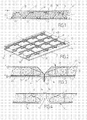
- Figure 1 and Figure 2 show, respectively in longitudinal section and in perspective, a reinforced concrete slab 1, of rectangular shape, with a longitudinal axis x'x and a transverse axis y'y.
- this slab is made by molding a concrete 10 in a formwork and has two outer faces called facing 11 and 12 between which extends a reinforcement cage 3 embedded in the concrete 10.
- the reinforcing cage has two layers of longitudinal and transverse bars, respectively placed at a minimum distance of coating of the outer faces 11 and 12 and interconnected by an internal reinforcement made of wire of smaller section, the number of bars of each sheet and their cross section being determined by a calculation of resistance of the materials according to the forces to be borne by the slab.
- the slab is subjected to an effort of bending under the effect, for example, of a vertical load, its lower face 11 is stretched and its upper face 12 is compressed and the sections of the reinforcing plies are calculated accordingly, in particular for the lower ply subjected to pulling forces.
- the slab produced according to the invention and shown in FIGS. 1 and 2 also comprises a reinforcement cage 3 consisting of thin strips but essentially differs from the arrangement described in the patent.
- EP 1 191 163 in that the main reinforcing ply, that is to say the ply which is placed, with respect to the neutral line, on the side of the stretch face 11 of the part, consists of a thin metal wall 2 covering at least a portion of the outer face 11 of the part 1 and having, therefore, an inner face 21 applied to the concrete 10 and on which are fixed corrugated strips 30 constituting the internal frame.
- the thin wall 2 which extends over the entire surface of the stretched face 11, thus constitutes a lost formwork facilitating the production of the element 1, in particular if it is prefabricated.
- the reinforcing ply On the compressed side of the piece 1, the reinforcing ply can be constituted, as in the arrangement described in the patent EP 1 191 163 longitudinal thin strips 31 interconnected by transverse strips 32.
- the corrugated strips 30 constituting the internal reinforcement are alternately welded or glued, by their apices 34, 35, respectively on the inner face 21 of the thin wall 2 and on the inner faces 31 'of the upper strips 31.
- the thickness e of the wall 2 is determined according to its width and in view of its mechanical characteristics, so as to obtain, in cross-section, a surface equivalent to that resulting from the calculation of the strength of the materials and which would be covered by a number of round section reinforcing bars, in the conventional technique or of several rectangular section flat strips, in the patent technique EP 1 191 163 .
- the thin wall 2 thus fulfills a dual role. On the one hand it forms, in a conventional way, a lost formwork for the realization of the slab and, on the other hand, it constitutes the main reinforcing ply resistant to the tensile forces generated in the lower part of the slab, under the effect of applied loads.
- this thin wall may also constitute a protective coating and, optionally, a sealing skin, for the outer face 11 of the slab.
- the longitudinal flat strips 31 and the corrugated strips 30 are conventionally arranged in several sections centered in planes P parallel to the longitudinal axis x'x of the slab and interconnected by the transverse strips 32 extending preferably below the longitudinal strips 31 and applied on their inner faces 31 '.
- the transverse strips 32 extending preferably below the longitudinal strips 31 and applied on their inner faces 31 '.
- the arrangement according to the invention makes it possible, by placing the main reinforcing ply at the external face 11 of the slab, to eliminate the thickness of concrete corresponding to the minimum coating distance and, thus, to reduce the overall thickness e1 of the beam.
- the thin wall 2 which constitutes the main reinforcing ply, is in contact with the concrete only on its inner face 21 but, because it extends over the entire surface of the element , the adhesion remains, still, much higher than that of round bars conventionally used. Therefore, when element 1 is subjected to bending resulting for example from the application of a vertical load, the thin wall 2 covering the stretched face 11 may lengthen slightly without risking the separation of the concrete, the adhesion effect being distributed over the entire surface of the face tense 11.
- the upper face 12 of the element is compressed, but it should be noted that if the corrugated strips 30 are welded to the upper armature 31 only by some of their vertices 35, the whole of the element can be deformed slightly while maintaining flexibility.
- This adhesion effect between the inner face 21 of the wall 2 and the concrete 10 can also be increased by subjecting this face 21 of the wall 2 to a suitable treatment.
- the thickness e1 could be further reduced by also producing the upper reinforcing ply in the form of a continuous thin wall covering the upper face 12 of the slab.
- reinforcing ply As the reinforcing ply is no longer covered with concrete, it is in contact with the external environment and can therefore oxidize if it is metal. However, the thin wall 2 being apparent, it is easy to check its state and possibly to remedy, for example by a protective treatment. On the other hand, in a conventional reinforced concrete part, reinforcing bars are concealed, precisely, by the coating concrete and their oxidation state often appears too late, when the concrete starts to burst.
- the strips 31 and 32 constituting the upper reinforcing ply and the corrugated strips 30 constituting the internal frame are advantageous, also, to make a metal of the same nature, for example stainless steel, the strips 31 and 32 constituting the upper reinforcing ply and the corrugated strips 30 constituting the internal frame.
- a metal of the same nature for example stainless steel
- the welding of metals of the same nature is more easily carried out, possibly by simple electrical contact and the production of the upper sheet of stainless metal strips can further reduce the coating thickness along the upper face 12 slab.
- the thin wall 2 may, if necessary, have a left profile obtained by stamping.
- the thin wall 2 covering the element 1 constitutes both a reinforcing ply and a protective skin
- such a tank will be buried at least partially, the embankment placed outside to balance the thrust of water or other fluid in the tank.
- the characteristics of the panels, the wall 2 which covers them and the flat strips constituting the reinforcement cage 3 will be determined so as to give the tank a structure enabling it to withstand the thrust of the water before backfill, by example for a leak test and, conversely, for ground and groundwater thrust, applied from the outside to the empty tank.
- Such a reservoir may have a circular or rectangular shape.
- the panels may be curved and, preferably, provided on their lateral sides of male and female parts forming a ball, so as to standardize the panel regardless of the diameter of the tank. It is also possible to use flat panels fixed laterally on vertical uprights.
- the invention also makes it possible to produce fluid transport conduits, in particular drinking water if the coating wall is made of stainless steel.
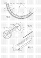
- FIG. 5 is a partial view, in cross section, of such a pipe comprising an inner lining wall 2, preferably of circular section, which constitutes a first reinforcing ply connected by corrugated strips 30, to a second ply consisting of longitudinal bars 31, parallel to the axis of the pipe and transverse bars 32 placed in planes perpendicular to the axis and constituting circular circles parallel to the outer face 12 of the pipe and separated therefrom by a minimum coating distance d.
- the corrugated bars 30 advantageously have the form of sinusoids and are arranged in a star in radial planes passing through the axis of the pipe.
- the reinforcing cage 3 comprising the inner wall 2, the outer ply 31, 32 and the corrugated strips 30 can also be calculated so as to withstand the forces applied from the outside by an embankment when the pipe is buried and does not is not subjected to internal pressure to compensate for the backfill load.
- the inner wall 2 as a reinforcing ply secured to the concrete 10 by the corrugated strips 30 and the outer ply 31, 32, it is possible to achieve, in this way, prefabricated sections provided, possibly, with attachment means for slings, the reinforcement cage 3 made according to the invention can be calculated so as to withstand the forces generated during transport.
- the invention also makes it possible to achieve, particularly advantageously, the casing of a water transport gallery, in particular for the renovation of an existing aqueduct.
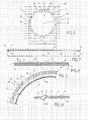
- FIG. 6 diagrammatically shows, in cross-section, a gallery G made for transporting water inside a solid mass M which can be compact or rocky terrain when the tunnel is made in a tunnel or a massive masonry, for example millstone or brick.
- a pipe for the transport of drinking water generally has a closed section to avoid the risk of pollution and evaporation of water.
- the gallery G is therefore limited by an internal face F having any cross section but, generally, circular, as indicated in the drawing, or for example, ovoid. Even when the massive support surrounding the gallery is made of masonry, the inner face F is relatively irregular and, moreover, more or less permeable. This face F must be covered with a plaster or plaster smooth and sealed to allow the flow of water without loss of load and without leakage, this coating must, furthermore, be adapted to the transport of drinking water.
- this coating is replaced by a thin metal wall 4, preferably made of stainless steel.
- an aqueduct it is particularly advantageous for an aqueduct to use, for the coating, such a metal that is most suitable for transporting water because it is completely neutral and resists corrosion perfectly.
- stainless steel sheets even in contact with water, remain shiny and smooth and allow easy flow with little swirl and loss of pressure.
- the diameter (d) of the coating wall 4 is a little smaller than the diameter (D) of the gallery so as to leave, between the wall 4 and the inner face F of the gallery, a space E into which is poured or injected, after the laying of the wall 4, a sealant such as a cement mortar or a concrete particle size fine enough to fill the entire space E whose thickness remains, obviously quite low, normally less than 10 cm.
- the lining wall 4 of the gallery is formed of a series of successive sections each consisting of a thin wall panel of substantially rectangular shape, wound around a longitudinal axis O.
- this coating wall 4 constitutes a reinforcing ply and its thickness is therefore determined, given the yield strength of the stainless steel, so as to withstand the foreseeable forces.
- an aqueduct operates with free flow and is therefore not under pressure, but the invention makes it possible, precisely, to operate under an internal pressure of the order of 1 or 2 bars, which makes it possible to increase the flow rate.
- the gallery G may be subjected to an external pressure, for example that of an embankment or the water table when it is buried.
- an external pressure for example that of an embankment or the water table when it is buried.
- the use, according to the invention, of a resistant metal wall to form the inner lining of the gallery makes it possible to withstand differential settlements which may cause cracking in the masonry galleries.
- the inner lining wall made of stainless steel sheet food grade, may have a thickness of about 1 to 1.5 mm.
- the coating may therefore consist of thin plates having a width corresponding to the perimeter of the gallery, for example 6m for a gallery 2 m in diameter and a length of 4 to 6 m, which depends, however, the layout of the gallery, it may have bends.
- the length L1 of a panel may be equal to the width of a strip delivered in a reel.
- the panel is cut on a coil unwound, its width L2 can be any.
- the width L2 of the panel will be substantially equal to or only slightly less than the circumference, in cross section, of the internal face F of the gallery so that, as shown in FIG. 6, after winding the panel about its longitudinal axis O, the two lateral sides 41 and 41 'of the panel 4, come into contact or overlap slightly or are covered with a seal cover 45 for their interlocking.
- FIG. 6 there is shown a gallery G circular section but the profile in cross section of the gallery, may be, for example, ovoid, or even have a flat bottom.
- each wound panel will have a cylindrical shape, the cylindrical term applying to any surface set with generatrices parallel to the longitudinal axis O.
- the plate 40 forming a panel is thus cut from the stainless steel coil and placed on two lateral sections 42, 42 'parallel to the longitudinal axis O and having a length substantially equal to the length L1 of the panel.
- the space E between the coating 4 and the internal face F of the gallery is not only filled with a sealant but also reinforced by a reinforcement 3 preferably comprising a plurality of longitudinals 30 spaced apart from each other. others and distributed over the entire width L2 of the panel.
- stirrups 30 are preferably each constituted by a corrugated metal strip which can thus be welded, by the tops of the undulations, to the upper face 43 'of the panel 40 which, after winding the panel, will constitute its face. external to the annular space E.
- these stirrups could also consist of separate strips of tape, welded or glued, at one end, to the wall 50 and extending in the space E between the metal wall 40 and the inner side F of gallery G.
- these corrugated stirrups 30 are arranged in planes parallel to the longitudinal axis O so that, after winding the panel 40, they are arranged in a star, in radial planes, as shown in Figure 6.
- the frame 3 is completed by transverse bars 32 which may be round irons but are preferably constituted by flat strips which are threaded into the corrugations of the stirrups 30, the level of their highest vertices.
- Each bar 32 is fixed only on one of the stirrups so as to slide relative to the other stirrups when the panel 40 is wound.
- the bars 32 form circular circles arranged in planes transverse to the longitudinal axis of winding O of the panel 40.
- the frame 3 can be further supplemented by transverse bars 33 which are bent so as to be applied on the internal face F of the gallery.
- the bars 33 can advantageously be fixed in the support mass 10 by connection means 36 associated with spacers enabling their position to be adjusted with respect to the internal face F so as to compensate for the irregularities of the -this.
- Each transverse bar 33 thus forms a kind of template on which the panel 40 comes to bear when it is unwound by the sockets of the corrugated stirrups 30.
- two metal strips 45, 45 ' are fixed on two perpendicular consecutive sides of the panel, for example a lateral side 41' (FIG. 7) and a transverse side 44 ', each strip 45, 45' being fixed on one half of its width so as to protrude from the panel to form a joint cover for fixing edge to edge the two lateral sides 41, 41 'of the same panel or the adjacent transverse edges of two consecutive sections.
- the panel 40 thus produced can be wound in the manner shown diagrammatically in FIG. 10.
- a winding tool 5 comprising for example two circular plates is used. 51 rotating about an axis 52 and on which can be fixed the ends of one of the profiles 42 '.
- the panel 40 is thus wound around the axis 52 by more than one turn so as to form a "surrouled" panel shown schematically in FIG. 13, whose diameter of is much smaller than the diameter D of the gallery.
- This surrouled panel can thus be introduced into the gallery, as will be described later and unwound, to achieve the cylindrical wall, the two sections 42, 42 'being side by side and the sides 41, 41' being in contact .
- a scrolling tool of the type shown in FIGS. 14, 15, 16 is advantageously used.
- this unwinding tool 6 comprises a central shaft 61 rotatably mounted about its axis on two bearings 62 fixed in rotation and each carrying two spaced arms 63, 63 ', the rotary shaft 61 also carrying an arm 64 , 64 'at each end.
- Each pair of arms is provided with a clamping member 65 shown schematically in FIG. 15 and comprising two jaws hinged about an axis and provided with bearing parts 65 'shaped so as to be clamped together on both sides. other of a lateral section 42 or 42 '.
- the panel After the winding of the panel 40 by means of the winding tool 5, the panel is temporarily held in the supersized position shown in Figure 11, for example by one or two outer belts not shown.
- the unrolling tool 6 is then threaded axially inside the overflow panel 40.
- a transport carriage such as a forklift truck 60 provided with a front end of a steerable frame on which is usually mounted vertically sliding a lifting frame 66 having two arms forming a fork.
- a lift truck 60 of this type by replacing the lifting fork with the unwinding tool 6, the central shaft 61 of which is fixed on the lifting frame sliding 66 and extends cantilevered forward.
- the unwinding tool 6 thus carried by the carriage 60 can be threaded axially inside the overlayed panel 40.
- the spacing of the arms 63, 63 'mounted on the bearings 62 and fixed in rotation is slightly greater than the length L1 of a panel so that the clamping jaws 65 'carried by the two arms 63, 63' can engage, respectively on both ends of the lateral beam 42 placed on the outer side of the 40.
- the fixed arm 65 'placed at the front end of the rotary shaft 61 may, moreover, be articulated about an axis orthogonal to the horizontal axis of the shaft 61.
- the two arms 64, 64 'mounted on the rotary shaft 61 are spaced a distance shorter than the length L1 of the panel 40 and their length is adjusted so that the jaws 65 placed at their ends can engage on the section 42 'disposed within the surrouled panel. The latter is thus supported by the unwinding tool in the manner shown schematically on the left part of FIG. 15.
- a forklift truck can have rather small dimensions and that, in particular, its overall height depends on the lifting amplitude. However, in the case of the invention, this amplitude is low. Therefore, the unwinding tool 6 can be mounted on a carriage of dimensions compatible with those of the gallery to be coated to be introduced inside thereof as shown in Figures 15 and 16.
- an aqueduct generally has a very large length of several tens of kilometers and, thanks to the invention, it is possible to provide in the support mass holes of sufficient size to introduce in the gallery a forklift 60 and / or a surrouled panel, the carriage being supported, by rolling members, on the lower part of the inner face F of the gallery.
- the insertion orifice can thus be arranged at a considerable distance from the place where the coating is placed and the carriage 60 carrying the unrolling tool 6 and the surrendered panel moves axially inside the gallery until In the laying position shown in FIG. 16. Since the covering consists of elementary sections placed end to end, the carriage 60 will preferably remain inside the gallery, with the surrendered panels being inserted into the gallery. one after the other in the gallery by the orifice formed in the ceiling of this one.
- FIG. 15 thus schematically shows an aqueduct consisting of a gallery G formed inside a support mass M and in which a coating 4 has already been produced, in successive sections, up to a transverse edge 44a formed at the rear end of the last section 4a of the coating 4, in a plane perpendicular to the axis of the gallery.
- the rotation of the movable arms 64 which determines the unwinding of the panel 40 in the manner indicated on the right part of FIG. 12, is then controlled until the internal section 42 'exceeds the position of the external section 22.
- the profile of the unrolled panel can be determined with some precision by the transverse bars 33 which form a template, this profile is not, moreover, not necessarily circular.
- both ends 44a, 44b can simply snap into each other and be contact welded.
- the lateral sides 41, 41 'of the panel 40 are not strictly parallel, the panel being slightly trapezoidal.
- the joints can also be glued, riveted or bolted, for example as shown in FIG.
- junction between the side edges of a panel can be provided by means of a joint cover 45 associated with a seal.
- a similar arrangement using a circular seal 45 'and a seal 46' can be used to join the adjacent ends 44a, 44b of the already laid-up section 4a and the new section 4b.
- At least the rotary arms 64 of the unwinding tool 6 have a variable length, for example by means of a telescopic assembly actuated by a jack and can therefore apply the new element against the face F of the gallery G at as it unfolds.
- the new section 4b is circularly plate on the section. previous 4b, to punch holes in the section 4a already installed by passing through the end 44b of the section 4b to be laid and through the glued joint 46 '.
- stainless rivets are placed in order to press the new section 4b and its seal glued against the previous section 4.
- the junction of the seal between the circular seal and the longitudinal joint can be realized in a conventional manner.
- the gallery is not always straight and it is sometimes necessary to arrange elbows.
- the junction between two pipes having angularly offset axes may be effected by means of a bend made in the factory according to the so-called "melon slices" technique used, for example, for the production of oil pipelines.
- the elements will be assembled and riveted together on the site as indicated above.
- the sealant filling the space E between the coating 2 and the inner face 11 of the gallery can be injected after the laying of several consecutive sections.
- injection holes are drilled in the factory at a low end of each section and vent holes are formed at the opposite high end.
- the injected material may be, for example, a very plastic 400 kg micro-concrete slurry. After opening all the injection holes and vents, this concrete grout is injected by the lower end and the injection is continued until the grout appears by the high vent hole which is then closed and the low injection points.
- the technique that has just been described makes it possible to quickly and inexpensively renew the coating of an existing aqueduct but could also be used advantageously for the construction of a new aqueduct.
- the coating could be made shortly after the construction of the gallery, the transport carriage 60 then being introduced simply by the open end thereof.
- the panels 40 provided with their profiles 42 and frames 31, 32 can be made flat from a stainless steel coil.
- the panels thus produced can also be transported flat before surroulding. In this case, their dimensions must respect the road gauge.
- Such a surroulded panel may have a unit weight of about 400 to 500 kg, which corresponds to the lifting capacity of a small forklift conventional type.
- the invention has been described in the case of a slab, with reference to FIGS. 1 and 2, but it can be applied to other types of parts such as beams or hulls curved, the two outer walls 11 and 12 are not necessarily parallel.
- the inner armature 3 welded to the metal wall 2 which constitutes the outer armor ply, could be made differently.
- the technique according to the invention is not limited to the production of prefabricated parts.
- the wall 2 constituting a lost formwork and having, with the corrugated strips 30, a certain rigidity could for example, to make a wall, to pose two vertical walls apart by alternating the corrugated strips to allow their nesting and flow in this concrete space according to a technique similar to that of hereh concrete.
Abstract
Description
L'invention a pour objet un élément de construction armé et résistant, réalisé en une matière moulée, en particulier du béton, dans laquelle est noyée une armature de renforcement.The subject of the invention is a reinforced and resistant construction element made of a molded material, in particular concrete, in which a reinforcing reinforcement is embedded.
La technique du béton armé est connue depuis très longtemps pour la réalisation de pièces de toutes sortes telles que dalles, coques ou poutres soumises, en particulier, à des efforts de flexion, mais on réalise aussi de cette façon des conduites de transport de fluide, en particulier de grand diamètre.The technique of reinforced concrete has been known for a very long time for the production of parts of all kinds such as slabs, shells or beams subject, in particular, to bending forces, but in this way, fluid transport lines are also produced. especially of large diameter.
D'une façon générale, on réalise tout d'abord une armature métallique dite cage de ferraillage, qui, dans le cas de pièces préfabriquées, est placée dans un moule dont le fond forme un coffrage pour la coulée du béton à l'état fluide afin d'y noyer la cage de ferraillage, l'ensemble étant solidarisé ensuite par le durcissement du béton.In a general manner, a metal reinforcement called "reinforcement cage" is first made, which, in the case of prefabricated parts, is placed in a mold whose bottom forms a formwork for pouring concrete in a fluid state. in order to embed the reinforcement cage therein, the assembly being subsequently secured by the hardening of the concrete.
Dans la technique dite du béton banché, l'armature est placée entre deux parois de coffrage qui sont retirées après le durcissement du béton.In the so-called reinforced concrete technique, the reinforcement is placed between two shuttering walls which are removed after the concrete has hardened.
Dans certains cas, cependant, il est intéressant de conserver la paroi ayant servi de coffrage, par exemple pour assurer l'étanchéité ou sceller dans le béton une paroi constituant la face externe de la pièce.In some cases, however, it is interesting to keep the wall used as formwork, for example to seal or seal in concrete a wall constituting the outer face of the room.
Une telle technique dite de coffrage perdu est connu depuis très longtemps et, par exemple, le document
Cette paroi ondulée est simplement solidarisée avec le béton par des bandes formant des étriers de liaison s'étendant dans l'épaisseur du plancher. Un tel plancher n'est donc pas prévu pour résister à des charges importantes, d'autant plus que les efforts transversaux dits "poussée au vide" peuvent provoquer un léger décollement du béton. En outre, une paroi ondulée ne peut pas résister à des efforts de traction dans le sens transversal qui risqueraient également de provoquer un décollement du béton.This corrugated wall is simply secured to the concrete by strips forming connecting stirrups extending in the thickness of the floor. Such a floor is not designed to withstand heavy loads, especially since the transverse forces called "vacuum push" can cause a slight detachment of the concrete. In addition, a corrugated wall can not withstand tensile forces in the transverse direction that could also cause a detachment of the concrete.
Il est donc préférable, pour réaliser un élément de construction capable de résister aux efforts de flexion résultant des charges appliquées, de noyer dans le béton une cage d'armature métallique calculée de façon classique, pour résister aux efforts de traction engendrés par les charges appliquées sur la pièce alors que le béton résiste aux efforts de compression, la liaison entre le béton et l'armature permettant un transfert des efforts de l'un à l'autre des deux matériaux associés en raison de leur adhérence qui peut, d'ailleurs, être améliorée en utilisant, par exemple, des barres crantées.It is therefore preferable, to achieve a construction element capable of withstanding the bending forces resulting from the loads applied, to drown in the concrete a conventionally calculated metal reinforcement cage, to withstand the tensile forces generated by the loads applied to the part while the concrete is resistant to compressive forces, the connection between the concrete and the reinforcement allowing a transfer of forces from one to the other of the two associated materials because of their adhesion which can, moreover, be improved by using, for example, toothed bars.
Généralement, un élément de construction en béton armé comporte donc au moins une nappe d'armature sensiblement parallèle à une face externe de la pièce et solidarisée avec le béton par une armature interne enrobée dans celui-ci.Generally, a reinforced concrete construction element therefore comprises at least one reinforcement ply substantially parallel to an outer face of the part and secured to the concrete by an internal reinforcement embedded therein.
Dans le cas habituel d'une pièce, par exemple en forme de poutre ou de panneau ayant deux faces externes écartées l'une de l'autre, l'armature comporte, habituellement, deux nappes sensiblement parallèles à chaque face de la pièce et reliées par des étriers, l'ensemble étant noyé dans le béton.In the usual case of a part, for example in the form of a beam or panel having two outer faces spaced apart from each other, the reinforcement usually comprises two sheets substantially parallel to each face of the piece and connected to each other. by stirrups, all being embedded in the concrete.
L'armature est réalisée, habituellement, en acier et est donc sensible à l'oxydation. C'est pourquoi, normalement, chaque nappe d'armature doit être maintenue écartée de la face externe correspondante de la pièce par une couche de béton permettant d'assurer la protection de l'armature contre l'humidité. Cependant, il est difficile d'éviter une légère fissuration de la face externe de la pièce qui entraîne des venues d'eau au contact du métal avec un risque d'oxydation et, par conséquent, d'éclatement du béton, ce qui augmente les venues d'eau et peut conduire à la ruine de la pièce.The reinforcement is usually made of steel and is therefore sensitive to oxidation. This is why, normally, each reinforcing ply must be kept away from the corresponding outer face of the piece by a layer of concrete to ensure the protection of the frame against moisture. However, it is difficult to avoid a slight cracking of the outer face of the part which causes water coming into contact with the metal with a risk of oxidation and, consequently, bursting of the concrete, which increases the come from water and can lead to the ruin of the room.
C'est pourquoi la réglementation impose l'existence d'une épaisseur minimale d'enrobage, normalement 30 mm, entre une armature métallique et la face de parement correspondante de la pièce.This is why the regulation imposes the existence of a minimum thickness of coating, normally 30 mm, between a metal reinforcement and the corresponding facing face of the part.
Habituellement, une cage de ferraillage est constituée de deux nappes d'armature constituées de barres rondes et reliées entre elles par des étriers ou des épingles formant une armature interne constituée de fers de plus faible diamètre entourant les barres principales.Usually, a reinforcement cage consists of two reinforcing plies made of round bars and interconnected by stirrups or pins forming an internal frame made of smaller diameter irons surrounding the main bars.
Pour maintenir la distance minimale d'enrobage requise, il faut donc positionner avec précision les armatures à l'intérieur de la pièce moulée, en utilisant des écarteurs prenant appui sur le coffrage, mais il faut tenir compte du diamètre des étriers qui entourent les barres.To maintain the minimum required coating distance, it is therefore necessary to accurately position the reinforcements inside the molded part, using spacers supported on the formwork, but the diameter of the stirrups surrounding the bars must be taken into account. .
Cette distance minimale d'enrobage, qui doit être maintenue sur les deux faces de la pièce, augmente l'épaisseur de celle-ci alors que l'épaisseur utile, permettant d'assurer la résistance de la pièce, correspond seulement à la distance entre les deux nappes d'armature.This minimum coating distance, which must be maintained on both sides of the part, increases the thickness thereof while the useful thickness, to ensure the strength of the part, is only the distance between the two reinforcing plies.
Il est avantageux, cependant, de réduire autant que possible l'épaisseur des pièces en béton, en particulier, dans les techniques de préfabrication lourde dans lesquelles on réalise à l'avance des pièces d'assez grandes dimensions qui doivent être manipulées par des engins de levage. D'autre part, la quantité de béton utilisée représente une part importante du coût d'une pièce et il est avantageux de chercher à la réduire en conservant la même résistance.It is advantageous, however, to reduce as much as possible the thickness of the concrete parts, in particular, in heavy prefabrication techniques in which are made in advance pieces of rather large dimensions which must be handled by machines lifting. On the other hand, the amount of concrete used represents a significant part of the cost of a part and it is advantageous to seek to reduce it while maintaining the same resistance.
A cet effet, le même inventeur a déjà proposé, dans la demande de brevet
Dans cette technique, les barres d'armatures ne sont pas constituées, comme habituellement, de fers ronds mais de bandes plates de section rectangulaire ayant une face large parallèle à la face de parement correspondante de la pièce. Chaque bande plate présente une section transversale équivalente à celle d'une barre ronde calculée pour résister aux efforts appliqués mais sa forme rectangulaire permet de fixer facilement, sur sa face interne, par soudure, les fers formant l'armature interne et constitués, eux-mêmes, avantageusement, de bandes plates. Ainsi, il n'est pas nécessaire que de tels étriers entourent les barres principales et l'on peut donc diminuer la distance d'enrobage et, par conséquent, l'épaisseur globale de la pièce.In this technique, the reinforcing bars do not consist, as usually, round irons but flat strips of rectangular section having a broad face parallel to the corresponding facing face of the workpiece. Each flat strip has a cross section equivalent to that of a round bar calculated to withstand the forces applied but its rectangular shape makes it easy to fix, on its inner face, by welding, the irons forming the internal frame and constituted, themselves same, advantageously, flat strips. Thus, it is not necessary that such stirrups surround the main bars and thus the coating distance and, consequently, the overall thickness of the workpiece can be reduced.
On avait déjà proposé, dans le document
Une technique de ce genre avait déjà été employée pour la réalisation de parois d'aéronefs à la fois légères, rigides et isolantes, mais on pourrait difficilement l'appliquer à la réalisation de pièces en béton armé.A technique of this kind had already been used for the construction of aircraft walls at the same time light, rigid and insulating, but it could hardly be applied to the realization of reinforced concrete parts.
La technique décrite, en revanche, dans la demande brevet précédente
Un autre avantage de cette technique nouvelle réside dans le fait qu'une bande plate à section rectangulaire présente un périmètre bien supérieur à celui d'une ou deux barres rondes ayant une section transversale équivalente, le rapport pouvant être, par exemple, de 1,6. Il en résulte que l'adhérence entre l'armature et le béton, qui dépend, précisément, du périmètre, est augmentée dans les mêmes proportions qui correspondent sensiblement à l'avantage apporté, dans le béton armé, par l'utilisation de barres crantées ou de fers TOR.Another advantage of this novel technique lies in the fact that a rectangular section flat strip has a perimeter much greater than that of one or two round bars having an equivalent cross section, the ratio being, for example, 1, 6. As a result, the adhesion between the reinforcement and the concrete, which depends, precisely, on the perimeter, is increased in the same proportions which correspond substantially to the advantage provided, in the reinforced concrete, by the use of notched bars. or TOR irons.
Ainsi, l'adhérence entre les barres d'armature et le béton, dont dépend le transfert des efforts de traction, est sensiblement la même pour des bandes plates que pour des fers crantés.Thus, the adhesion between the reinforcing bars and the concrete, on which the transfer of tensile forces depends, is substantially the same for flat strips as for notched irons.
Or, on sait que, lorsque la pièce est soumise à des efforts de flexion importants, les barres de la nappe d'armature principale placées à une faible distance de la face tendue, ont tendance à s'allonger et, du fait que les parties crantées, légèrement espacées, sont bloquées par rapport au béton, il en résulte, à leur niveau, l'apparition de fissures qui, à la longue, peuvent provoquer des venues d'eau et la corrosion de l'armature.However, it is known that, when the part is subjected to significant bending forces, the bars of the main reinforcing ply placed at a short distance from the stretched face, tend to lengthen and, because the parts notched, slightly spaced, are blocked relative to the concrete, it results, at their level, the appearance of cracks that, in the long run, can cause water inflow and corrosion of the frame.
Lorsque, au contraire, on utilise des bandes plates de la façon décrite dans le document
Cependant, même si le risque de fissuration est diminué, le béton d'enrobage ne peut pas assurer une étanchéité absolue lorsque le risque de venue d'eau est important, en particulier dans le cas de conduites de transport de liquide ou bien chaque fois que l'élément de construction, par exemple mur ou plancher, est placé dans une atmosphère humide. Bien entendu, le risque est encore accru dans le cas de conduites ou de réservoirs contenant des produits nocifs et corrosifs.However, even if the risk of cracking is reduced, the embedding concrete can not ensure an absolute seal when the risk of water coming in is important, in particular in the case of liquid transport pipes or whenever the building element, for example wall or floor, is placed in a humid atmosphere. Of course, the risk is further increased in the case of pipes or tanks containing harmful and corrosive products.
De même dans le cas de conduites de transport d'eau potable, tels que des aqueducs, la paroi en maçonnerie ou en béton de la galerie doit être recouverte d'un revêtement étanche tel qu'un enduit apte au transport d'eau potable, qui doit être nettoyé et parfois remplacé entièrement.Similarly in the case of drinking water transmission pipes, such as aqueducts, the wall of masonry or concrete of the gallery must be covered with a waterproof coating such as a coating suitable for the transport of drinking water, which needs to be cleaned and sometimes completely replaced.
En outre, les aqueducs utilisés pour l'alimentation en eau des villes sont généralement assez anciens et, par suite de tassements différentiels, il peut apparaître des fissures qui provoquent des pertes d'eau importantes et un risque de pollution.In addition, aqueducts used for water supply in cities are generally quite old and, as a result of differential settlements, cracks can appear which cause significant water losses and a risk of pollution.
L'invention a donc pour objet de nouveaux développements de la technique décrite dans le brevet
L'invention concerne donc, d'une façon générale, un élément de construction constitué d'un panneau en béton armé dans lequel est noyée une armature de renforcement comportant au moins une nappe d'armature principale s'étendant le long d'une face externe tendue de l'élément et sur laquelle est fixée une armature interne de solidarisation avec le béton, s'étendant dans l'épaisseur de l'élément, ce dernier étant réalisé, après la pose de l'armature de renforcement, par coulée de béton sur une paroi mince continue formant un coffrage perdu.The invention therefore generally relates to a construction element consisting of a reinforced concrete panel in which is embedded a reinforcing reinforcement comprising at least one main reinforcing ply extending along one face. external tension of the element and on which is fixed an internal reinforcing reinforcement with the concrete, extending in the thickness of the element, the latter being formed, after the laying of the reinforcing reinforcement, by casting of concrete on a continuous thin wall forming a lost formwork.
Conformément à l'invention, la paroi mince formant le coffrage perdu s'étend le long de la face tendue de l'élément et constitue en même temps la nappe d'armature principale de l'élément, la nature et l'épaisseur de ladite paroi mince étant déterminées de façon à résister aux contraintes de traction engendrées par les efforts appliqués sur l'élément sans risque de décollement du béton.According to the invention, the thin wall forming the lost formwork extends along the stretched face of the element and at the same time constitutes the principal reinforcing ply of the element, the nature and the thickness of said element. thin wall being determined so as to withstand the tensile stresses generated by the forces applied to the element without risk of detachment of the concrete.
Dans un mode de réalisation préférentiel, la paroi mince formant la nappe d'armature principale et recouvrant la face externe tendue de la pièce, constitue une peau d'étanchéité continue.In a preferred embodiment, the thin wall forming the main reinforcing ply and covering the taut outer face of the part, constitutes a continuous sealing skin.
Ainsi, alors que dans le brevet antérieur
Bien entendu, la paroi mince servant, ainsi, d'armature principale doit être capable de résister à la corrosion et, pour cela, elle peut être réalisée en un métal inoxydable ou à base de fibres de verre ou de carbone, ou bien recouverte d'un revêtement adéquat, l'augmentation de prix qui en résulte pouvant être compensée par les avantages apportés par l'invention.Of course, the thin wall thus serving as the main reinforcement must be capable of resisting corrosion and for this purpose it may be made of a stainless metal or based on glass or carbon fibers, or covered with a suitable coating, the resulting price increase being able to be offset by the advantages provided by the invention.
L'invention permet la réalisation de pièces du genre dalle ou coque mais peut aussi s'appliquer avantageusement à la réalisation de conduites de circulation d'un fluide corrosif ou bien de transport d'eau potable et d'une façon générale, de toute structure étanche, par exemple coque de navire, péniche ou autre objet flottant.The invention allows the production of parts of the slab or shell type but can also be advantageously applied to the production of corrosive fluid circulation lines or of drinking water transport and in general, of any structure waterproof, for example hull of ship, barge or other floating object.
En particulier, l'invention permet la réalisation d'un revêtement étanche dans une galerie maçonnée ou creusée dans le terrain naturel, ledit revêtement comportant une paroi mince introduite à l'intérieur de la galerie et séparée de la face interne de celle-ci par un espace dans lequel est injecté une matière moulable résistante telle que du béton, dans laquelle est noyée une armature interne de solidarisation.In particular, the invention allows the realization of a waterproof coating in a gallery built or excavated in the natural terrain, said coating having a thin wall introduced into the gallery and separated from the inner face thereof by a space in which is injected a moldable resistant material such as concrete, which is embedded in an internal reinforcing frame.
Conformément à l'invention, les caractéristiques dimensionnelles et structurelles de la paroi mince et de l'armature interne sont déterminées de façon que l'ensemble du revêtement soit capable de résister aux efforts appliqués résultant des poussées externes, de la pression en service et de tassements différentiels éventuels de la galerie.According to the invention, the dimensional and structural characteristics of the thin wall and the internal reinforcement are determined so that the entire coating is able to resist the forces applied as a result of external thrust, service pressure and eventual settlement of the tunnel.
De façon particulièrement avantageuse, l'armature interne est constituée d'une pluralité de bandes ondulées parallèles à l'axe longitudinal (0) de la conduite et réparties autour de celui-ci, lesdites bandes étant soudées par au moins certains des sommets des ondulations sur la face interne de la paroi mince.Particularly advantageously, the internal reinforcement consists of a plurality of corrugated strips parallel to the longitudinal axis (0) of the pipe and distributed around it, said strips being welded by at least some of the peaks of the corrugations. on the inner side of the thin wall.
Dans un mode de réalisation préférentiel, le revêtement est constitué de tronçons successifs comportant chacun un panneau de paroi mince rectangulaire ayant une longueur correspondant à la longueur du tronçon et une largeur correspondant au périmètre de la conduite en section transversale. Ce panneau est d'abord posé à plat pour placer sur une face supérieure une armature interne comportant au moins une pluralité de bandes ondulées parallèles à un axe longitudinal du panneau et écartées l'une de l'autre, lesdites bandes étant soudées sur la face supérieure du panneau par au moins certains des sommets des ondulations; le panneau est ensuite surroulé pour former un tube de diamètre global inférieur à celui de la galerie les bandes ondulées étant tournées vers l'extérieur, et le panneau surroulé est introduit dans la galerie jusqu'à l'emplacement de pose et est déroulé de façon à prendre appui sur la face latérale par les sommets des bandes ondulées de la galerie; le panneau est alors soudé, d'une part le long de deux côtés longitudinaux venus en contact et d'autre part, le long d'un côté transversal extrême, avec le côté extrême correspondant du dernier tronçon déjà posé, et une matière moulable telle que du béton est injectée dans l'espace entre la paroi mince et la face latérale de la galerie, afin de noyer l'armature interne et de solidariser l'ensemble.In a preferred embodiment, the coating consists of successive sections each having a rectangular thin wall panel having a length corresponding to the length of the section and a width corresponding to the perimeter of the cross section pipe. This panel is first laid flat to place on an upper face an internal frame having at least a plurality of corrugated strips parallel to a longitudinal axis of the panel and spaced apart from each other, said strips being welded on the face upper panel by at least some of the peaks of the corrugations; the panel is then supersized to form a tube of overall diameter smaller than that of the gallery, the corrugated strips being turned outwards, and the overdrawn panel is introduced into the gallery to the installation location and is unrolled to be supported on the lateral face by the summits of the corrugated strips of the gallery; the panel is then welded, on the one hand along two longitudinal sides come into contact and on the other hand, along an extreme transverse side, with the corresponding extreme side of the last section already laid, and a molding material such as concrete is injected into the space between the thin wall and the side face of the gallery, to drown the internal frame and to secure the assembly.
L'invention couvre également l'outillage utilisé pour la mise en oeuvre du procédé.The invention also covers the tools used for the implementation of the method.
En effet, après la réalisation, à plat, du panneau muni des bandes ondulées constituant l'armature interne, ce panneau est surroulé au moyen d'un outil d'enroulement comprenant deux plateaux circulaires tournant autour d'un axe, sur lesquels sont fixées les extrémités d'un profilé ménagé sur l'un des cotés longitudinaux du panneau qui est enroulé sur plus d'un tour par rotation des plateaux autour de leur axe.Indeed, after the realization, flat, of the panel provided with corrugated strips constituting the internal frame, this panel is surrouled by means of a winding tool comprising two circular plates rotating about an axis, on which are fixed the ends of a profile formed on one of the longitudinal sides of the panel which is wound on more than one turn by rotation of the plates around their axis.
Ensuite, ce panneau surroulé est introduit dans la galerie au moyen d'un outil de déroulement comportant un arbre central portant, à ses extrémités, deux bras mobiles et monté rotatif sur deux paliers fixes en rotation, portant respectivement deux bras écartés dont l'écartement est un peu supérieur à la longueur d'un panneau, chaque paire de bras étant munie d'un organe de serrage ; l'outil de déroulement est alors enfilé dans le panneau surroulé de façon que les organes de serrage portés respectivement par les bras des paliers s'engagent sur les extrémités d'un profilé latéral placé sur le coté externe du panneau surroulé alors que les organes de serrage des bras de l'arbre central s'engagent sur les extrémités d'un profilé placé sur le coté interne du panneau surroulé, puis ledit panneau est placé dans sa position de pose par avancement de l'outil à l'intérieur de la galerie puis est déroulé par rotation des bras mobiles jusqu'à ce que le profilé interne dépasse la position du profilé externe, et l'on procède alors à la jonction étanche des bords en vis-à-vis du panneau le long des cotés latéraux, ainsi que des cotés transversaux adjacents, respectivement du dernier tronçon déjà posé et du nouveau tronçon.Then, this surrouled panel is introduced into the gallery by means of a unwinding tool comprising a central shaft bearing, at its ends, two movable arms and rotatably mounted on two fixed bearings in rotation, respectively carrying two arms apart whose spacing is slightly greater than the length of a panel, each pair of arms being provided with a clamping member; the unwinding tool is then threaded into the over-inflated panel so that the clamping members carried respectively by the arms of the bearings engage on the ends of a lateral profile placed on the outer side of the superspreaded panel while the clamping of the arms of the central shaft engage on the ends of a profile placed on the inner side of the surrouled panel, and said panel is placed in its installation position by advancing the tool inside the gallery then is unrolled by rotation of the movable arms until the inner section exceeds the position of the outer section, and then the sealing of the edges opposite the panel along the lateral sides is effected, and only adjacent transverse sides, respectively of the last section already laid and the new section.
Dans un mode de réalisation préférentiel, l'outil de déroulement est monté sur un chariot de transport tel qu'un chariot élévateur, de dimensions compatibles avec celles de la galerie à revêtir, afin d'être introduit à l'intérieur de celle-ci.In a preferred embodiment, the unwinding tool is mounted on a transport carriage such as a forklift, of dimensions compatible with those of the gallery to be coated, in order to be introduced inside thereof. .
Mais l'invention couvre également d'autres applications et d'autres caractéristiques avantageuses qui apparaîtront dans la description qui va suivre de certains modes de réalisation particuliers donnés à titre d'exemple et représentés sur les dessins annexés.
- La figure 1 est une vue partielle en coupe d'une pièce composite selon l'invention.
- La figure 2 montre schématiquement, en perspective, la constitution d'une dalle selon l'invention.
- La figure 3 montre, en coupe horizontale, la jonction entre deux panneaux formant une paroi de réservoir.
- La figure 4 montre un autre mode de réalisation de la jonction entre deux panneaux de paroi.
- La figure 5 est une vue partielle, en coupe, d'une paroi de conduite réalisée selon l'invention.
- La figure 6 est une vue schématique, en coupe transversale, d'une galerie munie d'un revêtement selon l'invention.
- La figure 7 est une vue en coupe transversale d'un panneau de revêtement posé à plat.
- La figure 8 est une vue en coupe longitudinale du panneau de revêtement.
- La figure 9 est une vue partielle, à échelle agrandie, du revêtement et de son armature.
- La figure 10 montre schématiquement, en perspective, le processus d'enroulement d'un panneau de revêtement.
- La figure 11 montre, en perspective, un panneau surroulé
- La figure 12 montre le fonctionnement d'un outil de déroulement, en deux étapes successives.
- La figure 13 est une vue de détail d'une mâchoire de serrage.
- La figure 14 montre un chariot de transport équipé d'un outil de déroulement.
- Les figures 15 et 16 illustrent schématiquement la pose d'un nouvel élément de paroi à l'intérieur d'une galerie.
- La figure 17 est une vue de détail de l'emboîtement entre deux éléments consécutifs.
- La figure 18 montre schématiquement la réalisation d'une jonction étanche entre deux éléments successifs de revêtement.
- Figure 1 is a partial sectional view of a composite part according to the invention.
- Figure 2 shows schematically, in perspective, the constitution of a slab according to the invention.
- Figure 3 shows, in horizontal section, the junction between two panels forming a tank wall.
- Figure 4 shows another embodiment of the junction between two wall panels.
- Figure 5 is a partial view, in section, of a pipe wall made according to the invention.
- Figure 6 is a schematic view, in cross section, of a gallery provided with a coating according to the invention.
- Figure 7 is a cross-sectional view of a cladding board laid flat.
- Figure 8 is a longitudinal sectional view of the cladding panel.
- Figure 9 is a partial view, on an enlarged scale, of the coating and its frame.
- Figure 10 shows schematically, in perspective, the winding process of a cladding panel.
- Figure 11 shows, in perspective, a surrouled panel
- Figure 12 shows the operation of a scrolling tool in two successive steps.
- Figure 13 is a detail view of a clamping jaw.
- Figure 14 shows a transport carriage equipped with a unwinding tool.
- Figures 15 and 16 schematically illustrate the installation of a new wall element inside a gallery.
- Figure 17 is a detailed view of the interlocking between two consecutive elements.
- Figure 18 schematically shows the realization of a sealed junction between two successive elements of coating.
La figure 1 et la figure 2 montrent, respectivement en coupe longitudinale et en perspective, une dalle en béton armé 1, de forme rectangulaire, avec un axe longitudinal x'x et un axe transversal y'y. Comme habituellement, cette dalle est réalisée par moulage d'un béton 10 dans un coffrage et présente deux faces externes dites de parement 11 et 12 entre lesquelles s'étend une cage d'armature 3 noyées dans le béton 10.Figure 1 and Figure 2 show, respectively in longitudinal section and in perspective, a reinforced
Habituellement, la cage d'armature présente deux nappes de barres longitudinales et transversales, placées respectivement à une distance minimale d'enrobage des faces externes 11 et 12 et reliées entre elles par une armature interne constituées d' réalisés en fil de plus faible section, le nombre de barres de chaque nappe et leur section transversale étant déterminés par un calcul de résistance des matériaux en fonction des efforts à supporter par la dalle. En particulier, si la dalle est soumise à un effort de flexion sous l'effet, par exemple, d'une charge verticale, sa face inférieure 11 est tendue et sa face supérieure 12 est comprimée et les sections des nappes d'armature sont calculées en conséquence, en particulier pour la nappe inférieure soumise à des efforts de traction.Usually, the reinforcing cage has two layers of longitudinal and transverse bars, respectively placed at a minimum distance of coating of the outer faces 11 and 12 and interconnected by an internal reinforcement made of wire of smaller section, the number of bars of each sheet and their cross section being determined by a calculation of resistance of the materials according to the forces to be borne by the slab. In particular, if the slab is subjected to an effort of bending under the effect, for example, of a vertical load, its
Comme on l'a exposé dans le brevet
La dalle réalisée selon l'invention et représentée sur les figures 1 et 2, comporte également une cage d'armature 3 constituée de bandes minces mais diffère essentiellement de la disposition décrite dans le brevet
La paroi mince 2, qui s'étend sur toute la surface de la face tendue 11, constitue ainsi un coffrage perdu facilitant la réalisation de l'élément 1, en particulier si celui-ci est préfabriqué.The
Sur le côté comprimé de la pièce 1, la nappe d'armature peut être constituée, comme dans la disposition décrite dans le brevet
Les bandes ondulées 30 constituant l'armature interne sont soudées ou collées alternativement, par leurs sommets 34, 35, respectivement sur la face interne 21 de la paroi mince 2 et sur les faces internes 31' des bandes supérieures 31.The corrugated strips 30 constituting the internal reinforcement are alternately welded or glued, by their
Selon l'invention l'épaisseur e de la paroi 2 est déterminée en fonction de sa largeur et compte-tenu de ses caractéristiques mécaniques, de façon à obtenir, en section transversale, une surface équivalente à celle résultant du calcul de résistance des matériaux et qui serait couverte par un certain nombre de barres d'armatures à section ronde, dans la technique classique ou bien de plusieurs bandes plates à section rectangulaire, dans la technique du brevet
La paroi mince 2 remplit donc un double rôle. D'une part elle forme, de façon classique, un coffrage perdu pour la réalisation de la dalle et, d'autre part elle constitue la nappe d'armature principale résistant aux efforts de traction engendrés dans la partie inférieure de la dalle, sous l'effet des charges appliquées. En outre, cette paroi mince peut aussi constituer un revêtement protecteur et, éventuellement, une peau d'étanchéité, pour la face externe 11 de la dalle.The
Comme le montre la figure 2, les bandes plates longitudinales 31 et les bandes ondulées 30 sont disposées, de façon classique, en plusieurs sections centrées dans des plans P parallèles à l'axe longitudinal x'x de la dalle et reliées entre elles par les bande transversales 32 s'étendant, de préférence, au-dessous des bandes longitudinales 31 et appliquées sur leurs faces internes 31'. En revanche, au niveau inférieur, aucune armature transversale n'est nécessaire puisque l'ensemble de la nappe d'armature principale est constitué par la paroi continue 2.As shown in FIG. 2, the longitudinal
La disposition selon l'invention permet, en plaçant la nappe d'armature principale au niveau de la face externe 11 de la dalle, de supprimer l'épaisseur de béton correspondant à la distance minimale d'enrobage et, ainsi, de réduire l'épaisseur globale e1 de la poutre.The arrangement according to the invention makes it possible, by placing the main reinforcing ply at the
Par ailleurs, comme on l'a indiqué plus haut, l'utilisation de bandes plates comme barres d'armature longitudinales permet, à section équivalente, d'augmenter sensiblement le périmètre et d'avoir, ainsi, une adhérence du même ordre que celle d'une barre crantée.Moreover, as mentioned above, the use of flat strips as longitudinal reinforcing bars makes it possible, in equivalent section, to substantially increase the perimeter and thus to have an adhesion of the same order as that a notched bar.
Dans l'invention, la paroi mince 2 qui constitue la nappe d'armature principale, n'est en contact avec le béton que sur sa face interne 21 mais, du fait qu'elle s'étend sur toute la surface de l'élément, l'adhérence reste, encore, bien supérieure à celle des barres rondes utilisées de façon classique. Par conséquent, lorsque l'élément 1 est soumis à des efforts de flexion résultant par exemple de l'application d'une charge verticale, la paroi mince 2 recouvrant la face tendue 11 peut s'allonger légèrement sans risquer le décollement du béton, l'effet d'adhérence étant réparti sur toute la surface de la face tendue 11.In the invention, the
Dans ce cas, la face supérieure 12 de l'élément est comprimée, mais il est à noter que si les bandes ondulées 30 ne sont soudées sur l'armature supérieure 31 que par certains de leurs sommets 35, l'ensemble de l'élément peut se déformer légèrement en conservant une certaine souplesse.In this case, the
Cet effet d'adhérence entre la face interne 21 de la paroi 2 et le béton 10 peut d'ailleurs être augmenté en faisant subir un traitement adéquat à cette face 21 de la paroi 2.This adhesion effect between the
On sait, par exemple, que, à la fin du laminage, il est possible, dans un traitement de surface ou un laminage dit de "skin pass", de donner à la tôle une qualité de surface particulière, par exemple en réalisant de légères stries permettant d'augmenter l'adhérence.It is known, for example, that, at the end of the rolling, it is possible, in a surface treatment or so-called "skin pass" lamination, to give the sheet a particular surface quality, for example by producing light weight streaks to increase adhesion.
Selon une variante, l'épaisseur e1 pourrait encore être diminuée en réalisant également la nappe d'armature supérieure sous forme d'une paroi mince continue recouvrant la face supérieure 12 de la dalle.According to one variant, the thickness e1 could be further reduced by also producing the upper reinforcing ply in the form of a continuous thin wall covering the
Comme la nappe d'armature n'est plus recouverte de béton, elle se trouve au contact du milieu extérieur et peut donc s'oxyder si elle est en métal. Toutefois, la paroi mince 2 étant apparente, il est facile de vérifier son état et, éventuellement, d'y remédier, par exemple par un traitement de protection. En revanche, dans une pièce en béton armé classique, les barres d'armatures sont cachées, précisément, par le béton d'enrobage et leur état d'oxydation apparaît souvent trop tard, lorsque le béton commence à éclater.As the reinforcing ply is no longer covered with concrete, it is in contact with the external environment and can therefore oxidize if it is metal. However, the
D'ailleurs, du fait que la paroi 2 est placée à l'extérieur, on peut la recouvrir d'un revêtement protecteur, comme une peinture, ou bien utiliser des tôles galvanisées ou en métal inoxydable.Moreover, because the
En effet, l'invention apporte de tels avantages, par la réduction de la quantité de béton utilisée et par l'utilisation de la nappe d'armature comme coffrage perdu et peau de protection et/ou d'étanchéité, qu'il sera souvent rentable de réaliser celle-ci en acier inoxydable, d'autant plus que la répartition des efforts de traction sur toute la largeur de la paroi mince 2, c'est-à-dire, éventuellement, sur toute la largeur de l'élément 1, permet d'obtenir la section transversale nécessaire avec une très faible épaisseur.Indeed, the invention provides such advantages, by reducing the amount of concrete used and the use of the reinforcing ply as lost formwork and skin protection and / or sealing, it will often cost effective to achieve it in stainless steel, especially as the distribution of tensile forces over the entire width of the
De même, en raison des avantages apportés, il peut être rentable d'utiliser des aciers à haute limite élastique.Similarly, because of the benefits provided, it can be cost effective to use high strength steels.
Dans ce cas, il est avantageux, également, de réaliser en un métal de même nature, par exemple en acier inoxydable, les bandes 31 et 32 constituant la nappe d'armature supérieure et les bandes ondulées 30 constituant l'armature interne. En effet, la soudure de métaux de même nature s'effectue plus facilement, éventuellement par simple contact électrique et la réalisation de la nappe supérieure en bandes de métal inoxydable permet de réduire encore l'épaisseur d'enrobage le long de la face supérieure 12 de la dalle.In this case, it is advantageous, also, to make a metal of the same nature, for example stainless steel, the
L'invention a été décrite à titre d'exemple dans le cas d'une dalle mais peut s'appliquer, évidemment, à toutes sortes de pièces, par exemple des poutres ou des coques incurvées. D'ailleurs, comme indiqué plus haut, les bandes ondulées 3 ne sont pas nécessairement soudées sur tous leurs sommets. En particulier, on pourrait supprimer les soudures des sommets supérieurs 35, ce qui permettrait de donner à la paroi mince 2 la courbure d'une coque incurvée.The invention has been described by way of example in the case of a slab but can be applied, obviously, to all kinds of parts, for example curved beams or shells. Moreover, as indicated above, the
Il est ainsi possible de réaliser des coques de toute nature, la paroi mince 2 pouvant, en cas de besoin, présenter un profil gauche obtenu par un emboutissage.It is thus possible to make shells of any kind, the
Dans la mesure où la paroi mince 2 recouvrant l'élément 1 constitue à la fois une nappe d'armature et une peau de protection, il est particulièrement avantageux de réaliser de la sorte la paroi d'un réservoir constituée d'une série de panneaux préfabriqués comprenant chacun une paroi résistante en béton armé recouverte, sur sa face interne d'une feuille d'étanchéité.Insofar as the
La figure 3 est une vue partielle, en coupe, de la paroi d'un réservoir ainsi réalisé, comportant une série de panneaux adjacents A1, A2 constitués chacun d'un élément préfabriqué 1 ayant une face interne 11 recouverte d'une feuille d'étanchéité 2.FIG. 3 is a partial view, in section, of the wall of a reservoir thus produced, comprising a series of adjacent panels A1, A2 each consisting of a
Un tel procédé a été décrit en détail dans la demande internationale de brevet
Dans la disposition antérieure, chaque panneau préfabriqué en béton est réalisé, de façon classique afin de résister par lui-même aux efforts appliqués et, en particulier, à la pression du fluide contenu alors que la feuille qui le recouvre est prévue simplement pour assurer l'étanchéité et peut donc être très mince puisqu'elle ne subit aucun effort.In the prior arrangement, each prefabricated concrete panel is made, in a conventional manner to withstand by itself the applied forces and, in particular, the pressure of the fluid contained while the sheet covering it is provided simply to seal and can therefore be very thin since it does not undergo any effort.
Dans l'invention, en revanche, la feuille d'étanchéité 2 qui recouvre chaque panneau 1, constitue une nappe d'armature et son épaisseur doit donc être déterminée en fonction des efforts à supporter.In the invention, on the other hand, the sealing
Comme le montre la figure 3, la cage d'armature 3 noyée dans le béton 10 comprend donc deux nappes d'armature reliées entre elles par des bandes ondulées 30, respectivement une première nappe constituée de la paroi 2 recouvrant la face interne 11 de l'élément 1 et une seconde nappe s'étendant le long de la face externe 12 et constituée de deux séries de bandes, respectivement longitudinales 31 et transversales 32.As shown in FIG. 3, the
Dans l'exemple représenté sur la figure 3, ce sont les bandes transversales 32 qui sont placées à l'extérieur de la cage 3 et séparées de la face externe 12 du panneau par une distance minimale d'enrobage d qui peut être réduite en raison de l'utilisation comme armature, de bandes plates.In the example shown in FIG. 3, it is the
Selon une disposition déjà décrite dans la demande de brevet
Il peut être avantageux, cependant, de laisser un espace libre, par exemple de 3 ou 4 cm entre deux panneaux consécutifs A1, A2 afin de pallier aux dilatations et à de légers tassements différentiels. Dans ce cas, représenté sur la figure 4, les deux feuilles métalliques 2, 2' recouvrant respectivement les faces internes 11 de deux panneaux consécutifs A1, A2 sont prolongées, de chaque côté, par des parties latérales 24, 24' soudées entre elles ou bien reliées avec interposition d'un joint d'étanchéité, afin de réaliser une peau d'étanchéité continue. En effet, leur épaisseur étant déterminée pour jouer le rôle d'une nappe d'armature participant à la résistance, les parties 24 soudées entre elles peuvent résister à la pression du liquide contenu dans le réservoir, au niveau de l'espace 13 entre deux panneaux consécutifs A1, A2.It may be advantageous, however, to leave a free space, for example 3 or 4 cm between two consecutive panels A1, A2 in order to overcome the dilatations and slight differential settlements. In this case, shown in Figure 4, the two
Une telle disposition laisse une certaine souplesse à la paroi du réservoir et lui permet de s'adapter à de légers désordres dus aux tassements différentiels, aux dilatations et, mêmes, à des séismes.Such a provision leaves a certain flexibility to the wall of the tank and allows it to adapt to slight disorders due to differential settlements, dilations and even earthquakes.
De préférence, un tel réservoir sera enterré au moins partiellement, le remblai placé à l'extérieur permettant d'équilibrer la poussée de l'eau ou d'un autre fluide contenu dans le réservoir. Cependant, les caractéristiques des panneaux, de la paroi 2 qui les recouvre et des bandes plates constituant la cage d'armature 3 seront déterminées de façon à donner au réservoir une structure lui permettant de résister à la poussée de l'eau avant remblai, par exemple pour un essai d'étanchéité et, inversement, à la poussée des terres et de la nappe phréatique, appliquée de l'extérieur sur le réservoir vide.Preferably, such a tank will be buried at least partially, the embankment placed outside to balance the thrust of water or other fluid in the tank. However, the characteristics of the panels, the
Par ailleurs, les panneaux seront, de préférence, préfabriqués en usine et transportés sur le site. Pour cela, ils pourront avoir une hauteur de l'ordre, par exemple, de 4 à 6 m et une largeur limitée à 2,5 m pour respecter le gabarit routier. Chaque panneau pourra, avantageusement, être muni de nervures de raidissement 16, la cage d'armature étant adaptée en conséquence.In addition, the panels will preferably be prefabricated in the factory and transported to the site. For this, they may have a height of order, for example, from 4 to 6 m and a width limited to 2.5 m to respect the road gauge. Each panel may, advantageously, be provided with stiffening ribs 16, the reinforcement cage being adapted accordingly.
Un tel réservoir peut avoir une forme circulaire ou rectangulaire. Dans le cas d'une forme circulaire, les panneaux pourront être incurvés et, de préférence, munis, sur leurs côtés latéraux de parties mâle et femelle formant rotule, de façon à standardiser le panneau quelque soit le diamètre du réservoir. On peut aussi utiliser des panneaux plans fixés latéralement sur des montants verticaux.Such a reservoir may have a circular or rectangular shape. In the case of a circular shape, the panels may be curved and, preferably, provided on their lateral sides of male and female parts forming a ball, so as to standardize the panel regardless of the diameter of the tank. It is also possible to use flat panels fixed laterally on vertical uprights.
Dans le cas d'un réservoir rectangulaire, on peut utiliser des panneaux plans et des panneaux d'angle 17 réalisés, par exemple, en équerre.In the case of a rectangular tank, it is possible to use flat panels and corner panels 17 made, for example, at right angles.
L'invention permet, également, la réalisation de conduites de transport de fluides, en particulier, d'eau potable si la paroi de revêtement est constituée en acier inoxydable.The invention also makes it possible to produce fluid transport conduits, in particular drinking water if the coating wall is made of stainless steel.
La figure 5 est une vue partielle, en coupe transversale, d'une telle conduite comportant une paroi de revêtement interne 2, de préférence de section circulaire, qui constitue une première nappe d'armature reliée par des bandes ondulées 30, à une seconde nappe constituée de barres longitudinales 31, parallèles à l'axe de la conduite et de barres transversales 32 placées dans des plans perpendiculaires à l'axe et constituant des cerces circulaires parallèles à la face externe 12 de la conduite et séparées de celle-ci par une distance minimale d'enrobage d. Les barres ondulées 30 ont avantageusement la forme de sinusoïdes et sont disposées en étoile dans des plans radiaux passant par l'axe de la conduite.FIG. 5 is a partial view, in cross section, of such a pipe comprising an
Comme précédemment, l'épaisseur globale (e1) de la conduite 1 et les caractéristiques de la paroi interne 2 et des bandes plates constituant la cage d'armature 3 sont déterminées en fonction des efforts à supporter. Il est à noter, en particulier, que la conduite est particulièrement adaptée au transport de fluide sous pression, la paroi 2 étant alors simplement soumise à des efforts de traction auxquels une paroi métallique cylindrique résiste particulièrement bien. Le risque de fissuration du béton 10 est diminué, les efforts de traction étant encaissés par la paroi cylindrique 2.As before, the overall thickness (e1) of the
Mais la cage d'armature 3 comportant la paroi interne 2, la nappe externe 31, 32 et les bandes ondulées 30 peut aussi être calculée de façon à résister aux efforts appliqués de l'extérieur par un remblai lorsque la conduite est enterrée et n'est pas soumise à une pression interne permettant de compenser la charge du remblai. De même, en raison de l'utilisation de la paroi interne 2 comme nappe d'armature solidarisée avec le béton 10 par les bandes ondulées 30 et la nappe externe 31, 32, il est possible de réaliser, de cette façon, des tronçons préfabriqués munis, éventuellement, de moyens d'accrochage pour des élingues, la cage d'armature 3 réalisée selon l'invention pouvant être calculée de façon à résister aux efforts engendrés pendant le transport.But the reinforcing
Mais l'invention permet aussi de réaliser, de façon particulièrement avantageuse, le cuvelage d'une galerie de transport d'eau, en particulier pour la rénovation d'un aqueduc existant.But the invention also makes it possible to achieve, particularly advantageously, the casing of a water transport gallery, in particular for the renovation of an existing aqueduct.
Sur la figure 6, on a représenté schématiquement, en coupe transversale, une galerie G réalisée, pour le transport de l'eau à l'intérieur d'un massif M qui peut être un terrain compact ou rocheux lorsque la galerie est réalisée en tunnel, ou bien un massif en maçonnerie, par exemple en meulière ou en briques. De façon classique, une telle conduite pour le transport d'eau potable présente généralement une section fermée pour éviter les risques de pollution et d'évaporation de l'eau.FIG. 6 diagrammatically shows, in cross-section, a gallery G made for transporting water inside a solid mass M which can be compact or rocky terrain when the tunnel is made in a tunnel or a massive masonry, for example millstone or brick. Conventionally, such a pipe for the transport of drinking water generally has a closed section to avoid the risk of pollution and evaporation of water.
La galerie G est donc limitée par une face interne F ayant une section transversale quelconque mais, généralement, circulaire, comme indiqué sur le dessin, ou bien par exemple, ovoïde. Même lorsque le massif de support entourant la galerie est réalisée en maçonnerie, la face interne F est relativement irrégulière et, en outre, plus ou moins perméable. Cette face F doit donc être recouverte d'un enduit ou crépi lisse et étanche afin de permettre l'écoulement de l'eau sans perte de charge et sans fuite, cet enduit devant, en outre, être adapté au transport d'eau potable.The gallery G is therefore limited by an internal face F having any cross section but, generally, circular, as indicated in the drawing, or for example, ovoid. Even when the massive support surrounding the gallery is made of masonry, the inner face F is relatively irregular and, moreover, more or less permeable. This face F must be covered with a plaster or plaster smooth and sealed to allow the flow of water without loss of load and without leakage, this coating must, furthermore, be adapted to the transport of drinking water.
Dans cette application particulière de l'invention, cet enduit est remplacé par une paroi mince métallique 4, de préférence en acier inoxydable.In this particular application of the invention, this coating is replaced by a thin metal wall 4, preferably made of stainless steel.
En effet, il est particulièrement avantageux, pour un aqueduc, d'utiliser, pour le revêtement, un tel métal qui est le plus approprié pour le transport de l'eau car il est totalement neutre et résiste parfaitement à la corrosion. En outre, des feuilles en acier inoxydable, même au contact de l'eau, restent brillantes et lisses et permettent donc un écoulement facile avec peu de remous et de perte de charge.Indeed, it is particularly advantageous for an aqueduct to use, for the coating, such a metal that is most suitable for transporting water because it is completely neutral and resists corrosion perfectly. In addition, stainless steel sheets, even in contact with water, remain shiny and smooth and allow easy flow with little swirl and loss of pressure.
Certes, un tel métal est relativement onéreux mais, fabriqué et livré en grande quantité, son coût reste relativement limité, et il est donc apparu que, compte tenu des très grands avantages apportés par un tel revêtement en acier inoxydable, en particulier, un meilleur écoulement de l'eau et une résistance à la corrosion et aux salissures qui permet de simplifier l'entretien et le nettoyage et d'allonger considérablement la durée de vie du revêtement, l'utilisation d'un acier inoxydable pouvait être, finalement, plus économique qu'un enduit classique en mortier qui doit, lui-même, être recouvert d'un revêtement suffisamment étanche, résistant à l'usure et compatible avec le transport de l'eau. En outre, du fait que la paroi mince constitue à la fois le revêtement de protection et la nappe d'armature, son coût s'impute également en déduction de celui des armatures internes qu'elle remplace, ce qui justifie encore l'intérêt économique de l'invention.Admittedly, such a metal is relatively expensive but, manufactured and delivered in large quantities, its cost remains relatively limited, and it therefore appeared that, given the great benefits provided by such a stainless steel coating, in particular, a better water flow and resistance to corrosion and soiling that simplifies maintenance and cleaning and considerably longer coating life, the use of stainless steel could ultimately be more cost effective than a conventional mortar coating which must, itself, be covered with a sufficiently watertight coating, resistant to wear and compatible with the transport of water. In addition, because the thin wall constitutes both the protective coating and the reinforcing ply, its cost is also deducted from that of the internal reinforcements it replaces, which still justifies the economic interest. of the invention.
Le diamètre (d) de la paroi de revêtement 4 est un peu inférieur au diamètre (D) de la galerie de façon à laisser, entre la paroi 4 et la face interne F de la galerie un espace E dans lequel est coulé ou injecté, après la pose de la paroi 4, un produit de scellement tel qu'un mortier de ciment ou un béton de granulométrie assez fine pour remplir tout l'espace E dont l'épaisseur reste, évidemment assez faible, normalement inférieure à 10 cm.The diameter (d) of the coating wall 4 is a little smaller than the diameter (D) of the gallery so as to leave, between the wall 4 and the inner face F of the gallery, a space E into which is poured or injected, after the laying of the wall 4, a sealant such as a cement mortar or a concrete particle size fine enough to fill the entire space E whose thickness remains, obviously quite low, normally less than 10 cm.
La paroi de revêtement 4 de la galerie est formée d'une série de tronçons successifs constitués chacun d'un panneau de paroi mince de forme sensiblement rectangulaire, enroulé autour d'un axe longitudinal O.The lining wall 4 of the gallery is formed of a series of successive sections each consisting of a thin wall panel of substantially rectangular shape, wound around a longitudinal axis O.
Selon l'invention, cette paroi de revêtement 4 constitue une nappe d'armature et son épaisseur est donc déterminée, compte tenu de la limite élastique de l'acier inoxydable, de façon à résister aux efforts prévisibles. Habituellement, un aqueduc fonctionne à écoulement libre et n'est donc pas sous pression mais l'invention permet, précisément, de fonctionner sous une pression interne de l'ordre de 1 ou 2 bars, ce qui permet d'augmenter le débit.According to the invention, this coating wall 4 constitutes a reinforcing ply and its thickness is therefore determined, given the yield strength of the stainless steel, so as to withstand the foreseeable forces. Usually, an aqueduct operates with free flow and is therefore not under pressure, but the invention makes it possible, precisely, to operate under an internal pressure of the order of 1 or 2 bars, which makes it possible to increase the flow rate.
Par ailleurs, la galerie G peut être soumise à une pression externe, par exemple celle d'un remblai ou de la nappe phréatique lorsqu'elle est enterrée. A cet égard, l'utilisation, selon l'invention, d'une paroi métallique résistante pour constituer le revêtement interne de la galerie, permet de résister à des tassements différentiels qui risquent de provoquer des fissurations dans les galeries en maçonnerie.Furthermore, the gallery G may be subjected to an external pressure, for example that of an embankment or the water table when it is buried. In this regard, the use, according to the invention, of a resistant metal wall to form the inner lining of the gallery, makes it possible to withstand differential settlements which may cause cracking in the masonry galleries.
D'une façon générale, la paroi de revêtement interne, réalisée en tôle inox de qualité alimentaire, pourra avoir une épaisseur de l'ordre de 1 à 1, 5 mm. Le revêtement pourra donc être constitué de plaques minces ayant une largeur correspondant au périmètre de la galerie, par exemple 6m pour une galerie de 2 m de diamètre et une longueur de 4 à 6 m, qui dépend, cependant, du tracé de la galerie, celle-ci pouvant présenter des coudes.In general, the inner lining wall, made of stainless steel sheet food grade, may have a thickness of about 1 to 1.5 mm. The coating may therefore consist of thin plates having a width corresponding to the perimeter of the gallery, for example 6m for a gallery 2 m in diameter and a length of 4 to 6 m, which depends, however, the layout of the gallery, it may have bends.
Ces plaques ayant des dimensions supérieures au gabarit de transport, on livrera, normalement, sur le chantier, des bobines ou « coils » d'acier inoxydable, chaque bobine étant déroulée pour découper les plaques constituant les panneaux de revêtement.Since these plates have dimensions larger than the transport gauge, stainless steel coils or "coils" will normally be delivered to the site, each coil being unwound to cut the plates forming the covering panels.
Ces plaques seront préparées à plat comme l'indiquent schématiquement les figures 7 et 8 qui montrent la réalisation d'un panneau, respectivement en coupe transversale sur la figure 7 et en coupe longitudinale sur la figure 8.These plates will be prepared flat as shown schematically in Figures 7 and 8 which show the realization of a panel, respectively in cross section in Figure 7 and in longitudinal section in Figure 8.
La longueur L1 d'un panneau (figure 8) peut être égale à la largeur d'une bande livrée en bobine.The length L1 of a panel (FIG. 8) may be equal to the width of a strip delivered in a reel.
Si cette largeur est insuffisante, il est possible de dérouler plusieurs bobines en lés parallèles soudés bord à bord de façon à constituer des plaques ayant la largeur souhaitée, par exemple 5 mètres environ.If this width is insufficient, it is possible to unroll several coils in parallel strips welded edge to edge so as to form plates having the desired width, for example about 5 meters.
D'autre part, du fait que le panneau est découpé sur une bobine déroulée, sa largeur L2 peut être quelconque. Selon l'une des caractéristiques de l'invention, la largeur L2 du panneau sera sensiblement égale ou, seulement, un peu inférieure à la circonférence, en section transversale, de la face interne F de la galerie de façon que, comme le montre la figure 6, après enroulement du panneau autour de son axe longitudinal O, les deux côtés latéraux 41 et 41' du panneau 4, viennent en contact ou se recouvrent légèrement ou, encore, sont recouverts d'un couvre-joint 45 permettant leur emboîtement.On the other hand, because the panel is cut on a coil unwound, its width L2 can be any. According to one of the features of the invention, the width L2 of the panel will be substantially equal to or only slightly less than the circumference, in cross section, of the internal face F of the gallery so that, as shown in FIG. 6, after winding the panel about its longitudinal axis O, the two
Il est à noter que, sur la figure 6, on a représenté une galerie G à section circulaire mais le profil, en section transversale, de la galerie, pourra être, par exemple, ovoïde, ou, même comporter un fond plat.It should be noted that, in Figure 6, there is shown a gallery G circular section but the profile in cross section of the gallery, may be, for example, ovoid, or even have a flat bottom.
D'une façon générale, chaque panneau enroulé aura une forme cylindrique, le terme cylindrique s'appliquant à toute surface réglée à génératrices parallèles à l'axe longitudinal O.In general, each wound panel will have a cylindrical shape, the cylindrical term applying to any surface set with generatrices parallel to the longitudinal axis O.
La plaque 40 formant un panneau est ainsi découpée à partir de la bobine d'acier inoxydable et posée sur deux profilés latéraux 42, 42' parallèles à l'axe longitudinal O et ayant une longueur sensiblement égale à la longueur L1 du panneau.The
Avantageusement, l'espace E entre le revêtement 4 et la face interne F de la galerie est non seulement rempli d'un produit de scellement mais également renforcé par une armature 3 comprenant, de préférence, une pluralité d' longitudinaux 30 écartés les uns des autres et répartis sur toute la largeur L2 du panneau.Advantageously, the space E between the coating 4 and the internal face F of the gallery is not only filled with a sealant but also reinforced by a
Comme précédemment, ces étriers 30 sont, de préférence, constitués chacun d'une bande métallique ondulée qui peut ainsi être soudée, par les sommets des ondulations, sur la face supérieure 43' du panneau 40 qui, après enroulement du panneau, constituera sa face externe tournée vers l'espace annulaire E. Cependant, ces étriers pourraient aussi être constitués de tronçons de bande séparés, soudés ou collés, par une extrémité, sur la paroi 50 et s'étendant dans l'espace E entre la paroi métallique 40 et la face interne F de la galerie G.As before, these
Comme le montrent les figures 7, 8, 9, ces étriers ondulés 30 sont disposés dans des plans parallèles à l'axe longitudinal O de telle sorte que, après enroulement du panneau 40, les soient disposés en étoile, dans des plans radiaux, de la façon indiquée sur la figure 6. L'armature 3 est complétée par des barres transversales 32 qui peuvent être des fers ronds mais sont constituées, de préférence, de bandes plates qui sont enfilées dans les ondulations des étriers 30, au niveau de leurs sommets supérieurs. Chaque barre 32 est fixée seulement sur l'un des étriers de façon à pouvoir coulisser par rapport aux autres étriers lorsque le panneau 40 est enroulé. Ainsi, comme le montre la figure 11, les barres 32 forment des cerces circulaires placées dans des plans transversaux à l'axe longitudinal d'enroulement O du panneau 40.As shown in Figures 7, 8, 9, these
Par ailleurs, l'armature 3 peut encore être complétée par des barres transversales 33 qui sont cintrées de façon à s'appliquer sur la face interne F de la galerie. Comme le montre la figure 11, les barres 33 peuvent avantageusement être fixées dans le massif de support 10 par des moyens de liaison 36 associés à des écarteurs permettant de régler leur position par rapport à la face interne F de façon à compenser les irrégularités de celle-ci. Chaque barre transversale 33 forme ainsi une sorte de gabarit sur lequel vient prendre appui le panneau 40, lors de son déroulement, par les sommes des étriers ondulés 30.Furthermore, the
De préférence, deux bandes métalliques 45, 45' sont fixées sur deux côtés consécutifs perpendiculaires du panneau, par exemple un côté latéral 41' (figure 7) et un côté transversal 44', chaque bande 45, 45' étant fixée sur une moitié de sa largeur de façon à dépasser du panneau pour former un couvre-joint permettant de fixer bord à bord les deux côtés latéraux 41, 41' d'un même panneau ou bien les bords transversaux adjacents de deux tronçons consécutifs.Preferably, two
Après la pose des profilés latéraux 42, 42' et des armatures, le panneau 40 ainsi réalisé peut être enroulé de la façon représentée schématiquement sur la figure 10. A cet effet, on utilise un outil d'enroulement 5 comprenant par exemple deux plateaux circulaires 51 tournant autour d'un axe 52 et sur lesquels peuvent être fixés les extrémités de l'un des profilés 42'. Par rotation des plateaux 51 autour de leur axe 52, on enroule ainsi le panneau 40 autour de l'axe 52 de plus d'un tour de façon à former un panneau « surroulé » représenté schématiquement sur la figure 13, dont le diamètre d' est largement inférieur au diamètre D de la galerie.After the laying of the lateral profiles 42, 42 'and the reinforcements, the
Ce panneau surroulé peut ainsi être introduit dans la galerie, de la façon qui sera décrite plus loin puis déroulé, afin de réaliser la paroi cylindrique, les deux profilés 42, 42' étant côte à côte et les côtés 41, 41' étant en contact.This surrouled panel can thus be introduced into the gallery, as will be described later and unwound, to achieve the cylindrical wall, the two
Pour la mise en place et le déroulement d'un panneau surroulé, on utilise avantageusement un outil de déroulement du type représenté sur les figures 14, 15, 16.For setting up and running a surrouled panel, a scrolling tool of the type shown in FIGS. 14, 15, 16 is advantageously used.
D'une façon générale, cet outil de déroulement 6 comporte un arbre central 61 monté rotatif autour de son axe sur deux paliers 62 fixes en rotation et portant chacun deux bras écartés 63, 63', l'arbre rotatif 61 portant également un bras 64, 64' à chaque extrémité.In general, this unwinding
Chaque paire de bras est munie d'un organe de serrage 65 représenté schématiquement sur la figure 15 et comportant deux mâchoires articulées autour d'un axe et munies de parties d'appui 65' conformées de façon à venir se serrer de part et d'autre d'un profilé latéral 42 ou 42'.Each pair of arms is provided with a clamping
Après enroulement du panneau 40 au moyen de l'outil d'enroulement 5, le panneau est maintenu provisoirement dans la position surroulée représentée sur la figure 11, par exemple par une ou deux ceintures extérieures non représentées.After the winding of the
L'outil de déroulement 6 est alors enfilé axialement à l'intérieur du panneau surroulé 40. A cet effet, il est particulièrement avantageux de monter l'outil de déroulement 6 sur un chariot de transport tel qu'un chariot élévateur 60 muni à une extrémité avant d'un cadre orientable sur lequel, habituellement, est monté coulissant verticalement un châssis de levage 66 comportant deux bras formant une fourche. Selon l'invention, il est avantageux d'utiliser, comme moyen de transport, un chariot élévateur 60 de ce type en remplaçant la fourche de levage par l'outil de déroulement 6 dont l'arbre central 61 est fixé sur le châssis de levage coulissant 66 et s'étend en porte à faux vers l'avant.The unrolling
L'outil de déroulement 6 ainsi porté par le chariot 60 peut être enfilé axialement à l'intérieur du panneau surroulé 40. L'écartement des bras 63, 63' montés sur les paliers 62 et fixes en rotation est un peu supérieur à la longueur L1 d'un panneau de façon que les mâchoires de serrage 65' portées par les deux bras 63, 63' puissent s'engager, respectivement sur les deux extrémités de la poutre latérale 42 placée sur le côté externe du panneau surroulé 40. Pour faciliter l'enfilement du panneau et sa prise en charge, le bras fixe 65' placé à l'extrémité avant de l'arbre rotatif 61 peut, d'ailleurs, être articulé autour d'un axe orthogonal à l'axe horizontal de l'arbre 61.The unwinding
Les deux bras 64, 64' montés sur l'arbre rotatif 61 sont, en revanche, écartés d'une distance inférieure à la longueur L1 du panneau 40 et leur longueur est réglée de façon que les mâchoires 65 placées à leurs extrémités puissent s'engager sur le profilé 42' disposé à l'intérieur du panneau surroulé. Ce dernier est ainsi pris en charge par l'outil de déroulement de la façon représentée schématiquement sur la partie gauche de la figure 15.The two
Il est à noter qu'un chariot élévateur peut avoir des dimensions assez réduites et que, en particulier, son encombrement en hauteur dépend de l'amplitude de levage. Or, dans le cas de l'invention, cette amplitude est faible. Par conséquent, l'outil de déroulement 6 peut être monté sur un chariot de dimensions compatibles avec celles de la galerie à revêtir afin d'être introduit à l'intérieur de celle-ci de la façon représentée sur les figures 15 et 16.It should be noted that a forklift truck can have rather small dimensions and that, in particular, its overall height depends on the lifting amplitude. However, in the case of the invention, this amplitude is low. Therefore, the unwinding
Comme on l'a indiqué plus haut, en effet, un aqueduc présente généralement une longueur très importante de plusieurs dizaines de kilomètres et, grâce à l'invention, il est possible de ménager dans le massif de support des orifices de dimensions suffisantes pour introduire dans la galerie un chariot élévateur 60 et/ou un panneau surroulé, le chariot venant prendre appui, par des organes de roulement, sur la partie inférieure de la face interne F de la galerie. L'orifice d'introduction peut donc être ménagé à une assez grande distance du lieu de mise en place du revêtement et le chariot 60 portant l'outil de déroulement 6 et le panneau surroulé, se déplace axialement à l'intérieur de la galerie jusqu'à la position de pose représentée sur la figure 16. Etant donné que le revêtement est constitué de tronçons élémentaires mis bout à bout, le chariot 60 restera, de préférence, à l'intérieur de la galerie, les panneaux surroulés étant introduits l'un après l'autre dans la galerie par l'orifice ménagé dans le plafond de celle-ci.As indicated above, in fact, an aqueduct generally has a very large length of several tens of kilometers and, thanks to the invention, it is possible to provide in the support mass holes of sufficient size to introduce in the gallery a
La figure 15 montre donc schématiquement un aqueduc constitué d'une galerie G ménagée à l'intérieur d'un massif de support M et dans lequel a déjà été réalisé un revêtement 4, par tronçons successifs, jusqu'à un bord transversal 44a ménagé à l'extrémité arrière du dernier tronçon 4a du revêtement 4, dans un plan perpendiculaire à l'axe de la galerie.FIG. 15 thus schematically shows an aqueduct consisting of a gallery G formed inside a support mass M and in which a coating 4 has already been produced, in successive sections, up to a transverse edge 44a formed at the rear end of the last section 4a of the coating 4, in a plane perpendicular to the axis of the gallery.
Le chariot de transport 60 se trouvant à l'intérieur de la galerie, on introduit dans celle-ci un nouveau panneau surroulé 40 que l'on enfile sur l'outil de déroulement 6 qui le prend en charge. Le chariot est alors avancé jusqu'à la position représentée sur la figure 15 pour laquelle le nouveau panneau 40 est placé sensiblement dans sa position de pose, dans le prolongement du dernier tronçon 4a du revêtement 4 déjà réalisé.The
On commande alors la rotation des bras mobiles 64 qui détermine le déroulement du panneau 40 de la façon indiquée sur la partie droite de la figure 12, jusqu'à ce que le profilé interne 42' dépasse la position du profilé externe 22. Comme indiqué plus haut, le profil du panneau déroulé peut être déterminé avec une certaine précision par les barres transversales 33 qui forment un gabarit, ce profil n'étant, d'ailleurs, pas nécessairement circulaire.The rotation of the
On se trouve alors dans la position représentée sur la figure 16 et l'on peut procéder à la jonction étanche des bords en vis à vis du panneau 40 respectivement le long des deux côtés latéraux 41, 41' du nouveau tronçon 4b ainsi posé ainsi que des côtés transversaux adjacents, respectivement 44a à l'extrémité arrière du dernier tronçon de revêtement 4a déjà posé et 44b à l'extrémité avant du nouveau tronçon 4b.We are then in the position shown in Figure 16 and we can proceed to the sealed connection of the edges facing the
Comme le montre la vue de détail de la figure 17, les deux extrémités 44a, 44b peuvent simplement s'enfiler l'une dans l'autre et être soudées par contact. Pour faciliter l'emboîtement des extrémités adjacentes, il peut être avantageux de donner à chaque panneau au moment de l'enroulement, une forme légèrement tronconique, l'extrémité avant 44b ayant un diamètre un peu inférieur à celui de l'extrémité arrière 44a. Dans ce cas, les côtés latéraux 41, 41' du panneau 40 ne sont pas rigoureusement parallèles, le panneau étant légèrement trapézoïdal.As shown in the detail view of Fig. 17, both ends 44a, 44b can simply snap into each other and be contact welded. To facilitate the interlocking of the adjacent ends, it may be advantageous to give each panel at the time of winding, a slightly frustoconical shape, the front end 44b having a diameter slightly smaller than that of the rear end 44a. In this case, the lateral sides 41, 41 'of the
Dans la mesure où tous les éléments du revêtement sont métalliques, il est possible et avantageux de réaliser des jonctions soudées et, pour cela, non seulement la paroi de chaque panneau 40 du revêtement mais également tous les autres éléments tels que les armatures 3 et les profilés 42, 42', sont réalisés en acier inoxydable, l'utilisation de métaux de même nature facilitant le soudage. En outre, comme l'acier inoxydable présente l'avantage d'une très longue durée et d'un entretien facile, il est préférable de réaliser également en acier inoxydable toutes les armatures de façon à augmenter la longévité du revêtement en évitant les risques de corrosion.Since all the elements of the coating are metallic, it is possible and advantageous to produce welded joints and, for this reason, not only the wall of each
Par ailleurs, il est avantageux de réaliser la jonction des bords en regard des parois de revêtement par des soudures qui assurent non seulement la résistance mais également l'étanchéité et permettent de résister à des pressions internes ou externes de l'ordre de 3 bars. Toutefois, les jonctions peuvent également être collées, rivetées ou boulonnées, par exemple de la façon représentée sur la figure 20.Furthermore, it is advantageous to make the junction of the edges facing the coating walls by welds which not only provide strength but also sealing and allow to withstand internal or external pressures of the order of 3 bars. However, the joints can also be glued, riveted or bolted, for example as shown in FIG.
En effet, comme on l'a déjà exposé en se référant à la figure 8, la jonction entre les bords latéraux d'un panneau peut être assurée au moyen d'un couvre-joint 45 associé à un joint d'étanchéité. Une disposition analogue utilisant un couvre-joint circulaire 45' et un joint 46' peut être utilisée pour réaliser la jonction entre les extrémités adjacentes 44a, 44b du tronçon déjà posé 4a et du nouveau tronçon 4b.Indeed, as already discussed with reference to Figure 8, the junction between the side edges of a panel can be provided by means of a
De préférence, au moins les bras rotatifs 64 de l'outil de déroulement 6 ont une longueur variable, par exemple au moyen d'un montage télescopique actionné par un vérin et peuvent donc appliquer le nouvel élément contre la face F de la galerie G au fur et à mesure de son déroulement. De même, du fait que les extrémités, respectivement arrière 44a et avant 44b, des deux tronçons consécutifs sont emboîtées l'une dans l'autre, il est possible, au fur et à mesure que le nouveau tronçon 4b se plaque circulairement sur le tronçon précédent 4b, de perforer des trous dans le tronçon 4a déjà posé en passant à travers l'extrémité 44b du tronçon 4b à poser et en traversant le joint collé 46'. Au fur et à mesure du déroulement, des rivets inox sont posés afin de plaquer le nouveau tronçon 4b et son joint collé contre le tronçon précédent 4. Ce perçage et ce serrage progressif permettent à la tôle inox du tronçon à poser 4b de se mettre en place en s'adaptant à la compression du joint par les rivets. Lorsque tous les rivets de la jonction circulaire du nouveau tronçon 4b sur le tronçon précédent 4a ont été mis en place, l'écartement des deux profilés en clé de voûte du nouveau tronçon est vérifié, et, au besoin corrigé.Preferably, at least the
La jonction de l'étanchéité entre le joint circulaire et le joint longitudinal peut être réalisée de façon classique.The junction of the seal between the circular seal and the longitudinal joint can be realized in a conventional manner.
Lorsque l'aqueduc est en écoulement libre, il est possible de laisser en place les profilés latéraux 42, 42' qui ont servi à l'enroulement et au déroulement et peuvent être placés à la partie supérieure de la conduite. Cependant, il est souvent nécessaire de donner à la conduite une face interne entièrement lisse, en particulier, en cas d'écoulement sous pression. Dans ce cas, il faut retirer les profilés latéraux 42, 42' et il est donc préférable que ceux-ci soient fixés par des boulons.When the aqueduct is in free flow, it is possible to leave in place the
Par ailleurs, la galerie n'est pas toujours rectiligne et il est parfois nécessaire de ménager des coudes. A cet effet, la jonction entre deux conduites ayant des axes décalés angulairement pourra être effectuée au moyen d'un coude réalisé en usine selon la technique dite des « tranches de melon » utilisée, par exemple, pour la réalisation d'oléoducs. Les éléments seront assemblés et rivetés entre eux sur le site de la façon indiquée plus haut.In addition, the gallery is not always straight and it is sometimes necessary to arrange elbows. For this purpose, the junction between two pipes having angularly offset axes may be effected by means of a bend made in the factory according to the so-called "melon slices" technique used, for example, for the production of oil pipelines. The elements will be assembled and riveted together on the site as indicated above.
Le produit de scellement remplissant l'espace E entre le revêtement 2 et la face interne 11 de la galerie peut être injecté après la pose de plusieurs tronçons consécutifs. A cet effet, des trous d'injection sont percés en usine à une extrémité basse de chaque tronçon et des trous d'évent sont ménagés à l'extrémité haute opposée. Le matériau injecté peut être par exemple un coulis de micro-béton à 400 kg très plastique. Après ouverture de tous les trous d'injection et des évents, ce coulis de béton est injecté par l'extrémité basse et l'injection est poursuivie jusqu'à apparition du coulis par le trou d'évent haut qui est alors fermé ainsi que les points d'injection bas.The sealant filling the space E between the
Il est à noter, à cet égard, que l'utilisation, selon l'invention, d'une paroi métallique de revêtement formant également une nappe d'armature interne solidarisée avec le produit de scellement 10 par les bandes ondulées 30 permet, le cas échéant, de calculer la cage d'armature ainsi formée de façon que celle-ci résiste par elle-même aux différentes contraintes et, en particulier, à une pression interne ou externe.It should be noted, in this regard, that the use, according to the invention, of a metal coating wall also forming an internal reinforcing ply secured to the
La technique qui vient d'être décrite permet de renouveler de façon rapide et économique le revêtement d'un aqueduc existant mais pourrait aussi être utilisée avantageusement pour la construction d'un nouvel aqueduc. Dans ce cas, le revêtement pourrait être réalisé peu de temps après la construction de la galerie, le chariot de transport 60 étant alors introduit simplement par l'extrémité ouverte de celle-ci.The technique that has just been described makes it possible to quickly and inexpensively renew the coating of an existing aqueduct but could also be used advantageously for the construction of a new aqueduct. In this case, the coating could be made shortly after the construction of the gallery, the
Comme indiqué plus haut, les panneaux 40 munis de leurs profilés 42 et des armatures 31, 32 peuvent être réalisés à plat, à partir d'une bobine d'acier inoxydable.As indicated above, the
Les panneaux ainsi réalisés peuvent aussi être transportés à plat avant surroulage. Dans ce cas, leurs dimensions doivent respecter le gabarit routier.The panels thus produced can also be transported flat before surroulding. In this case, their dimensions must respect the road gauge.
Pour éviter de poser un trop grand nombre d'éléments, il est possible, comme on l'a indiqué plus haut, de réaliser des panneaux formés de plusieurs lés adjacents afin de réaliser des éléments ayant une longueur, par exemple, de 5 mètres environ, les panneaux étant alors transportés dans leurs positions surroulées représentées sur la figure 13. Par exemple, un semi-remorque pourrait ainsi transporter 8 panneaux surroulés de 5 mètres de long.To avoid placing too many elements, it is possible, as indicated above, to produce panels formed of several adjacent strips to produce elements having a length, for example, about 5 meters. , the panels being then transported in their supersized positions shown in FIG. 13. For example, a semitrailer could thus carry 8 surrendered panels 5 meters long.
Un tel panneau surroulé peut avoir un poids unitaire de 400 à 500 kg environ, ce qui correspond à la capacité de levage d'un petit chariot élévateur de type classique.Such a surroulded panel may have a unit weight of about 400 to 500 kg, which corresponds to the lifting capacity of a small forklift conventional type.
Bien entendu, l'invention ne se limite pas aux détails des modes de réalisation décrits précédemment à titre de simples exemples mais couvre au contraire, des variantes utilisant, par exemple, des moyens équivalents, ou bien d'autres applications de cette technique.Of course, the invention is not limited to the details of the embodiments described above as mere examples, but instead covers variants using, for example, equivalent means, or other applications of this technique.
Par exemple, comme on l'a déjà indiqué, l'invention a été décrite dans le cas d'une dalle, en se référant aux figures 1 et 2, mais elle peut s'appliquer à d'autres types de pièces telles que des poutres ou des coques incurvées, les deux parois externes 11 et 12 n'étant pas, nécessairement, parallèles. D'autre part, l'armature interne 3 soudée sur la paroi métallique 2 qui constitue la nappe d'armature externe, pourrait être réalisée de façon différente.For example, as already indicated, the invention has been described in the case of a slab, with reference to FIGS. 1 and 2, but it can be applied to other types of parts such as beams or hulls curved, the two
En outre, selon une technique décrite précédemment dans le brevet
D'autre part, même si l'utilisation, selon l'invention, de la paroi de revêtement comme coffrage perdu et nappe d'armature principale, facilite la réalisation et le transport de pièces fabriquées à l'avance, la technique selon l'invention ne se limite pas à la réalisation de pièces préfabriquées.On the other hand, even if the use, according to the invention, of the lining wall as lost formwork and main reinforcement ply, facilitates the production and transport of parts manufactured in advance, the technique according to the invention. invention is not limited to the production of prefabricated parts.
En effet, la paroi 2 constituant un coffrage perdu et ayant, avec les bandes ondulées 30, une certaine rigidité on pourrait par exemple, pour réaliser un mur, poser deux parois verticales écartées en alternant les bandes ondulées pour permettre leur imbrication et couler dans cet espace du béton selon une technique analogue à celle du béton banché.Indeed, the
Claims (15)
Applications Claiming Priority (1)
| Application Number | Priority Date | Filing Date | Title |
|---|---|---|---|
| FR0650058A FR2895998B1 (en) | 2006-01-06 | 2006-01-06 | PIECE COMPOSITE ARMEE |
Publications (1)
| Publication Number | Publication Date |
|---|---|
| EP1806460A1 true EP1806460A1 (en) | 2007-07-11 |
Family
ID=36974713
Family Applications (2)
| Application Number | Title | Priority Date | Filing Date |
|---|---|---|---|
| EP07300707.2A Active EP1806474B1 (en) | 2006-01-06 | 2007-01-08 | A methof of repairing the covering of a gallery |
| EP07300706A Withdrawn EP1806460A1 (en) | 2006-01-06 | 2007-01-08 | Reinforced construction element |
Family Applications Before (1)
| Application Number | Title | Priority Date | Filing Date |
|---|---|---|---|
| EP07300707.2A Active EP1806474B1 (en) | 2006-01-06 | 2007-01-08 | A methof of repairing the covering of a gallery |
Country Status (3)
| Country | Link |
|---|---|
| EP (2) | EP1806474B1 (en) |
| ES (1) | ES2604541T3 (en) |
| FR (1) | FR2895998B1 (en) |
Cited By (3)
| Publication number | Priority date | Publication date | Assignee | Title |
|---|---|---|---|---|
| WO2009004125A1 (en) * | 2007-07-05 | 2009-01-08 | Societe Civile De Brevets Matiere | Reinforced construction element |
| CN110029778A (en) * | 2019-04-16 | 2019-07-19 | 罗伟 | A kind of high strength component of intelligent building engineering |
| CN111648541A (en) * | 2020-04-23 | 2020-09-11 | 台州市金天地建设工程有限公司 | Construction process of building wall coating |
Citations (8)
| Publication number | Priority date | Publication date | Assignee | Title |
|---|---|---|---|---|
| US775927A (en) * | 1904-02-06 | 1904-11-29 | Julius Kahn | Self-centering plate. |
| US2211513A (en) * | 1938-10-21 | 1940-08-13 | Reliance Steel Prod Co | Reinforced structure |
| FR909324A (en) * | 1944-08-22 | 1946-05-06 | Method of establishing molded pipes with waterproof metal shielding and resulting industrial products | |
| US2558580A (en) * | 1945-01-23 | 1951-06-26 | Edmund S Pomykala | Underground storage tank |
| US3972200A (en) * | 1973-09-20 | 1976-08-03 | Bruno Scarpi | Tunnelling and lining machine |
| US4181556A (en) * | 1975-11-24 | 1980-01-01 | Loewe Anstalt | Composite panel materials and method of manufacture |
| FR2849145A1 (en) * | 2002-12-19 | 2004-06-25 | Soc Civ D Brevets Matiere | Process for forming a conduit for transporting pressurized fluid, e.g. for use in hydroelectric installation, involves rolling panel to form tube with overlapping ends that can be unwound to make adjacent tube section ends same size |
| FR2864127A1 (en) * | 2003-12-22 | 2005-06-24 | Paul Verger | Swimming pool constructing device, has continuous casing panel made in fiber glass and polyester and provided with poly-vinyl chloride vertical pipes to receive steel parts for fixation and for structural reinforcements |
Family Cites Families (5)
| Publication number | Priority date | Publication date | Assignee | Title |
|---|---|---|---|---|
| FR1105179A (en) * | 1954-02-08 | 1955-11-28 | Entpr Moderne De Canalisations | New pipe for pipelines |
| US3251167A (en) * | 1963-04-05 | 1966-05-17 | Robertson Co H H | Composite concrete floor construction and unitary shear connector |
| US3404500A (en) * | 1965-06-03 | 1968-10-08 | Ishikawajima Harima Heavy Ind | Segmented metal lined liquid storing underground tank |
| DE3335041C1 (en) * | 1983-09-28 | 1984-06-20 | Schaum-Chemie Wilhelm Bauer GmbH & Co KG, 4300 Essen | Process for raising the compressive load-bearing capacity of aminoplastic foam polymers and device for carrying out the process |
| DE4102266C1 (en) * | 1991-01-26 | 1992-08-27 | Johannes 4130 Moers De Radtke | Multilayer resilient roadway or tunnel lining - has temporary lining reinforced by heavy duty textile fabric roller mats |
-
2006
- 2006-01-06 FR FR0650058A patent/FR2895998B1/en active Active
-
2007
- 2007-01-08 EP EP07300707.2A patent/EP1806474B1/en active Active
- 2007-01-08 ES ES07300707.2T patent/ES2604541T3/en active Active
- 2007-01-08 EP EP07300706A patent/EP1806460A1/en not_active Withdrawn
Patent Citations (8)
| Publication number | Priority date | Publication date | Assignee | Title |
|---|---|---|---|---|
| US775927A (en) * | 1904-02-06 | 1904-11-29 | Julius Kahn | Self-centering plate. |
| US2211513A (en) * | 1938-10-21 | 1940-08-13 | Reliance Steel Prod Co | Reinforced structure |
| FR909324A (en) * | 1944-08-22 | 1946-05-06 | Method of establishing molded pipes with waterproof metal shielding and resulting industrial products | |
| US2558580A (en) * | 1945-01-23 | 1951-06-26 | Edmund S Pomykala | Underground storage tank |
| US3972200A (en) * | 1973-09-20 | 1976-08-03 | Bruno Scarpi | Tunnelling and lining machine |
| US4181556A (en) * | 1975-11-24 | 1980-01-01 | Loewe Anstalt | Composite panel materials and method of manufacture |
| FR2849145A1 (en) * | 2002-12-19 | 2004-06-25 | Soc Civ D Brevets Matiere | Process for forming a conduit for transporting pressurized fluid, e.g. for use in hydroelectric installation, involves rolling panel to form tube with overlapping ends that can be unwound to make adjacent tube section ends same size |
| FR2864127A1 (en) * | 2003-12-22 | 2005-06-24 | Paul Verger | Swimming pool constructing device, has continuous casing panel made in fiber glass and polyester and provided with poly-vinyl chloride vertical pipes to receive steel parts for fixation and for structural reinforcements |
Cited By (5)
| Publication number | Priority date | Publication date | Assignee | Title |
|---|---|---|---|---|
| WO2009004125A1 (en) * | 2007-07-05 | 2009-01-08 | Societe Civile De Brevets Matiere | Reinforced construction element |
| US8453413B2 (en) | 2007-07-05 | 2013-06-04 | Societe Civile De Brevets Matiere | Reinforced construction element |
| CN110029778A (en) * | 2019-04-16 | 2019-07-19 | 罗伟 | A kind of high strength component of intelligent building engineering |
| CN110029778B (en) * | 2019-04-16 | 2021-05-18 | 福建九鼎建设集团有限公司 | High strength component of intelligence building engineering |
| CN111648541A (en) * | 2020-04-23 | 2020-09-11 | 台州市金天地建设工程有限公司 | Construction process of building wall coating |
Also Published As
| Publication number | Publication date |
|---|---|
| ES2604541T3 (en) | 2017-03-07 |
| EP1806474B1 (en) | 2016-08-31 |
| FR2895998B1 (en) | 2009-09-18 |
| EP1806474A1 (en) | 2007-07-11 |
| FR2895998A1 (en) | 2007-07-13 |
Similar Documents
| Publication | Publication Date | Title |
|---|---|---|
| EP0081402B1 (en) | Process for obtaining hollow structures such as ducts, grain tanks or shelters. | |
| WO2009004125A1 (en) | Reinforced construction element | |
| EP0188487B1 (en) | Large cross-section sunken conduit | |
| FR2897378A1 (en) | Casting concrete swimming pool walls uses formwork made up of rigid panels held together by rods which fit into anchoring heads and assembly heads | |
| OA11854A (en) | Cage de ferraillage pour un élément en béton armé. | |
| CA2325628A1 (en) | Pressurized liquid circulation duct and method for the production thereof | |
| FR2523627A1 (en) | METHOD FOR CONFORTING ARCHES OR SIMILAR CONSTRUCTIONS | |
| EP1806460A1 (en) | Reinforced construction element | |
| EP0510089B1 (en) | Method for lining the inside of an accessible pipe | |
| EP0244890A2 (en) | Process for producing hollow structures such as ducts, silos, or shelters, and structures obtained by this process | |
| FR2467270A1 (en) | A NEW METHOD FOR MANUFACTURING BUILDING ELEMENTS, AND CONSTRUCTION ELEMENTS OBTAINED THEREBY | |
| EP0392912B1 (en) | Fluid conveying conduit | |
| EP1362152A1 (en) | Sealed and resistant tank | |
| EP1827958B1 (en) | Method for obtaining a box frame for construction and resulting box frame | |
| EP2283185B9 (en) | Stabilizing reinforcement for use in reinforced soil works | |
| EP1576309A1 (en) | Method for making a fluid transport pipe | |
| EP2563975B1 (en) | Molded wall having prefabricated cladding | |
| EP0584298B1 (en) | Elongated housing of large cross-section and its fabrication method | |
| FR2864127A1 (en) | Swimming pool constructing device, has continuous casing panel made in fiber glass and polyester and provided with poly-vinyl chloride vertical pipes to receive steel parts for fixation and for structural reinforcements | |
| FR2510165A1 (en) | Shutter for lightweight plaster - has quick strike allowing shutter progression after plaster is set but before hardening | |
| FR2928391A1 (en) | Longitudinal reinforcement bar for reinforcement cage of rectangular sectioned beam in e.g. building, has oblong transversal section provided with flattened large surfaces and round lateral sides, where bar is made of concrete | |
| FR2974586A1 (en) | Disposable formwork for concrete wall of building, has formwork wall comprising openings, and another formwork wall sealed and comprising panel that is made of insulating material, where end of connection element is connected with panel |
Legal Events
| Date | Code | Title | Description |
|---|---|---|---|
| PUAI | Public reference made under article 153(3) epc to a published international application that has entered the european phase |
Free format text: ORIGINAL CODE: 0009012 |
|
| AK | Designated contracting states |
Kind code of ref document: A1 Designated state(s): AT BE BG CH CY CZ DE DK EE ES FI FR GB GR HU IE IS IT LI LT LU LV MC NL PL PT RO SE SI SK TR |
|
| AX | Request for extension of the european patent |
Extension state: AL BA HR MK YU |
|
| 17P | Request for examination filed |
Effective date: 20080111 |
|
| AKX | Designation fees paid |
Designated state(s): AT BE BG CH CY CZ DE DK EE ES FI FR GB GR HU IE IS IT LI LT LU LV MC NL PL PT RO SE SI SK TR |
|
| 17Q | First examination report despatched |
Effective date: 20080227 |
|
| GRAP | Despatch of communication of intention to grant a patent |
Free format text: ORIGINAL CODE: EPIDOSNIGR1 |
|
| RIC1 | Information provided on ipc code assigned before grant |
Ipc: E21D 11/10 20060101ALI20181121BHEP Ipc: F16L 1/038 20060101ALI20181121BHEP Ipc: F16L 55/162 20060101ALI20181121BHEP Ipc: E04C 5/06 20060101AFI20181121BHEP |
|
| INTG | Intention to grant announced |
Effective date: 20181203 |
|
| STAA | Information on the status of an ep patent application or granted ep patent |
Free format text: STATUS: THE APPLICATION IS DEEMED TO BE WITHDRAWN |
|
| 18D | Application deemed to be withdrawn |
Effective date: 20190416 |