EP1806314A1 - Vorrichtung und Verfahren mit gesteuertem Lufteinlass zur abgabe eines Getränks - Google Patents
Vorrichtung und Verfahren mit gesteuertem Lufteinlass zur abgabe eines Getränks Download PDFInfo
- Publication number
- EP1806314A1 EP1806314A1 EP06000320A EP06000320A EP1806314A1 EP 1806314 A1 EP1806314 A1 EP 1806314A1 EP 06000320 A EP06000320 A EP 06000320A EP 06000320 A EP06000320 A EP 06000320A EP 1806314 A1 EP1806314 A1 EP 1806314A1
- Authority
- EP
- European Patent Office
- Prior art keywords
- liquid
- container
- flow
- diluent
- air
- Prior art date
- Legal status (The legal status is an assumption and is not a legal conclusion. Google has not performed a legal analysis and makes no representation as to the accuracy of the status listed.)
- Withdrawn
Links
Images


Classifications
-
- B—PERFORMING OPERATIONS; TRANSPORTING
- B67—OPENING, CLOSING OR CLEANING BOTTLES, JARS OR SIMILAR CONTAINERS; LIQUID HANDLING
- B67D—DISPENSING, DELIVERING OR TRANSFERRING LIQUIDS, NOT OTHERWISE PROVIDED FOR
- B67D1/00—Apparatus or devices for dispensing beverages on draught
-
- B—PERFORMING OPERATIONS; TRANSPORTING
- B67—OPENING, CLOSING OR CLEANING BOTTLES, JARS OR SIMILAR CONTAINERS; LIQUID HANDLING
- B67D—DISPENSING, DELIVERING OR TRANSFERRING LIQUIDS, NOT OTHERWISE PROVIDED FOR
- B67D1/00—Apparatus or devices for dispensing beverages on draught
- B67D1/0042—Details of specific parts of the dispensers
- B67D1/0043—Mixing devices for liquids
- B67D1/0044—Mixing devices for liquids for mixing inside the dispensing nozzle
- B67D1/0046—Mixing chambers
-
- B—PERFORMING OPERATIONS; TRANSPORTING
- B01—PHYSICAL OR CHEMICAL PROCESSES OR APPARATUS IN GENERAL
- B01F—MIXING, e.g. DISSOLVING, EMULSIFYING OR DISPERSING
- B01F21/00—Dissolving
-
- B—PERFORMING OPERATIONS; TRANSPORTING
- B01—PHYSICAL OR CHEMICAL PROCESSES OR APPARATUS IN GENERAL
- B01F—MIXING, e.g. DISSOLVING, EMULSIFYING OR DISPERSING
- B01F23/00—Mixing according to the phases to be mixed, e.g. dispersing or emulsifying
- B01F23/20—Mixing gases with liquids
- B01F23/23—Mixing gases with liquids by introducing gases into liquid media, e.g. for producing aerated liquids
- B01F23/235—Mixing gases with liquids by introducing gases into liquid media, e.g. for producing aerated liquids for making foam
-
- B—PERFORMING OPERATIONS; TRANSPORTING
- B01—PHYSICAL OR CHEMICAL PROCESSES OR APPARATUS IN GENERAL
- B01F—MIXING, e.g. DISSOLVING, EMULSIFYING OR DISPERSING
- B01F23/00—Mixing according to the phases to be mixed, e.g. dispersing or emulsifying
- B01F23/40—Mixing liquids with liquids; Emulsifying
- B01F23/45—Mixing liquids with liquids; Emulsifying using flow mixing
- B01F23/451—Mixing liquids with liquids; Emulsifying using flow mixing by injecting one liquid into another
-
- B—PERFORMING OPERATIONS; TRANSPORTING
- B01—PHYSICAL OR CHEMICAL PROCESSES OR APPARATUS IN GENERAL
- B01F—MIXING, e.g. DISSOLVING, EMULSIFYING OR DISPERSING
- B01F23/00—Mixing according to the phases to be mixed, e.g. dispersing or emulsifying
- B01F23/40—Mixing liquids with liquids; Emulsifying
- B01F23/48—Mixing liquids with liquids; Emulsifying characterised by the nature of the liquids
- B01F23/483—Mixing liquids with liquids; Emulsifying characterised by the nature of the liquids using water for diluting a liquid ingredient, obtaining a predetermined concentration or making an aqueous solution of a concentrate
-
- B—PERFORMING OPERATIONS; TRANSPORTING
- B01—PHYSICAL OR CHEMICAL PROCESSES OR APPARATUS IN GENERAL
- B01F—MIXING, e.g. DISSOLVING, EMULSIFYING OR DISPERSING
- B01F25/00—Flow mixers; Mixers for falling materials, e.g. solid particles
- B01F25/30—Injector mixers
-
- B—PERFORMING OPERATIONS; TRANSPORTING
- B01—PHYSICAL OR CHEMICAL PROCESSES OR APPARATUS IN GENERAL
- B01F—MIXING, e.g. DISSOLVING, EMULSIFYING OR DISPERSING
- B01F25/00—Flow mixers; Mixers for falling materials, e.g. solid particles
- B01F25/30—Injector mixers
- B01F25/31—Injector mixers in conduits or tubes through which the main component flows
- B01F25/312—Injector mixers in conduits or tubes through which the main component flows with Venturi elements; Details thereof
-
- B—PERFORMING OPERATIONS; TRANSPORTING
- B01—PHYSICAL OR CHEMICAL PROCESSES OR APPARATUS IN GENERAL
- B01F—MIXING, e.g. DISSOLVING, EMULSIFYING OR DISPERSING
- B01F25/00—Flow mixers; Mixers for falling materials, e.g. solid particles
- B01F25/40—Static mixers
- B01F25/42—Static mixers in which the mixing is affected by moving the components jointly in changing directions, e.g. in tubes provided with baffles or obstructions
- B01F25/421—Static mixers in which the mixing is affected by moving the components jointly in changing directions, e.g. in tubes provided with baffles or obstructions by moving the components in a convoluted or labyrinthine path
- B01F25/423—Static mixers in which the mixing is affected by moving the components jointly in changing directions, e.g. in tubes provided with baffles or obstructions by moving the components in a convoluted or labyrinthine path by means of elements placed in the receptacle for moving or guiding the components
- B01F25/4231—Static mixers in which the mixing is affected by moving the components jointly in changing directions, e.g. in tubes provided with baffles or obstructions by moving the components in a convoluted or labyrinthine path by means of elements placed in the receptacle for moving or guiding the components using baffles
-
- B—PERFORMING OPERATIONS; TRANSPORTING
- B01—PHYSICAL OR CHEMICAL PROCESSES OR APPARATUS IN GENERAL
- B01F—MIXING, e.g. DISSOLVING, EMULSIFYING OR DISPERSING
- B01F25/00—Flow mixers; Mixers for falling materials, e.g. solid particles
- B01F25/40—Static mixers
- B01F25/42—Static mixers in which the mixing is affected by moving the components jointly in changing directions, e.g. in tubes provided with baffles or obstructions
- B01F25/43—Mixing tubes, e.g. wherein the material is moved in a radial or partly reversed direction
- B01F25/433—Mixing tubes wherein the shape of the tube influences the mixing, e.g. mixing tubes with varying cross-section or provided with inwardly extending profiles
- B01F25/4331—Mixers with bended, curved, coiled, wounded mixing tubes or comprising elements for bending the flow
-
- B—PERFORMING OPERATIONS; TRANSPORTING
- B01—PHYSICAL OR CHEMICAL PROCESSES OR APPARATUS IN GENERAL
- B01F—MIXING, e.g. DISSOLVING, EMULSIFYING OR DISPERSING
- B01F35/00—Accessories for mixers; Auxiliary operations or auxiliary devices; Parts or details of general application
- B01F35/10—Maintenance of mixers
- B01F35/13—Maintenance of mixers using one or more of the components of the mixture to wash-out the mixer
-
- B—PERFORMING OPERATIONS; TRANSPORTING
- B01—PHYSICAL OR CHEMICAL PROCESSES OR APPARATUS IN GENERAL
- B01F—MIXING, e.g. DISSOLVING, EMULSIFYING OR DISPERSING
- B01F35/00—Accessories for mixers; Auxiliary operations or auxiliary devices; Parts or details of general application
- B01F35/10—Maintenance of mixers
- B01F35/145—Washing or cleaning mixers not provided for in other groups in this subclass; Inhibiting build-up of material on machine parts using other means
- B01F35/1452—Washing or cleaning mixers not provided for in other groups in this subclass; Inhibiting build-up of material on machine parts using other means using fluids
- B01F35/1453—Washing or cleaning mixers not provided for in other groups in this subclass; Inhibiting build-up of material on machine parts using other means using fluids by means of jets of fluid, e.g. air
-
- B—PERFORMING OPERATIONS; TRANSPORTING
- B01—PHYSICAL OR CHEMICAL PROCESSES OR APPARATUS IN GENERAL
- B01F—MIXING, e.g. DISSOLVING, EMULSIFYING OR DISPERSING
- B01F35/00—Accessories for mixers; Auxiliary operations or auxiliary devices; Parts or details of general application
- B01F35/71—Feed mechanisms
- B01F35/717—Feed mechanisms characterised by the means for feeding the components to the mixer
- B01F35/7176—Feed mechanisms characterised by the means for feeding the components to the mixer using pumps
-
- B—PERFORMING OPERATIONS; TRANSPORTING
- B67—OPENING, CLOSING OR CLEANING BOTTLES, JARS OR SIMILAR CONTAINERS; LIQUID HANDLING
- B67D—DISPENSING, DELIVERING OR TRANSFERRING LIQUIDS, NOT OTHERWISE PROVIDED FOR
- B67D1/00—Apparatus or devices for dispensing beverages on draught
- B67D1/0015—Apparatus or devices for dispensing beverages on draught the beverage being prepared by mixing at least two liquid components
- B67D1/0021—Apparatus or devices for dispensing beverages on draught the beverage being prepared by mixing at least two liquid components the components being mixed at the time of dispensing, i.e. post-mix dispensers
- B67D1/0022—Apparatus or devices for dispensing beverages on draught the beverage being prepared by mixing at least two liquid components the components being mixed at the time of dispensing, i.e. post-mix dispensers the apparatus comprising means for automatically controlling the amount to be dispensed
- B67D1/0027—Apparatus or devices for dispensing beverages on draught the beverage being prepared by mixing at least two liquid components the components being mixed at the time of dispensing, i.e. post-mix dispensers the apparatus comprising means for automatically controlling the amount to be dispensed control of the amount of one component, the amount of the other components(s) being dependent on that control
- B67D1/0029—Apparatus or devices for dispensing beverages on draught the beverage being prepared by mixing at least two liquid components the components being mixed at the time of dispensing, i.e. post-mix dispensers the apparatus comprising means for automatically controlling the amount to be dispensed control of the amount of one component, the amount of the other components(s) being dependent on that control based on volumetric dosing
- B67D1/003—Apparatus or devices for dispensing beverages on draught the beverage being prepared by mixing at least two liquid components the components being mixed at the time of dispensing, i.e. post-mix dispensers the apparatus comprising means for automatically controlling the amount to be dispensed control of the amount of one component, the amount of the other components(s) being dependent on that control based on volumetric dosing by means of a dosing chamber
- B67D1/0031—Apparatus or devices for dispensing beverages on draught the beverage being prepared by mixing at least two liquid components the components being mixed at the time of dispensing, i.e. post-mix dispensers the apparatus comprising means for automatically controlling the amount to be dispensed control of the amount of one component, the amount of the other components(s) being dependent on that control based on volumetric dosing by means of a dosing chamber in the form of a metering pump
-
- B—PERFORMING OPERATIONS; TRANSPORTING
- B67—OPENING, CLOSING OR CLEANING BOTTLES, JARS OR SIMILAR CONTAINERS; LIQUID HANDLING
- B67D—DISPENSING, DELIVERING OR TRANSFERRING LIQUIDS, NOT OTHERWISE PROVIDED FOR
- B67D1/00—Apparatus or devices for dispensing beverages on draught
- B67D1/0015—Apparatus or devices for dispensing beverages on draught the beverage being prepared by mixing at least two liquid components
- B67D1/0021—Apparatus or devices for dispensing beverages on draught the beverage being prepared by mixing at least two liquid components the components being mixed at the time of dispensing, i.e. post-mix dispensers
- B67D1/0022—Apparatus or devices for dispensing beverages on draught the beverage being prepared by mixing at least two liquid components the components being mixed at the time of dispensing, i.e. post-mix dispensers the apparatus comprising means for automatically controlling the amount to be dispensed
- B67D1/0034—Apparatus or devices for dispensing beverages on draught the beverage being prepared by mixing at least two liquid components the components being mixed at the time of dispensing, i.e. post-mix dispensers the apparatus comprising means for automatically controlling the amount to be dispensed for controlling the amount of each component
- B67D1/0035—Apparatus or devices for dispensing beverages on draught the beverage being prepared by mixing at least two liquid components the components being mixed at the time of dispensing, i.e. post-mix dispensers the apparatus comprising means for automatically controlling the amount to be dispensed for controlling the amount of each component the controls being based on the same metering technics
- B67D1/0037—Apparatus or devices for dispensing beverages on draught the beverage being prepared by mixing at least two liquid components the components being mixed at the time of dispensing, i.e. post-mix dispensers the apparatus comprising means for automatically controlling the amount to be dispensed for controlling the amount of each component the controls being based on the same metering technics based on volumetric dosing
-
- B—PERFORMING OPERATIONS; TRANSPORTING
- B67—OPENING, CLOSING OR CLEANING BOTTLES, JARS OR SIMILAR CONTAINERS; LIQUID HANDLING
- B67D—DISPENSING, DELIVERING OR TRANSFERRING LIQUIDS, NOT OTHERWISE PROVIDED FOR
- B67D1/00—Apparatus or devices for dispensing beverages on draught
- B67D1/0015—Apparatus or devices for dispensing beverages on draught the beverage being prepared by mixing at least two liquid components
- B67D1/0021—Apparatus or devices for dispensing beverages on draught the beverage being prepared by mixing at least two liquid components the components being mixed at the time of dispensing, i.e. post-mix dispensers
- B67D1/0022—Apparatus or devices for dispensing beverages on draught the beverage being prepared by mixing at least two liquid components the components being mixed at the time of dispensing, i.e. post-mix dispensers the apparatus comprising means for automatically controlling the amount to be dispensed
- B67D1/0034—Apparatus or devices for dispensing beverages on draught the beverage being prepared by mixing at least two liquid components the components being mixed at the time of dispensing, i.e. post-mix dispensers the apparatus comprising means for automatically controlling the amount to be dispensed for controlling the amount of each component
- B67D1/0039—Apparatus or devices for dispensing beverages on draught the beverage being prepared by mixing at least two liquid components the components being mixed at the time of dispensing, i.e. post-mix dispensers the apparatus comprising means for automatically controlling the amount to be dispensed for controlling the amount of each component the controls involving at least two different metering technics
-
- B—PERFORMING OPERATIONS; TRANSPORTING
- B67—OPENING, CLOSING OR CLEANING BOTTLES, JARS OR SIMILAR CONTAINERS; LIQUID HANDLING
- B67D—DISPENSING, DELIVERING OR TRANSFERRING LIQUIDS, NOT OTHERWISE PROVIDED FOR
- B67D1/00—Apparatus or devices for dispensing beverages on draught
- B67D1/0042—Details of specific parts of the dispensers
- B67D1/0043—Mixing devices for liquids
- B67D1/0044—Mixing devices for liquids for mixing inside the dispensing nozzle
-
- B—PERFORMING OPERATIONS; TRANSPORTING
- B67—OPENING, CLOSING OR CLEANING BOTTLES, JARS OR SIMILAR CONTAINERS; LIQUID HANDLING
- B67D—DISPENSING, DELIVERING OR TRANSFERRING LIQUIDS, NOT OTHERWISE PROVIDED FOR
- B67D1/00—Apparatus or devices for dispensing beverages on draught
- B67D1/0042—Details of specific parts of the dispensers
- B67D1/0078—Ingredient cartridges
- B67D1/0079—Ingredient cartridges having their own dispensing means
-
- B—PERFORMING OPERATIONS; TRANSPORTING
- B67—OPENING, CLOSING OR CLEANING BOTTLES, JARS OR SIMILAR CONTAINERS; LIQUID HANDLING
- B67D—DISPENSING, DELIVERING OR TRANSFERRING LIQUIDS, NOT OTHERWISE PROVIDED FOR
- B67D1/00—Apparatus or devices for dispensing beverages on draught
- B67D1/07—Cleaning beverage-dispensing apparatus
-
- B—PERFORMING OPERATIONS; TRANSPORTING
- B67—OPENING, CLOSING OR CLEANING BOTTLES, JARS OR SIMILAR CONTAINERS; LIQUID HANDLING
- B67D—DISPENSING, DELIVERING OR TRANSFERRING LIQUIDS, NOT OTHERWISE PROVIDED FOR
- B67D1/00—Apparatus or devices for dispensing beverages on draught
- B67D1/08—Details
- B67D1/0888—Means comprising electronic circuitry (e.g. control panels, switching or controlling means)
-
- B—PERFORMING OPERATIONS; TRANSPORTING
- B67—OPENING, CLOSING OR CLEANING BOTTLES, JARS OR SIMILAR CONTAINERS; LIQUID HANDLING
- B67D—DISPENSING, DELIVERING OR TRANSFERRING LIQUIDS, NOT OTHERWISE PROVIDED FOR
- B67D1/00—Apparatus or devices for dispensing beverages on draught
- B67D1/08—Details
- B67D1/10—Pump mechanism
-
- B—PERFORMING OPERATIONS; TRANSPORTING
- B67—OPENING, CLOSING OR CLEANING BOTTLES, JARS OR SIMILAR CONTAINERS; LIQUID HANDLING
- B67D—DISPENSING, DELIVERING OR TRANSFERRING LIQUIDS, NOT OTHERWISE PROVIDED FOR
- B67D1/00—Apparatus or devices for dispensing beverages on draught
- B67D1/08—Details
- B67D1/12—Flow or pressure control devices or systems, e.g. valves, gas pressure control, level control in storage containers
- B67D1/127—Froth control
- B67D1/1272—Froth control preventing froth
-
- B—PERFORMING OPERATIONS; TRANSPORTING
- B67—OPENING, CLOSING OR CLEANING BOTTLES, JARS OR SIMILAR CONTAINERS; LIQUID HANDLING
- B67D—DISPENSING, DELIVERING OR TRANSFERRING LIQUIDS, NOT OTHERWISE PROVIDED FOR
- B67D1/00—Apparatus or devices for dispensing beverages on draught
- B67D1/08—Details
- B67D1/12—Flow or pressure control devices or systems, e.g. valves, gas pressure control, level control in storage containers
- B67D1/127—Froth control
- B67D1/1275—Froth control promoting froth
-
- B—PERFORMING OPERATIONS; TRANSPORTING
- B67—OPENING, CLOSING OR CLEANING BOTTLES, JARS OR SIMILAR CONTAINERS; LIQUID HANDLING
- B67D—DISPENSING, DELIVERING OR TRANSFERRING LIQUIDS, NOT OTHERWISE PROVIDED FOR
- B67D3/00—Apparatus or devices for controlling flow of liquids under gravity from storage containers for dispensing purposes
- B67D3/0003—Apparatus or devices for controlling flow of liquids under gravity from storage containers for dispensing purposes provided with automatic fluid control means
- B67D3/0006—Apparatus or devices for controlling flow of liquids under gravity from storage containers for dispensing purposes provided with automatic fluid control means responsive to coded information provided on the neck or spout of the storage container, e.g. bar-code, magnets or transponder
-
- B—PERFORMING OPERATIONS; TRANSPORTING
- B01—PHYSICAL OR CHEMICAL PROCESSES OR APPARATUS IN GENERAL
- B01F—MIXING, e.g. DISSOLVING, EMULSIFYING OR DISPERSING
- B01F2215/00—Auxiliary or complementary information in relation with mixing
- B01F2215/04—Technical information in relation with mixing
- B01F2215/0413—Numerical information
- B01F2215/0418—Geometrical information
- B01F2215/0431—Numerical size values, e.g. diameter of a hole or conduit, area, volume, length, width, or ratios thereof
Definitions
- the present invention relates to the dispensing of a liquid from a container. More particularly, the invention relates to the preparation and delivery of drinks, or other liquid food products, by dispensing a food liquid from at least one container and optionally mixing it with at least one diluent.
- the invention finds an application e.g. in the delivery of liquid comestibles (e.g. soups) and drinks, with or without froth, hot or cold, from a liquid concentrate and water, hygienically, easily and quickly, even when the volumes delivered are large.
- liquid comestibles e.g. soups
- drinks with or without froth, hot or cold
- the drinks are reconstituted from a liquid concentrate or powder contained in reservoirs.
- the liquid concentrate or the powder is metered then mixed with a diluent, generally hot or cold water, inside the dispenser, passing through pipes, pumps and mixing bowls. Mixing is generally performed by a mechanical stirrer contained within a chamber.
- the conventional preparation of these drinks therefore requires a great deal of maintenance and cleaning in order to keep those parts that are in contact with the food product constantly clean and avoid the risks of contamination and bacterial growth.
- the machines also represent a significant investment on the part of the operators. Finally, these machines lack versatility in terms of the choice of drinks delivered, even though the current trend is to extend the choice of hot, cold, frothy or non-frothy drinks.
- US 6 568 565 relates to a method and a device for delivering a drink from a concentrate contained in a disposable multi-portion container.
- WO 01/21292 relates to a method and device for production of a beverage wherein concentrate is brought to a joining zone in a mixing chamber; in which joining zone the concentrate is brought together with a diluent.
- the invention targets at an improved dispensing operation when dispensing a liquid from at least one container.
- the volume lost by metering the base liquid from a container is compensated by a controlled flow of air into the container.
- the compensation of the volume lost by metering the liquid from the container by introducing a compensatory air volume is also called "venting" in the framework of the present invention.
- the invention relates to a device for dispensing a liquid from a container, the device comprising:
- a second aspect of the invention relates to a device for dispensing a liquid from a container, the device comprising:
- the liquid before leaving the device at the dispensing outlet, the liquid (being a base liquid) can be mixed with at least one diluent in a mixing chamber of the dispensing device, the diluent also being introduced into the mixing chamber.
- the device can comprises a cap comprising two half-shells assembled one another and configured to encompass the pump means and valve means and to define the contour of the mixing chamber.
- the valve can comprise an actuating part which is positioned to protrude outside of one of said half-shells.
- the pump means can comprise a connecting part which is positioned to protrude outside of one of said half shells.
- the actuating part of the valve and connecting part of the pump means can be positioned on the same half shell.
- the device can comprise at least one referential support means intended for the removable connection of said cap to a docking station of the device.
- the docking station can comprise:
- the control means can be designed to control the flow of air into the container at or just after the stop of the controlled metering of a number of predetermined dose of liquid from the container through the liquid outlet.
- the control means can be designed to control the flow of air into the container at or just after the stop of the controlled metering of a single predetermined dose of liquid from the container through the liquid outlet.
- the invention in another aspect, relates to a device for mixing at least two nutritional liquids, the liquids being supplied from distinct compartments of a container or distinct containers, the device comprising at least two liquid metering means and two metering ducts for respectively metering the two liquids to a mixing chamber in which the liquids mix together.
- the term "nutritional” includes any edible liquid such as food or beverage concentrate, aroma, flavours, nutritional supplement, and/or additives.
- Still further aspects of the invention relate to methods for dispensing a liquid from at least one container.
- Figures 1 and 2 illustrate an overall view of one example of a system for reconstituting and delivering food preparations according to the invention, in particular, of a system for preparing hot or cold drinks 1.
- the system comprises, on the one hand, at least one functional package 2 formed of a metering and mixing device 3 and of a container 4 and, on the other hand, a base station 5 which serves to anchor the functional package 2 with a view to preparing and delivering the drinks through the metering and mixing device 3.
- the device 3 is connected to a container 4 which may be of any kind, such as a bottle, a brick, a sachet, a pouch or the like.
- the container contains a food liquid intended to be diluted with a diluent, generally hot, ambient-temperature or chilled, water, supplied to the metering device 3 via the base station 5.
- the liquid may be a concentrate of coffee, milk, cocoa, fruit juice or a mixture such as a preparation based on coffee concentrate, an emulsifier, flavourings, sugar or artificial sweetener, preservatives and other components.
- the liquid may comprise a purely liquid phase with, possibly, solid or pasty inclusions such as grains of sugar, nuts, fruit or the like.
- the liquid is preferably designed to be stable at ambient temperature for several days, several weeks or even several months.
- the water activity of the concentrate is thus usually set to a value that allows it to keep at ambient temperature for the desired length of time.
- the metering and mixing device 3 and the container 4 are preferably designed to be disposed of or recycled once the container has been emptied of its contents.
- the container is held in an inverted position, its opening facing downwards and its bottom facing upwards, so as to constantly supply the metering and mixing device 3, particularly the liquid metering pump contained therein, with liquid under gravity.
- the container 4 and the device 3 are connected by connecting means which may be detachable or permanent as the case may be. It is, however, preferable to provide permanent-connection means in order to avoid excessively prolonged use of the metering and mixing device which, without cleaning after an excessively lengthy period of activity, could end up posing hygiene problems.
- a permanent connection therefore forces the replacement of the entire package 2 once the container has been emptied, or even before this if the device remains unused for too long and if a hygiene risk exists.
- the inside of the device 3 is also designed to be able to be cleaned and/or rinsed out with diluent, at high temperature for example regularly, for example during rinsing cycles that are programmed or manually activated and controlled from the base station 5.
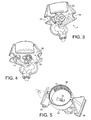
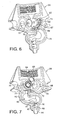
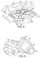
- FIGS 3 to 9 show the metering and mixing device 3 of the invention in detail according to a preferred embodiment.
- the device 3 is preferably in the form of a cap which closes the opening of the container in a sealed manner when the container is in the inverted position with its opening facing downwards.
- the cap has a tubular connecting portion 30 equipped with connecting means such as an internal screw thread 31 complementing connecting means 41 belonging to the container, also of the screw thread type for example. Inside the connecting portion there is an end surface and an inlet 32 situated through this end surface, for liquid to enter the device.
- the inverted position of the container is justified only if the container has an air inlet for equalizing the pressures in the container and does not therefore contract as it empties. If the opposite is true, such as in the case of a bag which contracts without air, the liquid can be metered when the container is in a position which is not necessarily the inverted one with the cap.
- the device 3 is preferably made up, amongst other things, of two half-shells 3A, 3B assembled with one another along a parting line P running more or less in the longitudinal direction of the ducts, particularly of the liquid duct and of the mixing chamber, circulating within the device.
- the construction in the form of two half-shells, namely a frontal part 3A and a rear other part 3B, makes it possible to simplify the device while at the same time defining the succession of ducts and chambers needed for metering, mixing, possibly frothing, and delivering the mixture.
- an air inlet into the container in order to compensate for the withdrawal of the liquid.
- Such an inlet may be provided either through the container itself, such as an opening in the bottom of the container, once this container is in the inverted position, or alternatively at least one air channel through the tubular connecting portion 30 of the device which communicates with the inlet to the container.
- the device comprises a built-in metering pump 6 for metering the liquid passing through the opening 32.
- the pump is preferably a gear pump defined by a chamber 60 equipped with bearings 61, 62, 63, 64 present at the bottom of each lateral surface 67, 68 of the chamber and able to guide two rotary elements 65, 66 cooperating in a geared fashion in order to form the moving metering elements of the pump in the chamber.
- the rotary element 65 is a "master" element equipped with a shaft 650 associated with a coupling means 651 able to engage with a complementary coupling means belonging to the base station 5 (described later on).
- a lip seal is preferably incorporated between the bearing 64 and the shaft 650 to seal the pump chamber with respect to the outside.
- the internal pressure when the pump is in motion helps with maintaining sealing by stressing the seal.
- the rotary element 66 is the "slave" element which is driven in the opposite direction of rotation by the master element.
- the rotary metering elements 65, 66 are driven in directions A, B as illustrated in Figures 8 and 10 in order to be able to meter the liquid through the chamber.
- the construction in the form of half-shells is such that the chamber is defined by the assembly of the two parts 3A, 3B.
- the chamber 60 may thus be defined as a hollow in the frontal part 3A with a bottom surface 67 defining one of the lateral surfaces.
- the other part encloses the chamber via a more or less flat surface portion 68, for example, comprising the bearing 64 that supports the drive shaft 650, which is extended backwards through a passage 78 through the shell part 3B.
- the liquid is thus metered through a liquid outlet duct 69 forming a reduction in section.
- the diameter is of the order of 0.2 to 4 mm, preferably 0.5 to 2 mm.
- the duct 69 allows fine control over the flow rate of liquid leaving the pump and makes it possible to form a relatively narrow flow of liquid, thus encouraging fine metering.
- the device comprises a duct 70 for supplying with diluent which intersects the liquid duct 69.
- the diluent is conveyed into the device through a diluent intake 71 located through the rear part 3B of the cap.
- This intake has the form of a connecting tube able to be forcibly fitted with sealing into a tubular coupling and diluent-supply part located on the base station 5.
- the diluent flow rate is controlled by a diluent pump situated in the base station 5.
- the diluent duct 70 ends in a restriction 72 beginning more or less upstream of the point where the liquid and diluent ducts 69, 70 meet and extending at least as far as that point and preferably beyond the meeting point.
- the restriction makes it possible to accelerate the diluent and this, using a venturi phenomenon, causes a pressure at the meeting point that is lower than or equal to the pressure of the liquid in the liquid outlet duct 69.
- this equilibrium or differential of pressures ensures that the diluent crosses the metering point and travels as far as the chamber without rising back up inside the liquid duct.
- the liquid pump stops while the diluent continues to pass through the device, for example towards the end of the drink preparation cycle in order to obtain the desired dilution of drink.
- the diluent is used to regularly rinse the device.
- the liquid for example a coffee or cocoa concentrate, is prevented from being contaminated in the container or the pump by diluent being sucked back through the duct 69.
- the restriction is thus sized to create a slight depression at the meeting point.
- the depression needs to be controlled so that it does not excessively lower the boiling point and cause the diluent to boil in the duct when hot drinks are being prepared.
- the restriction has a diameter of between 0.2 and 5 mm, more preferably between 0.5 and 2 mm.
- one and the same duct 73 transports the fluids.
- a widening of the duct is preferably designed to reduce the pressure drop and take account of the increase in volume of the fluids which combine once they have met at the meeting point.
- the widened duct 73 is extended into a mixing chamber 80 proper, in which the product is homogeneously mixed.
- the duct portion 73 and the chamber 80 could form one and the same duct or one and the same chamber without there necessarily being an abrupt change.
- An air intake embodied by an air duct 73 open to the open air is preferably provided when frothing of the liquid-diluent mixture is desired.
- the air duct may be positioned to intersect with the restriction. It is in this region that the venturi effect is felt and therefore that the reduction in pressure is at its maximum because of the acceleration of the fluids.
- the air duct may thus be positioned to intersect the duct portion 73 for example.
- the position of the air intake may vary and may also be sited in such a way as to lead to the diluent duct 70 or alternatively to the liquid duct 69.
- the air intake is positioned such that the air is sucked in by the effect of the diluent accelerating through the restriction.
- an air pump can be connected to the air intake.
- the air pump can be used for creating a positive pressure in the air intake which can force air to mix with the diluent stream.
- the restriction of the diluent duct is enough to draw a sufficient amount of air to create bubbles in the mixture but an air pump could prove to be helpful, in particular, at elevated diluent temperatures, where steam may start forming in the device thus resulting in no sufficient air to be able to be drawn.
- the air pump may also be used to send air in the mixing chamber at the end of the dispensing cycle in order to empty the chamber of the mixture and/or to dry off the mixing chamber for hygiene purpose.
- the air intake should also be connected to atmospheric pressure at the end of the dispensing cycle to ensure that the mixing chamber can properly empty. Such atmospheric pressure balance can be obtained by an active valve placed at the higher point in the air feed system.
- the mixing chamber 80 has a width of the order of at least five times, preferably at least ten or twenty times, the cross section of the duct portion 73 more or less at the exit from the meeting point.
- a broad chamber is preferable to a simple duct to encourage mixing and also to prevent any liquid from being sucked back into the venturi system when the device is at rest, as this could detract from the maintaining of good hygiene in the device.
- the chamber could be replaced by a duct of smaller cross section.
- the chamber also allows the mixture to be decelerated and therefore avoids the mixture being expelled too abruptly and possibly causing splashing as it is delivered.
- the chamber preferably has a bowed shape, or even preferably has the shape of a S so as to lengthen the path of the mixture and reduce the speed of the mixture.
- the chamber is connected mainly to a delivery duct 85 for delivering the mixture.
- a siphon passage 81 may also be provided in order to completely empty the chamber because of its bowed shape, after each delivered drink cycle.
- the duct preferably comprises elements 86, 87, 88 for breaking down the kinetic energy of the mixture in the duct.
- These elements may, for example, be several walls extending transversely to the duct and partially intersecting the flow of mixture and forcing this mixture to follow a sinuous path. These elements may also have a function of homogenizing the mixture before it is let out. Of course, other forms are possible for breaking the flow of the drink.
- the metering and mixing device also preferably comprises guide means allowing docking with the base station and, in particular, facilitating alignment of the diluent coupling and pump drive means.
- These guide means may, for example, be portions of surfaces 33, 34, 35, 36 through the device, for example, transversely to the parts 3A, 3B.
- the surfaces may, for example, be partially or completely cylindrical portions.
- the guide means also perform the function of supporting the weight of the package and ensure firm and stable docking. These means may of course adopt other highly varied shapes.
- the parts 3A, 3B are assembled by any appropriate means such as welding, bonding or the like.
- the two parts are laser welded.
- the laser welding may be computer controlled and has the advantage of welding the parts together without any movement, unlike vibration welding; this improves the compliance with dimensional tolerances and the precision of the welding.
- one of the parts may be formed in a material that is more absorbent of laser energy while the other part is made of a plastic transparent to laser energy.
- other welding techniques are possible without departing from the scope of the invention, for example vibration welding.
- a connecting joint 79 such as a weld, which partially or completely borders the ducts and chambers of the device.
- the joint is preferably perfectly sealed.
- a joint with non-welded regions may be provided in order to control the entry of air into the device.
- Figures 9 and 10 show a detailed depiction of the rotary elements 65, 66 of the liquid pump.
- the gearing elements each have teeth 652, 660 of complementing shapes, the cross section of which has a rounded shape towards the ends with an area of restricted cross section 661 at the base of each of the teeth.
- Such a rounded tooth geometry makes it possible to create a closed volumetric metering region 662 which does not experience compression and transports a volume of liquid that is constant for each revolution. This configuration has the effect of reducing the effects of compression on the metered liquid and this improves the efficiency of the pump and reduces the loads on the pump.
- the outermost portion 662 of each tooth is flattened with a radius greater than the radius of the sides 663 of each tooth.
- the flattening of the most extreme portions 664 allows the teeth to be brought closer to the surface of the pumping chamber, thus reducing clearance and improving sealing.
- the device can meter liquids over a wide range of viscosities.
- a valve to the liquid metering duct 69, or to the inlet 32, to prevent the risks of liquid leaks.
- the valve is configured to open under the thrust of the liquid exerted by the pump and to remain closed and sealed when the pump is switched off so as to prevent any liquid from leaking through the device.
- the container if not specifically designed to be collapsible, may require to be returned to a pressure of equilibrium with the external environment by the way of a venting means. If the container is not vented, it may collapse due to pressure reduction inside it and it can break.
- a venting means may be a valve such a duckbill valve and the like. Another way of venting the container may be to drive the pump for several turns in the direction opposite to the metering direction. A preferred venting way is described in relation to figures 15 to 17 as will be later explained in the present description.
- the system according to the invention also comprises a base station 5 forming the machine part, as opposed to the package 2.
- the base station comprises a technical area 50, generally internal and protected, at least in part, by a cover 55 and an interface area 51 directly accessible to the user.
- the interface area also offers control means 53 for controlling the delivery of a drink.
- the control means may be in the form of an electronic control panel ( Figures 1 and 2) or a lever ( Figure 11).
- the interface area 51 is configured to allow the docking of at least one package 2, via at least one docking station 52.
- Several docking stations may be provided, arranged in rows to each accept a package containing a different or the same food liquid, so that a varied choice of drink can be offered or alternatively in order to increase the system's serving capacity.
- a docking station comprises a diluent coupling means 520 and a means for coupling the drive to the metering pump 521.
- the means 520 may be a portion of a tube fitted with a non-return valve the diameter of which complements the diameter of the diluent intake 71 of the metering and mixing device so as to engage therewith. Assembly may be achieved using one or more seals.
- the coupling means 521 is, for example, a portion of a shaft ending in a head of smaller cross section and with surfaces that complement the internal surfaces of the coupling means 651 belonging to the metering and mixing device.
- the head may have a pointed shape of polygonal cross section or may be star shaped, for example, offering both speed of engagement and reliability in the rotational drive of the pump.
- the docking station may also comprise guide means 522, 523 that complement the guide means 33, 34 of the metering and mixing device. These means 522, 523 may be simple bars or fingers to accept the surfaces of the guide means in sliding. It goes without saying that the shape of the guide means 522, 523, 33, 34 may adopt numerous forms without departing from the scope of the invention. Thus, the guide means 522, 523 of the docking station may be hollow shapes and the guide means 33, 34 may be raised.
- the base station has a technical area 50 which combines the essential components for supplying the metering and mixing device 3 with diluent and for driving the liquid pump.
- the base station comprises a diluent supply source, such as a reservoir of drinking water 90 connected to a water pumping system 91.
- the water is then transported along pipes (not featured) as far as a water temperature control system 92.
- a system may be a heating system and/or a refrigeration system allowing the water to be raised or lowered to the desired temperature before it is introduced into the metering and mixing device 3.
- the base station possesses an electric motor 93 controlled by a controller 94.
- the electric motor 93 comprises a drive shaft 524 which passes through the docking panel 58.
- the system according to the invention offers the possibility of varying the metering of the liquid according to the requirements via a control panel 53 featured in the interface area, thanks to a selection of buttons each of which selects a specific drinks dispensing program.
- the liquid:diluent dilution ratio can vary by varying the speed at which the pump is driven. When the speed is slower, the diluent flow rate for its part being kept constant by the diluent pump system 91, the liquid:diluent ratio is thus reduced, leading to the delivering of a more dilute drink. Conversely, if the liquid pump speed is higher, the concentration of the drink can be increased.
- Another controllable parameter may be the volume of the drink by controlling the length of time for which the diluent pump system is activated and the length of time for which the liquid pump is driven.
- the controller 94 thus contains all the necessary drinks programs corresponding to the choice effected via each button on the control panel 53.
- the metering and mixing device or the container may also comprise a code that can be read by a reader associated with the base station 5.
- the code comprises information referring to the identity and/or the nature of the product and/or to parameters concerned with the activating of the diluent supply and/or liquid pump drive means.
- the code may, for example, be used to manage the flow rate of the liquid pump and/or of the diluent pump, contained in the base station, so as to control the liquid:diluent ratio.
- the code may also control the opening or closing of the air intake in order to obtain a frothy or non-frothy drink.
- the air intake or channel 74 can be placed to intersect the diluent duct 70. Therefore, it is placed before the intersection of the liquid stream and diluent stream.
- the problem with air channel placed after the intersection of the liquid and diluent ducts is that the air channel can become contaminated by diluted liquid which may cause bacterial growth. The problem is mostly caused by geometry and physical factors such as liquid surface tension, phase changes, etc.
- This air channel cannot be properly cleaned during a flushing cycle with a cleaning liquid (i.e., hot water) as the restriction causes a suction effect from the air channel to the mixing chamber that prevents the cleaning liquid from entering the air channel. Therefore, this new location ensures that no food liquid can enter the air channel.
- the diluent duct 70 and the liquid metering duct 69 are not directly positioned in intersection one another but meet with the mixing chamber 80.
- the diluent duct 70 is nevertheless positioned in such a way that its stream is directed toward the liquid stream, i.e., in the direction of the liquid outlet or slightly below.
- An air intake 74 is furthermore provided in the region of the restriction 72. The diluent speed is such in that region that air is sucked in the diluent stream before the stream meets the liquid stream. Such an arrangement reduces the risk of the air intake being contaminated with the diluted product coming in the air intake by accident.
- the device comprises a barrier valve 690 placed between the metering pump 65 and the mixing chamber 80.
- the barrier valve 690 is a non-return valve device that opens under the pump pressure to let liquid flow toward the mixing chamber but prevents a backflow, i.e. diluent from entering into the metering pump 65 and up to the container.
- the valve 690 acts as a hygienic and safety barrier so that the food liquid is not contaminated before reaching the mixing (dilution) chamber. Indeed, if diluent would contact the liquid, e.g. the beverage concentrate, portion(s) of the liquid would become diluted and would achieve a higher water activity that could be prone to constitute a media for microbial growth.
- the barrier valve 690 ensures that the liquid is not diluted in the pump nor upstream of the pump. Also, since it is virtually impossible to guarantee total tightness in particular for low viscosity liquids, the valve 690 that is added e.g. in the liquid metering conduit downstream of the pump prevents liquid from dripping in the mixing chamber or at the intersection area 72. Since traces of water cannot be totally removed or dried in the intersection area 72 and the mixing chamber, if liquid drips from the pump to these areas, the diluent could contaminate the liquid therefore causing a potentially favourable ground for bacterial growth after several hours of inactivity. The valve also prevents this issue by stopping the liquid from dripping during inactivity of the device.
- the barrier valve 690 also enables to reduce the rinsing cycle.
- the amount of rinsing fluid, i.e., hot water that is necessary to be flushed after each liquid metering can be advantageously reduced since the valve closes automatically the liquid duct 69 when the metering means is stopped. Therefore, the liquid immediately stops being dispensed in the chamber. Therefore, rinsing with hot diluent can be kept as minimal as possible, be preferably integrated as a part of the final beverage dispensing cycle and can be so much less perceptible for the user.
- the valve 690 can be any sort of non-return valve.
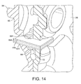
- the valve 690 can be as illustrated in the embodiment of figure 14, a elastomeric valve 690 injected in a single piece, for instance, an injected silicone valve. In this case, the valve 690 can be maintained in place along its edges being tightly inserted in a portion of slit provided in each half shell 3a, 3b.
- the valve 690 comprises an elastomeric or silicone slit valve member or layer 691 maintained transversally in the liquid duct 69 by two rigid plies such as two metal plates 692, 693.
- the valve 690 can be inserted through slots provided through the two half-shells 3A, 3B.
- the slit valve member is configured so that the slits open downwardly when a fluid pressure has built up upstream the valve as a result of the pump being activated in the pump chamber 60 (pump members not shown). As soon as the pump is stopped, the valve is resilient enough to close off the outlet.
- This aspect of the invention deals with the problem that, when dispensing a liquid from an essentially closed container, the pressure in the container will decrease, thus creating a vacuum which can be detrimental to the dispensing action.
- this aspect of the present invention proposes a particularly advantageous solution for compensating the liquid volume dispensed from a sealed container, such that the pressure inside the essentially sealed container is re-balanced when dispensing liquid therefrom.
- the air compensation flow does not necessarily have to take place at the same time of the dispensing action.
- the pressure drop caused by a short single dispensing action usually is not a problem as long as this pressure drop does not accumulate during the course of several dispensing actions. As will be explained later on, allowing a short reduction of the pressure during dispensing and compensating later on can even have advantages.
- this aspect of the invention can also find application without mixing the dispensed liquid with a diluent as described with reference to figures 1 to 14 but may also apply to a simply metering and dispensing a liquid without added diluent (e.g., in the application to the dispense of a "ready-to-drink" beverage for instance).
- control means are provided which control the draining of liquid from a container to a dispensing outlet.
- rotary metering means (a gear pump being only one example thereof) are used for controlling the metering, i.e. the flow of a liquid (e.g. a base liquid) from the container e.g. into a mixing chamber.
- a liquid e.g. a base liquid
- the compensatory flow of air through the cap is taking place in a controlled manner, e.g. especially it can be turned off and on e.g. by control means.
- the compensatory flow of air into the container can be controlled regarding the timing (i.e. the time when it takes place)and/or the volume of air which is allowed to enter the container.
- control means can e.g. be electronic control means which also control the metered draining from the liquid from the container to the liquid outlet (69) and in the mixing chamber.
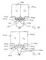
- Figure 15 shows the cap 3 to be attached to an opening of a container (bottle etc.). Again, reference 3a designates the front shell and reference 3b designates the rear shell of the dispensing cap device 3.
- a piston rod 1000 can protrude through an opening 1001 made in the centre part of the rear shell 3b.
- the piston rod 1000 is the main element of a valve which is controlled to allow or prevent the flow of air from the outside into the cap 3 and then into the attached container.
- Other actively controlled valve arrangements can equally be used in connection with the present invention.
- the piston rod 1000 can be transferred between a closed position (left side of Figure 17) inhibiting air flow and an open position (right side of Figure 17) preventing the flow of air from the outside into the cap and then into the attached container.
- a conical seat 1004 of the piston rod 1000 tightly seals the opening 1001 in the rear shell 3b.
- no air from the outside can enter a air flow channel 1005.
- the air flow channel 1005 is provided between the rear shell 3b and the front shell 3a of the cap dispensing device 3.
- the air flow channel 1005 can selectively provide for a fluid connection between the ambience (i.e. the exterior of the cap dispensing device 3) and the interior of a container attached to the cap dispensing device 3.
- the air flow channel 1005 is separated from the channel for dispensing the liquid from a container attached to the dispensing cap 3.
- the piston rod 1000 is provided with a spring biasing element 1003, which can have a spring-elastic effect due to its shape and/or its constituting material (e.g. it can be made from silicon or other rubber-elastic materials).
- This spring biasing element 1003 secures the piston rod 1000 in the closed position in case no external forces are applied. Again, in this spring-biased closed position of the piston rod there is no fluid communication between the exterior of the cap device 3 and the air flow channel 1005 leading to the interior of an attached container.
- Guiding means 1002 such as for example three guiding longitudinal lips can be provided at the edge of the opening to prevent the piston rod 1000 from rotating through the opening 1001 in the rear shell 3b.
- Control means can now control an actuator to actively transfer the piston rod 1000 from the closed position to the open position as shown in the right figure of Figure 17.
- the piston rod 1000 In the open position the piston rod 1000 is actively pushed by an actuator to the right against the spring biasing force of the spring biasing member 1003.
- the conical seat 1004 of the piston rod is leaving its sealed seat in the opening 1001 in the rear shell 3b, such that a clearance occurs between a cylindrical element 1006 of the piston rod and the opening 1001 in the rear shell 3b, as the diameter of the cylindrical element 1006 of the piston rod 1000 is a little smaller than the inner diameter of the opening 1001.
- This clearance now constitutes a fluid (air) flow communication channel between the exterior of the cap device 3 and the air flow channel 1005 such that in the position as shown in Figure 17, right hand side, air as indicated by the arrow can flow from the outside, through the clearance between the cylindrical portion 1006 and the opening 1001 in the rear shell 3b into the air flow channel 1005 of the cap device 3 and thus into the interior of a container attached to the cap dispensing device 3.
- the air flow channel 1005 enters the interior of the attached container at a position which is different to the position at which the base liquid is allowed to leave the container.
- the transfer from the closed state to the open state of the piston rod 1000 is actively controlled, e.g. by a solenoid controlled by an Electronic Control Unit (ECU).
- ECU Electronic Control Unit
- the piston rod will automatically return to the closed position as shown in the left hand on figure 17 due to the spring biasing force of the spring biasing element 1003. In other words, without an active control the compensatory air flow will stop.
- air valve comprising the piston rod or comparable means can alternatively be biased in the open position and then be actively transferred into the closed position.
- both states (open/close) and the transfer between these states can be actively controlled by an actuator.
- control means are designed such that the compensatory flow of air into the container is only allowed during periods in which no liquid is allowed to leave the container to the dispensing outlet.
- This has the advantage that no air bubbles generated by the compensatory air flow are re-sucked into the dispensing cap 3, in particular, in the liquid metering means, which can, in turn, generate problems with regard to a reliable metering and the reliable function of the rotary metering means (pump).
- the compensatory air flow is particularly advantageous in case a non-collapsible container or a container with limited ability to collapse (e.g., semi-rigid blow-moulded plastic) is used.
- a decrease of pressure will occur in the container thus forcing the walls of the container inwardly to the difference of the pressure between the external (atmospheric) pressure and the decreased internal pressure.
- the negative pressure in the container reaches a certain value, the liquid can no longer be pumped by the metering device.
- the invention provides for means for balancing the internal pressure of the container such that the container can keep or recover its form after dosing a certain volume of liquid from the container. Therefore, liquid can be dosed at pressure close to or at the atmospheric pressure, therefore, no longer forcing on the metering device.
- the turning off and on of the compensatory air flow is actively controlled e.g. by an actuator.
- this turning off/on of the compensatory air flow into the container is independent from the liquid dispensing action.
- the independent control of the compensatory air flow vis-à-vis the draining of the liquid give the possibility that the periods when the compensatory air flow is allowed can be made separate from the period during which liquid is drained from the container.
- an air compensation valve is proposed that is actively controlled and especially controlled independently from the liquid draining action.
- the air compensation valve can be actively actuated thus it is opened only during periods during which the action of the dosing pump is stopped or nearly stopped. As a result, air entering the container can no longer be re-drawn into the dispensing device.
- the air compensation device is based on a valve member (piston rod) that it is spring biased and comprises an actively controlled portion that can be controlled by the external control device comprising an actuator (e.g. a solenoid).
- the venting device can be integrated into the cap and is thus disposable together with the container, while the control device and the actuator can be a permanent part of the machine.
- the product is dosed from the dispensing cap device while the air compensation valve member stays closed.
- the pump is rotated to deliver (meter) the proper amount of liquid depending on the beverage to deliver and mix it with a diluent.
- the container slightly deforms since the pressure inside the container will be lowered.
- the air compensation valve will be opened actively by the controller that commands e.g. a solenoid. Air will so enter the container creating bubbling in the container. However, since the metering device is stopped, no air will be forced in the metering device.
- the air compensation (venting) action can be controlled depending on the amount of liquid dispensed from the container. Therefore the amount of air that is drawn in order to compensate for the amount of liquids can be calculated properly.
- an electronic control can have a simple control function that provides a correlation between the dispense liquid volume and the venting time, i.e. the time during which compensatory air is allowed to flow into the container.
- the air compensation valve will remain open during a defined time period that is a calculated function of the volume of liquid which has been dispensed in a previous step.
- venting device assists in preventing diluent from being drawn in the liquid metering duct or liquid outlet by balancing the pressure, i.e. removing the negative pressure in the container.
- the venting device acts together with the barrier valve 690 to ensure that no diluent, e.g. water, can actually enter into the metering device and above in the container which otherwise would cause a source of potential microbial contamination and growth.
- the device of the invention is a device for metering at least a first and second liquids and mixing the two liquids with a diluent to prepare a food product.
- the device is able to be connected to at least two compartments 1100, 1101.
- Each compartment 1100, 1101 can contain one of the first or second liquids to be mixed.
- the at least one diluent duct can be positioned relatively to the liquid metering ducts 1102, 1103 for the diluent to intersect the liquid stream before or at the mixing chamber 1106.
- a first and a second liquid pump 1107, 1108 are provided, which are part of the device, to meter respectively the first and second liquids in the first and second liquid ducts.
- the device can comprise active or passive means 1109, 1110 for accelerating the speed of the diluent at the diluent inlet, in the region where the diluent meets with the first and second liquids.
- the accelerating means are regions with restricted cross-sections.
- the diluent duct 1104 is common and centrally positioned relative to the two liquid metering means.
- the diluent flow is divided in two portions to pass through two separate restrictions 1109, 1110 to intersect the metered liquids at two separate intersection points.
- two separate diluent ducts 1104, 1105 are provided; one for each liquid metering means 1107, 1108.
- Each diluent duct is able to accelerate the diluent flow through restrictions 1109, 1110.
- the device may also comprise several liquid pumps each comprising a liquid duct which meets one or more diluent ducts.
- the advantage is then that of being able to mix several different liquids with flow rate ratios determined by each of the pumps.
- the pumps may be arranged either in the same plane or in a parallel plane.
- One or more containers 1100, 1101 may be provided. If one container is provided, the container may comprise several chambers or compartments containing different liquids, each chamber communicating with its corresponding pump. The pumps may communicate to a common mixing chamber so that mixing occurs in the common mixing chamber. Several separate containers (each having a liquid compartment) may be provided that are attached to a common device as mentioned.
- the preparation of a drink may also comprise two or more liquid components which have to be kept separate for reasons of stability, shelf life and/or beverage customization.
- the liquid components may comprise a base of concentrate on the one hand and a flavouring, distillate or aroma on the other, thus metered by different pumps to reconstitute a flavoured drink or a drink with a better flavour.
- the pumps are set up to deliver the liquid components in the mixing chamber at a predetermined ratio of the first and second liquid components.
- a first component base of concentrate can be: coffee or tea.
- a second component can be: a coffee or tea distillate or aroma or another additive. In that mode, the coffee or tea base concentrate can be substantially free of coffee aroma.
- the aroma can be stripped off and then collect during coffee or tea concentration processing.
- each diluent duct can meet with each liquid duct at a different intersection point (see Figures 18 and 19).
- a means for accelerating the flow of diluent 1109, 1110 can be placed before each intersection point with the first and second liquids.
- the mixing chamber can be placed downstream of the two different intersection points.
- the invention also extends to the field of the preparation of non-food products.
- the invention may be used in the field of the dispensing of products which come in the form of liquids that can be diluted, such as washing powders, soaps, detergents or other similar products. Therefore, the invention also relates to a device for dispensing a non-food and non-nutritional liquid from a container comprising the above described features and advantages.
Priority Applications (14)
| Application Number | Priority Date | Filing Date | Title |
|---|---|---|---|
| EP06000320A EP1806314A1 (de) | 2006-01-09 | 2006-01-09 | Vorrichtung und Verfahren mit gesteuertem Lufteinlass zur abgabe eines Getränks |
| BRPI0706393-8A BRPI0706393A2 (pt) | 2006-01-09 | 2007-01-05 | Dispositivo para dispensação de uma bebida com uma entrada de ar controlada, e um método para a mesma |
| KR1020087018762A KR101318074B1 (ko) | 2006-01-09 | 2007-01-05 | 공기 유입이 제어된 상태로 음료를 분배하는 장치 및 그방법 |
| EP07703663A EP1979263A1 (de) | 2006-01-09 | 2007-01-05 | Vorrichtung zur ausgabe eines getränks mit gesteuertem lufteinlass und verfahren dafür |
| NZ569662A NZ569662A (en) | 2006-01-09 | 2007-01-05 | Device for dispensing a beverage with a controlled air inlet, and method thereof |
| AU2007204348A AU2007204348B2 (en) | 2006-01-09 | 2007-01-05 | Device for dispensing a beverage with a controlled air inlet, and method thereof |
| RU2008132823/12A RU2426687C2 (ru) | 2006-01-09 | 2007-01-05 | Устройство для выдачи напитка с воздушным впускным отверстием и способом управления им |
| CN200780006178.5A CN101389564B (zh) | 2006-01-09 | 2007-01-05 | 用于分配饮料的具有受控的进气口的设备及方法 |
| MX2008008682A MX2008008682A (es) | 2006-01-09 | 2007-01-05 | Dispositivo para dispensar una bebida con una entrada controlada de aire y metodo del mismo. |
| CA002636366A CA2636366A1 (en) | 2006-01-09 | 2007-01-05 | Device for dispensing a beverage with a controlled air inlet, and method thereof |
| PCT/EP2007/050105 WO2007080150A1 (en) | 2006-01-09 | 2007-01-05 | Device for dispensing a beverage with a controlled air inlet, and method thereof |
| JP2008549864A JP5249046B2 (ja) | 2006-01-09 | 2007-01-05 | 制御式の空気導入口を備える飲料送出装置およびその方法 |
| US12/160,276 US8371477B2 (en) | 2006-01-09 | 2007-01-05 | Device for dispensing a beverage with a controlled air inlet, and method thereof |
| TW096100716A TWI436752B (zh) | 2006-01-09 | 2007-01-08 | 用於自一容器施配一液體之裝置及方法 |
Applications Claiming Priority (1)
| Application Number | Priority Date | Filing Date | Title |
|---|---|---|---|
| EP06000320A EP1806314A1 (de) | 2006-01-09 | 2006-01-09 | Vorrichtung und Verfahren mit gesteuertem Lufteinlass zur abgabe eines Getränks |
Publications (1)
| Publication Number | Publication Date |
|---|---|
| EP1806314A1 true EP1806314A1 (de) | 2007-07-11 |
Family
ID=36593992
Family Applications (2)
| Application Number | Title | Priority Date | Filing Date |
|---|---|---|---|
| EP06000320A Withdrawn EP1806314A1 (de) | 2006-01-09 | 2006-01-09 | Vorrichtung und Verfahren mit gesteuertem Lufteinlass zur abgabe eines Getränks |
| EP07703663A Withdrawn EP1979263A1 (de) | 2006-01-09 | 2007-01-05 | Vorrichtung zur ausgabe eines getränks mit gesteuertem lufteinlass und verfahren dafür |
Family Applications After (1)
| Application Number | Title | Priority Date | Filing Date |
|---|---|---|---|
| EP07703663A Withdrawn EP1979263A1 (de) | 2006-01-09 | 2007-01-05 | Vorrichtung zur ausgabe eines getränks mit gesteuertem lufteinlass und verfahren dafür |
Country Status (13)
| Country | Link |
|---|---|
| US (1) | US8371477B2 (de) |
| EP (2) | EP1806314A1 (de) |
| JP (1) | JP5249046B2 (de) |
| KR (1) | KR101318074B1 (de) |
| CN (1) | CN101389564B (de) |
| AU (1) | AU2007204348B2 (de) |
| BR (1) | BRPI0706393A2 (de) |
| CA (1) | CA2636366A1 (de) |
| MX (1) | MX2008008682A (de) |
| NZ (1) | NZ569662A (de) |
| RU (1) | RU2426687C2 (de) |
| TW (1) | TWI436752B (de) |
| WO (1) | WO2007080150A1 (de) |
Cited By (14)
| Publication number | Priority date | Publication date | Assignee | Title |
|---|---|---|---|---|
| GB2449070A (en) * | 2007-05-08 | 2008-11-12 | Easy Cocktails Ltd | Cocktail dispenser |
| EP2017221A1 (de) * | 2007-07-19 | 2009-01-21 | Nestec, Ltd. | Vorrichtung zur Abgabe einer Flüssigkeit |
| WO2011037464A1 (en) | 2009-09-24 | 2011-03-31 | Sara Lee/De N.V. | Beverage cartridge |
| WO2011076520A1 (en) * | 2009-12-22 | 2011-06-30 | Unilever Plc | Beverage dispenser with water cooler and concentrate adding device |
| WO2011076521A1 (en) * | 2009-12-22 | 2011-06-30 | Unilever Plc | Beverage dispenser with water cooler |
| WO2011049446A3 (en) * | 2009-10-20 | 2011-09-01 | Sara Lee/De N.V. | Fluid packaging container |
| EP2596727A3 (de) * | 2011-10-07 | 2014-11-26 | Wmf Württembergische Metallwarenfabrik Ag | Luftpumpe zum Dosieren von Luft in Milchschäumsystemen |
| EP2814772A4 (de) * | 2012-02-13 | 2015-11-18 | Ecolab Usa Inc | Andockstation für flüssigkeitsbehälter |
| WO2017121802A1 (de) * | 2016-01-12 | 2017-07-20 | Freezio Ag | Kartuschenaufnahme, kartuschensystem, getränkezubereitungsmaschine und verfahren zur herstellung eines getränks |
| EP2625017B1 (de) * | 2010-10-08 | 2018-09-26 | 3M Innovative Properties Company | Verfahren und vorrichtung zur ausgabe von flüssigkeiten aus einem an eine integrierte pumpenkappe gekoppelten behälter |
| US10368686B2 (en) | 2014-01-03 | 2019-08-06 | Koninklijke Douwe Egberts B.V. | Method for taking into use an exchangeable supply pack in a beverage dispensing machine and system comprising an exchangeable supply pack and computer program product |
| EP3214981B1 (de) * | 2014-11-06 | 2020-07-22 | Société des Produits Nestlé S.A. | System zur zubereitung von speisen oder getränken aus einer verpackung |
| US11261022B2 (en) | 2016-07-07 | 2022-03-01 | Freezio Ag | Single-portion package, use, and preparation machine |
| US11607073B2 (en) | 2017-06-26 | 2023-03-21 | Freezio Ag | Device for producing a beverage |
Families Citing this family (29)
| Publication number | Priority date | Publication date | Assignee | Title |
|---|---|---|---|---|
| JP4824105B2 (ja) * | 2009-08-11 | 2011-11-30 | 株式会社フジヤマ | 液体貯留装置 |
| US8768524B2 (en) | 2010-06-04 | 2014-07-01 | Pepsico, Inc. | System and method for rapid reconfiguration of post-mix beverage dispenser |
| DE202011002208U1 (de) | 2011-02-01 | 2012-01-13 | Bürkert Werke GmbH | Dosiereinheit |
| WO2013165585A1 (en) | 2012-05-04 | 2013-11-07 | Ecolab Usa Inc. | An apparatus, method and system for standardizing hand care |
| US9027790B2 (en) * | 2012-10-19 | 2015-05-12 | Gojo Industries, Inc. | Dispensers for diluting a concentrated liquid and dispensing the diluted concentrate |
| ITTO20120930A1 (it) * | 2012-10-23 | 2014-04-24 | Bruno Pirone | Dispositivo di additivazione per bevande e metodo associato. |
| US20140276422A1 (en) * | 2013-03-14 | 2014-09-18 | Medrad, Inc. | Bulk fluid source injector systems |
| DE102013104339A1 (de) * | 2013-04-29 | 2014-10-30 | Melitta Professional Coffee Solutions GmbH & Co. KG | Verfahren und Vorrichtung zur Erzeugung von Milchprodukten, insbesondere Milchschaum |
| EP2798988B1 (de) | 2013-04-29 | 2016-05-18 | Melitta Professional Coffee Solutions GmbH & Co., KG | Vorrichtung zum Erzeugen eines Milchschaumes |
| WO2015102488A1 (en) | 2014-01-03 | 2015-07-09 | Koninklijke Douwe Egberts B.V. | System for preparing beverage consumptions |
| EP3089639B1 (de) * | 2014-01-03 | 2018-07-11 | Koninklijke Douwe Egberts B.V. | Austauschbare versorgungspackung für einen getränkeautomaten, dosierer, pumpenanordnung und verfahren zur herstellung |
| US9771253B2 (en) * | 2014-04-21 | 2017-09-26 | The Coca-Cola Company | Beverage dispenser with component wash system |
| CN106455859B (zh) * | 2014-06-25 | 2020-05-19 | 雀巢产品有限公司 | 泵送和发泡设备 |
| KR20170022988A (ko) * | 2014-06-25 | 2017-03-02 | 네스텍 소시에테아노님 | 일회용 발포 장치 |
| NL2013984B1 (en) * | 2014-12-15 | 2016-10-11 | Douwe Egberts Bv | Dosing pump device for dosing metered amounts of a liquid product. |
| WO2016096913A1 (en) | 2014-12-15 | 2016-06-23 | Koninklijke Douwe Egberts B.V. | System for preparing beverage consumptions |
| US10512276B2 (en) * | 2015-02-09 | 2019-12-24 | Fbd Partnership, Lp | Multi-flavor food and/or beverage dispenser |
| NL2014993B1 (en) * | 2015-06-19 | 2017-01-23 | Siseb Systems B V | Single-use container for a single portion substance. |
| US10194678B2 (en) | 2015-09-09 | 2019-02-05 | Taylor Commercial Foodservice Inc. | Frozen beverage machine valving |
| EP3716823B1 (de) * | 2017-11-27 | 2022-02-16 | Freezio AG | Kartuschenaufnahme, kartuschensystem, getränkezubereitungsmaschine und verfahren zur herstellung eines getränks |
| GB2576779A (en) * | 2018-09-03 | 2020-03-04 | Quantex Patents Ltd | Dispenser systems, in-line dispenser assemblies, methods of using and cleaning same |
| USD918339S1 (en) | 2018-09-12 | 2021-05-04 | 3M Innovative Properties Company | Liquid delivery system cup |
| USD898868S1 (en) | 2018-09-12 | 2020-10-13 | 3M Innovative Properties Company | Liquid delivery system lid |
| USD919045S1 (en) | 2018-09-12 | 2021-05-11 | 3M Innovative Properties Company | Liquid delivery system coupler |
| US10864538B2 (en) | 2019-03-13 | 2020-12-15 | Chapin Manufacturing, Inc. | Dual chamber backpack sprayer |
| EP3795534A1 (de) * | 2019-09-18 | 2021-03-24 | Brita GmbH | Verfahren zum zapfen karbonisierten wassers |
| US20210267355A1 (en) | 2020-02-27 | 2021-09-02 | Jason Litner | Personal cosmetic dispenser |
| US11649152B2 (en) * | 2020-06-25 | 2023-05-16 | TechFit Inc. | Beverage infusion apparatus and method for infusing gas into a beverage |
| US11549244B2 (en) * | 2020-11-24 | 2023-01-10 | Renande Alteon | Multifunctional smart faucet |
Citations (12)
| Publication number | Priority date | Publication date | Assignee | Title |
|---|---|---|---|---|
| US4096971A (en) * | 1975-03-21 | 1978-06-27 | Dagma Gmbh & Co. Deutsche Automaten- Und Getranke - Maschinen | Method of and apparatus for dispensing self-conserving liquids |
| US4364493A (en) * | 1979-08-15 | 1982-12-21 | Arthur Guinness Son And Company (Park Royal) Limited | Beverage dispensing system |
| EP0159259A1 (de) * | 1984-04-03 | 1985-10-23 | Societe De Developpements Et D'innovations Des Marches Agricoles Et Alimentaires - Sodima- Union Des Cooperatives Agricoles | Vorrichtung zur automatisierten portionsweisen Abgabe von nach Wunsch aromatisiertem Trinkjoghurt |
| WO1992011082A1 (en) * | 1990-12-17 | 1992-07-09 | Imi Cornelius Inc. | Constant ratio post-mix beverage dispensing valve |
| US5305923A (en) | 1990-06-06 | 1994-04-26 | The Coca-Cola Company | Postmix beverage dispensing system |
| US5615801A (en) | 1990-06-06 | 1997-04-01 | The Coca-Cola Company | Juice concentrate package for postmix dispenser |
| US5842603A (en) | 1990-06-06 | 1998-12-01 | The Coca-Cola Company | Postmix juice dispenser |
| US6092693A (en) * | 1994-06-16 | 2000-07-25 | Powell; Anthony | Device for dispensing liquids in a desired ratio |
| WO2001021292A1 (en) | 1999-09-24 | 2001-03-29 | Asept International Ab | Method and device for production of beverages |
| US6223791B1 (en) * | 1999-10-21 | 2001-05-01 | 3M Innovative Properties Company | Gravity feed fluid dispensing valve |
| US20010004081A1 (en) * | 1999-12-16 | 2001-06-21 | Robert Tansley | Bottled liquid dispensers |
| US6568565B1 (en) | 2001-04-04 | 2003-05-27 | Lancer Partnership, Ltd. | Method and apparatus for dispensing product |
Family Cites Families (15)
| Publication number | Priority date | Publication date | Assignee | Title |
|---|---|---|---|---|
| US2939611A (en) * | 1958-02-10 | 1960-06-07 | Knapp Monarch Co | Self-venting container |
| US3994423A (en) * | 1973-06-28 | 1976-11-30 | American Hospital Supply Corporation | Drop dispensing apparatus for laboratory reagents |
| US4194650B2 (en) * | 1977-02-14 | 1989-01-31 | Liquid mixing and aerating system | |
| US4247018A (en) * | 1979-12-14 | 1981-01-27 | The Coca-Cola Company | Non-pressurized fluid transfer system |
| CN85102860A (zh) * | 1985-04-17 | 1986-10-15 | 发展及革新公司 | 酸奶酪与可任选的果味原料按个人用量需要进行自动配置的装置 |
| US5154319A (en) * | 1989-09-22 | 1992-10-13 | The Coca-Cola Company | Apparatus for the dispensing of liquids in measured amounts |
| US5133482A (en) * | 1990-11-28 | 1992-07-28 | Ebtech, Inc. | Syrup dispenser valve assembly |
| JP2540692B2 (ja) * | 1992-05-27 | 1996-10-09 | 前澤給装工業株式会社 | 予蓄タンクを備えた給水装置 |
| US5381926A (en) * | 1992-06-05 | 1995-01-17 | The Coca-Cola Company | Beverage dispensing value and method |
| JP2561505Y2 (ja) * | 1993-05-19 | 1998-01-28 | ホシザキ電機株式会社 | 液体注出装置における液体容器の接続構造 |
| JP3344451B2 (ja) * | 1995-12-14 | 2002-11-11 | 株式会社タツノ・メカトロニクス | 車載用オイル供給装置 |
| JPH10245099A (ja) * | 1997-03-06 | 1998-09-14 | Fuji Electric Co Ltd | 飲料ディスペンサ |
| ATE275091T1 (de) * | 2001-01-24 | 2004-09-15 | Lindberg & Jensen Aps | Dosiervorrichtung für einen behälter |
| DE102004009643A1 (de) * | 2004-02-27 | 2005-09-15 | Fafnir Gmbh | Lüftungsmast-Überwachungssystem für Tankstellen |
| AU2005262036B2 (en) * | 2004-07-09 | 2011-11-03 | Smixin Sa | System and device for preparing and delivering food products from a mixture made up of a food liquid and a diluent |
-
2006
- 2006-01-09 EP EP06000320A patent/EP1806314A1/de not_active Withdrawn
-
2007
- 2007-01-05 WO PCT/EP2007/050105 patent/WO2007080150A1/en active Application Filing
- 2007-01-05 KR KR1020087018762A patent/KR101318074B1/ko not_active IP Right Cessation
- 2007-01-05 CN CN200780006178.5A patent/CN101389564B/zh not_active Expired - Fee Related
- 2007-01-05 AU AU2007204348A patent/AU2007204348B2/en not_active Ceased
- 2007-01-05 BR BRPI0706393-8A patent/BRPI0706393A2/pt not_active IP Right Cessation
- 2007-01-05 CA CA002636366A patent/CA2636366A1/en not_active Abandoned
- 2007-01-05 JP JP2008549864A patent/JP5249046B2/ja not_active Expired - Fee Related
- 2007-01-05 EP EP07703663A patent/EP1979263A1/de not_active Withdrawn
- 2007-01-05 US US12/160,276 patent/US8371477B2/en not_active Expired - Fee Related
- 2007-01-05 RU RU2008132823/12A patent/RU2426687C2/ru not_active IP Right Cessation
- 2007-01-05 MX MX2008008682A patent/MX2008008682A/es active IP Right Grant
- 2007-01-05 NZ NZ569662A patent/NZ569662A/en not_active IP Right Cessation
- 2007-01-08 TW TW096100716A patent/TWI436752B/zh not_active IP Right Cessation
Patent Citations (12)
| Publication number | Priority date | Publication date | Assignee | Title |
|---|---|---|---|---|
| US4096971A (en) * | 1975-03-21 | 1978-06-27 | Dagma Gmbh & Co. Deutsche Automaten- Und Getranke - Maschinen | Method of and apparatus for dispensing self-conserving liquids |
| US4364493A (en) * | 1979-08-15 | 1982-12-21 | Arthur Guinness Son And Company (Park Royal) Limited | Beverage dispensing system |
| EP0159259A1 (de) * | 1984-04-03 | 1985-10-23 | Societe De Developpements Et D'innovations Des Marches Agricoles Et Alimentaires - Sodima- Union Des Cooperatives Agricoles | Vorrichtung zur automatisierten portionsweisen Abgabe von nach Wunsch aromatisiertem Trinkjoghurt |
| US5305923A (en) | 1990-06-06 | 1994-04-26 | The Coca-Cola Company | Postmix beverage dispensing system |
| US5615801A (en) | 1990-06-06 | 1997-04-01 | The Coca-Cola Company | Juice concentrate package for postmix dispenser |
| US5842603A (en) | 1990-06-06 | 1998-12-01 | The Coca-Cola Company | Postmix juice dispenser |
| WO1992011082A1 (en) * | 1990-12-17 | 1992-07-09 | Imi Cornelius Inc. | Constant ratio post-mix beverage dispensing valve |
| US6092693A (en) * | 1994-06-16 | 2000-07-25 | Powell; Anthony | Device for dispensing liquids in a desired ratio |
| WO2001021292A1 (en) | 1999-09-24 | 2001-03-29 | Asept International Ab | Method and device for production of beverages |
| US6223791B1 (en) * | 1999-10-21 | 2001-05-01 | 3M Innovative Properties Company | Gravity feed fluid dispensing valve |
| US20010004081A1 (en) * | 1999-12-16 | 2001-06-21 | Robert Tansley | Bottled liquid dispensers |
| US6568565B1 (en) | 2001-04-04 | 2003-05-27 | Lancer Partnership, Ltd. | Method and apparatus for dispensing product |
Cited By (75)
| Publication number | Priority date | Publication date | Assignee | Title |
|---|---|---|---|---|
| GB2449070A (en) * | 2007-05-08 | 2008-11-12 | Easy Cocktails Ltd | Cocktail dispenser |
| EP2017221A1 (de) * | 2007-07-19 | 2009-01-21 | Nestec, Ltd. | Vorrichtung zur Abgabe einer Flüssigkeit |
| WO2009010453A2 (en) * | 2007-07-19 | 2009-01-22 | Nestec S.A. | Device for dispensing a liquid |
| WO2009010453A3 (en) * | 2007-07-19 | 2009-03-12 | Nestec Sa | Device for dispensing a liquid |
| AU2016201186B2 (en) * | 2009-09-24 | 2017-12-14 | Koninklijke Douwe Egberts B.V. | Beverage cartridge |
| CN102574672A (zh) * | 2009-09-24 | 2012-07-11 | 莎莉/De有限公司 | 饮料盒 |
| WO2011037464A1 (en) | 2009-09-24 | 2011-03-31 | Sara Lee/De N.V. | Beverage cartridge |
| US9883767B2 (en) | 2009-09-24 | 2018-02-06 | Koninklijke Douwe Egberts B.V. | Beverage cartridge |
| RU2544134C2 (ru) * | 2009-09-24 | 2015-03-10 | Конинклейке Дауве Егбертс Б.В. | Картридж для напитка |
| US9648980B2 (en) | 2009-09-24 | 2017-05-16 | Koninklijke Douwe Egberts B.V. | Beverage cartridge |
| GB2486840A (en) * | 2009-09-24 | 2012-06-27 | Sara Lee De Bv | Beverage cartridge |
| CN105174183B (zh) * | 2009-09-24 | 2019-02-01 | 皇家戴维艾格伯茨有限公司 | 用在饮料分配系统中的饮料盒 |
| RU2586059C2 (ru) * | 2009-09-24 | 2016-06-10 | Конинклейке Дауве Егбертс Б.В. | Система выдачи напитка |
| GB2486840B (en) * | 2009-09-24 | 2016-01-27 | Koninkl Douwe Egberts Bv | Beverage cartridge |
| JP2013505769A (ja) * | 2009-09-24 | 2013-02-21 | コーニンクラケ ダウ エグバート ビー.ブイ. | 飲料カートリッジ |
| CN105174183A (zh) * | 2009-09-24 | 2015-12-23 | 皇家戴维艾格伯茨有限公司 | 饮料盒和饮料分配系统 |
| EP2653440A1 (de) | 2009-09-24 | 2013-10-23 | Koninklijke Douwe Egberts B.V. | Getränkepatrone |
| CN102574672B (zh) * | 2009-09-24 | 2015-11-25 | 皇家戴维艾格伯茨有限公司 | 饮料盒 |
| AU2010298802B2 (en) * | 2009-09-24 | 2015-11-19 | Koninklijke Douwe Egberts B.V. | Beverage cartridge |
| WO2011049446A3 (en) * | 2009-10-20 | 2011-09-01 | Sara Lee/De N.V. | Fluid packaging container |
| JP2013508232A (ja) * | 2009-10-20 | 2013-03-07 | コーニンクラケ ダウ エグバート ビー.ブイ. | 流体包装容器 |
| US9399570B2 (en) | 2009-12-22 | 2016-07-26 | Conopco, Inc. | Beverage dispenser with water cooler and concentrate adding device |
| CN102762485A (zh) * | 2009-12-22 | 2012-10-31 | 荷兰联合利华有限公司 | 具有水冷却器的饮料分配器 |
| CN102762486B (zh) * | 2009-12-22 | 2014-10-29 | 荷兰联合利华有限公司 | 具有水冷却器和浓缩物添加装置的饮料分配器 |
| CN102762485B (zh) * | 2009-12-22 | 2014-09-03 | 荷兰联合利华有限公司 | 具有水冷却器的饮料分配器 |
| US9580291B2 (en) | 2009-12-22 | 2017-02-28 | Conopco, Inc. | Beverage dispenser with water cooler |
| CN102762486A (zh) * | 2009-12-22 | 2012-10-31 | 荷兰联合利华有限公司 | 具有水冷却器和浓缩物添加装置的饮料分配器 |
| WO2011076520A1 (en) * | 2009-12-22 | 2011-06-30 | Unilever Plc | Beverage dispenser with water cooler and concentrate adding device |
| WO2011076521A1 (en) * | 2009-12-22 | 2011-06-30 | Unilever Plc | Beverage dispenser with water cooler |
| EA022042B1 (ru) * | 2009-12-22 | 2015-10-30 | Унилевер Н.В. | Устройство для выдачи напитков с устройством для охлаждения воды |
| JP2011131936A (ja) * | 2009-12-22 | 2011-07-07 | Unilever Nv | 水冷却装置と共に使用する飲料ディスペンサ |
| JP2011131937A (ja) * | 2009-12-22 | 2011-07-07 | Unilever Nv | 水冷却装置と共に使用する飲料ディスペンサ |
| EP2625017B1 (de) * | 2010-10-08 | 2018-09-26 | 3M Innovative Properties Company | Verfahren und vorrichtung zur ausgabe von flüssigkeiten aus einem an eine integrierte pumpenkappe gekoppelten behälter |
| EP2596727A3 (de) * | 2011-10-07 | 2014-11-26 | Wmf Württembergische Metallwarenfabrik Ag | Luftpumpe zum Dosieren von Luft in Milchschäumsystemen |
| EP2814772A4 (de) * | 2012-02-13 | 2015-11-18 | Ecolab Usa Inc | Andockstation für flüssigkeitsbehälter |
| US10368686B2 (en) | 2014-01-03 | 2019-08-06 | Koninklijke Douwe Egberts B.V. | Method for taking into use an exchangeable supply pack in a beverage dispensing machine and system comprising an exchangeable supply pack and computer program product |
| EP3214981B1 (de) * | 2014-11-06 | 2020-07-22 | Société des Produits Nestlé S.A. | System zur zubereitung von speisen oder getränken aus einer verpackung |
| CN108463426A (zh) * | 2016-01-12 | 2018-08-28 | 弗里奇奥股份公司 | 用于制造饮料的盒接收座、盒系统、饮料制备机和方法 |
| US11021358B2 (en) | 2016-01-12 | 2021-06-01 | Freezio Ag | Dispenser having a cartridge holder |
| CN108463427A (zh) * | 2016-01-12 | 2018-08-28 | 弗里奇奥股份公司 | 用于制造饮料的盒接收座、盒系统、饮料制备机和方法 |
| EP3514107A1 (de) | 2016-01-12 | 2019-07-24 | Freezio AG | Kartuschenaufnahme, kartuschensystem, getränkezubereitungsmaschine und verfahren zur herstellung eines getränks |
| EP3517487A1 (de) | 2016-01-12 | 2019-07-31 | Freezio AG | Kartuschenaufnahme, kartuschensystem, getränkezubereitungsmaschine und verfahren zur herstellung eines getränks |
| EP3517485A1 (de) | 2016-01-12 | 2019-07-31 | Freezio AG | Kartuschenaufnahme, kartuschensystem, getränkezubereitungsmaschine und verfahren zur herstellung eines getränks |
| WO2017121801A1 (de) * | 2016-01-12 | 2017-07-20 | Freezio Ag | Kartuschenaufnahme, kartuschensystem, getränkezubereitungsmaschine und verfahren zur herstellung eines getränks |
| US10407291B2 (en) | 2016-01-12 | 2019-09-10 | Freezio Ag | Cartridge for a beverage or food substrate |
| AU2017207774B2 (en) * | 2016-01-12 | 2020-01-23 | Freezio Ag | Cartridge receiver, cartridge system, drink preparation machine and method for producing a drink |
| US10562751B2 (en) | 2016-01-12 | 2020-02-18 | Freezio Ag | Cartridge housing for a beverage or food cartridge |
| RU2719693C2 (ru) * | 2016-01-12 | 2020-04-21 | Фризио Аг | Картридж для субстрата напитка или пищевого продукта |
| US10669143B2 (en) | 2016-01-12 | 2020-06-02 | Freezio Ag | Cartridge housing for a beverage or food cartridge |
| CN108463426B (zh) * | 2016-01-12 | 2020-06-09 | 弗里奇奥股份公司 | 用于制造饮料的盒接收座、盒系统、饮料制备机和方法 |
| RU2725774C2 (ru) * | 2016-01-12 | 2020-07-06 | Фризио Аг | Приемное устройство картриджа, картриджная система, машина приготовления напитков и способ приготовления напитка |
| WO2017121802A1 (de) * | 2016-01-12 | 2017-07-20 | Freezio Ag | Kartuschenaufnahme, kartuschensystem, getränkezubereitungsmaschine und verfahren zur herstellung eines getränks |
| AU2019201736B2 (en) * | 2016-01-12 | 2020-11-26 | Freezio Ag | Cartridge receiver, cartridge system, drink preparation machine and method for producing a drink |
| RU2741289C1 (ru) * | 2016-01-12 | 2021-01-25 | Фризио Аг | Приемное устройство картриджа с уплотнительной пленкой, вскрываемой подвижным прокалывающим шипом, снабженным магистралью для воздуха |
| RU2744424C2 (ru) * | 2016-01-12 | 2021-03-09 | Фризио Аг | Приемное устройство картриджа, картриджная система, машина приготовления напитков и способ приготовления напитка |
| US10968093B2 (en) | 2016-01-12 | 2021-04-06 | Freezio Ag | System, cartridge, beverage preparation unit and method for producing a beverage |
| KR20180121497A (ko) * | 2016-01-12 | 2018-11-07 | 프리지오 아게 | 카트리지 리셉터클, 카트리지 시스템, 음료 제조 기계, 및 음료 제조 방법 |
| US11148926B2 (en) | 2016-01-12 | 2021-10-19 | Freezio Ag | Cartridge receptacle, cartridge system, beverage preparation machine, and method for producing a beverage |
| US11167973B2 (en) | 2016-01-12 | 2021-11-09 | Freezio Ag | System, cartridge, beverage preparation unit and method for producing a beverage |
| US11167974B2 (en) | 2016-01-12 | 2021-11-09 | Freezio Ag | Cartridge receiver, cartridge system, drink preparation machine and method for producing a drink |
| US11174146B2 (en) | 2016-01-12 | 2021-11-16 | Freezio Ag | System, cartridge, beverage preparation unit and method for producing a beverage |
| US11254555B2 (en) | 2016-01-12 | 2022-02-22 | Freezio Ag | System, cartridge, beverage preparation unit and method for producing a beverage |
| US11565926B2 (en) | 2016-01-12 | 2023-01-31 | Freezio Ag | Cartridge receiver, cartridge system, drink preparation machine and method for producing a drink |
| US11274027B2 (en) | 2016-01-12 | 2022-03-15 | Freezio Ag | Dispenser having a cartridge holder |
| AU2017207773B2 (en) * | 2016-01-12 | 2022-06-02 | Freezio Ag | Cartridge receptacle, cartridge system, beverage preparation machine, and method for producing a beverage |
| US11542144B2 (en) | 2016-01-12 | 2023-01-03 | Freezio Ag | Dispenser having a cartridge holder |
| US11518667B2 (en) | 2016-01-12 | 2022-12-06 | Freezio Ag | Cartridge receiver, cartridge system, drink preparation machine and method for producing a drink |
| US11479457B2 (en) | 2016-01-12 | 2022-10-25 | Freezio Ag | Dispenser having a cartridge holder |
| US11472629B2 (en) | 2016-07-07 | 2022-10-18 | Freezio Ag | Single-portion package, use, and preparation machine |
| US11465828B2 (en) | 2016-07-07 | 2022-10-11 | Freezio Ag | Single-portion package, use, and preparation machine |
| US11459168B2 (en) | 2016-07-07 | 2022-10-04 | Freezio Ag | Single-portion package, use, and preparation machine |
| US11453548B2 (en) | 2016-07-07 | 2022-09-27 | Freezio Ag | Single-portion package, use, and preparation machine |
| US11542093B2 (en) | 2016-07-07 | 2023-01-03 | Freezio Ag | Single-portion package, use, and preparation machine |
| US11261022B2 (en) | 2016-07-07 | 2022-03-01 | Freezio Ag | Single-portion package, use, and preparation machine |
| US11607073B2 (en) | 2017-06-26 | 2023-03-21 | Freezio Ag | Device for producing a beverage |
Also Published As
| Publication number | Publication date |
|---|---|
| TW200730117A (en) | 2007-08-16 |
| KR101318074B1 (ko) | 2013-10-14 |
| WO2007080150A1 (en) | 2007-07-19 |
| US8371477B2 (en) | 2013-02-12 |
| CN101389564B (zh) | 2014-01-15 |
| EP1979263A1 (de) | 2008-10-15 |
| AU2007204348A1 (en) | 2007-07-19 |
| TWI436752B (zh) | 2014-05-11 |
| JP2009522183A (ja) | 2009-06-11 |
| RU2426687C2 (ru) | 2011-08-20 |
| CN101389564A (zh) | 2009-03-18 |
| CA2636366A1 (en) | 2007-07-19 |
| BRPI0706393A2 (pt) | 2011-03-22 |
| JP5249046B2 (ja) | 2013-07-31 |
| US20090145926A1 (en) | 2009-06-11 |
| NZ569662A (en) | 2011-07-29 |
| RU2008132823A (ru) | 2010-02-20 |
| AU2007204348B2 (en) | 2013-01-24 |
| KR20080089464A (ko) | 2008-10-06 |
| MX2008008682A (es) | 2008-09-10 |
Similar Documents
| Publication | Publication Date | Title |
|---|---|---|
| US8371477B2 (en) | Device for dispensing a beverage with a controlled air inlet, and method thereof | |
| US9745185B2 (en) | System and device for preparing and delivering food products from a mixture made up of a food liquid and a diluent | |
| EP2017219B1 (de) | Vorrichtung zur Abgabe einer Flüssigkeit | |
| EP2017220A1 (de) | Vorrichtung zur Abgabe einer Flüssigkeit | |
| EP2017221A1 (de) | Vorrichtung zur Abgabe einer Flüssigkeit | |
| AU2012200647B2 (en) | System and device for preparing and delivering food products from a mixture made up of a food liquid and a diluent |
Legal Events
| Date | Code | Title | Description |
|---|---|---|---|
| PUAI | Public reference made under article 153(3) epc to a published international application that has entered the european phase |
Free format text: ORIGINAL CODE: 0009012 |
|
| AK | Designated contracting states |
Kind code of ref document: A1 Designated state(s): AT BE BG CH CY CZ DE DK EE ES FI FR GB GR HU IE IS IT LI LT LU LV MC NL PL PT RO SE SI SK TR |
|
| AX | Request for extension of the european patent |
Extension state: AL BA HR MK YU |
|
| 17P | Request for examination filed |
Effective date: 20071102 |
|
| 17Q | First examination report despatched |
Effective date: 20071214 |
|
| REG | Reference to a national code |
Ref country code: HK Ref legal event code: DE Ref document number: 1105190 Country of ref document: HK |
|
| AKX | Designation fees paid |
Designated state(s): AT BE BG CH CY CZ DE DK EE ES FI FR GB GR HU IE IS IT LI LT LU LV MC NL PL PT RO SE SI SK TR |
|
| STAA | Information on the status of an ep patent application or granted ep patent |
Free format text: STATUS: THE APPLICATION IS DEEMED TO BE WITHDRAWN |
|
| 18D | Application deemed to be withdrawn |
Effective date: 20080909 |
|
| REG | Reference to a national code |
Ref country code: HK Ref legal event code: WD Ref document number: 1105190 Country of ref document: HK |