EP1806228B1 - Tête à jet d'encre - Google Patents
Tête à jet d'encre Download PDFInfo
- Publication number
- EP1806228B1 EP1806228B1 EP07000137.5A EP07000137A EP1806228B1 EP 1806228 B1 EP1806228 B1 EP 1806228B1 EP 07000137 A EP07000137 A EP 07000137A EP 1806228 B1 EP1806228 B1 EP 1806228B1
- Authority
- EP
- European Patent Office
- Prior art keywords
- ink
- passage
- closed
- individual
- passages
- Prior art date
- Legal status (The legal status is an assumption and is not a legal conclusion. Google has not performed a legal analysis and makes no representation as to the accuracy of the status listed.)
- Active
Links
- 230000001154 acute effect Effects 0.000 claims description 4
- 239000000976 ink Substances 0.000 description 190
- 230000002093 peripheral effect Effects 0.000 description 21
- 239000002184 metal Substances 0.000 description 8
- 229910052751 metal Inorganic materials 0.000 description 8
- 230000000694 effects Effects 0.000 description 6
- 239000011159 matrix material Substances 0.000 description 6
- QNRATNLHPGXHMA-XZHTYLCXSA-N (r)-(6-ethoxyquinolin-4-yl)-[(2s,4s,5r)-5-ethyl-1-azabicyclo[2.2.2]octan-2-yl]methanol;hydrochloride Chemical compound Cl.C([C@H]([C@H](C1)CC)C2)CN1[C@@H]2[C@H](O)C1=CC=NC2=CC=C(OCC)C=C21 QNRATNLHPGXHMA-XZHTYLCXSA-N 0.000 description 5
- 230000005684 electric field Effects 0.000 description 4
- 238000004519 manufacturing process Methods 0.000 description 4
- 239000000853 adhesive Substances 0.000 description 3
- 230000001070 adhesive effect Effects 0.000 description 3
- 238000010276 construction Methods 0.000 description 3
- 230000007423 decrease Effects 0.000 description 3
- 239000000463 material Substances 0.000 description 3
- 230000010287 polarization Effects 0.000 description 3
- 239000003086 colorant Substances 0.000 description 2
- 229910052451 lead zirconate titanate Inorganic materials 0.000 description 2
- 239000007769 metal material Substances 0.000 description 2
- 238000010926 purge Methods 0.000 description 2
- 230000002787 reinforcement Effects 0.000 description 2
- 239000000758 substrate Substances 0.000 description 2
- 229920001187 thermosetting polymer Polymers 0.000 description 2
- 239000004593 Epoxy Substances 0.000 description 1
- 230000002159 abnormal effect Effects 0.000 description 1
- 229910010293 ceramic material Inorganic materials 0.000 description 1
- 238000007599 discharging Methods 0.000 description 1
- 239000000428 dust Substances 0.000 description 1
- 239000003822 epoxy resin Substances 0.000 description 1
- 230000005621 ferroelectricity Effects 0.000 description 1
- 239000011521 glass Substances 0.000 description 1
- PCHJSUWPFVWCPO-UHFFFAOYSA-N gold Chemical compound [Au] PCHJSUWPFVWCPO-UHFFFAOYSA-N 0.000 description 1
- 239000010931 gold Substances 0.000 description 1
- 229910052737 gold Inorganic materials 0.000 description 1
- HFGPZNIAWCZYJU-UHFFFAOYSA-N lead zirconate titanate Chemical compound [O-2].[O-2].[O-2].[O-2].[O-2].[Ti+4].[Zr+4].[Pb+2] HFGPZNIAWCZYJU-UHFFFAOYSA-N 0.000 description 1
- 238000012423 maintenance Methods 0.000 description 1
- 239000000203 mixture Substances 0.000 description 1
- 238000012986 modification Methods 0.000 description 1
- 230000004048 modification Effects 0.000 description 1
- 238000005192 partition Methods 0.000 description 1
- 229920000647 polyepoxide Polymers 0.000 description 1
- 230000002265 prevention Effects 0.000 description 1
- 230000002441 reversible effect Effects 0.000 description 1
- 229910000679 solder Inorganic materials 0.000 description 1
- 229910001220 stainless steel Inorganic materials 0.000 description 1
- 239000010935 stainless steel Substances 0.000 description 1
- 239000002699 waste material Substances 0.000 description 1
Images


Classifications
-
- B—PERFORMING OPERATIONS; TRANSPORTING
- B41—PRINTING; LINING MACHINES; TYPEWRITERS; STAMPS
- B41J—TYPEWRITERS; SELECTIVE PRINTING MECHANISMS, i.e. MECHANISMS PRINTING OTHERWISE THAN FROM A FORME; CORRECTION OF TYPOGRAPHICAL ERRORS
- B41J2/00—Typewriters or selective printing mechanisms characterised by the printing or marking process for which they are designed
- B41J2/005—Typewriters or selective printing mechanisms characterised by the printing or marking process for which they are designed characterised by bringing liquid or particles selectively into contact with a printing material
- B41J2/01—Ink jet
- B41J2/135—Nozzles
- B41J2/14—Structure thereof only for on-demand ink jet heads
- B41J2/14201—Structure of print heads with piezoelectric elements
- B41J2/14209—Structure of print heads with piezoelectric elements of finger type, chamber walls consisting integrally of piezoelectric material
-
- B—PERFORMING OPERATIONS; TRANSPORTING
- B41—PRINTING; LINING MACHINES; TYPEWRITERS; STAMPS
- B41J—TYPEWRITERS; SELECTIVE PRINTING MECHANISMS, i.e. MECHANISMS PRINTING OTHERWISE THAN FROM A FORME; CORRECTION OF TYPOGRAPHICAL ERRORS
- B41J2/00—Typewriters or selective printing mechanisms characterised by the printing or marking process for which they are designed
- B41J2/005—Typewriters or selective printing mechanisms characterised by the printing or marking process for which they are designed characterised by bringing liquid or particles selectively into contact with a printing material
- B41J2/01—Ink jet
- B41J2/135—Nozzles
- B41J2/145—Arrangement thereof
- B41J2/155—Arrangement thereof for line printing
-
- B—PERFORMING OPERATIONS; TRANSPORTING
- B41—PRINTING; LINING MACHINES; TYPEWRITERS; STAMPS
- B41J—TYPEWRITERS; SELECTIVE PRINTING MECHANISMS, i.e. MECHANISMS PRINTING OTHERWISE THAN FROM A FORME; CORRECTION OF TYPOGRAPHICAL ERRORS
- B41J2/00—Typewriters or selective printing mechanisms characterised by the printing or marking process for which they are designed
- B41J2/005—Typewriters or selective printing mechanisms characterised by the printing or marking process for which they are designed characterised by bringing liquid or particles selectively into contact with a printing material
- B41J2/01—Ink jet
- B41J2/135—Nozzles
- B41J2/14—Structure thereof only for on-demand ink jet heads
- B41J2/14201—Structure of print heads with piezoelectric elements
- B41J2/14209—Structure of print heads with piezoelectric elements of finger type, chamber walls consisting integrally of piezoelectric material
- B41J2002/14217—Multi layer finger type piezoelectric element
-
- B—PERFORMING OPERATIONS; TRANSPORTING
- B41—PRINTING; LINING MACHINES; TYPEWRITERS; STAMPS
- B41J—TYPEWRITERS; SELECTIVE PRINTING MECHANISMS, i.e. MECHANISMS PRINTING OTHERWISE THAN FROM A FORME; CORRECTION OF TYPOGRAPHICAL ERRORS
- B41J2/00—Typewriters or selective printing mechanisms characterised by the printing or marking process for which they are designed
- B41J2/005—Typewriters or selective printing mechanisms characterised by the printing or marking process for which they are designed characterised by bringing liquid or particles selectively into contact with a printing material
- B41J2/01—Ink jet
- B41J2/135—Nozzles
- B41J2/14—Structure thereof only for on-demand ink jet heads
- B41J2/14201—Structure of print heads with piezoelectric elements
- B41J2/14209—Structure of print heads with piezoelectric elements of finger type, chamber walls consisting integrally of piezoelectric material
- B41J2002/14225—Finger type piezoelectric element on only one side of the chamber
-
- B—PERFORMING OPERATIONS; TRANSPORTING
- B41—PRINTING; LINING MACHINES; TYPEWRITERS; STAMPS
- B41J—TYPEWRITERS; SELECTIVE PRINTING MECHANISMS, i.e. MECHANISMS PRINTING OTHERWISE THAN FROM A FORME; CORRECTION OF TYPOGRAPHICAL ERRORS
- B41J2/00—Typewriters or selective printing mechanisms characterised by the printing or marking process for which they are designed
- B41J2/005—Typewriters or selective printing mechanisms characterised by the printing or marking process for which they are designed characterised by bringing liquid or particles selectively into contact with a printing material
- B41J2/01—Ink jet
- B41J2/135—Nozzles
- B41J2/14—Structure thereof only for on-demand ink jet heads
- B41J2/14201—Structure of print heads with piezoelectric elements
- B41J2002/14306—Flow passage between manifold and chamber
-
- B—PERFORMING OPERATIONS; TRANSPORTING
- B41—PRINTING; LINING MACHINES; TYPEWRITERS; STAMPS
- B41J—TYPEWRITERS; SELECTIVE PRINTING MECHANISMS, i.e. MECHANISMS PRINTING OTHERWISE THAN FROM A FORME; CORRECTION OF TYPOGRAPHICAL ERRORS
- B41J2/00—Typewriters or selective printing mechanisms characterised by the printing or marking process for which they are designed
- B41J2/005—Typewriters or selective printing mechanisms characterised by the printing or marking process for which they are designed characterised by bringing liquid or particles selectively into contact with a printing material
- B41J2/01—Ink jet
- B41J2/135—Nozzles
- B41J2/14—Structure thereof only for on-demand ink jet heads
- B41J2002/14459—Matrix arrangement of the pressure chambers
-
- B—PERFORMING OPERATIONS; TRANSPORTING
- B41—PRINTING; LINING MACHINES; TYPEWRITERS; STAMPS
- B41J—TYPEWRITERS; SELECTIVE PRINTING MECHANISMS, i.e. MECHANISMS PRINTING OTHERWISE THAN FROM A FORME; CORRECTION OF TYPOGRAPHICAL ERRORS
- B41J2/00—Typewriters or selective printing mechanisms characterised by the printing or marking process for which they are designed
- B41J2/005—Typewriters or selective printing mechanisms characterised by the printing or marking process for which they are designed characterised by bringing liquid or particles selectively into contact with a printing material
- B41J2/01—Ink jet
- B41J2/135—Nozzles
- B41J2/14—Structure thereof only for on-demand ink jet heads
- B41J2002/14491—Electrical connection
-
- B—PERFORMING OPERATIONS; TRANSPORTING
- B41—PRINTING; LINING MACHINES; TYPEWRITERS; STAMPS
- B41J—TYPEWRITERS; SELECTIVE PRINTING MECHANISMS, i.e. MECHANISMS PRINTING OTHERWISE THAN FROM A FORME; CORRECTION OF TYPOGRAPHICAL ERRORS
- B41J2202/00—Embodiments of or processes related to ink-jet or thermal heads
- B41J2202/01—Embodiments of or processes related to ink-jet heads
- B41J2202/20—Modules
Definitions
- the present invention relates to an ink-jet head that ejects ink to a recording medium.
- Japanese Patent Unexamined Publication No. 2005-59436 discloses an ink-jet head including a passage unit in which formed are individual ink passages each extending from an outlet of a common ink chamber through a pressure chamber to an ink ejection port.
- Four actuator units are bonded to an upper face of the passage unit.
- Each of the actuator units has a trapezoidal shape in a plan view, and the four actuator units have the same shape.
- Each of the actuator units has four piezoelectric layers laminated to each other. Only uppermost one of the four piezoelectric layers acts as an active layer sandwiched between a common electrode and individual electrodes.
- the individual ink passages are regularly formed only in regions of the passage unit opposed to the respective actuator units.
- pressure chambers that are opposed to one actuator unit are regularly arranged in a matrix, that is, in two directions. As a result, one pressure chamber group opposed to one actuator unit is formed.
- one individual ink passage group opposed to one actuator unit is formed. In the individual ink passage group, any of individual ink passages except ones located outermost is surrounded by other six individual ink passages in the same pattern.
- each of the individual ink passages located outermost in the individual ink passage group is merely partially surrounded by other two to four individual ink passages, because no individual ink passages are formed on an outside thereof.
- the individual ink passage is in the form of a cavity.
- ink ejection performance such as an ink ejection speed, an ink ejection direction, an ink ejection amount, and the like can be considered to depend on rigidity of regions surrounding an individual ink passage. Accordingly, ink ejection performance exhibited by the individual ink passages located outermost is different from ink ejection performance exhibited by the other individual ink passages. That is, ink ejection performance of an individual ink passage varies depending on where the individual ink passage is located.
- the EP 1 629 981 A1 which is prior art according to Article 54(3) EPC, discloses an inkjet head unit to be installed on an inkjet printer of serial type so as to be operable to perform a recording operation by ejecting four colour inks toward a paper sheet which is fed in a secondary scanning direction.
- the main body of the inkjet head includes an ink passage defining unit defining therein a plurality of ink passages which constitute four ink channels corresponding to the four ink colours and an actuator unit bonded to an upper surface of the ink passage defining unit by a thermosetting epoxy resin.
- Four ink inlets each having a generally elliptic shape in the planed view, open in the upper surface of the ink passage defining unit.
- the ink passage defining unit is bonded to a reinforcement plate such that the ink inlets of the ink passage defining unit are opposed to or aligned with respective through holes of the reinforcement plate.
- the ink passage defining unit defines therein four manifold passages which are parallel to each other and elongated in the secondary scanning direction. To the manifold passages, the respective colour inks are supplied on the respective ink chambers of the ink tank via the respective four ink inlets of the ink passage defining unit. Three manifold passages for the ink colours magenta, yellow and cyan are arranged in a constant spacing interval.
- the manifold passage for the black colour is located spaced apart from the second lower most manifold passage for the colour cyan by distance larger than the above-described spacing distance.
- Nozzles for ejecting the black ink are separated from nozzles for ejecting the chromatic colour inks. According to this arrangement, it is possible to restrain the black ink from being mixed into the chromatic colour inks, for example, in the maintenance operation in which the nozzle defining surface is wiped with a blade made of a elastic plate so as to remove the inks sticking to the nozzle defining surface.
- the EP 1 493 578 A1 discloses an inkjet head including a discharge element group in which discharge elements each including a nozzle for discharging ink in the pressure chamber for applying a discharge pressure to the ink supplied from a manifold are disposed at specified intervals, a manifold and plural discharge elements are formed of through holes provided in plural thin plates bonded with adhesive and laminated, and plural dummy paths positioned around the discharge element group are formed of opening parts provided to communicate with each other in the plural thin plates. Even if an amount of adhesive for bonding the thin plates becomes large, it flows into the opening part of a lower layer or an upper layer and the flow into the discharge element group can be prevented.
- the EP 1 403 053 A1 discloses an inkjet head comprising a passage unit with pressure chambers formed therein, and actuator units for changing the volume of each pressure chamber.
- a plurality of cavity recesses each communicating with both a nozzle for ejecting ink and the common ink chamber and each constituting a cavity of the pressure chamber are arranged in the matrix.
- An actuator unit closes openings of the cavity recesses to cooperate with the passage unit to define a plurality of pressure chambers, and changes the volume of each pressure chamber. Because pressure chambers can be arranged close to each other at a high density, high resolution image printing can be achieved with an inkjet head having a relative small occupation area.
- An object of the present invention is to provide an ink-jet head that can suppress variation in ink ejection performance of an individual ink passage depending on where the individual ink passage is located.
- an ink-jet head including a passage unit and an actuator unit.
- the passage unit formed are a common ink chamber and a plurality of individual ink passages each extending from an outlet of the common ink chamber through a pressure chamber to an ink ejection port.
- the actuator unit is fixed to a plane defined by a surface of the passage unit and gives ejection energy to ink in the pressure chamber.
- a closed passage having a shape of the individual ink passage being partially closed is formed in the passage unit.
- the closed passage is formed in the passage unit. This can reduce variation in rigidity among regions surrounding the respective individual ink passages, consequently reducing variation in ink ejection performance among individual ink passages depending on locations of the individual ink passages.
- forming the closed as defined in claim 1 leads to prevention of waste of ink. Further, there can be prevented occurrence of ink ejection failure which may otherwise be caused by air bubbles entering the individual ink passage through the closed passage.
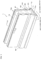
- FIG. 1 is a perspective view of an external appearance of an ink-jet head according to a first embodiment of the present invention.
- FIG. 2 is a sectional view taken along line II-II shown in FIG. 1 .
- an ink-jet head 1 includes a head main body 70 and a base block 71.
- the head main body 70 ejects ink to a paper acting as a recording medium.
- the base block 71 is disposed above the head main body 70, and has two ink reservoirs 3 formed therein.
- the ink-jet head 1 of this embodiment is fixed to a recording apparatus such as a line-type ink-jet printer, in such a manner that a widthwise direction of the ink-jet head 1 which means a sub scanning direction is in parallel with a paper conveyance direction.
- the head main body 70 includes a passage unit 4 in which an ink passage is formed.
- the passage unit 4 is constructed of thin plates laminated and bonded to each other.
- a bottom face of the head main body 70 serves as an ink ejection face (ejection face) 70a on which formed are many openings of nozzles (ink ejection ports) 8 each having a small diameter (see FIG. 5A ).
- FIG. 3 is a plan view of the head main body 70 as seen from above.
- the passage unit 4 has a rectangular shape elongated in its longitudinal direction, that is, in a main scanning direction.
- manifold channels 5 which are provided inside the passage unit 4 are illustrated with broken lines.
- Ten openings 3a are formed on an upper face of the passage unit 4.
- the ten openings 3a are arranged in two rows along the longitudinal direction of the passage unit 4, with each row including five openings 3a.
- Each of the openings 3a is connected to the manifold channel 5a.
- the openings 3a are connected to the ink reservoirs 3 of the base block 71.
- each manifold channel 5 branches into several sub manifold channels 5a.
- Each of the sub manifold channels 5a extends in parallel to the longitudinal direction of the passage unit 4.
- ink stored in the ink reservoirs 3 of the base block 71 goes through the openings 3a into the manifold channels 5 from which the ink is distributed to the respective sub manifold channels 5a each acting as a common ink chamber.
- each of the actuator units 21 has a trapezoidal shape with two acute angles, and is substantially laterally symmetrical.
- the four actuator units 21 are disposed with their parallel opposed sides, which mean shorter sides and longer sides, extending along the longitudinal direction of the passage unit 4.
- the four actuator units 21 are arranged substantially in a line along the longitudinal direction while center positions of the respective actuator units 21 are alternately and equidistantly shifted with respect to a widthwise direction of the passage unit 4.
- the four actuator units 21 are arranged in a zigzag pattern along the longitudinal direction of the passage unit 4. Neighboring ones of the four actuator units 21 are oriented in directions 180 degrees apart from each other. Accordingly, except for outermost two oblique sides, an oblique side of one actuator unit 21 is adjacent and in parallel to an oblique side of another actuator unit 21 neighboring to the one actuator unit 21. The two adjacent parallel oblique sides are partially within the same range with respect to the longitudinal direction. That is, the two adjacent parallel oblique sides partially overlap each other with respect to the longitudinal direction.
- a flexible printed circuit (FPC) 50 acting as a wire member is bonded to an upper face of each actuator unit 21.
- the FPC 50 extends leftward or rightward, and then extends upward while being bent, as shown in FIG. 2 .
- the pressure chamber group 9a has a trapezoidal shape of substantially the same size as a size of the actuator unit 21.
- the pressure chamber group 9b has a trapezoidal shape with two corners thereof being right-angled.
- the trapezoidal shape of the pressure chamber group 9b corresponds to a portion of the actuator unit 21 except an outer region 17 which will be described later.
- the four pressure chamber groups 9a and 9b are arranged substantially in a line along the longitudinal direction.
- the two pressure chamber groups 9a are sandwiched between the two pressure chamber groups 9b. Any of the pressure chamber groups 9a and 9b is made up of many pressure chambers 10 arranged in a matrix (see FIG. 4 ).
- each of the pressure chamber groups 9a and 9b is covered with the actuator unit 21.
- each actuator unit 21 has such a size as to cover the many pressure chambers 10 that constitute the pressure chamber group 9a or 9b.
- the above-described manifold channel 5 extends along between neighboring actuator units 21, and the sub manifold channels 5a branching therefrom are disposed in a region corresponding to where the pressure chamber group 9a or 9b exists.
- the base block 71 is made of a metal material such as stainless steel.
- the ink reservoir 3 formed in the base block 71 is a hollow region of substantially rectangular parallelepiped shape that extends along the longitudinal direction of the base block 71. Ink is supplied from an unillustrated ink tank to the ink reservoirs 3 which are thereby always filled up with ink.
- the ink reservoirs 3 have a total of ten openings 3b from which ink flows out.
- the ten openings 3b are arranged in two rows along a longitudinal direction of the ink reservoirs 3.
- the openings 3b are located at positions corresponding to the respective openings 3a of the passage unit 4. That is, in a plan view, the ten openings 3b of the ink reservoirs 3 and the ten openings 3a of the passage unit 4 are arranged to have the same positional relation.
- a portion 73a in the vicinity of each opening 3b protrudes downward lower than its surroundings. Only at the portion 73a of the lower face 73 in the vicinity of each opening 3b, the base block 71 is in contact with a portion of the upper face of the passage unit 4 in the vicinity of each opening 3a. Accordingly, a region of the base block 71 other than the portion 73a in the vicinity of each opening 3b is spaced apart from the head main body 70. In a space thus formed, the actuator units 21 are disposed.
- a holder 72 includes a support portion 72a and a pair of protruding portions 72b.
- the support portion 72a holds the base block 71.
- the protruding portions 72b are disposed at an interval from each other with respect to the sub scanning direction, and protrude upward from an upper face of the support portion 72a.
- the base block 71 is bonded and fixed within a concavity that is formed in a lower face of the support portion 72a of the holder 72.
- Each of the FPCs 50 connected to the actuator units 21 is disposed so as to extend along a surface of the protruding portion 72b of the holder 72 with an elastic member such as a sponge therebetween.
- a driver IC 80 is mounted on the FPC 50.
- the FPC 50 transmits a drive signal outputted from the driver IC 80, to the actuator unit 21 of the head main body 70.
- the FPC 50 is electrically bonded to the actuator unit 21 and the driver IC 80 with solder or the like.
- a heat sink 82 is disposed in close contact with an outer surface of the driver IC 80.
- the heat sink 82 dissipates heat that is generated in the driver IC 80.
- a substrate 81 to which one end of the FPC 50 is connected is disposed above the driver IC 80 and the heat sink 82.
- An upper face of the heat sink 82 is bonded to the substrate 81 with a seal member 84.
- a lower face of the heat sink 82 is bonded to the FPC 50 with a seal member 84. Dust and ink are thereby prevented from entering a main body of the ink-jet head 1.
- FIG. 4 shows on an enlarged scale a region enclosed with an alternate long and short dash line in FIG. 3 .
- four sub manifold channels 5a extend in a region within the passage unit 4 opposed to the actuator unit 21.
- Many individual ink passages 7 each extending to each nozzle 8 are connected to each of the sub manifold channels 5a.
- actuator units 21 are illustrated with broken lines though they should be illustrated with solid lines, while ink ejection ports 8a, pressure chambers 10, apertures 12, cavities 16a and the like, which actually should be illustrated with broken lines, are illustrated with solid lines.
- the pressure chamber groups 9a and 9b formed on an upper face 4a of the passage unit 4 are made up of many pressure chambers 10 each having a substantially rhombic shape in a plan view. Recesses formed on the upper face 4a of the passage unit 4 is closed with the actuator units 21, so that the pressure chambers 10 are defined.
- the pressure chamber 10 has a substantially rhombic shape in a plan view.
- Each pressure chamber 10 included in the pressure chamber groups 9a and 9b has one end thereof with respect to a longer diagonal communicating with a nozzle 8 and the other end thereof with respect to the longer diagonal communicating with a sub manifold channel 5a through an aperture 12 acting as a throttle.
- each of the imaginary planes K1 and K2 passes through an outer obtuse-angle vertex of each of the two outermost actuator units 21 which mean the two actuator units 21 not sandwiched between the other two actuator units 21 neighboring thereto.
- the active regions include active regions 19a and active regions 19b.
- the active regions 19a are trapezoidal regions each having the same shape as that of the actuator unit 21 and each enclosed by the contour of each of the two inner actuator units 21 which mean the two actuator units 21 sandwiched between the other two actuator units 21 neighboring thereto.
- Individual ink passages 7 provided in relation to the pressure chamber groups 9a are formed in the active regions 19a.
- the active regions 19b are trapezoidal regions each having two right angles.
- the active regions 19b exist inside the imaginary planes K1 and K2, and in addition each of the active regions 19b is enclosed by the contour of each of the two outer actuator units 21 in a plan view.
- Individual ink passages 7 provided in relation to the pressure chamber groups 9b are formed in the active regions 19b.
- pressure chambers 10 constituting the respective groups are regularly and adjacently arranged in a matrix in two directions, that is, in an arrangement direction A and an arrangement direction B.
- the arrangement direction A is the longitudinal direction of the passage unit 4, and extends in parallel to a shorter diagonal of the pressure chamber 10.
- the arrangement direction B is in parallel to one oblique side of the pressure chamber 10 forming an obtuse angle with the arrangement direction A.
- one pressure chamber 10 is surrounded by six other pressure chambers 10.
- the pressure chambers 10 are spaced apart from each other at intervals corresponding to 37.5 dpi, while with respect to the arrangement direction B sixteen pressure chambers 10 at the maximum are arranged. That is, the pressure chambers 10 are regularly arranged at fixed intervals along the arrangement direction A to thereby form pressure chamber rows 11, and sixteen pressure chamber rows 11 are arranged in parallel to each other to thereby form each pressure chamber group 9a, 9b. As a result of the pressure chambers 10 being arranged in this way, an image can be formed at a resolution of 600 dpi as a whole.
- a contour of the pressure chamber group 9a which means a contour of the active region 19a is a trapezoidal shape of substantially the same size as that of the actuator unit 21.
- a contour of the pressure chamber group 9b has a shape of "trapezoidal with two right angles" that is enclosed by the contour of the actuator unit 21 and the imaginary plane K1 or K2.
- the pressure chamber rows 11 are, depending on their position relative to the sub manifold channels 5a as seen in the direction perpendicularly crossing the drawing sheet of FIG. 4 , classified into first pressure chamber rows 11a, second pressure chamber rows 11b, third pressure chamber rows 11c, and fourth pressure chamber rows 11d.
- the first to fourth pressure chamber rows 11a to 11d are arranged periodically in an order of 11c, 11d, 11a, 11b, 11c, 11d, ...11b from the shorter side to the longer side of the actuator unit 21.
- ink ejection ports 8a corresponding to pressure chambers 10a included in the first pressure chamber rows 11a and ink ejection ports 8a corresponding to pressure chambers 10b included in the second pressure chamber rows 11b are concentrated at a lower side in FIG. 4 with respect to the direction perpendicular to the arrangement direction A.
- Each of the ink ejection ports 8a is opposed to a lower end portion of its corresponding pressure chamber 10.
- Ink ejection ports 8a corresponding to pressure chambers 10c included in the third pressure chamber rows 11c and ink ejection ports 8a corresponding to pressure chambers 10d included in the fourth pressure chamber rows 11d are concentrated at an upper side in FIG.
- each of the ink ejection ports 8a is opposed to an upper end portion of its corresponding pressure chamber 10.
- not less than half an area of each of the pressure chambers 10a and 10d included in the first and fourth pressure chamber rows 11a and 11d overlaps the sub manifold channel 5a.
- a substantially entire area of each of the pressure chambers 10b and 10c included in the second and third pressure chamber rows 11b and 11c does not overlap the sub manifold channel 5a.
- a width of a sub manifold channel 5a can be enlarged as wide as possible in order to smoothly supply ink to respective pressure chambers 10, while preventing the sub manifold channel 5a from overlapping nozzles 8 that communicate with pressure chambers 10 included in any of the pressure chamber rows 11.
- a peripheral cavity group 15 that encloses the pressure chamber group 9a is formed in a region of the upper face 4a of the passage unit 4 opposed to each of the two inner actuator units 21. Cavities included in the peripheral cavity group 15 are, like the pressure chambers 10, defined by recesses formed on the upper face 4a of the passage unit 4 being closed with the actuator unit 21.
- the peripheral cavity group 15 includes two kinds of cavities, that is, cavities 15a and cavities 15b.
- the cavities 15a are arranged in a line along each of the long and shorter sides of the actuator unit 21.
- the cavity 15a has the same shape and size as those of the pressure chamber 10.
- the cavities 15b are arranged in a line along each oblique side of the actuator unit 21.
- the cavity 15b has substantially the same shape and size as those of the pressure chamber 10.
- the cavity 15a constitutes a closed passage 55 that is in the shape of the individual ink passage 7 being partially closed (see FIG. 5C ).
- the cavity 15a as well constitutes a closed passage that is in the shape of the individual ink passage 7 being partially closed.
- a peripheral cavity group 16 that encloses the pressure chamber group 9b is formed in a region of the upper face 4a of the passage unit 4 opposed to each of the two outer actuator units 21. Cavities included in the peripheral cavity group 16 are, like the pressure chambers 10, defined by recesses formed on the upper face 4a of the passage unit 4 being closed with the actuator unit 21.
- the peripheral cavity group 16 includes four kinds of cavities, that is, cavities 16a, cavities 16b, cavities 16c, and cavities 16d.
- the cavities 16a are arranged in a line along each of the long and shorter sides of the actuator unit 21.
- the cavity 16a has the same shape and size as those of the pressure chamber 10.
- the cavities 16b are arranged in a line along an inner oblique side of the actuator unit 21.
- the cavities 16d are arranged in a line along an outer oblique side of the actuator unit 21.
- Each of the cavities 16b and 16d has substantially the same shape and size as those of the pressure chamber 10.
- the cavities 16c are arranged in a region (hereinafter referred to as an outer region 17) that is, in a plan view, enclosed by the contour of each of the two outer actuator units 21 and in addition located outside the active region 19b which means outside the imaginary plane K1 or K2.
- the cavities 16c are arranged continuously with the pressure chamber group 9b in the same pattern as that of the pressure chambers 10 included in the pressure chamber group 9b.
- the cavity 16c has the same shape and size as those of the pressure chamber 10.
- the cavity 16c is a part of a closed passage that is in the shape of the individual ink passage 7 being partially closed (see FIG. 5B ).
- a contour of the outer region 17 has a substantially right-angled triangle shape.
- cavity rows are formed extending in the arrangement direction A.
- the cavity rows include three kinds of cavities, that is, cavities 16a, cavities 16c, and cavities 16d.
- the cavity rows are arranged in such a manner that the number of cavities decreases as the cavity rows gets closer from the longer side to the shorter side of the actuator unit 21.
- recesses are regularly formed in the same pattern in a region of the upper face 4a of the passage unit 4 opposed to any pressure chamber 21. This can reduce load of design of the passage unit 4.
- peripheral cavity groups 15 and 16 are formed around the pressure chamber groups 9a and 9b, recesses surrounding an outermost one of the pressure chambers 10 of the pressure chamber groups 9a and 9b form the same pattern as that of recesses surrounding a pressure chamber 10 disposed on an inner side of the outermost ones. That is, in the pressure chamber groups 9a and 9b, many pressure chambers 10 are arranged into pressure chamber rows extending in the arrangement direction A or the arrangement direction B. In each of the pressure chamber rows, positions of neighboring pressure chambers 10 are shifted from each other at a predetermined interval in the arrangement direction A or the arrangement direction B.
- the peripheral cavity 15a, 15b, 16a, 16b, 16c, or 16d included in the peripheral cavity group 15 or 16 are formed at a position shifted in the arrangement direction A or the arrangement direction B at the same predetermined interval outward from the pressure chamber 10 that is located outermost in each of the pressure chamber rows with respect to the arrangement direction A or the arrangement direction B.
- the cavities 16c only the cavities 16c disposed adjacent to a boundary between the active region 19b and the outer region 17 are formed at such positions. This relation is established not only between the pressure chamber 10 and the cavity 15a, 15b, 16a, 16b, 16c, or 16d, but also between the individual ink passage and the closed passage which are partially made up of the pressure chamber 10 and the cavity, respectively.
- the closed passage that includes the cavity 15a, 15b, 16a, 16b, 16c, or 16d constituting the peripheral cavity group 15 or 16 is formed at a position shifted in the arrangement direction A or the arrangement direction B at the same predetermined interval outward from the individual ink passage 7 that is located outermost in each of individual ink passage rows with respect to the arrangement direction A or the arrangement direction B.
- a nozzle group (ejection port group) 18 is formed in a region of the ink ejection face 70a of the passage unit 4 overlapping each actuator unit 21.
- ink ejection ports 8a and openings 108a provided in relation to closed passages 14 (see FIG. 5B ) are arranged in a matrix.
- a contour of the nozzle group 18 is a trapezoidal shape slightly smaller than the actuator unit 21.
- the ink ejection ports 8a are formed at positions neighboring to the respective pressure chambers 10 and cavities 16c and not overlapping the sub manifold channels 5a.
- Each of the imaginary planes K1 and K2 passes through a boundary between where a length of a region defining the nozzle group 18 and a length of the actuator unit 21 intercepted by the imaginary plane K1 or K2 are constant regardless of a position of the imaginary plane K1 or K2 and where the lengths vary as the imaginary plane K1 or K2 is displaced in the longitudinal direction. That is, each of the imaginary planes K1 and K2 passes through an outer obtuse-angle vertex of the nozzle group 18 and an outer obtuse-angle vertex of the actuator unit 21. As seen from FIG. 4 , each of the imaginary planes K1 and K2 sections some of the pressure chambers 10 and cavities 16c disposed near the boundary between the active region 19b and the outer region 17.
- FIG. 5A is a sectional view taken along line VA-VA shown in FIG. 4 .
- FIG. 5B is a sectional view taken along line VB-VB shown in FIG. 4 .
- FIG. 5A shows an individual ink passage 7, and FIG. 5B shows a closed passage 14 including a cavity 16c.
- the individual ink passage 7 is provided corresponding to each pressure chamber 10 in the active regions 19a and 19b.
- the closed passage 14 is provided corresponding to each cavity 16c in the outer region 17.
- the individual ink passage 7 extends from an outlet 5b of a sub manifold channel 5a through an aperture 12 and a pressure chamber 10 to an ink ejection port 8a.
- the closed passage 14 including the cavity 16c has substantially the same shape as that of the individual ink passage 7 except that it is partially closed.
- the closed passage 14 does not communicate with a sub manifold channel 5a, as will be detailed later.
- the head main body 70 has a layered structure of ten sheet materials in total, namely, from the top, the actuator unit 21, a cavity plate 22, a base plate 23, an aperture plate 24, a supply plate 25, three manifold plates 26, 27, 28, a cover plate 29, and a nozzle plate 30, among which nine plates other than the actuator unit 21 constitute the passage unit 4.
- the cavity plate 22 is a metal plate in which many substantially rhombic holes constituting pressure chambers 10 and many holes constituting the cavities 15a, 15b, 16a to 16d are formed in regions where the actuator units are bonded.
- the base plate 23 is a metal plate in which formed are connection holes each connecting each pressure chamber 10 of the cavity plate 22 to a corresponding aperture 12 and connection holes each connecting each pressure chamber 10 to a corresponding nozzle 8. Also formed in the base plate 23 are connection holes each connecting each cavity 16c to a corresponding dummy aperture 112 and connection holes each connecting each cavity 16c to a corresponding dummy nozzle 108 having an opening 108a.
- the aperture plate 24 is a metal plate in which formed are holes serving as apertures 12 and connection holes each connecting each pressure chamber 10 to a corresponding nozzle 8. Also formed in the aperture plate 24 are holes serving as dummy apertures 112 and connection holes each connecting a cavity 16c to a corresponding dummy nozzle 108.
- the supply plate 25 is a metal plate in which formed are connection holes each connecting each aperture 12 to a sub manifold channel 5a (which means holes that constitute outlets 5b) and connection holes each connecting each pressure chamber 10 to a corresponding nozzle 8. Also formed in the supply plate 25 are connection holes each connecting each cavity 16c to a corresponding dummy nozzle 108.
- Each of the three manifold plates 26, 27, and 28 is a metal plate in which formed are holes constituting sub-manifold channels 5a and connection holes each connecting each pressure chamber 10 to a corresponding nozzle 8. Also formed in each of the three manifold plates 26, 27, and 28 are connection holes each connecting each cavity 16c to a corresponding dummy nozzle 108.
- the cover plate 29 is a metal plate in which formed are connection holes each connecting each pressure chamber 10 to a corresponding nozzle 8. Also formed in the cover plate 29 are connection holes each connecting each cavity 16c to a corresponding dummy nozzle 108.
- the nozzle plate 30 is a metal plate in which formed are nozzles 8 for the respective pressure chambers 10 and dummy nozzles 108 for the respective cavities 16c.
- the nine metal plates 22 to 30 are positioned in layers so as to form the individual ink passages 7 and the closed passages 14.
- the individual ink passage 7 firstly extends upward from the sub-manifold channel 5a, then extends horizontally in the aperture 12, then further extends upward, then again extends horizontally in the pressure chamber 10, then extends obliquely downward in a certain length away from the aperture 12, and then extends vertically downward toward the nozzle 8.
- a connection hole that connects the dummy aperture 112 to the sub manifold channel 5a (as illustrated with broken lines in FIG. 5B ) is not formed. More specifically, the dummy aperture 112 and an outlet of the sub manifold channel 5a are not connected but a portion between them is closed. Therefore, the closed passage 14 is an isolated passage supplied with no ink and extending from the dummy aperture 112 through the cavity 16c to the dummy nozzle 108. All the closed passages 14 do not communicate with the sub manifold channel 5a.
- FIG. 5C shows a sectional view of the closed passage 55 including the cavity 15a.
- the closed passage 55 including the cavity 15a is in the shape of the individual ink passage being entirely closed except the cavity 15a.
- Each of the closed passages including the other cavities 15b, 16a, 16b, and 16d has the same cross section as that of the closed passage 55 shown in FIG. 5C .
- the term "closed passage 55" means not only a closed passage corresponding to the cavity 15a, but sometimes also a closed passage corresponding to the cavity 15b, 16a, 16b, or 16d.
- FIG. 6A is a sectional view showing on an enlarged scale a part around a boundary between the actuator unit 21 and the passage unit 4.
- a construction shown in FIG. 6A is common to a cross section including the pressure chamber 10 and a cross section including the cavity 16c.
- the actuator unit 21 has a layered body in which three piezoelectric sheets 41 to 43 are put in layers. Each of the three piezoelectric sheets 41 to 43 has a thickness of 15 ⁇ m.
- Each of the piezoelectric sheets 41 to 43 is configured as a continuous layer-like flat plate (continuous flat layer) extending over many pressure chambers 10 included in the pressure chamber groups 9a, 9b and cavities 15a, 15b, 16a to 16d included in the peripheral cavity groups 15, 16.
- the piezoelectric sheets 41 to 43 are made of a lead zirconate titanate (PZT)-base ceramic material having ferroelectricity.
- Individual electrodes 35 each having a thickness of approximately 1 ⁇ m are formed on the uppermost piezoelectric sheet 41.
- the individual electrodes 35 are opposed to the respective pressure chambers 10 and cavities 16c.
- a common electrode 34 having a thickness of approximately 2 ⁇ m is interposed between the piezoelectric sheet 41 and the piezoelectric sheet 42 disposed under the piezoelectric sheet 41.
- the common electrode 34 has the same shape as that of the piezoelectric sheet 41.
- No electrode is disposed between the piezoelectric sheets 42 and 43. Consequently, only the uppermost piezoelectric sheet 41 is an active layer including a portion that works as an active portion when an electric field is applied thereto.
- the piezoelectric sheets 42 and 43 are inactive layers including no active portion.
- Both the individual electrodes 35 and the common electrode 34 are made of, e.g., an Ag-Pd-base metallic material.
- FIG. 6B is a partial plan view showing on an enlarged scale a shape of the individual electrode formed on a surface of the actuator unit 21.
- a shape of the individual electrode 35 is substantially rhombic and substantially similar to that of the pressure chamber 10 or the cavity 16c.
- a large part of the individual electrode 35 falls within the pressure chamber 10 or the cavity 16c.
- the substantially rhombic individual electrode 35 has its one acute portion extending out, and a circular land 36 having an approximately 160 ⁇ m is provided on an end of an extending-out portion thus formed.
- the land 36 is electrically bonded to the individual electrode 35.
- the land 36 is a conductive member made of gold including glass frits. As shown in FIG. 6A , the land 36 is not opposed to the pressure chamber 10 or the cavity 16c.
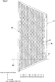
- FIG. 7 is a plan view of the actuator unit 21 having the imaginary plane K2 passing therethrough.
- This actuator unit 21 has the same structure as those of the other three actuator units 21.
- the individual electrodes 35 formed on the actuator unit 21 are arranged in the same pattern as that of the pressure chambers 10 and the cavities 16c.
- the individual electrodes 35 form an individual electrode group 38. Since individual electrode groups 38 are formed on the other three actuator units 21 as well, there are four individual electrode groups 38 on the head main body 70.
- the individual electrode group 38 is made up of individual electrode rows 39.
- Each of the individual electrode rows 39 includes individual electrodes 35 formed along the main scanning direction.
- the number of individual electrodes 35 included in each individual electrode row 39 decreases as the individual electrode row 39 gets closer from the longer side to the shorter side of the actuator unit 21. Consequently, a contour of the individual electrode group 38 is a trapezoidal shape substantially similar to the contour of the actuator unit 21.
- the imaginary plane K1, K2 passes through a boundary between where a length of a region defining the individual electrode group 38 intercepted by the imaginary plane K1, K2 is constant regardless of a position of the imaginary plane K1, K2 and where the length varies as the imaginary plane K1, K2 is displaced in the longitudinal direction. That is, the imaginary plane K1, K2 passes through an outer obtuse-angle vertex of the individual electrode group 38.
- Common electrode terminals 37 are provided near four corners of an upper face of the actuator unit 21.
- the common electrode terminals 37 are electrically connected to the common electrode 34 via through-hole electrodes that penetrate the piezoelectric sheet 41.
- the common electrode 34 is grounded through the common electrode terminals 37 and the FPC 50. Consequently, the common electrode 34 is, in its portions corresponding to all the pressure chambers 10, equally kept at the ground potential.
- the individual electrodes 35 are, through the lands 36 and the FPC 50, electrically connected to respective terminals of the driver IC 80. A drive signal supplied from the driver IC 80 is thus supplied to the individual electrode 38.
- the piezoelectric sheet 41 of the actuator unit 21 is polarized in its thickness direction. That is, the actuator unit 21 has a so-called unimorph-type structure in which the piezoelectric sheet 41 is an active layer while the piezoelectric sheets 42 to 43 existing between the active layer and the pressure chambers 10 are inactive layers. Accordingly, when an individual electrode 35 is set at a positive or negative predetermined potential and a direction of an electric field is the same as a polarization direction for example, a portion of the piezoelectric sheet 41 sandwiched between electrodes and applied with the electric field acts as an active portion, i.e., a pressure generating portion, and deforms in a direction perpendicular to the polarization direction.
- the piezoelectric sheets 42 and 43 are not affected by the electric field and do not deform by themselves. As a result, difference in distortion in a direction perpendicular to the polarization direction occurs between the upper piezoelectric sheet 41 and the lower piezoelectric sheets 42, 43, so that the piezoelectric sheets 41 to 43 as a whole deform protrudingly toward a pressure chamber 10 (unimorph deformation).
- a lower face of the actuator unit 21 is fixed to an upper face of a wall (cavity plate 22) that partitions the pressure chambers. Consequently, a portion corresponding to the individual electrode 35 deforms protrudingly toward the pressure chamber 10.
- an individual electrode 35 is in advance set at a potential different from that of the common electrode 34. Upon every ejection request, the individual electrode 35 is once set at the same potential as that of the common electrode 34, and then at a predetermined timing the individual electrode 35 is again set at a potential different from that of the common electrode 34.
- the piezoelectric sheets 41 to 43 restore their original shapes and thus the volume of a pressure chamber 10 becomes larger than in an initial state where the potential of individual electrode 35 is different from the potential of the common electrodes 34. Ink is accordingly sucked from a sub manifold channel 5a into the pressure chamber 10.
- the piezoelectric sheets 41 to 43 deform protrudingly toward the pressure chamber 10. This reduces the volume of the pressure chamber 10 thus raising ink pressure, so that ink is ejected from a nozzle 8.
- the individual electrodes 35 are formed also in a region of the actuator unit 21 opposed to the cavities 16c. However, even when an individual electrode 35 corresponding to a cavity 16c is driven, no ink is ejected, because the cavity 16c is an isolated passage not communicating with a sub manifold channel 5a. Therefore, a drive signal may either be or not be supplied to the individual electrode 35 that is formed corresponding to the cavity 16c.
- FIG. 8 shows on an enlarged scale a region enclosed with an alternate long and short dash line in FIG. 4 .
- a band region R shown in FIG. 8 will be discussed.
- the band region R has a width corresponding to 37.5 dpi, that is, a width of 678.0 ⁇ m, along the arrangement direction A.
- the band region R is elongated in a direction perpendicular to the arrangement direction A.
- any of the sixteen pressure chamber rows 11a to 11d includes only one ink ejection port 8a.
- the band region R is set, there are always a total of sixteen nozzles 8, each included in each of the sixteen pressure chamber rows 11a to 11d, within the band region R.
- sixteen nozzles 8 included in one band region R are denoted by (1) to (16) sequentially from the one whose projective point is located at the most left on the imaginary line L, these sixteen nozzles 8 are arranged in an order of, from a lower side, (1), (9), (5), (3), (13), (11), (7), (2), (15), (10), (6), (4), (14), (12), (8), and (16).
- sixteen pressure chambers 10 corresponding to sixteen nozzles 8 included in one band region R are denoted by (1) to (16) sequentially from the one located at the most left with respect to a direction along the imaginary line L, these sixteen pressure chambers 10 are arranged in an order of, from a lower side, (1), (9), (5), (13), (3), (11), (7), (15), (2), (10), (6), (14), (4), (12), (8), and (16).
- the ink ejection ports 8a when making a comparison between arrangement of the ink ejection ports 8a and arrangement of the pressure chambers 10 within the band region R, they are replaced in fourth and fifth rows, in eighth and ninth rows, and in twelfth and thirteenth rows, respectively. This is because the pressure chambers 10 are arranged at a high density and in addition the ink ejection ports 8a are maldistributed.
- characters, figures, and the like can be formed at a resolution of 600 dpi, by properly driving the actuator unit 21 in accordance with conveyance of a paper.
- ink is ejected in synchronization with conveyance of a paper from nozzles 8 in an order of (1), (9), (5), (3), (13), (11), (7), (2), (15), (10), (6), (4), (14), (12), (8), and (16) in a case where the paper is conveyed from down to top in FIG. 8 . Since each end portion of each nozzle group 18 with respect to the arrangement direction A makes a complementarity relation with an end portion of another neighboring nozzle group 18, a printing resolution of 600 dpi can be realized over a range covering the four nozzle groups 18.
- the closed passages 14 and 55 that do not communicate with the sub manifold channels 5a are formed in the passage unit 4.
- the closed passage 14, 55 is formed at a position shifted in the arrangement direction A or the arrangement direction B at the above-mentioned predetermined interval outward from the individual ink passage 7 that is located outermost in each of the individual ink passage rows with respect to the arrangement direction A or the arrangement direction B.
- the closed passages 14 corresponding to the cavities 16c only the closed passages 14 disposed adjacent to the boundary between the active region 19b and the outer region 17 are formed at such positions. This can reduce variation in rigidity among regions surrounding the respective individual ink passages 7 in the active regions 19a and 19b.
- any individual ink passage 7 exhibits substantially the same ink ejection performance.
- the peripheral cavity groups 15 and 16 contribute to ink ejection in a sense of reducing variation in ink ejection performance depending on a location within the pressure chamber groups 9a and 9b.
- a degree of this effect is affected by a size and a location of a cavity left in the closed passage 14, 55.
- the above-described effect can be obtained though its degree may vary.
- the cavities 15a, 15b, 16a, 16b, 16c, and 16d which are equivalent to the pressure chambers 10 in height level, greatly affect ink ejection performance of the active regions 19a and 19b, in terms of rigidity of regions surrounding the respective individual ink passages 7 including these pressure chambers 10. Therefore, when like in this embodiment the closed passages 14 and 15 have cavities formed at the same level as the pressure chambers 10 are, variation in rigidity among regions surrounding the respective individual ink passages 7 is greatly reduced, so that variation depending on locations of the individual ink passages is greatly reduced.
- some cavities 16c existing in the outer region 17 most largely contribute to ink ejection in the sense of reducing variation in ink ejection performance depending on a location within the pressure chamber group 9b.
- the other cavities 16c existing in the outer region 17 also serve to reduce variation in ink ejection performance depending on a location within the pressure chamber group 9b, though a degree of the service is smaller than that of the some cavities 16c disposed adjacent to the boundary.
- the four actuator units 21 are given the same structure in view of production efficiency. Therefore, the individual electrodes 35 are distributed substantially over a whole area of the actuator unit 21. However, some of the individual electrodes 35 formed in the outermost two actuator units, that is, individual electrodes 35 existing in the outer regions 17, are not used for a printing operation. This is because, since each of the actuator units 21 has a trapezoidal shape, the individual electrodes 35 existing in the outer region 17 cannot establish a complementarity relation with individual electrodes 35 formed on another neighboring actuator unit 21 and therefore cannot print an image at a predetermined resolution.
- the FPC 50 which is a wire member that gives a drive signal to the individual electrode 35 of the actuator unit 21, and a drive signal that is given for the head 1 to perform a purge operation are common to all the actuator units 21. Therefore, if, instead of the closed passage 14, a passage like the individual ink passage 7 communicating from a sub manifold channel 5b to an ejection port is formed in the outer region 17, ink is wastefully consumed and besides air bubbles may enter the sub manifold channel 5a. In this embodiment, however, the closed passages 14 each having the same shape as that of the individual ink passage 7 are formed in the passage unit 4 in the same pattern as an arrangement pattern of the individual ink passages 7. As a result, the advantageous effects as mentioned above can be obtained while reducing load of design as much as possible.
- connection holes connecting the closed passages 14 and 55 to the sub manifold channels 5a are not formed in the supply plate 25. Therefore, when ink is initially introduced into the sub manifold channels 5a, the closed passages 14 and 55 are not filled with the ink. The ink can be saved accordingly. Moreover, at the initial introduction, no air bubbles stay around such connection holes. If air bubbles stay around the connection holes, the air bubbles may return to the sub manifold channel 5a and enter the individual ink passages 7 that are connected to the sub manifold channel 5a. This may cause ink ejection failure. Even without such reverse flow of air bubbles, components of the air may blend into ink to cause abnormal ink ejection performance. In this embodiment, however, good ink ejection is not hindered because no air bubbles stay around the connection holes.
- the four actuator units 21 have the same shape, manufacturing of the actuator unit 21 is easier. In addition, since the four actuator units 21 are arranged in two rows in a zigzag pattern along the main scanning direction, it is easier to fix the four actuator units 21 to the passage unit 4. Moreover, since the number of actuator units 21 is equal to or more than three (four in this embodiment), a large-length head suitable for a line printer can be realized. Further, since the actuator unit 21 has a trapezoidal shape with two acute angles, it is easier to design the actuator unit 21.
- the imaginary plane K1, K2 that is, a boundary between the active region 19b and the outer region 17, passes through a boundary between where lengths of the region defining the nozzle group 18, the region defining the individual electrode group 38, and the actuator unit 21 intercepted by the imaginary plane K1, K2 are constant regardless of a position of the imaginary plane K1, K2 and where the lengths vary as the imaginary plane K1, K2 is displaced in the longitudinal direction. Therefore, the boundary between the active region 19b and the outer region 17 can clearly be seen from its external appearance. Thus, in assembling the ink-jet head 1 to a printer, a paper which will be conveyed and the active regions 19a, 19b can be positioned to each other with high accuracy.
- FIG. 5B illustrates, as an example, that a closed passage is closed between a counterpart to an outlet of a common ink chamber in an individual ink passage and a counterpart to an inlet of a pressure chamber in the individual ink passage.
- FIG. 5C illustrates, as an example, that a closed passage is closed between a counterpart to an outlet of a common ink chamber in an individual ink passage and a counterpart to an inlet of a pressure chamber in the individual ink passage.
- FIG. 5C illustrates, as an example, that a closed passage is closed between a counterpart to an outlet of a common ink chamber in an individual ink passage and a counterpart to an inlet of a pressure chamber in the individual ink passage.
- the connection holes each connecting each cavity 16c to a corresponding dummy aperture 112 are not formed in the base plate 23, and the holes serving as dummy apertures 112 are not formed in the aperture plate 24.
- the cavity plate 22 has the cavities 16c formed within the outer region 17 and adjacently to the active region 19b. Therefore, recesses surrounding an outermost one of the pressure chambers 10 of the pressure chamber group 9b which is adjacent to the outer region 17 form the same pattern as that of recesses surrounding a pressure chamber 10 disposed on an inner side of the outermost ones. As a result, variation in rigidity among regions surrounding the respective individual ink passages 7 within the pressure chamber group 9b is reduced, so that variation in ink ejection performance of the individual ink passages depending on their locations can be reduced.
- FIG. 9 is a partial plan view showing on an enlarged scale a head main body of an ink-jet head according to a second embodiment of the present invention.
- FIG. 10 is a sectional view taken along line X-X shown in FIG. 9 .
- the same members as in the first embodiment will be denoted by the same reference numerals, without a specific description thereof.
- An ink-jet head of this embodiment is similar to that of the first embodiment except that a passage unit 204 of a head main body 270 is a little different from the passage unit 4 of the first embodiment.
- pressure chamber groups 9a and 209b are formed in regions opposed to respective actuator units 21.
- Peripheral cavity groups 215 and 216 are also formed so as to enclose the pressure chamber groups 9a and 209b, respectively.
- the peripheral cavity group 215 is the same as the peripheral cavity group 15 of the first embodiment.
- the pressure chamber group 209b is formed substantially in the same manner as the pressure chamber group 9b is.
- pressure chambers 10 arranged in a matrix form an active region 19b.
- the peripheral cavity group 216 includes cavities 16a, 16b, and 216c. Each one of the cavities 216c is disposed on an outer side of each pressure chamber row 11 that constitutes the active region 19b.
- the peripheral cavity group 216 is the same as the peripheral cavity group 16 of the first embodiment except that it includes no cavities 16d and a reduced number of cavities 16c.
- recesses surrounding an outermost one of the pressure chambers 10 of the pressure chamber group 9a, 209b form the same pattern as that of recesses surrounding a pressure chamber 10 disposed on an inner side of the outermost ones. Therefore, the same effect as in the first embodiment can be presented, in that any individual ink passage 7 exhibits substantially the same ink ejection performance because variation in rigidity among regions surrounding respective individual ink passages 7 including the pressure chambers 10 is reduced.
- the head main body 270 has a layered structure of the actuator unit 21 and nine plates 222 to 230, like in the first embodiment.
- each of the plates 222 to 230 that constitute the passage unit 204 has, within the active regions 19a and 19b, holes corresponding to individual ink passages 7.
- all formed in the plates 222 to 230 constituting the passage unit 204 are no more than holes serving as the cavities 216c and holes serving as sub manifold channels 5a.
- the holes serving as the cavities 216c are formed in the cavity plate 222 which is the uppermost one of the nine plates 222 to 230.
- the holes serving as sub manifold channels 5a are formed in the three sub manifold plates 226 to 228. That is, the eight plates 223 to 230 other than the cavity plate 222 have no holes for forming closed passages 56 that include the cavities 216c (as illustrated with broken lines in FIG. 10 ).
- the closed passages 56 formed in the outer region 217 of the passage unit 204 are the closed passages 56 made up only of the cavities 216c and communicating with neither outside nor the sub manifold channel 5b. Both openings of the cavity 216c constituting the closed passage 56 are closed by the base plate 223 and the actuator unit 21. Both openings of the other cavities 15a, 15b, 16a, and 16b are also closed by the base plate 223 and the actuator unit 21.
- the above-described ink-jet head of the second embodiment presents the same advantageous effects as obtained by the ink-jet head 1 of the first embodiment, and also presents an advantageous effect that due to a reduced number of cavities 216c, the passage unit 204 is easier to manufacture than the passage unit 4 of the first embodiment.
- manufacturing of the passage unit 204 can be simplified all the more.
- FIG. 11 is a sectional view showing this embodiment in correspondence with FIG. 5B .
- a closed passage 57 shown in FIG. 11 differs from the closed passage 14 of the first embodiment only in that, with respect to each cavity 16c, a supply plate 25 has a connection hole connecting a dummy aperture 112 to a sub manifold channel 5a (which means a hole constituting an outlet 5b) and a nozzle plate 30 has no through hole.
- Closed passages corresponding to cavities 15a, 15b, 16a, 16b, and 16d other than 16c have the same cross-section structure as shown in FIG. 11 .
- FIG. 11 illustrates, as an example, that a closed passage is closed between a counterpart to an outlet of a pressure chamber in an individual ink passage and a counterpart to an ink ejection port in the individual ink passage.
- FIG. 5C Another example of the same case is illustrated in FIG. 5C .
- the connection holes each connecting each cavity 16c to a corresponding dummy nozzle 108 are not formed in at least one of the plates 23 to 29.
- the closed passage may be provided anywhere in the passage unit.
- the closed passage may be closed in a counterpart to any portion of the individual ink passage.
- a boundary between the active region and the outer region passes through an obtuse-angle vertex of the actuator unit, an obtuse-angle vertex of the region defining the individual electrode group, an obtuse-angle vertex of the individual electrode group. It may be possible that a position of the obtuse-angle vertex of the actuator unit, a position of the obtuse-angle vertex of the region defining the individual electrode group, a position of the obtuse-angle vertex of the individual electrode group are shifted with respect to
- Two actuator units may be fixed to the passage unit, or alternatively four or more actuator units may be fixed to the passage unit.
- the actuator unit may have any shape in a plan view.
Claims (15)
- Tête à jet d'encre comprenant :une unité de passage (4) dans laquelle sont formées une chambre d'encre commune (5a) et une pluralité de passages d'encre individuels (7), chacun s'étendant depuis une sortie de la chambre d'encre commune (5a) via une chambre de pression (10) vers un orifice d'éjection d'encre (8a) ; etune pluralité d'unités formant actionneurs (21) qui sont fixées sur un plan défini par une surface de l'unité de passage (4) et communiquent une énergie d'éjection à l'encre dans chaque chambre de pression (10), la pluralité d'unités d'actionneurs (21) présentant la même forme,dans laquelle une pluralité de passages fermés (14, 55) présentant chacun la forme du passage d'encre individuel (7) et qui ne communiquent pas avec la chambre d'encre commune (5a) sont formés sur l'unité de passage (4),lorsque des orifices d'une pluralité d'orifices d'éjection d'encre (8a) correspondant à une pluralité de chambres de pression (10) s'étendent dans une direction perpendiculaire à une ligne imaginaire (L) qui est parallèle au plan, leurs points de projection sur la ligne imaginaire (L) sont alignés à intervalles réguliers ; etles passages d'encre de la pluralité passages d'encre individuels (7) sont formés régulièrement dans des zones actives (19a, 19b), chaque zone active étant entourée par un contour correspondant à l'une des unités d'actionneurs (21) sur une vue en plan, et les zones de la pluralité de zones actives (19a, 19b) étant en outre situées entre les deux extrémités, par rapport à une direction de la ligne imaginaire (L), définies par des positions des deux points de projection situés le plus à l'extérieur sur la ligne imaginaire (L) ;dans laquelle les passages de la pluralité de passages fermés (14, 55) sont agencés dans des zones externes (17), chaque zone externe (17) étant entourée par le contour de l'une correspondante des deux unités d'actionneurs (21) les plus à l'extérieur sur une vue en plan, et les zones externes (17) étant en outre situées à l'extérieur des zones actives (19a, 19b) par rapport à la direction de la ligne imaginaire (L), suivant le même profil que celui de la pluralité de passages d'encre individuels (7) dans les zones actives (19a, 19b),dans laquelle les passages d'encre de la pluralité de passages d'encre individuels (7) sont agencés en une pluralité de rangées de passages d'encre s'étendant suivant une première direction d'agencement (A), dans laquelle la ligne imaginaire (L) s'étend dans la première direction d'agencement (A), etcaractérisée en ce queseuls les passages de la pluralité de passages fermés (14, 55) sont agencés dans les zones externes (17),dans laquelle chaque limite entre les zones actives les plus à l'extérieur (19b) et les deux zones externes (17) existe au niveau d'une limite entre l'endroit où une longueur de l'unité d'actionneur (21) interceptée par un plan imaginaire (K1, K2) qui est perpendiculaire à la ligne imaginaire (L) est constante indépendamment d'une position du plan imaginaire et l'endroit où la longueur varie à mesure que le plan imaginaire (K1, K2) est déplacé.
- Tête à jet d'encre selon la revendication 1, dans laquelle :les passages d'encre de la pluralité de passages d'encre individuels (7) sont aussi agencés en une pluralité de rangées de passages d'encre individuels s'étendant dans une seconde direction d'agencement (B) formant un angle obtus avec la première direction d'agencement (A), d'une manière telle que, sur chacune des rangées de passages d'encre individuels, des positions de passages d'encre individuels voisins sont décalées l'une de l'autre suivant un intervalle prédéterminé dans la seconde direction d'agencement (B) ; etau moins l'un de la pluralité de passages fermés (14, 55) est formé à une position décalée dans la seconde direction d'agencement (B) vers l'extérieur à partir des passages d'encre individuels (7) qui sont situés le plus à l'extérieur sur chacune des rangées par rapport à la seconde direction d'agencement (B).
- Tête à jet d'encre selon la revendication 2, dans laquelle le au moins un de la pluralité de passages fermés (55) est formé à une position décalée dans la seconde direction d'agencement (B) avec l'intervalle prédéterminé vers l'extérieur des passages d'encre individuels (7) qui sont situés le plus à l'extérieur sur chacune des rangées par rapport à la seconde direction d'agencement (B).
- Tête à jet d'encre selon l'une quelconque des revendications 1 à 3, dans laquelle chaque passage fermé (14, 55) n'est pas fermé sur sa partie agencée au même niveau que la chambre de pression (10) par rapport à une direction perpendiculaire au plan.
- Tête à jet d'encre selon l'une quelconque des revendications 1 à 4, dans laquelle chaque passage fermé (14, 55) est fermé entre une partie en regard d'une sortie (5a) de la chambre d'encre commune sur le passage d'encre individuel (7) et une partie en regard d'une entrée de la chambre de pression sur le passage d'encre individuel.
- Tête à jet d'encre selon la revendication 5, dans laquelle chaque passage fermé (14, 55) est fermé sur une partie en regard d'une sortie (5a) de la chambre d'encre commune sur le passage d'encre individuel.
- Tête à jet d'encre selon l'une quelconque des revendications 1 à 4, dans laquelle chaque passage fermé (14, 55) est fermé entre une partie en regard d'une sortie de la chambre de pression sur le passage d'encre individuel et une partie en regard (108) de l'orifice d'éjection d'encre sur le passage d'encre individuel.
- Tête à jet d'encre selon la revendication 7, dans laquelle chaque passage fermé (14, 55) est fermé sur une partie en regard (108) de l'orifice d'éjection d'encre sur le passage d'encre individuel.
- Tête à jet d'encre selon l'une quelconque des revendications 1 à 8, dans laquelle :chaque passage fermé (14, 55) n'est pas fermé sur une partie en regard de l'orifice d'éjection d'encre sur le passage d'encre individuel ;sur une face d'éjection (70a) sur laquelle est formée une pluralité d'orifices d'éjection d'encre (8a) et qui s'étend parallèlement au plan, une pluralité d'orifices d'éjection d'encre (8a) et une pluralité d'ouvertures (108a) agencées au niveau de la pluralité de passages fermés (14, 55) constituent une pluralité de groupes d'orifices d'éjection qui correspondent aux unités d'actionneurs (21) ; etchaque limite entre les zones actives les plus à l'extérieur (19a, 19b) et les deux zones externes (17) existe au niveau d'une limite entre l'endroit où une longueur d'une zone définissant la pluralité de groupes d'orifices d'éjection interceptés par un plan imaginaire (K1, K2) qui est perpendiculaire à la ligne imaginaire (L) est constante indépendamment d'une position du plan imaginaire et l'endroit où la longueur varie à mesure que le plan imaginaire (K1, K2) est déplacé.
- Tête à jet d'encre selon l'une quelconque des revendications 1 à 8, dans laquelle :chaque unité d'actionneur (21) comporte une électrode commune (34) commune à la pluralité de chambres de pression (10) et maintenue à un potentiel constant, une pluralité d'électrodes individuelles (35) disposées de manière à être opposées respectivement à la pluralité de chambres de pression (10), et alimentées avec un signal d'attaque destiné à attaquer l'unité d'actionneur (21), et une couche piézo-électrique (41) intercalée entre l'électrode commune (34) et la pluralité d'électrodes individuelles (35) ;la pluralité d'électrodes individuelles constitue un groupe électrode individuel sur la couche piézo-électrique (41) ; etchaque limite entre les zones actives les plus à l'extérieur (19b) et les deux zones externes (17) existe à une limite entre l'endroit où une longueur d'une zone définissant une pluralité de groupes électrodes individuels interceptés par un plan imaginaire (K1, K2) qui est perpendiculaire à la ligne imaginaire (L) est constante indépendamment d'une position du plan imaginaire (K1, K2) et l'endroit où la longueur varie à mesure que le plan imaginaire (K1, K2) est déplacé.
- Tête à jet d'encre selon l'une quelconque des revendications 1 à 10, dans laquelle la pluralité d'unités d'actionneurs (21) est agencée dans la première direction d'agencement (A) sur le plan de l'unité de passage.
- Tête à jet d'encre selon la revendication 11, dans laquelle, sur une vue en plan, la pluralité d'unités d'actionneurs (21) présente une forme quadrangulaire avec deux angles aigus.
- Tête à jet d'encre selon l'une quelconque des revendications 1 à 12, dans laquelle :chaque passage fermé (14) disposé de manière adjacente à chaque limite entre les zones actives les plus à l'extérieur (19b) et les deux zones externes (17) n'est pas fermé dans sa partie agencée au même niveau que la chambre de pression (10) par rapport à une direction perpendiculaire au plan.
- Tête à jet d'encre selon l'une quelconque des revendications 1 à 13, dans laquelle les passages de la pluralité de passages fermés (14, 55) sont agencés au-dessus de la totalité de la circonférence de la zone active (19a, 19b).
- Tête à jet d'encre selon la revendication 1,
dans laquelle quatre ou plusieurs des unités d'actionneurs (21) sont agencées dans la première direction d'agencement (A) sur le plan de l'unité de passage (4), et
l'agencement de la pluralité de passages d'encre individuels (7) et de la pluralité de passages fermés (14, 55) dans une zone à l'intérieur de l'unité de passage opposée à la première des unités d'actionneur la plus à l'extérieur est identique à celui de la pluralité de passages d'encre individuels (7) et de la pluralité de passages fermés (14, 55) dans une zone à l'intérieur de l'unité de passage (4) opposée à l'autre des unités d'actionneur la plus à l'extérieur.
Applications Claiming Priority (1)
| Application Number | Priority Date | Filing Date | Title |
|---|---|---|---|
| JP2006002699A JP4561637B2 (ja) | 2006-01-10 | 2006-01-10 | インクジェットヘッド |
Publications (3)
| Publication Number | Publication Date |
|---|---|
| EP1806228A2 EP1806228A2 (fr) | 2007-07-11 |
| EP1806228A3 EP1806228A3 (fr) | 2008-12-03 |
| EP1806228B1 true EP1806228B1 (fr) | 2017-03-22 |
Family
ID=37909424
Family Applications (1)
| Application Number | Title | Priority Date | Filing Date |
|---|---|---|---|
| EP07000137.5A Active EP1806228B1 (fr) | 2006-01-10 | 2007-01-04 | Tête à jet d'encre |
Country Status (4)
| Country | Link |
|---|---|
| US (1) | US7654650B2 (fr) |
| EP (1) | EP1806228B1 (fr) |
| JP (1) | JP4561637B2 (fr) |
| CN (1) | CN100999155B (fr) |
Families Citing this family (2)
| Publication number | Priority date | Publication date | Assignee | Title |
|---|---|---|---|---|
| JP5510119B2 (ja) * | 2010-06-29 | 2014-06-04 | セイコーエプソン株式会社 | 液体噴射ヘッドおよび液体噴射装置 |
| US11571896B2 (en) * | 2021-02-01 | 2023-02-07 | Funai Electric Co., Ltd. | Customization of multichannel printhead |
Family Cites Families (9)
| Publication number | Priority date | Publication date | Assignee | Title |
|---|---|---|---|---|
| JP3088890B2 (ja) * | 1994-02-04 | 2000-09-18 | 日本碍子株式会社 | 圧電/電歪膜型アクチュエータ |
| EP1138493B1 (fr) * | 2000-03-21 | 2007-05-23 | Fuji Xerox Co., Ltd. | Tête à jet d'encre |
| JP2001301171A (ja) * | 2000-04-25 | 2001-10-30 | Seiko Epson Corp | インクジェットヘッド |
| JP3922004B2 (ja) * | 2001-11-30 | 2007-05-30 | ブラザー工業株式会社 | インクジェットプリンタヘッド |
| JP4539064B2 (ja) * | 2002-09-26 | 2010-09-08 | ブラザー工業株式会社 | インクジェットヘッド |
| US6969158B2 (en) * | 2002-09-26 | 2005-11-29 | Brother Kogyo Kabushiki Kaisha | Ink-jet head |
| JP3876854B2 (ja) * | 2003-06-30 | 2007-02-07 | ブラザー工業株式会社 | インクジェットヘッド |
| JP3885783B2 (ja) * | 2003-08-14 | 2007-02-28 | ブラザー工業株式会社 | インクジェットヘッド |
| JP4419754B2 (ja) * | 2004-08-27 | 2010-02-24 | ブラザー工業株式会社 | インクジェットヘッド |
-
2006
- 2006-01-10 JP JP2006002699A patent/JP4561637B2/ja active Active
-
2007
- 2007-01-04 EP EP07000137.5A patent/EP1806228B1/fr active Active
- 2007-01-08 US US11/620,802 patent/US7654650B2/en active Active
- 2007-01-10 CN CN2007100022335A patent/CN100999155B/zh active Active
Non-Patent Citations (1)
| Title |
|---|
| None * |
Also Published As
| Publication number | Publication date |
|---|---|
| US7654650B2 (en) | 2010-02-02 |
| CN100999155A (zh) | 2007-07-18 |
| US20070159513A1 (en) | 2007-07-12 |
| EP1806228A2 (fr) | 2007-07-11 |
| EP1806228A3 (fr) | 2008-12-03 |
| JP4561637B2 (ja) | 2010-10-13 |
| CN100999155B (zh) | 2010-05-26 |
| JP2007182028A (ja) | 2007-07-19 |
Similar Documents
| Publication | Publication Date | Title |
|---|---|---|
| US7008049B2 (en) | Inkjet head | |
| EP1403053B1 (fr) | Tête jet d'encre | |
| EP1547775B1 (fr) | Tête à jet d'encre | |
| EP1336495B1 (fr) | Tête à jet d'encre et imprimante à jet d'encre | |
| EP0755791B1 (fr) | Organe d'actionnement pour une tête d'enregistrement à jet d'encre et procédé de fabrication de celle-ci | |
| JP4810908B2 (ja) | インクジェットヘッド | |
| US7717547B2 (en) | Inkjet head | |
| EP1493581B1 (fr) | Structure de liaison laminée de plaques fines et tête d'imprimante à jet d'encre | |
| EP1506865B1 (fr) | Tête à jet d'encre | |
| EP1506868B1 (fr) | Tête à jet d'encre | |
| EP1459899B1 (fr) | Tête à jet d'encre et son procédé de fabrication | |
| EP1493575B1 (fr) | Tête d'impression à jet d'encre | |
| EP1806228B1 (fr) | Tête à jet d'encre | |
| JP4539064B2 (ja) | インクジェットヘッド | |
| EP1506870B1 (fr) | Tête à jet d'encre | |
| EP1512533A1 (fr) | Tête jet d'encre | |
| EP1506866B1 (fr) | Tête jet d'encre | |
| JP4274084B2 (ja) | インクジェットヘッド | |
| JP6641023B2 (ja) | 液体吐出ヘッド、および記録装置 | |
| JP2005231038A (ja) | インクジェットヘッド | |
| US7798614B2 (en) | Inkjet head | |
| JP4639610B2 (ja) | インクジェットヘッドの設計方法及びインクジェットヘッド |
Legal Events
| Date | Code | Title | Description |
|---|---|---|---|
| PUAI | Public reference made under article 153(3) epc to a published international application that has entered the european phase |
Free format text: ORIGINAL CODE: 0009012 |
|
| AK | Designated contracting states |
Kind code of ref document: A2 Designated state(s): AT BE BG CH CY CZ DE DK EE ES FI FR GB GR HU IE IS IT LI LT LU LV MC NL PL PT RO SE SI SK TR |
|
| AX | Request for extension of the european patent |
Extension state: AL BA HR MK YU |
|
| PUAL | Search report despatched |
Free format text: ORIGINAL CODE: 0009013 |
|
| AK | Designated contracting states |
Kind code of ref document: A3 Designated state(s): AT BE BG CH CY CZ DE DK EE ES FI FR GB GR HU IE IS IT LI LT LU LV MC NL PL PT RO SE SI SK TR |
|
| AX | Request for extension of the european patent |
Extension state: AL BA HR MK RS |
|
| 17P | Request for examination filed |
Effective date: 20090527 |
|
| 17Q | First examination report despatched |
Effective date: 20090629 |
|
| AKX | Designation fees paid |
Designated state(s): AT BE BG CH CY CZ DE DK EE ES FI FR GB GR HU IE IS IT LI LT LU LV MC NL PL PT RO SE SI SK TR |
|
| 17Q | First examination report despatched |
Effective date: 20110113 |
|
| GRAP | Despatch of communication of intention to grant a patent |
Free format text: ORIGINAL CODE: EPIDOSNIGR1 |
|
| INTG | Intention to grant announced |
Effective date: 20160929 |
|
| GRAS | Grant fee paid |
Free format text: ORIGINAL CODE: EPIDOSNIGR3 |
|
| GRAA | (expected) grant |
Free format text: ORIGINAL CODE: 0009210 |
|
| AK | Designated contracting states |
Kind code of ref document: B1 Designated state(s): AT BE BG CH CY CZ DE DK EE ES FI FR GB GR HU IE IS IT LI LT LU LV MC NL PL PT RO SE SI SK TR |
|
| REG | Reference to a national code |
Ref country code: GB Ref legal event code: FG4D |
|
| RIN1 | Information on inventor provided before grant (corrected) |
Inventor name: HIBI, MANABU |
|
| REG | Reference to a national code |
Ref country code: CH Ref legal event code: EP |
|
| REG | Reference to a national code |
Ref country code: AT Ref legal event code: REF Ref document number: 877321 Country of ref document: AT Kind code of ref document: T Effective date: 20170415 |
|
| REG | Reference to a national code |
Ref country code: IE Ref legal event code: FG4D |
|
| REG | Reference to a national code |
Ref country code: DE Ref legal event code: R096 Ref document number: 602007050248 Country of ref document: DE |
|
| REG | Reference to a national code |
Ref country code: NL Ref legal event code: MP Effective date: 20170322 |
|
| PG25 | Lapsed in a contracting state [announced via postgrant information from national office to epo] |
Ref country code: GR Free format text: LAPSE BECAUSE OF FAILURE TO SUBMIT A TRANSLATION OF THE DESCRIPTION OR TO PAY THE FEE WITHIN THE PRESCRIBED TIME-LIMIT Effective date: 20170623 Ref country code: LT Free format text: LAPSE BECAUSE OF FAILURE TO SUBMIT A TRANSLATION OF THE DESCRIPTION OR TO PAY THE FEE WITHIN THE PRESCRIBED TIME-LIMIT Effective date: 20170322 Ref country code: FI Free format text: LAPSE BECAUSE OF FAILURE TO SUBMIT A TRANSLATION OF THE DESCRIPTION OR TO PAY THE FEE WITHIN THE PRESCRIBED TIME-LIMIT Effective date: 20170322 |
|
| REG | Reference to a national code |
Ref country code: LT Ref legal event code: MG4D |
|
| REG | Reference to a national code |
Ref country code: AT Ref legal event code: MK05 Ref document number: 877321 Country of ref document: AT Kind code of ref document: T Effective date: 20170322 |
|
| PG25 | Lapsed in a contracting state [announced via postgrant information from national office to epo] |
Ref country code: LV Free format text: LAPSE BECAUSE OF FAILURE TO SUBMIT A TRANSLATION OF THE DESCRIPTION OR TO PAY THE FEE WITHIN THE PRESCRIBED TIME-LIMIT Effective date: 20170322 Ref country code: BG Free format text: LAPSE BECAUSE OF FAILURE TO SUBMIT A TRANSLATION OF THE DESCRIPTION OR TO PAY THE FEE WITHIN THE PRESCRIBED TIME-LIMIT Effective date: 20170622 Ref country code: SE Free format text: LAPSE BECAUSE OF FAILURE TO SUBMIT A TRANSLATION OF THE DESCRIPTION OR TO PAY THE FEE WITHIN THE PRESCRIBED TIME-LIMIT Effective date: 20170322 |
|
| PG25 | Lapsed in a contracting state [announced via postgrant information from national office to epo] |
Ref country code: NL Free format text: LAPSE BECAUSE OF FAILURE TO SUBMIT A TRANSLATION OF THE DESCRIPTION OR TO PAY THE FEE WITHIN THE PRESCRIBED TIME-LIMIT Effective date: 20170322 |
|
| PG25 | Lapsed in a contracting state [announced via postgrant information from national office to epo] |
Ref country code: CZ Free format text: LAPSE BECAUSE OF FAILURE TO SUBMIT A TRANSLATION OF THE DESCRIPTION OR TO PAY THE FEE WITHIN THE PRESCRIBED TIME-LIMIT Effective date: 20170322 Ref country code: AT Free format text: LAPSE BECAUSE OF FAILURE TO SUBMIT A TRANSLATION OF THE DESCRIPTION OR TO PAY THE FEE WITHIN THE PRESCRIBED TIME-LIMIT Effective date: 20170322 Ref country code: RO Free format text: LAPSE BECAUSE OF FAILURE TO SUBMIT A TRANSLATION OF THE DESCRIPTION OR TO PAY THE FEE WITHIN THE PRESCRIBED TIME-LIMIT Effective date: 20170322 Ref country code: SK Free format text: LAPSE BECAUSE OF FAILURE TO SUBMIT A TRANSLATION OF THE DESCRIPTION OR TO PAY THE FEE WITHIN THE PRESCRIBED TIME-LIMIT Effective date: 20170322 Ref country code: ES Free format text: LAPSE BECAUSE OF FAILURE TO SUBMIT A TRANSLATION OF THE DESCRIPTION OR TO PAY THE FEE WITHIN THE PRESCRIBED TIME-LIMIT Effective date: 20170322 Ref country code: EE Free format text: LAPSE BECAUSE OF FAILURE TO SUBMIT A TRANSLATION OF THE DESCRIPTION OR TO PAY THE FEE WITHIN THE PRESCRIBED TIME-LIMIT Effective date: 20170322 |
|
| PG25 | Lapsed in a contracting state [announced via postgrant information from national office to epo] |
Ref country code: PL Free format text: LAPSE BECAUSE OF FAILURE TO SUBMIT A TRANSLATION OF THE DESCRIPTION OR TO PAY THE FEE WITHIN THE PRESCRIBED TIME-LIMIT Effective date: 20170322 Ref country code: IS Free format text: LAPSE BECAUSE OF FAILURE TO SUBMIT A TRANSLATION OF THE DESCRIPTION OR TO PAY THE FEE WITHIN THE PRESCRIBED TIME-LIMIT Effective date: 20170722 Ref country code: PT Free format text: LAPSE BECAUSE OF FAILURE TO SUBMIT A TRANSLATION OF THE DESCRIPTION OR TO PAY THE FEE WITHIN THE PRESCRIBED TIME-LIMIT Effective date: 20170724 |
|
| REG | Reference to a national code |
Ref country code: FR Ref legal event code: PLFP Year of fee payment: 12 |
|
| REG | Reference to a national code |
Ref country code: DE Ref legal event code: R097 Ref document number: 602007050248 Country of ref document: DE |
|
| PLBE | No opposition filed within time limit |
Free format text: ORIGINAL CODE: 0009261 |
|
| STAA | Information on the status of an ep patent application or granted ep patent |
Free format text: STATUS: NO OPPOSITION FILED WITHIN TIME LIMIT |
|
| PG25 | Lapsed in a contracting state [announced via postgrant information from national office to epo] |
Ref country code: DK Free format text: LAPSE BECAUSE OF FAILURE TO SUBMIT A TRANSLATION OF THE DESCRIPTION OR TO PAY THE FEE WITHIN THE PRESCRIBED TIME-LIMIT Effective date: 20170322 |
|
| 26N | No opposition filed |
Effective date: 20180102 |
|
| PG25 | Lapsed in a contracting state [announced via postgrant information from national office to epo] |
Ref country code: IT Free format text: LAPSE BECAUSE OF FAILURE TO SUBMIT A TRANSLATION OF THE DESCRIPTION OR TO PAY THE FEE WITHIN THE PRESCRIBED TIME-LIMIT Effective date: 20170322 Ref country code: SI Free format text: LAPSE BECAUSE OF FAILURE TO SUBMIT A TRANSLATION OF THE DESCRIPTION OR TO PAY THE FEE WITHIN THE PRESCRIBED TIME-LIMIT Effective date: 20170322 |
|
| REG | Reference to a national code |
Ref country code: CH Ref legal event code: PL |
|
| PG25 | Lapsed in a contracting state [announced via postgrant information from national office to epo] |
Ref country code: LU Free format text: LAPSE BECAUSE OF NON-PAYMENT OF DUE FEES Effective date: 20180104 |
|
| REG | Reference to a national code |
Ref country code: IE Ref legal event code: MM4A |
|
| REG | Reference to a national code |
Ref country code: BE Ref legal event code: MM Effective date: 20180131 |
|
| PG25 | Lapsed in a contracting state [announced via postgrant information from national office to epo] |
Ref country code: BE Free format text: LAPSE BECAUSE OF NON-PAYMENT OF DUE FEES Effective date: 20180131 Ref country code: CH Free format text: LAPSE BECAUSE OF NON-PAYMENT OF DUE FEES Effective date: 20180131 Ref country code: LI Free format text: LAPSE BECAUSE OF NON-PAYMENT OF DUE FEES Effective date: 20180131 |
|
| PG25 | Lapsed in a contracting state [announced via postgrant information from national office to epo] |
Ref country code: IE Free format text: LAPSE BECAUSE OF NON-PAYMENT OF DUE FEES Effective date: 20180104 |
|
| PG25 | Lapsed in a contracting state [announced via postgrant information from national office to epo] |
Ref country code: MC Free format text: LAPSE BECAUSE OF FAILURE TO SUBMIT A TRANSLATION OF THE DESCRIPTION OR TO PAY THE FEE WITHIN THE PRESCRIBED TIME-LIMIT Effective date: 20170322 |
|
| PG25 | Lapsed in a contracting state [announced via postgrant information from national office to epo] |
Ref country code: TR Free format text: LAPSE BECAUSE OF FAILURE TO SUBMIT A TRANSLATION OF THE DESCRIPTION OR TO PAY THE FEE WITHIN THE PRESCRIBED TIME-LIMIT Effective date: 20170322 |
|
| PG25 | Lapsed in a contracting state [announced via postgrant information from national office to epo] |
Ref country code: HU Free format text: LAPSE BECAUSE OF FAILURE TO SUBMIT A TRANSLATION OF THE DESCRIPTION OR TO PAY THE FEE WITHIN THE PRESCRIBED TIME-LIMIT; INVALID AB INITIO Effective date: 20070104 |
|
| PG25 | Lapsed in a contracting state [announced via postgrant information from national office to epo] |
Ref country code: CY Free format text: LAPSE BECAUSE OF FAILURE TO SUBMIT A TRANSLATION OF THE DESCRIPTION OR TO PAY THE FEE WITHIN THE PRESCRIBED TIME-LIMIT Effective date: 20170322 |
|
| PGFP | Annual fee paid to national office [announced via postgrant information from national office to epo] |
Ref country code: FR Payment date: 20211222 Year of fee payment: 16 Ref country code: GB Payment date: 20211228 Year of fee payment: 16 |
|
| GBPC | Gb: european patent ceased through non-payment of renewal fee |
Effective date: 20230104 |
|
| PG25 | Lapsed in a contracting state [announced via postgrant information from national office to epo] |
Ref country code: GB Free format text: LAPSE BECAUSE OF NON-PAYMENT OF DUE FEES Effective date: 20230104 |
|
| PG25 | Lapsed in a contracting state [announced via postgrant information from national office to epo] |
Ref country code: FR Free format text: LAPSE BECAUSE OF NON-PAYMENT OF DUE FEES Effective date: 20230131 |
|
| PGFP | Annual fee paid to national office [announced via postgrant information from national office to epo] |
Ref country code: DE Payment date: 20231215 Year of fee payment: 18 |