EP1806200A1 - Method for bonding iron-based member with aluminum-based member - Google Patents
Method for bonding iron-based member with aluminum-based member Download PDFInfo
- Publication number
- EP1806200A1 EP1806200A1 EP05805325A EP05805325A EP1806200A1 EP 1806200 A1 EP1806200 A1 EP 1806200A1 EP 05805325 A EP05805325 A EP 05805325A EP 05805325 A EP05805325 A EP 05805325A EP 1806200 A1 EP1806200 A1 EP 1806200A1
- Authority
- EP
- European Patent Office
- Prior art keywords
- aluminum
- steel sheet
- sheet
- zinc
- joining
- Prior art date
- Legal status (The legal status is an assumption and is not a legal conclusion. Google has not performed a legal analysis and makes no representation as to the accuracy of the status listed.)
- Withdrawn
Links
- 229910052782 aluminium Inorganic materials 0.000 title claims abstract description 138
- XAGFODPZIPBFFR-UHFFFAOYSA-N aluminium Chemical compound [Al] XAGFODPZIPBFFR-UHFFFAOYSA-N 0.000 title claims abstract description 122
- XEEYBQQBJWHFJM-UHFFFAOYSA-N Iron Chemical compound [Fe] XEEYBQQBJWHFJM-UHFFFAOYSA-N 0.000 title claims abstract description 99
- 229910052742 iron Inorganic materials 0.000 title claims abstract description 50
- 238000000034 method Methods 0.000 title claims abstract description 41
- 239000011701 zinc Substances 0.000 claims abstract description 95
- HCHKCACWOHOZIP-UHFFFAOYSA-N Zinc Chemical compound [Zn] HCHKCACWOHOZIP-UHFFFAOYSA-N 0.000 claims abstract description 92
- 229910052725 zinc Inorganic materials 0.000 claims abstract description 91
- 238000003466 welding Methods 0.000 claims description 57
- 239000011777 magnesium Substances 0.000 claims description 27
- 229910052749 magnesium Inorganic materials 0.000 claims description 25
- FYYHWMGAXLPEAU-UHFFFAOYSA-N Magnesium Chemical compound [Mg] FYYHWMGAXLPEAU-UHFFFAOYSA-N 0.000 claims description 24
- 238000010894 electron beam technology Methods 0.000 claims description 4
- 229910000831 Steel Inorganic materials 0.000 abstract description 82
- 239000010959 steel Substances 0.000 abstract description 82
- 229910001335 Galvanized steel Inorganic materials 0.000 description 12
- 239000008397 galvanized steel Substances 0.000 description 12
- 239000000203 mixture Substances 0.000 description 7
- 238000005259 measurement Methods 0.000 description 6
- 229910001209 Low-carbon steel Inorganic materials 0.000 description 5
- 239000000463 material Substances 0.000 description 5
- 229910052710 silicon Inorganic materials 0.000 description 5
- 239000010703 silicon Substances 0.000 description 5
- 229910018134 Al-Mg Inorganic materials 0.000 description 4
- 229910018137 Al-Zn Inorganic materials 0.000 description 4
- 229910018467 Al—Mg Inorganic materials 0.000 description 4
- 229910018573 Al—Zn Inorganic materials 0.000 description 4
- 229910045601 alloy Inorganic materials 0.000 description 4
- 239000000956 alloy Substances 0.000 description 4
- 238000009713 electroplating Methods 0.000 description 4
- 229910000765 intermetallic Inorganic materials 0.000 description 4
- 238000002844 melting Methods 0.000 description 4
- 230000008018 melting Effects 0.000 description 4
- 238000009864 tensile test Methods 0.000 description 4
- 229910018571 Al—Zn—Mg Inorganic materials 0.000 description 3
- 230000000052 comparative effect Effects 0.000 description 3
- 238000007747 plating Methods 0.000 description 3
- 229910000838 Al alloy Inorganic materials 0.000 description 2
- 230000015572 biosynthetic process Effects 0.000 description 2
- 238000011156 evaluation Methods 0.000 description 2
- 238000010438 heat treatment Methods 0.000 description 2
- 229910000611 Zinc aluminium Inorganic materials 0.000 description 1
- 229910007570 Zn-Al Inorganic materials 0.000 description 1
- HXFVOUUOTHJFPX-UHFFFAOYSA-N alumane;zinc Chemical compound [AlH3].[Zn] HXFVOUUOTHJFPX-UHFFFAOYSA-N 0.000 description 1
- 239000011248 coating agent Substances 0.000 description 1
- 238000000576 coating method Methods 0.000 description 1
- 238000005260 corrosion Methods 0.000 description 1
- 230000007797 corrosion Effects 0.000 description 1
- 238000010291 electrical method Methods 0.000 description 1
- 238000004070 electrodeposition Methods 0.000 description 1
- 238000010828 elution Methods 0.000 description 1
- 239000000446 fuel Substances 0.000 description 1
- 229910001095 light aluminium alloy Inorganic materials 0.000 description 1
- 239000011159 matrix material Substances 0.000 description 1
- 230000000717 retained effect Effects 0.000 description 1
- 238000005507 spraying Methods 0.000 description 1
- 239000002436 steel type Substances 0.000 description 1
- 238000012360 testing method Methods 0.000 description 1
- 239000013585 weight reducing agent Substances 0.000 description 1
Images

Classifications
-
- B—PERFORMING OPERATIONS; TRANSPORTING
- B23—MACHINE TOOLS; METAL-WORKING NOT OTHERWISE PROVIDED FOR
- B23K—SOLDERING OR UNSOLDERING; WELDING; CLADDING OR PLATING BY SOLDERING OR WELDING; CUTTING BY APPLYING HEAT LOCALLY, e.g. FLAME CUTTING; WORKING BY LASER BEAM
- B23K26/00—Working by laser beam, e.g. welding, cutting or boring
- B23K26/20—Bonding
- B23K26/32—Bonding taking account of the properties of the material involved
- B23K26/323—Bonding taking account of the properties of the material involved involving parts made of dissimilar metallic material
-
- B—PERFORMING OPERATIONS; TRANSPORTING
- B23—MACHINE TOOLS; METAL-WORKING NOT OTHERWISE PROVIDED FOR
- B23K—SOLDERING OR UNSOLDERING; WELDING; CLADDING OR PLATING BY SOLDERING OR WELDING; CUTTING BY APPLYING HEAT LOCALLY, e.g. FLAME CUTTING; WORKING BY LASER BEAM
- B23K11/00—Resistance welding; Severing by resistance heating
- B23K11/16—Resistance welding; Severing by resistance heating taking account of the properties of the material to be welded
- B23K11/20—Resistance welding; Severing by resistance heating taking account of the properties of the material to be welded of different metals
-
- B—PERFORMING OPERATIONS; TRANSPORTING
- B23—MACHINE TOOLS; METAL-WORKING NOT OTHERWISE PROVIDED FOR
- B23K—SOLDERING OR UNSOLDERING; WELDING; CLADDING OR PLATING BY SOLDERING OR WELDING; CUTTING BY APPLYING HEAT LOCALLY, e.g. FLAME CUTTING; WORKING BY LASER BEAM
- B23K11/00—Resistance welding; Severing by resistance heating
- B23K11/10—Spot welding; Stitch welding
- B23K11/11—Spot welding
- B23K11/115—Spot welding by means of two electrodes placed opposite one another on both sides of the welded parts
-
- B—PERFORMING OPERATIONS; TRANSPORTING
- B23—MACHINE TOOLS; METAL-WORKING NOT OTHERWISE PROVIDED FOR
- B23K—SOLDERING OR UNSOLDERING; WELDING; CLADDING OR PLATING BY SOLDERING OR WELDING; CUTTING BY APPLYING HEAT LOCALLY, e.g. FLAME CUTTING; WORKING BY LASER BEAM
- B23K11/00—Resistance welding; Severing by resistance heating
- B23K11/16—Resistance welding; Severing by resistance heating taking account of the properties of the material to be welded
- B23K11/163—Welding of coated materials
- B23K11/166—Welding of coated materials of galvanized or tinned materials
-
- B—PERFORMING OPERATIONS; TRANSPORTING
- B23—MACHINE TOOLS; METAL-WORKING NOT OTHERWISE PROVIDED FOR
- B23K—SOLDERING OR UNSOLDERING; WELDING; CLADDING OR PLATING BY SOLDERING OR WELDING; CUTTING BY APPLYING HEAT LOCALLY, e.g. FLAME CUTTING; WORKING BY LASER BEAM
- B23K2103/00—Materials to be soldered, welded or cut
- B23K2103/18—Dissimilar materials
- B23K2103/20—Ferrous alloys and aluminium or alloys thereof
Definitions
- the present invention relates to a method for joining an iron member and an aluminum member.
- an object of the present invention is to provide a method for excellently joining an iron member and an aluminum member.
- one aspect of the present invention provides a method for joining an iron member composed mainly of iron and an aluminum member composed mainly of aluminum, including steps of: forming a zinc layer on a joining side of at least one of the iron member and the aluminum member, partially stacking the iron member and the aluminum member with the zinc layer being sandwiched therebetween, and welding them together.
- At least one of the iron member and the aluminum member has a zinc layer formed on a joining side and the iron member and the aluminum member are welded while the zinc layer is sandwiched therebetween.
- a part of zinc having a lower melting point and a part of aluminum are easily molten by heat of welding, and a part of the molten zinc diffuses in the aluminum member.
- the part of the molten zinc diffused in the aluminum member is hardened, and thus the iron member and the aluminum member are excellently welded.
- the aluminum member may contain magnesium.
- the welding may be at least one of resistance welding, laser welding, electron beam welding and arc welding.
- the iron member and the aluminum member are suitably welded by at least one of resistance welding, laser welding, electron beam welding and arc welding.
- resistance welding examples include spot welding, seam welding and projection welding.
- the present invention provides a method for joining an iron member and an aluminum member wherein the iron member and the aluminum member are excellently welded.
- FIG. 1 shows cross sectional views stepwise explaining a method for joining an iron member and an aluminum member according to one embodiment of the present invention: (a) shows a state before stacking a steel sheet and an aluminum sheet; (b) shows a state in which the steel sheet and the aluminum sheet are stacked and welded; and (c) shows a state after welding.
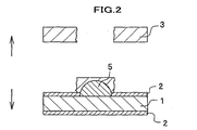
- FIG. 2 is a diagrammatic sectional view showing a rupture state after performing a tensile test of an iron member-aluminum member joined body formed by joining an iron member and an aluminum member.
- the method for joining an iron member and an aluminum member includes: a first step in which zinc plated layers 2,2 (zinc layers) are formed on both sides (joining side and non-joining side) of a steel sheet 1 (iron member) ; and a second step in which the steel sheet 1 on which the zinc plated layer 2 is formed and an aluminum sheet 3 (aluminum member) are stacked, and resistance welding is performed.
- the zinc plated layers 2,2 containing zinc are formed by, for example, hot dip galvanization.
- the steel sheet 1 a mild steel sheet, a high-tensile strength steel sheet (e.g., a 590 MPa grade high-tensile strength steel sheet and a 780 MPa grade high-tensile strength steel sheet) and the like can be used.
- each zinc plated layer 2 be 45.0-100.0 % by mass. As long as the zinc content falls in this range, any element other than zinc (e.g., Al, Mg and Fe) may be contained in each zinc plated layer 2.
- the zinc plated layer 2 may have a high zinc content and be composed mainly of zinc, or have a low zinc content (though the zinc content should be 45 % by mass or more).
- the amount of the zinc plated layer 2 formed on one side of the steel sheet 1 there is no specific limitation.
- the amount is preferably 5 - 250 g/m 2 .
- the zinc plated layer 2 is formed not on the aluminum sheet 3 but only on the steel sheet 1, aluminum can be easily recycled.
- the steel sheet 1 having the zinc plated layer 2 formed thereon by hot-dip plating may be referred to as "hot dip galvanized steel sheet”; the steel sheet 1 having the zinc plated layer 2 formed thereon by hot-dip plating and alloyed by heat treatment may be referred to as “alloyed-galvanized steel sheet”; and the steel sheet 1 having the zinc plated layer 2 formed thereon by electroplating may be referred to as "electrogalvanized steel sheet”.
- the zinc plated layer 2 composed mainly of zinc and aluminum may be referred to as "Al-Zn plated steel sheet", and the zinc plated layer 2 composed mainly of zinc, aluminum and magnesium may be referred to as "Zn-Al-Mg plated steel sheet”.
- the steel sheet 1 having the zinc plated layer 2 formed on the joining side and the aluminum sheet 3 are stacked in such a manner that the zinc plated layer 2 is sandwiched therebetween, and resistance welding is performed on the stacked portion.
- resistance welding of the stacked portion is performed by spot welding using a pair of electrodes 4,4.
- the aluminum sheet 3 will be described below.
- the aluminum sheet 3 is an aluminum alloy sheet composed mainly of aluminum. It is preferable that the aluminum sheet 3 contain magnesium. The reason is that resistance welding forms a nugget 5 (joined portion) in the aluminum sheet 3, including an intermetallic compound (Al-Zn-Mg) with magnesium and aluminum in the aluminum sheet 3 with zinc, which enhances a welding strength (joining strength) (see FIG. 1 (c)).
- a magnesium content of the aluminum sheet 3 be 0.2 - 10.0 % by mass.
- the magnesium content is less than 0.2 % by mass, an amount of magnesium that can form the above-mentioned intermetallic compound is too small, and a joining strength becomes low.
- the magnesium content is above 10 % by mass, stress corrosion cracks and the like may occur on the aluminum sheet 3 (aluminum matrix), thus the aluminum sheet 3 becomes not suitable for structure member.
- the steel sheet 1 having the zinc plated layers 2,2 formed thereon and the aluminum sheet 3 are stacked in such a manner that the zinc plated layer 2 on the joining side is sandwiched therebetween, and a stacked state is retained by, for example, jigs.
- the stacked portion is pinched by the electrodes 4,4 with a specific pressure, and a cycle of a specific current application is repeated at a specific number.
- the molten zinc diffuses in the aluminum sheet 3.
- the diffused zinc forms the nugget 5 (joining portion) including an intermetallic compound (Al-Zn-Mg) with aluminum and magnesium which are partially molten in the aluminum sheet 3.
- a steel sheet-aluminum sheet joined body 6 (iron member-aluminum member joined body) can be obtained in which the steel sheet 1 (iron member) and the aluminum sheet 3 (aluminum member) are excellently welded (joined).
- the steel sheet-aluminum sheet joined body 6 is formed of the steel sheet 1 and the aluminum sheet 3 joined together. Therefore, for example, it is remarkably lighter than a joined body formed of steel sheets 1 joined together.
- the steel sheet 1 and the aluminum sheet 3 are strongly joined through the nugget 5 in a form of intermetallic compound Al-Zn-Mg.
- the steel sheet 1 is not simply detached from the aluminum sheet 3; instead, as shown in FIG. 2, the aluminum sheet 3 positioned outside the nugget 5 will be partially ruptured and the steel sheet-aluminum sheet joined body 6 (see FIG. 1) will be broken. This may be because joining of the nugget 5 and the steel sheet 1, as well as joining of the nugget 5 and the aluminum sheet 3, is extremely strong, and thus drawing the members away from each other will rupture the aluminum sheet 3 which has the lowest mechanical strength.
- the iron member-aluminum member joined body which is light and formed of the steel sheet 1 and the aluminum sheet 3 joined together with a high strength, is applicable to a variety of fields.
- the iron member-aluminum member joined body can be suitably used as a panel to be joined to a main frame of a vehicle body.
- the steel sheet 1 and the aluminum sheet 3 are joined by one type of resistance welding, i.e., spot welding.
- resistance welding i.e., spot welding
- seam welding or projection welding may be used as resistance welding.
- the welding is not limited to resistance welding, and other weldings, such as laser welding, electron beam welding and arc welding, may be used.
- the zinc plated layer 2 (zinc layer) is formed by hot dip galvanization.
- a method for forming the zinc layer is not limited to this embodiment, and the zinc layer may be formed by electrical method (electrodeposition), coating, spraying and the like.
- the zinc plated layer 2 (zinc layer) is formed on both sides (joining side and non-joining side) of the steel sheet 1 (iron member).
- the zinc plated layer 2 may be formed on at least a joining side of one of the steel sheet 1 and the aluminum sheet 3 (aluminum member).
- a mild steel sheet having a thickness of 1.0 mm was prepared, and on both sides (joining side and non-joining side) thereof, the zinc plated layers 2,2 each having a thickness of 10.0 ⁇ m were formed by hot dip galvanization, to thereby obtain a hot dip galvanized steel sheet.
- a composition of the zinc plated layer 2 was 99.5 % by mass of zinc and 0.5 % by mass of aluminum.
- the hot dip galvanized steel sheet and a 6,000 series aluminum sheet 3 having a thickness of 1.0 mm containing 0.5 % by mass of magnesium and 1.0 % by mass of silicon were partially stacked, and resistance welding was performed by spot welding.
- Example 3 Substantially the same procedure was repeated as in Example 1, except that a 5,000 series containing 2.5 % by mass of magnesium and 0.17 % by mass of silicon was used as the aluminum sheet 3. (1-3) Example 3
- Example 3 Substantially the same procedure was repeated as in Example 1, except that a 5,000 series containing 4.5 % by mass of magnesium and 0.12 % by mass of silicon was used as the aluminum sheet 3.
- Example 4-9 an alloyed-galvanized steel sheet having a zinc plated layer 2 with a thickness of 5.0 ⁇ m formed thereon and the aluminum sheet 3 with a different magnesium content were joined in the same manner as in Example 1, and a joining strength was measured.
- a mild steel sheet was used as the steel sheet 1, and on both sides thereof, zinc plated layers were formed by hot dip galvanization and then alloyed by heat treatment, to thereby obtain an alloyed-galvanized steel sheet having zinc plated layers 2, 2 with thickness of 5.0 ⁇ m formed thereon.
- a composition of the zinc plated layer 2 was 90 % by mass of zinc, 0.2 % by mass of aluminum and 9.8 % by mass of iron.
- Example 4 Substantially the same procedure was repeated as in Example 4, except that a 5,000 series containing 4. 5 % by mass of magnesium and 0.12% by mass of silicon was used as the aluminum sheet 3.
- Example 4 Substantially the same procedure was repeated as in Example 4, except that a 590 MPa grade high-tensile strength steel sheet was used as the steel sheet 1.
- Example 5 Substantially the same procedure was repeated as in Example 5, except that a 590 MPa grade high-tensile strength steel sheet was used as the steel sheet 1.
- Example 4 Substantially the same procedure was repeated as in Example 4, except that a 780 MPa grade high-tensile strength steel sheet was used as the steel sheet 1.
- Example 5 Substantially the same procedure was repeated as in Example 5, except that a 780 MPa grade high-tensile strength steel sheet was used as the steel sheet 1.
- Example 2 Substantially the same procedure was repeated as in Example 1, except that a zinc plated layer 2 having a thickness of 3.0 ⁇ m was formed by electroplating. A composition of the zinc plated layer 2 was 100% by mass of zinc. Results of joining strength measurement are shown in Table 1 and FIG. 3, together with various properties and welding conditions of the electrogalvanized steel sheet and the aluminum sheet 3.
- Example 3 Substantially the same procedure was repeated as in Example 3, except that a zinc plated layer 2 having a thickness of 3.0 ⁇ m was formed by electroplating. A composition of the zinc plated layer 2 was 100% by mass of zinc.
- Example 2 Substantially the same procedure was repeated as in Example 1, except that a zinc plated layer 2 having a zinc content of 45 % by mass and an aluminum content of 55 % by mass was formed by hot dip galvanization. Results of joining strength measurement are shown in Table 1 and FIG. 3, together with various properties and welding conditions of the Al-Zn plated steel sheet and the aluminum sheet 3.
- Example 3 Substantially the same procedure was repeated as in Example 3, except that a zinc plated layer 2 having a zinc content of 45 % by mass and an aluminum content of 55 % by mass was formed by hot dip galvanization.
- Example 14 a Zn-Al-Mg plated steel sheet on which a zinc plated layer 2 having a thickness of 10 ⁇ m including aluminum and iron in addition to zinc as a main component was formed thereon, and an aluminum sheet 3 with a different magnesium content were joined in the same manner as in Example 1, and a joining strength was measured.
- Example 2 Substantially the same procedure was repeated as in Example 1, except that a zinc plated layer 2 having a zinc content of 85.8 % by mass, an aluminum content of 11.0 % by mass and a magnesium content of 3.0 % by mass was formed by hot dip galvanization. Results of joining strength measurement are shown in Table 1 and FIG. 3, together with various properties and welding conditions of the Zn-Al-Mg plated steel sheet and the aluminum sheet 3.
- Example 3 Substantially the same procedure was repeated as in Example 3, except that a zinc plated layer 2 having a zinc content of 85. 8 % by mass, a aluminum content of 11.0 % by mass and a magnesium content of 3.0 % by mass was formed by hot dip galvanization.
- Example 2 Substantially the same procedure was repeated as in Example 1, except that the steel sheet 1 and the aluminum sheet 3 were joined without forming zinc plated layers 2,2.
Landscapes
- Engineering & Computer Science (AREA)
- Mechanical Engineering (AREA)
- Physics & Mathematics (AREA)
- Optics & Photonics (AREA)
- Plasma & Fusion (AREA)
- Resistance Welding (AREA)
- Arc Welding In General (AREA)
- Laser Beam Processing (AREA)
- Welding Or Cutting Using Electron Beams (AREA)
Abstract
There is provided a method for excellently joining an iron member and an aluminum member. A steel sheet (1) composed mainly of iron and an aluminum sheet (3) composed mainly of aluminum are joined, wherein the steel sheet (1) has a zinc-containing zinc plated layer (2) formed on a joining side, and the steel sheet (1) and the aluminum sheet (3) are partially stacked and spot-welded while the zinc plated layer (2) is sandwiched therebetween.

Description
- The present invention relates to a method for joining an iron member and an aluminum member.
- Conventionally, for a body of a vehicle, such as automobile, steel sheet or the like has been used. On the other hand, weight reduction of the vehicle body has been demanded from a viewpoint of reducing fuel consumption. Therefore, it has been demanded to develop a technique of joining dissimilar materials, such as a steel sheet or the like and a light aluminum alloy sheet or the like, which may be applicable as a part of the vehicle body.
- For such a joining of a steel sheet and an aluminum alloy sheet, proposals have been made, such as "joined body of dissimilar materials and method for resistance spot welding" (see
Japanese Unexamined Patent Publication Kokai No. 2003-145278 Japanese Unexamined Patent Publication Kokai No. H09-155561 - In addition to the techniques disclosed in the above-mentioned patent documents, a method for further excellently joining an iron member and an aluminum member has been demanded.
- Therefore, an object of the present invention is to provide a method for excellently joining an iron member and an aluminum member.
- As a means for solving the above-mentioned problems, one aspect of the present invention provides a method for joining an iron member composed mainly of iron and an aluminum member composed mainly of aluminum, including steps of: forming a zinc layer on a joining side of at least one of the iron member and the aluminum member, partially stacking the iron member and the aluminum member with the zinc layer being sandwiched therebetween, and welding them together.
- According to this method for joining an iron member and an aluminum member, at least one of the iron member and the aluminum member has a zinc layer formed on a joining side and the iron member and the aluminum member are welded while the zinc layer is sandwiched therebetween. Upon the welding, a part of zinc having a lower melting point and a part of aluminum are easily molten by heat of welding, and a part of the molten zinc diffuses in the aluminum member. Then, the part of the molten zinc diffused in the aluminum member is hardened, and thus the iron member and the aluminum member are excellently welded.
- In addition, in the method for joining an iron member and an aluminum member according to the present invention, the aluminum member may contain magnesium.
- According to such a method for joining an iron member and an aluminum member, a joining strength between the iron member and the aluminum member is enhanced since the aluminum member contains magnesium.
- In addition, in the method for joining an iron member and an aluminum member according to the present invention, the welding may be at least one of resistance welding, laser welding, electron beam welding and arc welding.
- According to such a method for joining an iron member and an aluminum member, the iron member and the aluminum member are suitably welded by at least one of resistance welding, laser welding, electron beam welding and arc welding.
- Examples of the resistance welding include spot welding, seam welding and projection welding.
- As shown above, the present invention provides a method for joining an iron member and an aluminum member wherein the iron member and the aluminum member are excellently welded.
- The various aspects, other advantages and further features of the present invention will become more apparent by describing in detail illustrative, non-limiting embodiments thereof with reference to the accompanying drawings.
-
- FIG. 1 shows cross sectional views stepwise explaining a method for joining an iron member and an aluminum member according to one embodiment of the present invention: (a) shows a state before stacking a steel sheet and an aluminum sheet; (b) shows a state in which the steel sheet and the aluminum sheet are stacked and welded; and (c) shows a state after welding.
- FIG. 2 is a diagrammatic sectional view showing a rupture state after performing a tensile test of an iron member-aluminum member joined body formed by joining an iron member and an aluminum member.
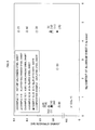
- FIG. 3 is a graph showing relationships between magnesium content and joining strength of aluminum sheets in Examples 1 - 15.
-
- 1
- Steel sheet (iron member)
- 2
- Zinc plated layer (zinc layer)
- 3
- Aluminum sheet (aluminum member)
- 4
- Electrode
- 5
- Nugget
- 6
- Steel sheet-aluminum sheet joined body
- Next, an embodiment of the present invention will be descried with reference to FIGs. 1 and 2.
- FIG. 1 shows cross sectional views stepwise explaining a method for joining an iron member and an aluminum member according to one embodiment of the present invention: (a) shows a state before stacking a steel sheet and an aluminum sheet; (b) shows a state in which the steel sheet and the aluminum sheet are stacked and welded; and (c) shows a state after welding. FIG. 2 is a diagrammatic sectional view showing a rupture state after performing a tensile test of an iron member-aluminum member joined body formed by joining an iron member and an aluminum member.
- Referring to FIG. 1, the method for joining an iron member and an aluminum member according to the present embodiment includes: a first step in which zinc plated
layers 2,2 (zinc layers) are formed on both sides (joining side and non-joining side) of a steel sheet 1 (iron member) ; and a second step in which thesteel sheet 1 on which the zinc platedlayer 2 is formed and an aluminum sheet 3 (aluminum member) are stacked, and resistance welding is performed. - As shown in FIG. 1(a), on both sides of the
steel sheet 1 composed mainly of iron, the zinc platedlayers steel sheet 1, a mild steel sheet, a high-tensile strength steel sheet (e.g., a 590 MPa grade high-tensile strength steel sheet and a 780 MPa grade high-tensile strength steel sheet) and the like can be used. - As a method for forming the zinc plated
layer 2 on thesteel sheet 1, hot-dip plating, electroplating and the like can be used. - It is preferable that a zinc content of each zinc plated
layer 2 be 45.0-100.0 % by mass. As long as the zinc content falls in this range, any element other than zinc (e.g., Al, Mg and Fe) may be contained in each zinc platedlayer 2. In other words, the zinc platedlayer 2 may have a high zinc content and be composed mainly of zinc, or have a low zinc content (though the zinc content should be 45 % by mass or more). - In the present invention, with respect to an amount of the zinc plated
layer 2 formed on one side of thesteel sheet 1, there is no specific limitation. However, the amount is preferably 5 - 250 g/m2. - In addition, since the zinc plated
layer 2 is formed not on thealuminum sheet 3 but only on thesteel sheet 1, aluminum can be easily recycled. - With respect to the
steel sheet 1 having the zinc platedlayer 2 formed thereon, hereinafter, thesteel sheet 1 having the zinc platedlayer 2 formed thereon by hot-dip plating may be referred to as "hot dip galvanized steel sheet"; thesteel sheet 1 having the zinc platedlayer 2 formed thereon by hot-dip plating and alloyed by heat treatment may be referred to as "alloyed-galvanized steel sheet"; and thesteel sheet 1 having the zinc platedlayer 2 formed thereon by electroplating may be referred to as "electrogalvanized steel sheet". - Depending on the composition of the zinc plated
layer 2, for example, the zinc platedlayer 2 composed mainly of zinc and aluminum may be referred to as "Al-Zn plated steel sheet", and the zinc platedlayer 2 composed mainly of zinc, aluminum and magnesium may be referred to as "Zn-Al-Mg plated steel sheet". - Next, as shown in FIG. 1(b), the
steel sheet 1 having the zinc platedlayer 2 formed on the joining side and thealuminum sheet 3 are stacked in such a manner that the zinc platedlayer 2 is sandwiched therebetween, and resistance welding is performed on the stacked portion. Hereinbelow, description is made regarding a case where resistance welding of the stacked portion is performed by spot welding using a pair ofelectrodes - The
aluminum sheet 3 will be described below. - The
aluminum sheet 3 is an aluminum alloy sheet composed mainly of aluminum. It is preferable that thealuminum sheet 3 contain magnesium. The reason is that resistance welding forms a nugget 5 (joined portion) in thealuminum sheet 3, including an intermetallic compound (Al-Zn-Mg) with magnesium and aluminum in thealuminum sheet 3 with zinc, which enhances a welding strength (joining strength) (see FIG. 1 (c)). - It is preferable that a magnesium content of the
aluminum sheet 3 be 0.2 - 10.0 % by mass. When the magnesium content is less than 0.2 % by mass, an amount of magnesium that can form the above-mentioned intermetallic compound is too small, and a joining strength becomes low. On the other hand, when the magnesium content is above 10 % by mass, stress corrosion cracks and the like may occur on the aluminum sheet 3 (aluminum matrix), thus thealuminum sheet 3 becomes not suitable for structure member. - Subsequently, the
steel sheet 1 having the zinc platedlayers aluminum sheet 3 are stacked in such a manner that the zinc platedlayer 2 on the joining side is sandwiched therebetween, and a stacked state is retained by, for example, jigs. Next, from both outer sides thereof, the stacked portion is pinched by theelectrodes - With this current application, zinc having a lower melting point in the zinc plated
layer 2 is preferentially molten, and the molten zinc diffuses in thealuminum sheet 3. The diffused zinc forms the nugget 5 (joining portion) including an intermetallic compound (Al-Zn-Mg) with aluminum and magnesium which are partially molten in thealuminum sheet 3. - In this current application, a melting point of zinc (approximately 420 °C) and a melting point of zinc-aluminum alloy (for example, 380 °C for Zn-Al alloy with a composition of Zn:Al = 89-97: 11-3) are low, and the
steel sheet 1 and thealuminum sheet 3 can be excellently joined without applying a high current by a high voltage. - In other words, elution of the molten aluminum and the like to an electrode 4-side can be prevented since a high current is not applied and welding can be performed at a lower temperature. As a result, aluminum and electrode can be prevented from becoming alloy, which enhances durability of the electrode and continuous weldability.
- After repeating a specific number of current application cycles, current application is terminated. Temperatures of the
steel sheet 1 and thealuminum sheet 3 drop, which allows zinc diffused in thealuminum sheet 3 to be age-hardened. At the same time, temperature of thenugget 5 also drops due to termination of current application, and a strength of thenugget 5, i.e., welding strength (joining strength) between thesteel sheet 1 and thealuminum sheet 3 can be enhanced. - As described above, a steel sheet-aluminum sheet joined body 6 (iron member-aluminum member joined body) can be obtained in which the steel sheet 1 (iron member) and the aluminum sheet 3 (aluminum member) are excellently welded (joined).
- Thus obtained steel sheet-aluminum sheet joined
body 6 will be described below. The steel sheet-aluminum sheet joinedbody 6 is formed of thesteel sheet 1 and thealuminum sheet 3 joined together. Therefore, for example, it is remarkably lighter than a joined body formed ofsteel sheets 1 joined together. - In addition, as described above, in the steel sheet-aluminum sheet joined
body 6, thesteel sheet 1 and thealuminum sheet 3 are strongly joined through thenugget 5 in a form of intermetallic compound Al-Zn-Mg. When a tensile test is performed on the steel sheet-aluminum sheet joinedbody 6 for measuring a joining strength, thesteel sheet 1 is not simply detached from thealuminum sheet 3; instead, as shown in FIG. 2, thealuminum sheet 3 positioned outside thenugget 5 will be partially ruptured and the steel sheet-aluminum sheet joined body 6 (see FIG. 1) will be broken. This may be because joining of thenugget 5 and thesteel sheet 1, as well as joining of thenugget 5 and thealuminum sheet 3, is extremely strong, and thus drawing the members away from each other will rupture thealuminum sheet 3 which has the lowest mechanical strength. - As described above, the iron member-aluminum member joined body, which is light and formed of the
steel sheet 1 and thealuminum sheet 3 joined together with a high strength, is applicable to a variety of fields. For example, in a filed of automobile, the iron member-aluminum member joined body can be suitably used as a panel to be joined to a main frame of a vehicle body. - One embodiment of the present invention has been described above. However, the present invention should not be limited to the above embodiment, and it is a matter of course that the above embodiment may properly be modified without departing from the scope of the present invention.
- For example, in the embodiment above, the
steel sheet 1 and thealuminum sheet 3 are joined by one type of resistance welding, i.e., spot welding. However, seam welding or projection welding may be used as resistance welding. - Moreover, the welding is not limited to resistance welding, and other weldings, such as laser welding, electron beam welding and arc welding, may be used.
- In the laser welding it is desirable that, at the stacked portion of the
steel sheet 1 and thealuminum sheet 3, laser beam be irradiated on the steel sheet 1 (iron member) to directly heat thesteel sheet 1, and thealuminum sheet 3 be partially molten by residual heat. This is because laser beam reflect diffusely and a large amount of energy will be lost, if laser beam is irradiated on thealuminum sheet 3. - In the above-mentioned embodiment, the zinc plated layer 2 (zinc layer) is formed by hot dip galvanization. However, a method for forming the zinc layer is not limited to this embodiment, and the zinc layer may be formed by electrical method (electrodeposition), coating, spraying and the like.
- In the above-mentioned embodiment, the zinc plated layer 2 (zinc layer) is formed on both sides (joining side and non-joining side) of the steel sheet 1 (iron member). However, the zinc plated
layer 2 may be formed on at least a joining side of one of thesteel sheet 1 and the aluminum sheet 3 (aluminum member). - The present invention will be described in more detail with reference to Examples.
- In each of Examples 1-3, a hot dip galvanized steel sheet having a zinc plated
layer 2 with a thickness of 10.0 µm formed thereon and thealuminum sheet 3 with a different magnesium content were joined, and a joining strength was measured. - As a
steel sheet 1, a mild steel sheet having a thickness of 1.0 mm was prepared, and on both sides (joining side and non-joining side) thereof, the zinc platedlayers layer 2 was 99.5 % by mass of zinc and 0.5 % by mass of aluminum. - Then, the hot dip galvanized steel sheet and a 6,000
series aluminum sheet 3 having a thickness of 1.0 mm containing 0.5 % by mass of magnesium and 1.0 % by mass of silicon were partially stacked, and resistance welding was performed by spot welding. - For spot welding, a stacked portion of the
steel sheet 1 and thealuminum sheet 3 was pinched by theelectrodes 4 each having a diameter of a contact part of 6 mm, with 1.47 kN (150 kgf), and a cycle of applying a current of 14 kA was repeated for 18 times. (1-1-2) Measurement of joining strength - In conformity with JIS Z3136 "Specimen dimensions and procedure for shear testing resistance spot and embossed projection welded joints", a tensile test was performed on the steel sheet-aluminum sheet joined
body 6 of Example 1, and a joining strength (rupture strength) was measured. A result of measurement is shown in Table 1 and FIG. 3, together with various properties and welding conditions of the hot dip galvanized steel sheet and thealuminum sheet 3. In FIG. 3, " (1) " indicates the result of Example 1. Other referential numbers indicate their respective Examples. - Substantially the same procedure was repeated as in Example 1, except that a 5,000 series containing 2.5 % by mass of magnesium and 0.17 % by mass of silicon was used as the
aluminum sheet 3. (1-3) Example 3 - Substantially the same procedure was repeated as in Example 1, except that a 5,000 series containing 4.5 % by mass of magnesium and 0.12 % by mass of silicon was used as the
aluminum sheet 3. - In each of Examples 4-9, an alloyed-galvanized steel sheet having a zinc plated
layer 2 with a thickness of 5.0 µm formed thereon and thealuminum sheet 3 with a different magnesium content were joined in the same manner as in Example 1, and a joining strength was measured. - A mild steel sheet was used as the
steel sheet 1, and on both sides thereof, zinc plated layers were formed by hot dip galvanization and then alloyed by heat treatment, to thereby obtain an alloyed-galvanized steel sheet having zinc platedlayers layer 2 was 90 % by mass of zinc, 0.2 % by mass of aluminum and 9.8 % by mass of iron. - Then, the alloyed-galvanized steel sheet and a 6,000
series aluminum sheet 3 containing 0.5% by mass of magnesium and 1.0 % by mass of silicon were joined, and a joining strength was measured. Results of measurement are shown in Table 1 and FIG. 3, together with various properties and welding conditions of the alloyed-galvanized steel sheet and thealuminum sheet 3. - Substantially the same procedure was repeated as in Example 4, except that a 5,000 series containing 4. 5 % by mass of magnesium and 0.12% by mass of silicon was used as the
aluminum sheet 3. - Substantially the same procedure was repeated as in Example 4, except that a 590 MPa grade high-tensile strength steel sheet was used as the
steel sheet 1. - Substantially the same procedure was repeated as in Example 5, except that a 590 MPa grade high-tensile strength steel sheet was used as the
steel sheet 1. - Substantially the same procedure was repeated as in Example 4, except that a 780 MPa grade high-tensile strength steel sheet was used as the
steel sheet 1. - Substantially the same procedure was repeated as in Example 5, except that a 780 MPa grade high-tensile strength steel sheet was used as the
steel sheet 1. - In each of Examples 10 and 11, an electrogalvanized steel sheet having a zinc plated
layer 2 with a thickness of 3.0 µm formed thereon and analuminum sheet 3 with a different magnesium content were joined in the same manner as in Example 1, and a joining strength was measured. - Substantially the same procedure was repeated as in Example 1, except that a zinc plated
layer 2 having a thickness of 3.0 µm was formed by electroplating. A composition of the zinc platedlayer 2 was 100% by mass of zinc. Results of joining strength measurement are shown in Table 1 and FIG. 3, together with various properties and welding conditions of the electrogalvanized steel sheet and thealuminum sheet 3. - Substantially the same procedure was repeated as in Example 3, except that a zinc plated
layer 2 having a thickness of 3.0 µm was formed by electroplating. A composition of the zinc platedlayer 2 was 100% by mass of zinc. - In each of Examples 12 and 13, an Al-Zn plated steel sheet having a zinc plated
layer 2 with a thickness of 10 µm with a low zinc content and a high aluminum content formed thereon and analuminum sheet 3 with a different magnesium content were joined in the same manner as in Example 1, and a joining strength was measured. - Substantially the same procedure was repeated as in Example 1, except that a zinc plated
layer 2 having a zinc content of 45 % by mass and an aluminum content of 55 % by mass was formed by hot dip galvanization. Results of joining strength measurement are shown in Table 1 and FIG. 3, together with various properties and welding conditions of the Al-Zn plated steel sheet and thealuminum sheet 3. - Substantially the same procedure was repeated as in Example 3, except that a zinc plated
layer 2 having a zinc content of 45 % by mass and an aluminum content of 55 % by mass was formed by hot dip galvanization. - In each of Examples 14 and 15, a Zn-Al-Mg plated steel sheet on which a zinc plated
layer 2 having a thickness of 10 µm including aluminum and iron in addition to zinc as a main component was formed thereon, and analuminum sheet 3 with a different magnesium content were joined in the same manner as in Example 1, and a joining strength was measured. - Substantially the same procedure was repeated as in Example 1, except that a zinc plated
layer 2 having a zinc content of 85.8 % by mass, an aluminum content of 11.0 % by mass and a magnesium content of 3.0 % by mass was formed by hot dip galvanization. Results of joining strength measurement are shown in Table 1 and FIG. 3, together with various properties and welding conditions of the Zn-Al-Mg plated steel sheet and thealuminum sheet 3. - Substantially the same procedure was repeated as in Example 3, except that a zinc plated
layer 2 having a zinc content of 85. 8 % by mass, a aluminum content of 11.0 % by mass and a magnesium content of 3.0 % by mass was formed by hot dip galvanization. - Substantially the same procedure was repeated as in Example 1, except that the
steel sheet 1 and thealuminum sheet 3 were joined without forming zinc platedlayers Table 1 Ex 1Ex 2Ex 3Ex 4Ex 5Ex 6Ex7 Ex 8 Ex 9 Ex 10Ex 11Ex 12Ex 13Ex 14Ex 15Comparative Ex 1Object to be welded · Steel sheet Type of steel sheet Hot dip galvanized steel sheet Alloyed-galvanized steel sheet Electrogalvanized steel sheet Al-Zn plated steel sheet n-Al-Mg sheet Unplated steel sheet Steel type Mild steel sheet 590MPa grade high-tensile strength steel sheet 780MPa grade high-tensile strength steel sheet Mild steel sheet Thickness(mm) 1 1 1 1 1 1 1 1 1 1 1 1 1 1 1 1 Zn plated layer (µm) 10 10 10 5 5 5 5 5 5 5 3 10 10 10 10 - Zn plated layer composition Zn(%bymass) 99.5 99.5 99.5 90 90 90 90 90 90 100 100 45 45 85.8 85.8 - Al (% by mass) 0.5 0.5 0.5 0.2 0.2 0.2 0.2 0.2 0.2 - - 55 55 11 11 - Mg (% by mass) - - - - - - - - - - - - - 3 3 - Fre (% by mass) - - - 9.8 9.8 9.8 9.8 9.8 9:8 - - - - - - - · Aluminum sheet Thickness (mm) 1 I 1 1 1 1 1 1 1 1 1 1 1 1 1 1 Alloy type AA 6022 A 5052 A 5182 AA 6022 A 5182 AA 6022 A 5182 AA 6022 A 5182 AA 6022 A 5182 AA 6022 A 5182 AA 6022 A 5182 AA 6022 Mg content (% by mass) 0.5 2.5 4.5 0.5 4.5 0.5 4.5 0.5 4.5 0.5 4.5 0.5 4.5 0.5 4.5 0.5 Si content (% by mass) 1.0 0.17 0.12 1.0 0.12 2 1.0 0.12 1.0 0.12 1.0 0.12 1.0 0.12 1.0 0.12 1.0 Welding conditions Electrode diameter (mm) 6 6 6 6 6 6 6 6 6 6 6 6 6 6 6 6 Pinching force of Electrode (kN(kgf)) 1.47 (150) 1.47 (150) 1.47 (150) 1.47 (150) 1.47 (150) 1.47 (150) 1.47 (150) 1.47 (150) 1.47 (150) 1.47 (150) 1.47 (150) 1.47 (150) 1.47 (150) 1.47 (150) 1.47 (150) 1.47 (150) Current(kA) 14 14 14 14 14 14 14 14 14 14 14 14 14 14 14 14 Current application cycle 18 18 18 18 18 18 18 18 18 18 18 18 18 18 18 18 Evaluation after welding Joining strength (kN(kgf)) 3.15 (321) 2.84 (290) 3.63 (370) 3.32 (338) 3.13 (320) 3.38 (344) 4.33 (441) 2.78 (283) 4.01(409) 3.05 (311) 3.03 (310) 3.17 (323) 3.08 (314) 3.06 (312) 2.84 (291) 0-0.3 (30) - As is apparent from Table 1 and FIG. 3, a joining strength of the steel sheet-aluminum sheet joined
body 6 in each of Examples 1 - 15 is remarkably enhanced (more than 10 times) as compared with the case of Comparative Example 1 which does not exhibit a sufficient joining strength as a joined structure. Therefore, it proves that the method for joining an iron member and an aluminum member according to the present invention is suitable for excellently joining thesteel sheet 1 and thealuminum sheet 3. - It also proves that, even when the zinc content of the zinc plated
layer 2 is low (45 % by mass), an excellent joining strength is obtained (Examples 12 and 13).
Claims (3)
- A method for joining an iron member composed mainly of iron and an aluminum member composed mainly of aluminum, comprising steps of:forming a zinc layer on a joining side of at least one of the iron member and the aluminum member,partially stacking the iron member and the aluminum member with the zinc layer being sandwiched therebetween, andwelding them together.
- The method for joining iron member and aluminum member according to Claim 1, wherein the aluminum member contains magnesium.
- The method for joining iron member and aluminum member according to Claim 1 or 2, wherein the welding is at least one of resistance welding, laser welding, electron beam welding and arc welding.
Applications Claiming Priority (2)
| Application Number | Priority Date | Filing Date | Title |
|---|---|---|---|
| JP2004311188 | 2004-10-26 | ||
| PCT/JP2005/019703 WO2006046608A1 (en) | 2004-10-26 | 2005-10-26 | Method for bonding iron-based member with aluminum-based member |
Publications (2)
| Publication Number | Publication Date |
|---|---|
| EP1806200A1 true EP1806200A1 (en) | 2007-07-11 |
| EP1806200A4 EP1806200A4 (en) | 2008-01-02 |
Family
ID=36227850
Family Applications (1)
| Application Number | Title | Priority Date | Filing Date |
|---|---|---|---|
| EP05805325A Withdrawn EP1806200A4 (en) | 2004-10-26 | 2005-10-26 | Method for bonding iron-based member with aluminum-based member |
Country Status (6)
| Country | Link |
|---|---|
| US (1) | US20090050608A1 (en) |
| EP (1) | EP1806200A4 (en) |
| JP (1) | JPWO2006046608A1 (en) |
| KR (1) | KR20070058712A (en) |
| CN (1) | CN101043968A (en) |
| WO (1) | WO2006046608A1 (en) |
Cited By (15)
| Publication number | Priority date | Publication date | Assignee | Title |
|---|---|---|---|---|
| WO2009022208A1 (en) * | 2007-08-10 | 2009-02-19 | Nissan Motor Co., Ltd. | Bonded structure of dissimilar metallic materials and method of joining dissimilar metallic materials |
| EP2141255A1 (en) | 2008-07-04 | 2010-01-06 | Ford Global Technologies, LLC | Improved corrosion inhibiting structure |
| DE102009002912A1 (en) | 2008-12-03 | 2010-06-10 | Brose Fahrzeugteile Gmbh & Co. Kommanditgesellschaft, Coburg | Vehicle seat with a plurality of structural or holding parts and method for producing structural or holding parts of such a vehicle seat |
| EP2281657A4 (en) * | 2008-04-21 | 2011-04-27 | Honda Motor Co Ltd | Joining method for and jointed structure of metal members, and brazing filler metal |
| US7943883B2 (en) | 2006-10-27 | 2011-05-17 | Honda Motor Co., Ltd. | Method for joining iron member and aluminum member and iron-aluminum joined body |
| DE102011077458A1 (en) * | 2011-06-14 | 2012-12-20 | Brose Fahrzeugteile Gmbh & Co. Kommanditgesellschaft, Coburg | Welding components of motor vehicle, comprises providing first component having first connecting portion, second component having second material, providing metallic coating on first connecting portion, welding first and second components |
| DE102013013175A1 (en) | 2013-08-08 | 2014-03-06 | Daimler Ag | Connecting element useful for connecting first component of first metal material with second component of second metal material, comprises first portion of first metal material and second portion of second metal material |
| WO2014184599A1 (en) * | 2013-05-13 | 2014-11-20 | Arcelormittal Investigación Y Desarrollo Sl | Assembly of an aluminum component and of a steel component having a znalmg alloy coating |
| WO2015149756A2 (en) | 2014-04-02 | 2015-10-08 | Rheinisch Westfälische Technische Hochschule Aachen (Rwth) | Method for producing a bonded joint, and structural element |
| DE102016006035A1 (en) | 2016-05-18 | 2016-12-01 | Daimler Ag | A method of welding a steel component to an aluminum component of an assembly |
| CN110267764A (en) * | 2017-01-30 | 2019-09-20 | 纽弗雷有限公司 | Welding element and welding method for connecting the welding element to a workpiece |
| EP3587614A4 (en) * | 2017-02-22 | 2020-01-01 | Nippon Steel Nisshin Co., Ltd. | LASER BRAZING METHOD AND METHOD FOR PRODUCING COVERED JOINT ELEMENT |
| WO2020208399A1 (en) * | 2019-04-09 | 2020-10-15 | Arcelormittal | Assembly of an aluminium component and of a press hardened steel part having an alloyed coating comprising silicon, iron, zinc, optionally magnesium, the balance being aluminum |
| US10807177B2 (en) | 2017-02-22 | 2020-10-20 | Nippon Steel Nisshin Co., Ltd. | Method for MIG brazing, method for manufacturing lap joint member, and lap joint member |
| RU2788614C1 (en) * | 2019-04-09 | 2023-01-23 | Арселормиттал | Assembly made of an aluminium component and a pressure-tempered steel part with an alloy coating including silicon, iron, zinc, and magnesium, with the remainder being aluminium |
Families Citing this family (35)
| Publication number | Priority date | Publication date | Assignee | Title |
|---|---|---|---|---|
| JP4961530B2 (en) * | 2006-05-12 | 2012-06-27 | 日産自動車株式会社 | Method of joining dissimilar metals by resistance spot welding |
| JP5088920B2 (en) * | 2006-05-19 | 2012-12-05 | 日新製鋼株式会社 | Manufacturing method for building components |
| JP4961532B2 (en) * | 2006-07-25 | 2012-06-27 | 日産自動車株式会社 | Method and apparatus for joining dissimilar metals |
| JP5495093B2 (en) * | 2008-01-17 | 2014-05-21 | 日産自動車株式会社 | Joining method and structure of dissimilar metals |
| KR100969075B1 (en) * | 2008-06-16 | 2010-07-09 | 현대자동차주식회사 | Dissimilar metal joining system and method |
| CN102089114B (en) * | 2008-07-09 | 2015-07-22 | 铃木株式会社 | Laser lap welding method for galvanized steel sheets |
| JP5326862B2 (en) * | 2008-09-08 | 2013-10-30 | 日産自動車株式会社 | Dissimilar metal joining method of magnesium alloy and steel |
| FR2936177B1 (en) * | 2008-09-24 | 2011-08-26 | Air Liquide | LASER WELDING PROCESS OF CO2 TYPE WITH DYNAMIC JET NOZZLE. |
| JP2011140067A (en) * | 2009-12-10 | 2011-07-21 | Kobe Steel Ltd | Process for production of steel plate/aluminum plate joint structure, and steel plate/aluminum plate joint structure produced by the process |
| JP5531623B2 (en) * | 2010-01-08 | 2014-06-25 | スズキ株式会社 | Laser lap welding method of galvanized steel sheet |
| JP5495118B2 (en) | 2010-04-28 | 2014-05-21 | スズキ株式会社 | Laser lap welding method of galvanized steel sheet |
| JP2013027890A (en) * | 2011-07-27 | 2013-02-07 | Mazda Motor Corp | Joint body of aluminum alloy plate material to plated steel plate material |
| CN102848633A (en) * | 2012-02-10 | 2013-01-02 | 王宝根 | Double-sided aluminium multilayer metal composite plate and production line thereof |
| CN102586722A (en) * | 2012-02-10 | 2012-07-18 | 王宝根 | Electric arc spraying multilayer metal composite plate production line |
| CN102529219A (en) * | 2012-02-10 | 2012-07-04 | 王宝根 | Pressure welding production line for multi-layer metal composite plates |
| CN102528286A (en) * | 2012-02-24 | 2012-07-04 | 哈尔滨工业大学 | Welding method for alloy element controlled magnesium/steel |
| JP5832348B2 (en) * | 2012-03-28 | 2015-12-16 | 株式会社Uacj | Aluminum alloy coated plate |
| JP6390047B2 (en) * | 2013-04-12 | 2018-09-19 | 本田技研工業株式会社 | Zinc alloy manufacturing method |
| JP6160190B2 (en) * | 2013-04-15 | 2017-07-12 | マツダ株式会社 | Resistance spot welding method for dissimilar metal materials |
| US10010966B2 (en) * | 2014-02-14 | 2018-07-03 | GM Global Technology Operations LLC | Electrode for resistance spot welding of dissimilar metals |
| WO2015133099A1 (en) * | 2014-03-05 | 2015-09-11 | Jfeスチール株式会社 | Resistive spot-welding method |
| JP6037018B2 (en) * | 2014-03-05 | 2016-11-30 | Jfeスチール株式会社 | Resistance spot welding method |
| US10625367B2 (en) | 2016-04-08 | 2020-04-21 | GM Global Technology Operations LLC | Method of resistance spot welding aluminum to steel |
| US10675703B2 (en) | 2016-04-08 | 2020-06-09 | GM Global Technology Operations LLC | Al-steel weld joint |
| US10786872B2 (en) * | 2017-06-15 | 2020-09-29 | Toyota Jidosha Kabushiki Kaisha | Welding method |
| JP6981275B2 (en) | 2018-01-24 | 2021-12-15 | トヨタ自動車株式会社 | How to join dissimilar metal plates |
| JP6984469B2 (en) | 2018-02-09 | 2021-12-22 | トヨタ自動車株式会社 | How to join dissimilar metal plates |
| CN109048020A (en) * | 2018-09-14 | 2018-12-21 | 上海工程技术大学 | A kind of band pole weldering welding procedure suitable for aluminum steel dissimilar metal |
| WO2020096271A1 (en) * | 2018-11-08 | 2020-05-14 | Renault-Samsung Motors Co., Ltd. | Combination structure of metal sheets for automobile by using trip steel and method for manufacturing the same |
| KR102754548B1 (en) * | 2018-11-08 | 2025-01-14 | 르노코리아 주식회사 | Combination structure of metal sheets for automobile by using TRIP steel and method for manufacturing the same |
| CN111195763A (en) * | 2018-11-19 | 2020-05-26 | 中车唐山机车车辆有限公司 | Welding method of aluminum alloy and stainless steel for vehicle and train vehicle |
| US11583954B2 (en) * | 2019-03-04 | 2023-02-21 | Kabushiki Kaisha Toshiba | Welding method |
| CN110303232B (en) * | 2019-06-13 | 2021-12-17 | 首钢集团有限公司 | Resistance spot welding device of cladding material high-strength steel |
| US11548091B2 (en) | 2019-10-10 | 2023-01-10 | GM Global Technology Operations LLC | Pretreatment of weld flanges to mitigate liquid metal embrittlement cracking in resistance welding of galvanized steels |
| US12551970B2 (en) * | 2022-05-31 | 2026-02-17 | University Of Tennessee Research Foundation | Systems and methods for ultrasonic additive manufacturing of metals |
Family Cites Families (4)
| Publication number | Priority date | Publication date | Assignee | Title |
|---|---|---|---|---|
| JPH04251676A (en) * | 1991-01-28 | 1992-09-08 | Nisshin Steel Co Ltd | Method for resistance welding steel and aluminum material |
| JPH04246182A (en) * | 1991-01-28 | 1992-09-02 | Nisshin Steel Co Ltd | Surface-treated steel sheet excellent in lap resistance weldability |
| JPH0724581A (en) * | 1993-02-03 | 1995-01-27 | Sumitomo Metal Ind Ltd | Resistance welding method for aluminum and steel |
| EP1462207A1 (en) * | 2003-03-29 | 2004-09-29 | Grillo-Werke AG | Welding, soldering or brazing method under a protective atmosphere of metallic workpieces using a Zn/Al filler material |
-
2005
- 2005-10-26 CN CNA2005800356871A patent/CN101043968A/en active Pending
- 2005-10-26 US US11/665,637 patent/US20090050608A1/en not_active Abandoned
- 2005-10-26 EP EP05805325A patent/EP1806200A4/en not_active Withdrawn
- 2005-10-26 KR KR1020077011142A patent/KR20070058712A/en not_active Ceased
- 2005-10-26 JP JP2006543216A patent/JPWO2006046608A1/en not_active Abandoned
- 2005-10-26 WO PCT/JP2005/019703 patent/WO2006046608A1/en not_active Ceased
Cited By (27)
| Publication number | Priority date | Publication date | Assignee | Title |
|---|---|---|---|---|
| US7943883B2 (en) | 2006-10-27 | 2011-05-17 | Honda Motor Co., Ltd. | Method for joining iron member and aluminum member and iron-aluminum joined body |
| WO2009022208A1 (en) * | 2007-08-10 | 2009-02-19 | Nissan Motor Co., Ltd. | Bonded structure of dissimilar metallic materials and method of joining dissimilar metallic materials |
| EP2281657A4 (en) * | 2008-04-21 | 2011-04-27 | Honda Motor Co Ltd | Joining method for and jointed structure of metal members, and brazing filler metal |
| EP2478992A3 (en) * | 2008-04-21 | 2012-11-07 | Honda Motor Co., Ltd. | Method for joining metallic members and brazing filler metal |
| EP2614916A1 (en) * | 2008-04-21 | 2013-07-17 | Honda Motor Co., Ltd. | Method for joining metallic members and brazing filler metal |
| US8492675B2 (en) | 2008-04-21 | 2013-07-23 | Honda Motor Co., Ltd. | Laser welding Al and Fe members with Zn filler |
| EP2141255A1 (en) | 2008-07-04 | 2010-01-06 | Ford Global Technologies, LLC | Improved corrosion inhibiting structure |
| EP2141255B1 (en) * | 2008-07-04 | 2020-03-18 | Volvo Car Corporation | Improved corrosion inhibiting structure |
| DE102009002912A1 (en) | 2008-12-03 | 2010-06-10 | Brose Fahrzeugteile Gmbh & Co. Kommanditgesellschaft, Coburg | Vehicle seat with a plurality of structural or holding parts and method for producing structural or holding parts of such a vehicle seat |
| DE102011077458A1 (en) * | 2011-06-14 | 2012-12-20 | Brose Fahrzeugteile Gmbh & Co. Kommanditgesellschaft, Coburg | Welding components of motor vehicle, comprises providing first component having first connecting portion, second component having second material, providing metallic coating on first connecting portion, welding first and second components |
| WO2014184599A1 (en) * | 2013-05-13 | 2014-11-20 | Arcelormittal Investigación Y Desarrollo Sl | Assembly of an aluminum component and of a steel component having a znalmg alloy coating |
| US11370279B2 (en) | 2013-05-13 | 2022-06-28 | Arcelormittal | Assembly of an aluminum component and of a steel component having a ZnAlMg alloy coating |
| RU2583424C1 (en) * | 2013-05-13 | 2016-05-10 | Арселормиттал | ASSEMBLY OF ALUMINIUM PARTS AND STEEL PARTS WITH COATING FROM ZnAlMg ALLOY |
| DE102013013175A1 (en) | 2013-08-08 | 2014-03-06 | Daimler Ag | Connecting element useful for connecting first component of first metal material with second component of second metal material, comprises first portion of first metal material and second portion of second metal material |
| DE102014104711A1 (en) | 2014-04-02 | 2015-10-08 | RWTH Aachen - Körperschaft des öffentlichen Rechts | Method for producing a cohesive joint connection and structural element |
| WO2015149756A2 (en) | 2014-04-02 | 2015-10-08 | Rheinisch Westfälische Technische Hochschule Aachen (Rwth) | Method for producing a bonded joint, and structural element |
| DE102016006035A1 (en) | 2016-05-18 | 2016-12-01 | Daimler Ag | A method of welding a steel component to an aluminum component of an assembly |
| CN110267764A (en) * | 2017-01-30 | 2019-09-20 | 纽弗雷有限公司 | Welding element and welding method for connecting the welding element to a workpiece |
| US11517973B2 (en) | 2017-01-30 | 2022-12-06 | Newfrey Llc | Welding element and welding method for connecting a weld element to a workpiece |
| EP3587614A4 (en) * | 2017-02-22 | 2020-01-01 | Nippon Steel Nisshin Co., Ltd. | LASER BRAZING METHOD AND METHOD FOR PRODUCING COVERED JOINT ELEMENT |
| US10792746B2 (en) | 2017-02-22 | 2020-10-06 | Nippon Steel Nisshin Co., Ltd. | Laser brazing method and production method for lap joint member |
| US10807177B2 (en) | 2017-02-22 | 2020-10-20 | Nippon Steel Nisshin Co., Ltd. | Method for MIG brazing, method for manufacturing lap joint member, and lap joint member |
| WO2020208399A1 (en) * | 2019-04-09 | 2020-10-15 | Arcelormittal | Assembly of an aluminium component and of a press hardened steel part having an alloyed coating comprising silicon, iron, zinc, optionally magnesium, the balance being aluminum |
| WO2020208489A1 (en) * | 2019-04-09 | 2020-10-15 | Arcelormittal | Assembly of an aluminium component and of a press hardened steel part having an alloyed coating comprising silicon, iron, zinc and magnesium, the balance being aluminum |
| CN113646453A (en) * | 2019-04-09 | 2021-11-12 | 安赛乐米塔尔公司 | Assembly of an aluminium component and a press hardened steel part with an alloy coating comprising silicon, iron, zinc and magnesium, the balance being aluminium |
| RU2788614C1 (en) * | 2019-04-09 | 2023-01-23 | Арселормиттал | Assembly made of an aluminium component and a pressure-tempered steel part with an alloy coating including silicon, iron, zinc, and magnesium, with the remainder being aluminium |
| US11753085B2 (en) | 2019-04-09 | 2023-09-12 | Arcelormittal | Assembly of an aluminum component and of a press hardened steel part having an alloyed coating comprising silicon, iron, zinc and magnesium, the balance being aluminum |
Also Published As
| Publication number | Publication date |
|---|---|
| WO2006046608A1 (en) | 2006-05-04 |
| EP1806200A4 (en) | 2008-01-02 |
| KR20070058712A (en) | 2007-06-08 |
| US20090050608A1 (en) | 2009-02-26 |
| CN101043968A (en) | 2007-09-26 |
| JPWO2006046608A1 (en) | 2008-05-22 |
Similar Documents
| Publication | Publication Date | Title |
|---|---|---|
| EP1806200A1 (en) | Method for bonding iron-based member with aluminum-based member | |
| US10857619B2 (en) | Control of intermetallic compound growth in aluminum to steel resistance welding | |
| EP2340910B1 (en) | Joint product between steel product and aluminum material and spot welding method for the joint product | |
| JP4519508B2 (en) | Dissimilar joints of steel and aluminum | |
| CN115735015B (en) | Projection welding joints and projection welding methods | |
| JP5572046B2 (en) | Dissimilar material joining method | |
| EP4393628A1 (en) | Resistance spot welded member, and resistance spot welding method for same | |
| EP3862125A1 (en) | Joined structure and method for manufacturing joined structure | |
| JP7370150B2 (en) | Lap joint structure and automobile frame parts | |
| EP4563275A1 (en) | Welded member and manufacturing method therefor | |
| KR102631492B1 (en) | Assembly of aluminum parts and press-hardened steel parts with an alloyed coating comprising silicon, iron, zinc and magnesium, with the balance being aluminum. | |
| DE102020125019A1 (en) | Pretreatment of welding flanges to reduce the formation of liquid metal embrittlement cracks during resistance welding of galvanized steels | |
| JP2020159489A (en) | Laminated joint structure and automobile frame parts | |
| JP7389315B2 (en) | Lap joint structure and automobile frame parts | |
| JP5215986B2 (en) | Dissimilar material joint and dissimilar material joining method | |
| KR102200155B1 (en) | Method for manufacturing of welded structure, and welded structure manufactured by thereof | |
| JP2022000315A (en) | Manufacturing method of weld bond joint | |
| EP4534227A1 (en) | Spot welded joint and method for manufacturing spot welded joint | |
| JP2008106324A (en) | High strength steel sheet for lap resistance welding and lap weld joint | |
| US7473864B2 (en) | Weldment of different materials and resistance spot welding method | |
| KR20190076261A (en) | Spot welding method | |
| JP2007283313A (en) | Dissimilar material joint | |
| JP7836015B2 (en) | Spot welded joint, and method for manufacturing a spot welded joint. | |
| JP2009072812A (en) | Iron-aluminum material welding method and iron-aluminum joint member | |
| JP7730078B2 (en) | Spot-welded member and method for manufacturing spot-welded member |
Legal Events
| Date | Code | Title | Description |
|---|---|---|---|
| PUAI | Public reference made under article 153(3) epc to a published international application that has entered the european phase |
Free format text: ORIGINAL CODE: 0009012 |
|
| 17P | Request for examination filed |
Effective date: 20070426 |
|
| AK | Designated contracting states |
Kind code of ref document: A1 Designated state(s): DE FR GB IT |
|
| A4 | Supplementary search report drawn up and despatched |
Effective date: 20071203 |
|
| DAX | Request for extension of the european patent (deleted) | ||
| RBV | Designated contracting states (corrected) |
Designated state(s): DE FR GB IT |
|
| RBV | Designated contracting states (corrected) |
Designated state(s): DE FR GB IT |
|
| STAA | Information on the status of an ep patent application or granted ep patent |
Free format text: STATUS: THE APPLICATION HAS BEEN WITHDRAWN |
|
| 18W | Application withdrawn |
Effective date: 20080829 |