EP1804548A2 - Steuervorrichtung, Steuerverfahren für die Weiterreichung und mobiles Kommunikationssystem - Google Patents
Steuervorrichtung, Steuerverfahren für die Weiterreichung und mobiles Kommunikationssystem Download PDFInfo
- Publication number
- EP1804548A2 EP1804548A2 EP07008015A EP07008015A EP1804548A2 EP 1804548 A2 EP1804548 A2 EP 1804548A2 EP 07008015 A EP07008015 A EP 07008015A EP 07008015 A EP07008015 A EP 07008015A EP 1804548 A2 EP1804548 A2 EP 1804548A2
- Authority
- EP
- European Patent Office
- Prior art keywords
- access interface
- core network
- access
- information
- control device
- Prior art date
- Legal status (The legal status is an assumption and is not a legal conclusion. Google has not performed a legal analysis and makes no representation as to the accuracy of the status listed.)
- Withdrawn
Links
Images


Classifications
-
- H—ELECTRICITY
- H04—ELECTRIC COMMUNICATION TECHNIQUE
- H04L—TRANSMISSION OF DIGITAL INFORMATION, e.g. TELEGRAPHIC COMMUNICATION
- H04L47/00—Traffic control in data switching networks
- H04L47/10—Flow control; Congestion control
-
- H—ELECTRICITY
- H04—ELECTRIC COMMUNICATION TECHNIQUE
- H04W—WIRELESS COMMUNICATION NETWORKS
- H04W36/00—Hand-off or reselection arrangements
- H04W36/24—Reselection being triggered by specific parameters
-
- H—ELECTRICITY
- H04—ELECTRIC COMMUNICATION TECHNIQUE
- H04W—WIRELESS COMMUNICATION NETWORKS
- H04W36/00—Hand-off or reselection arrangements
- H04W36/24—Reselection being triggered by specific parameters
- H04W36/32—Reselection being triggered by specific parameters by location or mobility data, e.g. speed data
- H04W36/326—Reselection being triggered by specific parameters by location or mobility data, e.g. speed data by proximity to another entity
-
- H—ELECTRICITY
- H04—ELECTRIC COMMUNICATION TECHNIQUE
- H04W—WIRELESS COMMUNICATION NETWORKS
- H04W84/00—Network topologies
- H04W84/005—Moving wireless networks
Definitions
- the present invention relates to control device, handover control method and mobile communication system, and more particularly, to handover control method by a mobile communication system constituted comprising a mobile host, or a moving network comprising a plurality of mobile hosts; a plurality of mutually connectable access interfaces each constituting an interface for the connection to a core network at the mobile host or moving network; and a control device for controlling a handover relating to the connection to the core network at the access interfaces, as well as to the mobile communication system and a control device that constitutes the mobile communication system.
- the technology relating to a conventional multihoming moving network and host mainly involves addressing, routing, and so forth. More specifically, a routing protocol according to which it is verified whether or not a plurality of addresses have been assigned according to multihoming, and, if a plurality of addresses have been assigned, even when a certain interface is disconnected, the data destined for the address assigned to the interface can be transmitted to the mobile host and network, has been proposed.
- the principal object of multihoming is load sharing and fault tolerant (for example, "Requirements for IPv6 Site-Multihoming Architectures" (see http://www.ietf.org/internet-drafts/draft-ietf-multi6-m ultihoming-requirements-07.txt)).
- a mobile host and moving network that are multi-homed by means of a plurality of access interfaces exhibit the characteristic that the communication quality of a line connected to each access interface varies according to movement.
- the present invention was conceived in view of resolving the above problems, an object thereof being to provide control device, handover control method, and mobile communication system, which use the merits of multihoming, and make it possible to avoid packet loss and implement a seamless handover by minimizing the handover latency when a handover is implemented by a moving network and host.
- control device is a control device, which constitutes a mobile communication system together with a mobile host, or a moving network comprising a plurality of mobile hosts, and a plurality of mutually connectable access interfaces each constituting an interface for the connection to a core network at the mobile host or moving network, and which serves to control a handover relating to the connection to the core network at the access interfaces, comprising: connection status acquiring means for acquiring information on the connection status to the core network at each access interface, from each access interface; handover predicting means for predicting a subsequent handover on the basis of the information on the connection status to the core network at each access interface; and changing means for dynamically changing the access interface adopted as the connection interface in accordance with predetermined logic when a predetermined condition is satisfied on the basis of the information on the connection status to the core network at each access interface or the prediction information for a subsequent handover.
- the handover control method is a handover control method of a mobile communication system that is constituted comprising a mobile host, or a moving network comprising a plurality of mobile hosts; a plurality of mutually connectable access interfaces each constituting an interface for the connection to a core network at the mobile host or moving network; and a control device for controlling a handover relating to the connection to the core network at the access interfaces, wherein the control device dynamically changes the access interface adopted as the connection interface in accordance with predetermined logic when a predetermined condition is satisfied on the basis of the connection status to the core network at each access interface or the prediction information for a subsequent handover.
- the mobile communication system is a mobile communication system that is constituted comprising a mobile host, or a moving network comprising a plurality of mobile hosts; a plurality of mutually connectable access interfaces each constituting an interface for the connection to a core network at the mobile host or moving network; and a control device for controlling a handover relating to the connection to the core network at the access interfaces, wherein the control device comprises: connection status acquiring means for acquiring information on the connection status to the core network at each access interface, from each access interface; handover predicting means for predicting a subsequent handover on the basis of the information on the connection status to the core network at each access interface; and changing means for dynamically changing the access interface adopted as the connection interface in accordance with predetermined logic when a predetermined condition is satisfied on the basis of the information on the connection status to the core network at each access interface or the prediction information for a subsequent handover.
- the access interface adopted as the connection interface is dynamically changed on the basis of this connection status information or subsequent handover prediction information.
- changing means of the control device should continue the transmission and receipt of data with respect to an appropriate access interface capable of maintaining a predetermined communication quality, and maintain the connection to the core network with respect to an access interface other than the appropriate access interface while causing the access interface to enter a closed state in which the transmission and receipt of data is disabled.
- the access interface change processing is switched locally without propagation to the entire network or informing the origin of the transmission as per an ordinary handover procedure, and hence the switching time can be shortened.
- An access interface other than the appropriate access interface is afforded a closed state in which the transmission and receipt of data is disabled without disconnecting the connection to the core network.
- changing means of the control device upon dynamically changing the access interface, continue the transmission and receipt of data, when a mobile host is connected to the appropriate access interface which is capable of maintaining a predetermined communication quality and when the access interface connected to the mobile host is connected to the appropriate access interface.
- changing means of the control device desirably continue communications by establishing a connection between the mobile host and the appropriate access interface or a connection between the access interface connected to the mobile host and the appropriate access interface.
- the transmission and receipt of data in which a predetermined communication quality is maintained can be implemented by continuing the transmission and receipt of data via the appropriate access interface.
- the transmission and receipt of data in which a predetermined communication quality is maintained can be implemented by continuing transmission by establishing a connection between the mobile host and the appropriate access interface or a connection between the access interface connected to the mobile host and the appropriate access interface, when the mobile host is not connected to the appropriate access interface and the access interface connected to the mobile host is not connected to the appropriate access interface.
- control device desirably further comprises downlink control means that perform control so that downlink data from the core network is transmitted via an access router that is connected to the appropriate access interface, among the access routers in the core network. Therefore, the transmission and receipt of data in which a predetermined communication quality is maintained, can be implemented by performing controlling so that downlink data from the core network is also transmitted and received via the appropriate access interface.
- a condition according to which the field strength between the access interface and the core network should be less than a predetermined threshold value can be adopted as the predetermined condition constituting the turning point at which the access interface is changed by the control device.
- a condition according to which a predicted value for the field strength between the access interface and the core network which is predicted on the basis of subsequent movement prediction should be less than a predetermined threshold value can also be adopted as the predetermined condition.
- a logic that involves selecting an access interface that corresponds with a maximum-value field strength from among the field strengths between each access interface and the core network can be adopted as the predetermined logic used when the access interface is dynamically changed by the control device.
- a logic that involves selecting an access interface that corresponds with a predicted value for the maximum-value field strength from among predicted values for the field strengths between each access interface and the core network, which are predicted on the basis of subsequent movement prediction can be adopted as the above predetermined logic.
- the control device is characterized in that the connection status acquiring means are constituted comprising: locational relationship tracking means for tracking the locational relationship of all the access interfaces connected to the mobile hosts and the moving network; and information receiving means for receiving information on the connection status between each access interface and the core network, and switching information that includes identification information for identifying the previous access router and the destination access router at the time switching occurs, as well as switching end time information, the information being reported by each access interface; and wherein the handover predicting means are constituted comprising: velocity tracking means for tracking at least velocity information pertaining to the mobile hosts and the moving network in accordance with a predetermined tracking logic, on the basis of the locational relationship of each access interface thus tracked and the connection status information and switching information thus received; and predicting means for predicting subsequent movement and changes in the field strength based on the tracked information.
- the connection status acquiring means are constituted comprising: locational relationship tracking means for tracking the locational relationship of all the access interfaces connected to the mobile hosts and the moving network; and information receiving means for receiving information on the connection status between
- the handover control method is characterized in that the control device tracks the locational relationship of all the access interfaces connected to the mobile hosts and the moving network; the control device receives information on the connection status between each access interface and the core network, and switching information that includes identification information for identifying the previous access router and the destination access router at the switching time, as well as switching end time information, this information being reported by each access interface; the control device tracks at least velocity information pertaining to the mobile hosts and moving network in accordance with a predetermined tracking logic; and the control device predicts subsequent movement and changes in the field strength, on the basis of the tracked information.
- At least velocity information pertaining to the mobile host and moving network is tracked in accordance with a predetermined tracking logic, on the basis of the locational relationship of each access interface thus tracked and of the reported information on the connection status between each access interface and the core network, and switching information that includes identification information for identifying the previous access router and the destination access router at the time switching occurs, as well as switching end time information, and subsequent movement and changes in the field strength are predicted based on the tracked information. For this reason, handover prediction information of favorable accuracy can be obtained, and it is possible to implement a seamless handover more reliably.
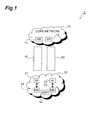
- Fig. 1 is a constitutional view of the mobile communication system of the first embodiment.
- Fig. 2 is a function block constitutional view of the MMF of the first embodiment.
- Fig. 3A is a pre-handover state diagram which serves to illustrate the logic of a seamless handover using multihoming, of a multihoming moving network.
- Fig. 3B is a state diagram of the state at the start of a handover which serves to illustrate the logic of a seamless handover using multihoming, of the multihoming moving network.
- Fig. 3C is a state diagram after handover completion which serves to illustrate the logic of a seamless handover using multihoming, of the multihoming moving network.
- Fig. 4A shows the state before the MMF issues a switching instruction in the mode in which the MH is not aware of switching.
- Fig. 4B shows the state after the MMF issues a switching instruction in the mode in which the MH is not aware of switching.
- Fig. 5 is a flowchart showing the MMF control operation of the example in Figs. 4A and 4B.
- Fig. 6A shows the state before the MMF issues a switching instruction in the mode in which the MH is aware of switching.
- Fig. 6B shows the state after the MMF issues a switching instruction in the mode in which the MH is aware of switching.
- Fig. 7 is a flowchart showing the MMF control operation of the example in Figs. 6A and 6B.
- Fig. 8 shows the initial state of the mobile communication system of the second embodiment.
- Fig. 9 is a function block constitutional view of the MMF of the second embodiment.
- Fig. 10 is a flowchart showing the velocity tracking processing on the basis of information based on a single AI combination.
- Fig. 11 shows the state immediately after the NAI is switched to the new AR.
- Fig. 12 shows the state immediately after the OAI is switched to the new AR.
- Fig. 13 is a diagram which serves to illustrate the processing in which a vector sum is calculated.
- Fig. 14 is a flowchart showing the velocity and the direction of movement tracking processing on the basis of information based on a plurality of AI combinations.
- Fig. 1 is a constitutional view of a mobile communication system of a first embodiment.
- a mobile communication system 1 is constituted by a core network 10, which is constituted comprising a plurality of access routers (referred to as "AR” hereinafter) 11, 12; and a moving network (referred to as “MN” hereinafter) 20, which is constituted comprising a plurality of access interfaces (referred to as “AI” hereinafter) 21, 22, a plurality of mobile hosts (referred to as “MH” hereinafter) 31, 32, and a control device (referred to as "MMF” hereinafter) 50 that is provided with a function for governing mobile management and switching instructions (MMF: Mobility Management Function).
- MMF moving network
- the MH 31 is connected to an AR (AR 11 in the example in Fig. 1) on the side of the core network 10 via either line 41 of the AI 21 or line 42 of the AI 22 (line 41 in the example in Fig. 1), and thus transmits and receives data.
- AR AR 11 in the example in Fig. 1
- the MN 20 moves from left to right in Fig. 1.
- the AI 22 which lies foremost in the direction of movement is called an NAI (New Access Interface)
- the AI 21 that lies rearward in the direction of movement is called an OAI (Old Access Interface).
- Fig. 2 is a function block constitutional view of the MMF 50 of the first embodiment.
- the MMF 50 is constituted comprising a connection status acquisition section 51, which acquires information from each AI on the connection status of each AI to the core network 10; a handover prediction section 52, which predicts a subsequent handover on the basis of the connection status information for each AI thus acquired; a change section 53 for dynamically changing the AI adopted as the connection interface in accordance with predetermined logic when a predetermined condition is satisfied on the basis of the connection status information for each AI or prediction information on a subsequent handover; and a downlink control unit 54 that performs control so that an MH is allowed to transmit downlink data from the core network 10 via an AR, of the AR 11, 12 on the side of the core network 10, which is connected to an AI (referred to as "FAI" (Fine AI) hereinafter) that is capable of maintaining a predetermined communication quality.
- FAI human AI
- Figs. 3A-3C show the logic for a handover using multihoming, of the MN 20 has the multihoming function.
- the two AI 21, 22 are connected to the same AR 11, and data packets are transmitted and received between the MN 20 and the core network 10 via the lines 41, 42 of the AI 21, 22 respectively.
- the NAI 22, which is frontward in the direction of movement transitionally enters a mode in which same is connected to the new AR 12, as shown in Fig 3B.
- the line 41 on the side of the OAI 21 is disconnected in keeping with movement.
- the MMF 50 implements close processing (that is, processing to disable the transmission and receipt of data although the line 41 is not disconnected) so that all the transmission data P1 and P2 is transmitted by using the line 42 to which the NAI 22 is connected. Further, after the handover has ended, the line 41 on the side of the OAI 21 can then be connected to the new AR 12 as shown in Fig. 3C, and hence a data transfer using two lines as per the initial state in Fig. 3A is feasible.
- Switching processing is thus switched locally without propagation to the entire network or informing the origin of the transmission as per an ordinary handover procedure. Hence, packet loss and a handover latency caused by a disconnection of the line on the side of the OAI and by performing non-local switching processing can be avoided, whereby a seamless handover can be implemented.
- Figs. 4A and 4B are state transition diagrams for the mode in which the MH is not aware of switching
- Fig. 5 is a flowchart showing the MMF control operation for the example of Figs. 4A and 4B.
- each AI 21, 22 reports the connection status to the core network 10, to the MMF 50 at fixed intervals.
- the MMF 50 receives information on the connection status between each AI and the core network 10 from each AI (S01), and, on the basis of this connection status information, judges whether the line quality of one AI is poor or not in light of a predetermined condition (S02).
- the predetermined condition may be that the field strength between the AI and core network 10 should be less than a predetermined threshold value, and may be that a predicted value for the field strength between the AI and the core network 10 that is predicted on the basis of subsequent movement prediction should be less than a predetermined threshold value.
- each of the AI 21, 22 is issued with an instruction for a mutual connection therebetween, and, more particularly, the OAI 21 receives an instruction to enter a closed state, and the core network 10 receives an instruction to transmit data via the AR 12 on the side of the FAI 22.
- the OAI 21, which has thus received the switching instruction causes the line 41 to enter a closed state so that data is not transmitted or received, without disconnecting the connection on the line 41 to the core network 10, and establishes a connection to the NAI 22. Further, also in the case of the core network 10, which has thus received a switching instruction, the AR 11 connected to the OAI 21 causes the line 41 to enter a closed state so that data is not transmitted or received, while still maintaining the connection on the line 41 to the OAI 21.
- a portion of the data transmitted from the MN 20 to the core network 10 can be transmitted to the core network 10 via the side of the NAI 22 access line 42 by passing via the connecting link between the OAI 21 and the NAI 22, without the MH 31, 32 in the MN 20 being aware of this operation. That is, as shown in Fig. 4B, the transmission data P1 transmitted by the MH 31 to the core network 10 is transmitted to the core network 10 via the side of the NAI 22 access line 42 together with the transmission data P2 transmitted by the MH 32 to the core network 10.
- Figs. 6A and 6B are the state transition diagrams of the mode in which the MH is aware of switching
- Fig. 7 is a flowchart showing the MMF control operation of the example in Figs. 6A and 6B.
- each AI 21, 22 reports the connection status to the core network 10, to the MMF 50 periodically.
- the MMF 50 receives information on the connection status between each AI and the core network 10 from each AI (S11), and, on the basis of this connection status information, it is judged whether the line quality of one AI is poor or not in light of predetermined conditions (S12) .
- the predetermined condition may be that the field strength between the AI and core network 10 should be less than a predetermined threshold value, and may be that a predicted value for the field strength between the AI and the core network 10 that is predicted on the basis of subsequent movement prediction should be less than a predetermined threshold value.
- processing returns to S11 and is repeated. If it is judged in S12 that the line quality of every AI is not poor, processing returns to S11 and is repeated. If it is judged in S12 that the line quality of one AI is poor, a switching instruction is transmitted to the OAI 21, the core network 10, and the MH 31 on the side of the OAI 21 (S13) . More specifically, the OAI 21 is issued with an instruction to enter a closed state, the core network 10 receives an instruction to transmit data via the AR 12 on the side of the FAI 22, and the MH 31 receives an instruction to connect to the NAI 22 instead of the OAI 21.
- the OAI 21 which has thus received the switching instruction, causes the line 41 to enter a closed state so that data is not transmitted or received, without disconnecting the connection on the line 41 to the core network 10. Further, also in the case of the core network 10, which has thus received a switching instruction, the AR 11 connected to the OAI 21 causes the line 41 to enter a closed state so that data is not transmitted or received, while still maintaining the connection on the line 41 to the OAI 21.
- the MH 31 establishes a connection to the NAI 22 instead of the OAI 21.
- the transmission data P1 transmitted by the MH 31 to the core network 10 can be transmitted to the core network 10 via the side of the NAI 22 access line 42 by way of the connecting link between the MH 31 and the NAI 22, as per Fig. 6B.
- switching is performed locally without propagation to the entire network or informing the origin of the transmission, as is the case for an ordinary handover procedure.
- packet loss and a handover latency caused by a disconnection of the line on the side of the OAI and by performing non-local switching processing can be avoided, whereby a seamless handover can be implemented.
- an AI corresponding with the maximum-value field strength may be selected from among the field strengths between each AI and the core network 10, for example.
- an AI that corresponds with the predicted value for the maximum-value field strength may be selected from among predicted values for the field strengths between each AI and the core network 10 which are predicted on the basis of subsequent movement prediction.
- Fig. 8 is a constitutional view of the initial state of a mobile communication system 1S of the second embodiment.
- a mobile communication system 1S is constituted by the core network 10, which is constituted comprising a plurality of AR 11, 12; and the MN 20, which is constituted comprising a plurality of AI 21, 22, the MH 31, and a control device (MMF) 50 that is provided with a function for governing mobile management and switching instructions (MMF: Mobility Management Function).
- MMF Mobility Management Function
- the MN 20 moves from left to right in Fig. 8.
- the AI 22 that lies foremost in the direction of movement is called an NAI (New Access Interface)
- the AI 21 that lies rearward in the direction of movement is called an OAI (Old Access Interface).
- the MN 20 is therefore a moving network in which the two AI 21, 22 are multihomed.
- Fig. 9 is a function block constitutional view of the MMF 50 of the second embodiment.
- the connection status acquisition section 51 is constituted comprising a locational relationship tracking section 51A that tracks the locational relationship of all the AI, an information receiver section 51B that receives information on the connection status of each AI to the core network 10, and switching information that includes identification information for identifying the switching origin AR when switching occurs and the switching destination AR, as well as switching end time information, the information being reported by each AI.
- the handover prediction section 52 is constituted comprising a velocity tracking section 52A for tracking at least velocity information pertaining to the MN 20 in accordance with a tracking logic (described later), on the basis of the locational relationship of each AI thus tracked and the connection status information and switching information thus received, and a prediction section 52B for predicting subsequent movement and changes in the field strength from the tracked information.
- the velocity tracking section 52A pre-stores information on the distance x between the two AI 21, 22, and, upon recognizing, on the basis of the switching information from each AI, that adjacent switching is with respect to the same AR, the velocity tracking section 52A tracks, given a switching time difference t for the adjacent switching and a distance x between the two AI, a value obtained by dividing the distance x by the switching time difference t as the velocity pertaining to the MN 20.
- Velocity tracking processing which is based on switching information from a single AI combination (that is, the two AI 21, 22) executed by the MMF 50, will be described hereinbelow on the basis of the flowchart of Fig. 10 and the state diagrams of Figs. 8, 11, and 12.
- the mobile communication system is in the initial state of Fig. 8, and the AI 21, 22 report the connection status to the core network 10, to the MMF 50 periodically.
- the MMF 50 receives information on the connection status between each AI and the core network 10 from each AI (S21), and, on the basis of this connection status information, judges whether the line quality of one AI is poor or not in light of predetermined conditions (S22).
- the predetermined conditions may be that the field strength between the AI and core network 10 should be less than a predetermined threshold value, and may be that a predicted value for the field strength between the AI and the core network 10 predicted on the basis of subsequent movement prediction, should be less than a predetermined threshold value.
- the NAI 22 and core network 10 which have thus received the switching instruction, switch the connection destination of the NAI 22 to the new AR 12, and hence the AR 12 and NAI 22 are connected by the line 42. Further, location information on the new AR 12 and information about the time (switching time) t1 when switching to the AR 12 has completed, are transmitted to the MMF 50.
- the MMF 50 receives the location information on the new AR 12 and the information about the switching time t1 from the NAI 22, and cumulatively stores them (S24) . Because, at this time, only one AI 22 is switched, S25 yields a negative judgment, and processing returns to S21, whereupon the processing of step S21 and subsequent steps are executed once again.
- the MMF 50 transmits a switching instruction for the OAI 21 and the core network 10 to switch the connection destination of the OAI 21 from the current AR 11 to the new AR.
- the OAI 21 and core network 10 which have thus received the switching instruction, switch the connection destination of the OAI 21 to the new AR 12, and hence the AR 12 and OAI 21 are connected by the line 41. Further, location information on the new AR 12 and information about the time (switching time) t2 when switching to the AR 12 has completed, is transmitted to the MMF 50.
- the MMF 50 receives the location information on the new AR 12 and the information about the switching time t2 from the OAI 21, and cumulatively stores them (S24). Because, at this time, the location information on the new AR and the information about the switching time have been received from both of the two AI, S25 yields an affirmative judgment, and processing proceeds to S26.
- the velocity tracking section 52A recognizes that the switching between the two AI 22, 21 is the switching between the same AR, by the fact that the location information on the new AR 12 of the NAI 22 corresponds to the location information on the new AR 12 of the OAI 21.
- the velocity tracking section 52A obtains a value by dividing the pre-prepared distance x between the AI 21, 22 by the switching time difference t (where t is equivalent to (t2-t1)) for the two switching events, and tracks the value as the velocity pertaining to the MN 20. Further, at such time, the velocity tracking section 52A is able to track the direction of movement in which the NAI 22 locates forward side and the OAI 21 locates backward side, as the direction of movement of the MN 20.
- the prediction section 52B is able to predict the subsequent movement of the MN 20 and change in the field strength on the basis of the velocity and the direction of movement of the MN 20.
- MN velocity tracking was described in the above description on the basis of the switching information from one combination of AIs (that is, the two AI 21, 22), the velocity and the direction of movement of the MN can be tracked as detailed below, on the basis of switching information from plural combinations of AIs (that is, three or more AI), by applying the above-described technology to practical use.
- the processing of Fig. 14 is executed by the MMF 50.
- the velocity tracking section 52A executes the above-described velocity tracking processing in Fig. 10, for each of a plurality of combinations of the AIs.
- two velocity vectors v1, v2 are obtained as shown in Fig. 13 on the basis of the switching information from two combinations of AIs.
- the direction of each velocity vector is equivalent to the tracked direction of movement
- the size of each velocity vector is equivalent to a value for the tracked velocity.
- the velocity tracking section 52A calculates a vector sum in S33, and, in S34, tracks the direction of movement and the velocity of the MN on the basis of the vector obtained.
- a synthesized vector V is obtained by calculating the vector sum of the two velocity vectors v1, v2, and the direction of movement of the MN can be tracked on the basis of the direction of the synthesized vector V, and the velocity of the MN can be tracked on the basis of the size of this synthesized vector V.
- the prediction section 52B is able to predict the subsequent movement and change in the field strength of the MN 20 on the basis of the velocity and direction of movement of the tracked MN 20.
- the velocity and direction of movement of the MN 20 can also be tracked on the basis of either the switching information from one combination of AIs (two AIs) or switching information from a plurality of combinations of AIs (three or more AIs), and the subsequent movement and change in the field strength is predicted on the basis of the tracked information. For this reason, handover prediction information of favorable accuracy can be obtained, and it is possible to implement a seamless handover more reliably.
- the access interface adopted as the connection interface is dynamically changed on the basis of this connection status information or subsequent handover prediction information.
Landscapes
- Engineering & Computer Science (AREA)
- Computer Networks & Wireless Communication (AREA)
- Signal Processing (AREA)
- Mobile Radio Communication Systems (AREA)
- Data Exchanges In Wide-Area Networks (AREA)
- Small-Scale Networks (AREA)
Applications Claiming Priority (2)
| Application Number | Priority Date | Filing Date | Title |
|---|---|---|---|
| JP2002313092A JP2004153316A (ja) | 2002-10-28 | 2002-10-28 | ハンドオーバ制御方法、移動通信システム及び制御装置 |
| EP20030024375 EP1416755A3 (de) | 2002-10-28 | 2003-10-24 | Steuervorrichtung, Handoversteuerungsverfahren und Mobilkommunikationssystem |
Related Parent Applications (1)
| Application Number | Title | Priority Date | Filing Date |
|---|---|---|---|
| EP20030024375 Division EP1416755A3 (de) | 2002-10-28 | 2003-10-24 | Steuervorrichtung, Handoversteuerungsverfahren und Mobilkommunikationssystem |
Publications (2)
| Publication Number | Publication Date |
|---|---|
| EP1804548A2 true EP1804548A2 (de) | 2007-07-04 |
| EP1804548A3 EP1804548A3 (de) | 2007-08-22 |
Family
ID=32089476
Family Applications (2)
| Application Number | Title | Priority Date | Filing Date |
|---|---|---|---|
| EP20070008015 Withdrawn EP1804548A3 (de) | 2002-10-28 | 2003-10-24 | Steuervorrichtung, Steuerverfahren für die Weiterreichung und mobiles Kommunikationssystem |
| EP20030024375 Withdrawn EP1416755A3 (de) | 2002-10-28 | 2003-10-24 | Steuervorrichtung, Handoversteuerungsverfahren und Mobilkommunikationssystem |
Family Applications After (1)
| Application Number | Title | Priority Date | Filing Date |
|---|---|---|---|
| EP20030024375 Withdrawn EP1416755A3 (de) | 2002-10-28 | 2003-10-24 | Steuervorrichtung, Handoversteuerungsverfahren und Mobilkommunikationssystem |
Country Status (4)
| Country | Link |
|---|---|
| US (2) | US20040082329A1 (de) |
| EP (2) | EP1804548A3 (de) |
| JP (1) | JP2004153316A (de) |
| CN (2) | CN1312888C (de) |
Families Citing this family (18)
| Publication number | Priority date | Publication date | Assignee | Title |
|---|---|---|---|---|
| JP4385223B2 (ja) * | 2004-06-30 | 2009-12-16 | 日本電気株式会社 | 移動体通信システム、基地局制御装置及びそれらに用いる送信電力制御方法並びにそのプログラム |
| WO2006093288A1 (ja) * | 2005-03-04 | 2006-09-08 | Matsushita Electric Industrial Co., Ltd. | 通信ノード及び通信制御方法 |
| CN100461959C (zh) * | 2006-03-24 | 2009-02-11 | 华为技术有限公司 | 一种高速移动终端的小区切换控制方法 |
| WO2009010814A1 (en) * | 2007-07-13 | 2009-01-22 | Telefonaktiebolaget Lm Ericsson (Publ) | A system and method of providing denial of service protection in a telecommunication system |
| US20100054210A1 (en) * | 2008-09-02 | 2010-03-04 | Sony Ericsson Mobile Communications Ab | Wireless network transitioning for mobile devices |
| EP2282592B1 (de) * | 2009-07-03 | 2016-08-24 | Alcatel Lucent | Verstärkung des netzbasierten IP-Mobilitätsverwaltungsprotokolls zur Bereitstellung von Multihoming-Unterstützung |
| US9787501B2 (en) | 2009-12-23 | 2017-10-10 | Pismo Labs Technology Limited | Methods and systems for transmitting packets through aggregated end-to-end connection |
| WO2014031597A1 (en) | 2012-08-24 | 2014-02-27 | Oceus Networks Inc. | Mobile cellular networks |
| WO2014031689A1 (en) | 2012-08-24 | 2014-02-27 | Oceus Networks Inc. | Mobile cellular networks |
| WO2014179235A1 (en) | 2013-04-29 | 2014-11-06 | Oceus Networks Inc. | Mobile cellular network backhaul |
| WO2015001393A1 (en) * | 2013-07-05 | 2015-01-08 | Pismo Labs Technology Ltd. | Methods and systems for transmitting packets through aggregated end-to-end connection |
| US20160088143A1 (en) * | 2014-09-24 | 2016-03-24 | Intel Corporation | Method, system and apparatus for graceful disconnection from a wireless docking station |
| US9571624B2 (en) | 2015-03-24 | 2017-02-14 | Intel IP Corporation | Apparatus, system and method of terminating a docking session between a mobile device and a docking device |
| US10873891B2 (en) | 2016-07-06 | 2020-12-22 | Oceus Networks, Llc | Secure network rollover |
| US9924427B2 (en) | 2016-07-07 | 2018-03-20 | Oceus Networks Inc. | Network backhaul access |
| US9686238B1 (en) | 2016-07-07 | 2017-06-20 | Oceus Networks Inc. | Secure network enrollment |
| US10172078B2 (en) | 2017-03-31 | 2019-01-01 | Oceus Networks Inc. | Targeted user equipment-base station communication link |
| US11246031B2 (en) | 2018-08-15 | 2022-02-08 | Oceus Networks, Llc | Disguising UE communications in a cellular network |
Family Cites Families (15)
| Publication number | Priority date | Publication date | Assignee | Title |
|---|---|---|---|---|
| GB2273424A (en) * | 1992-12-14 | 1994-06-15 | Motorola Ltd | A cellular communications system and method for hand-off |
| US5612948A (en) * | 1994-11-18 | 1997-03-18 | Motorola, Inc. | High bandwidth communication network and method |
| US5657325A (en) * | 1995-03-31 | 1997-08-12 | Lucent Technologies Inc. | Transmitter and method for transmitting information packets with incremental redundancy |
| US6385464B1 (en) * | 1996-11-26 | 2002-05-07 | Sanyo Electric Co., Ltd. | Base station for mobile communication system |
| JPH10164640A (ja) | 1996-11-28 | 1998-06-19 | Matsushita Electric Works Ltd | 移動体通信システム |
| JPH11355831A (ja) * | 1998-04-10 | 1999-12-24 | Nec Corp | Cdmaセルラシステムにおける異通信方式セルラシステム基地局へのハンドオフ方法およびセルラシステム |
| US6381458B1 (en) * | 1998-05-15 | 2002-04-30 | Telefonaktiebolaget Lm Ericsson (Publ) | Method and system for soft handoff control based on access network capacity |
| GB2341047B (en) * | 1998-08-19 | 2003-09-10 | Motorola Ltd | Method and apparatus for streamlining in a communication system |
| US6320843B1 (en) * | 1998-11-18 | 2001-11-20 | Ericsson Inc. | Wireless communications systems with standard and robust services and methods of operation thereof |
| US6965948B1 (en) * | 1999-11-12 | 2005-11-15 | Telefonaktiebolaget Lm Ericsson (Publ) | Method and apparatus for selective network access |
| FI109862B (fi) * | 2000-01-10 | 2002-10-15 | Nokia Corp | Menetelmä taajuudenvälisen yhteydenvaihdon valmistelemiseksi, verkkoelementti ja matkaviestin |
| SE516727C2 (sv) * | 2000-04-11 | 2002-02-19 | Ericsson Telefon Ab L M | Förfarande och anordning för att minska mängden handover- relaterad signaltrafik i ett telekommunikationssystem |
| US6985731B1 (en) * | 2001-04-02 | 2006-01-10 | Bellsouth Intellectual Property Corporation | Location defined control of cellular system |
| US7013149B2 (en) * | 2002-04-11 | 2006-03-14 | Mitsubishi Electric Research Laboratories, Inc. | Environment aware services for mobile devices |
| US7453858B2 (en) * | 2002-04-26 | 2008-11-18 | Samsung Electronics Co., Ltd. | Apparatus and method for adapting WI-FI access point to wireless backhaul link of a wireless network |
-
2002
- 2002-10-28 JP JP2002313092A patent/JP2004153316A/ja active Pending
-
2003
- 2003-10-23 US US10/690,524 patent/US20040082329A1/en not_active Abandoned
- 2003-10-24 EP EP20070008015 patent/EP1804548A3/de not_active Withdrawn
- 2003-10-24 EP EP20030024375 patent/EP1416755A3/de not_active Withdrawn
- 2003-10-28 CN CNB2003101043909A patent/CN1312888C/zh not_active Expired - Fee Related
- 2003-10-28 CN CNA2007100881682A patent/CN101035377A/zh not_active Withdrawn
-
2007
- 2007-09-20 US US11/858,677 patent/US7684801B2/en not_active Expired - Fee Related
Also Published As
| Publication number | Publication date |
|---|---|
| CN101035377A (zh) | 2007-09-12 |
| EP1416755A2 (de) | 2004-05-06 |
| EP1416755A3 (de) | 2006-05-17 |
| CN1312888C (zh) | 2007-04-25 |
| US20080051089A1 (en) | 2008-02-28 |
| US7684801B2 (en) | 2010-03-23 |
| JP2004153316A (ja) | 2004-05-27 |
| US20040082329A1 (en) | 2004-04-29 |
| EP1804548A3 (de) | 2007-08-22 |
| CN1499795A (zh) | 2004-05-26 |
Similar Documents
| Publication | Publication Date | Title |
|---|---|---|
| US7684801B2 (en) | Control device, handover control method and mobile communication system | |
| EP2156573B1 (de) | Multimodus-endgerät zur unterstützung eines schnellen handover zwischen heterogenen netzen | |
| EP1643693B1 (de) | Mobilkommunikationsverfahren, mobilkommunikationsvorrichtung, heimagentvorrichtung, zugangsrouterinformationsservervorrichtung und mobilkommunikationssystem | |
| US20070171875A1 (en) | Mobile communication system and mobile communication method | |
| US7924790B2 (en) | Radio base station apparatus and base station controller | |
| EP1675322B1 (de) | Kontrollvorrichtung, mobiles Endgerät und Kommunikationskontrollverfahren | |
| US7554950B2 (en) | Handover method and mobile communication system and mobile terminal using same | |
| JP2005027314A (ja) | モバイルIPv6ホームエージェントのシームレスハンドオーバー方法 | |
| JP2009253678A (ja) | 移動無線通信システムおよびアクセスゲートウェイ | |
| KR20060023564A (ko) | 이동 단말장치 및 그 통화채널전환 방법 | |
| EP1983795B1 (de) | Verfahren zur Durchführung einer vertikalen Weiterreichung zwischen verschiedenen drahtlosen Netzwerken | |
| US20040166898A1 (en) | Radio base station apparatus and inter-network interfacing apparatus | |
| EP1353479B1 (de) | Paketkommunikationssystem | |
| US8189510B2 (en) | Mobile IP communication system | |
| KR20060128638A (ko) | IPv6 기반 모바일 시스템에서 빠른 리액티브핸드오버를 수행하는 장치 | |
| EP1494405B1 (de) | Mobiler Knoten, mobiles Kommunikationssystem, Verfahren zur Kommunikationssteuerung und Zugangsrouter | |
| CN101951647B (zh) | 前向链路和反向链路服务接入点的改变 | |
| EP1558047A1 (de) | Diversity-weiterreichungsverfahren in der mobilkommunikation, steuerstation und mobilendgerät | |
| JP4685052B2 (ja) | ハンドオーバ制御方法、移動通信システム及び制御装置 | |
| EP1603352A1 (de) | Vorrichtung mit zweitem Funkverbindungsteil zum Ermöglichen eines Handover eines mobilen Endgeräts mit erstem Funkverbindungsteil | |
| KR100639419B1 (ko) | 이동 아이피 망에서 신뢰성 있는 멀티캐스트 서비스를지원하는 빠른 핸드오버 방법 | |
| US20240388986A1 (en) | Communication system, communication method, communication device, communication program | |
| US20020126665A1 (en) | Wireless lan system and method for the same | |
| CN101540729A (zh) | 数据传输方法和装置 | |
| Huang et al. | Distributed mobility management (DMM) using the software defined network (SDN)-based backward fast handover (SBF-DMM) method |
Legal Events
| Date | Code | Title | Description |
|---|---|---|---|
| PUAI | Public reference made under article 153(3) epc to a published international application that has entered the european phase |
Free format text: ORIGINAL CODE: 0009012 |
|
| AC | Divisional application: reference to earlier application |
Ref document number: 1416755 Country of ref document: EP Kind code of ref document: P |
|
| AK | Designated contracting states |
Kind code of ref document: A2 Designated state(s): AT BE BG CH CY CZ DE DK EE ES FI FR GB GR HU IE IT LI LU MC NL PT RO SE SI SK TR |
|
| AX | Request for extension of the european patent |
Extension state: AL LT LV MK |
|
| RIC1 | Information provided on ipc code assigned before grant |
Ipc: H04L 12/56 20060101ALI20070614BHEP Ipc: H04Q 7/38 20060101AFI20070614BHEP |
|
| PUAL | Search report despatched |
Free format text: ORIGINAL CODE: 0009013 |
|
| AK | Designated contracting states |
Kind code of ref document: A3 Designated state(s): AT BE BG CH CY CZ DE DK EE ES FI FR GB GR HU IE IT LI LU MC NL PT RO SE SI SK TR |
|
| AX | Request for extension of the european patent |
Extension state: AL LT LV MK |
|
| 17P | Request for examination filed |
Effective date: 20080218 |
|
| AKX | Designation fees paid |
Designated state(s): DE GB |
|
| 17Q | First examination report despatched |
Effective date: 20080701 |
|
| STAA | Information on the status of an ep patent application or granted ep patent |
Free format text: STATUS: THE APPLICATION IS DEEMED TO BE WITHDRAWN |
|
| 18D | Application deemed to be withdrawn |
Effective date: 20150527 |