EP1803531A1 - Pressure-sensitive adhesive tape for fixing lens and method for processing lens using the same - Google Patents
Pressure-sensitive adhesive tape for fixing lens and method for processing lens using the same Download PDFInfo
- Publication number
- EP1803531A1 EP1803531A1 EP05790630A EP05790630A EP1803531A1 EP 1803531 A1 EP1803531 A1 EP 1803531A1 EP 05790630 A EP05790630 A EP 05790630A EP 05790630 A EP05790630 A EP 05790630A EP 1803531 A1 EP1803531 A1 EP 1803531A1
- Authority
- EP
- European Patent Office
- Prior art keywords
- lens
- adhesive tape
- adhesive
- plastic foam
- fixing
- Prior art date
- Legal status (The legal status is an assumption and is not a legal conclusion. Google has not performed a legal analysis and makes no representation as to the accuracy of the status listed.)
- Granted
Links
Images

Classifications
-
- B—PERFORMING OPERATIONS; TRANSPORTING
- B24—GRINDING; POLISHING
- B24B—MACHINES, DEVICES, OR PROCESSES FOR GRINDING OR POLISHING; DRESSING OR CONDITIONING OF ABRADING SURFACES; FEEDING OF GRINDING, POLISHING, OR LAPPING AGENTS
- B24B13/00—Machines or devices designed for grinding or polishing optical surfaces on lenses or surfaces of similar shape on other work; Accessories therefor
- B24B13/005—Blocking means, chucks or the like; Alignment devices
-
- C—CHEMISTRY; METALLURGY
- C09—DYES; PAINTS; POLISHES; NATURAL RESINS; ADHESIVES; COMPOSITIONS NOT OTHERWISE PROVIDED FOR; APPLICATIONS OF MATERIALS NOT OTHERWISE PROVIDED FOR
- C09J—ADHESIVES; NON-MECHANICAL ASPECTS OF ADHESIVE PROCESSES IN GENERAL; ADHESIVE PROCESSES NOT PROVIDED FOR ELSEWHERE; USE OF MATERIALS AS ADHESIVES
- C09J7/00—Adhesives in the form of films or foils
- C09J7/20—Adhesives in the form of films or foils characterised by their carriers
- C09J7/22—Plastics; Metallised plastics
-
- B—PERFORMING OPERATIONS; TRANSPORTING
- B29—WORKING OF PLASTICS; WORKING OF SUBSTANCES IN A PLASTIC STATE IN GENERAL
- B29D—PRODUCING PARTICULAR ARTICLES FROM PLASTICS OR FROM SUBSTANCES IN A PLASTIC STATE
- B29D11/00—Producing optical elements, e.g. lenses or prisms
- B29D11/00009—Production of simple or compound lenses
- B29D11/00038—Production of contact lenses
-
- C—CHEMISTRY; METALLURGY
- C09—DYES; PAINTS; POLISHES; NATURAL RESINS; ADHESIVES; COMPOSITIONS NOT OTHERWISE PROVIDED FOR; APPLICATIONS OF MATERIALS NOT OTHERWISE PROVIDED FOR
- C09J—ADHESIVES; NON-MECHANICAL ASPECTS OF ADHESIVE PROCESSES IN GENERAL; ADHESIVE PROCESSES NOT PROVIDED FOR ELSEWHERE; USE OF MATERIALS AS ADHESIVES
- C09J7/00—Adhesives in the form of films or foils
- C09J7/20—Adhesives in the form of films or foils characterised by their carriers
- C09J7/22—Plastics; Metallised plastics
- C09J7/26—Porous or cellular plastics
-
- C—CHEMISTRY; METALLURGY
- C09—DYES; PAINTS; POLISHES; NATURAL RESINS; ADHESIVES; COMPOSITIONS NOT OTHERWISE PROVIDED FOR; APPLICATIONS OF MATERIALS NOT OTHERWISE PROVIDED FOR
- C09J—ADHESIVES; NON-MECHANICAL ASPECTS OF ADHESIVE PROCESSES IN GENERAL; ADHESIVE PROCESSES NOT PROVIDED FOR ELSEWHERE; USE OF MATERIALS AS ADHESIVES
- C09J7/00—Adhesives in the form of films or foils
- C09J7/30—Adhesives in the form of films or foils characterised by the adhesive composition
- C09J7/38—Pressure-sensitive adhesives [PSA]
-
- C—CHEMISTRY; METALLURGY
- C09—DYES; PAINTS; POLISHES; NATURAL RESINS; ADHESIVES; COMPOSITIONS NOT OTHERWISE PROVIDED FOR; APPLICATIONS OF MATERIALS NOT OTHERWISE PROVIDED FOR
- C09J—ADHESIVES; NON-MECHANICAL ASPECTS OF ADHESIVE PROCESSES IN GENERAL; ADHESIVE PROCESSES NOT PROVIDED FOR ELSEWHERE; USE OF MATERIALS AS ADHESIVES
- C09J2301/00—Additional features of adhesives in the form of films or foils
- C09J2301/10—Additional features of adhesives in the form of films or foils characterized by the structural features of the adhesive tape or sheet
- C09J2301/12—Additional features of adhesives in the form of films or foils characterized by the structural features of the adhesive tape or sheet by the arrangement of layers
- C09J2301/124—Additional features of adhesives in the form of films or foils characterized by the structural features of the adhesive tape or sheet by the arrangement of layers the adhesive layer being present on both sides of the carrier, e.g. double-sided adhesive tape
-
- C—CHEMISTRY; METALLURGY
- C09—DYES; PAINTS; POLISHES; NATURAL RESINS; ADHESIVES; COMPOSITIONS NOT OTHERWISE PROVIDED FOR; APPLICATIONS OF MATERIALS NOT OTHERWISE PROVIDED FOR
- C09J—ADHESIVES; NON-MECHANICAL ASPECTS OF ADHESIVE PROCESSES IN GENERAL; ADHESIVE PROCESSES NOT PROVIDED FOR ELSEWHERE; USE OF MATERIALS AS ADHESIVES
- C09J2400/00—Presence of inorganic and organic materials
- C09J2400/20—Presence of organic materials
- C09J2400/26—Presence of textile or fabric
- C09J2400/263—Presence of textile or fabric in the substrate
-
- Y—GENERAL TAGGING OF NEW TECHNOLOGICAL DEVELOPMENTS; GENERAL TAGGING OF CROSS-SECTIONAL TECHNOLOGIES SPANNING OVER SEVERAL SECTIONS OF THE IPC; TECHNICAL SUBJECTS COVERED BY FORMER USPC CROSS-REFERENCE ART COLLECTIONS [XRACs] AND DIGESTS
- Y10—TECHNICAL SUBJECTS COVERED BY FORMER USPC
- Y10T—TECHNICAL SUBJECTS COVERED BY FORMER US CLASSIFICATION
- Y10T428/00—Stock material or miscellaneous articles
- Y10T428/14—Layer or component removable to expose adhesive
- Y10T428/1476—Release layer
Abstract
Description
- The present invention relates to an adhesive tape for fixing a lens used to protect a surface of the lens and to fix a holding jig during chamfering, grooving, or the like of the lens and further relates to a lens processing method using this tape.
- For example, in the lens of glasses and the like, lens processing is necessary to adjust the shape of the lens to fit the shape of the frame, design of the frame, and the like, and therefore machining (known as edging) such as grooving or chamfering with a grindstone is executed. To execute the machining described above for the lens, a so-called lens-grinding machine is used and the shape of the lens can be altered to fit the shape of the frame of the glasses by mounting the lens supplied by the lens maker in the grinding machine and grinding the periphery with a grindstone.
- The lens grinding machine, for example, is structured in a manner such that it contains a grinding chamber to process the lens, sandwiches the lens between a pair of clamp arms extending from drive units disposed on both sides of the grinding chamber, and grinds the periphery of the lens with the grindstone as the clamp arms rotate. A holding jig is attached to the tip of one of the clamp arms, the tip of the other clamp arm is equipped with an elastic material such as rubber and becomes the lens holder, and the lens to be processed is fixed by being sandwiched between these two clamp arms.
- At this time, when the holding jig directly contacts the surface of the lens to be processed, since there are the worries that, for example, the surface of the lens to be processed will be scratched and that accurate processing cannot be performed because of possibilities such as the holding jig slipping and causing axial misalignment, adhesive tape is interposed between the holding jig and the lens to be processed when the lens to be processed is sandwiched by the holding jig.
- In recent years, various surface coatings are administered to the lens used for glasses and the like, creating the problem that common adhesive tape cannot achieve sufficient adhesion. For example, in a lens with antifouling coating that makes dirt less likely to stick to the surface, the antifouling layer (water repellent coating) is formed by coating the surface of the lens with water repellent material such as a fluorine-containing silane compound. This water repellent coating does not only make dirt less likely to stick, but also has low hydrophilic properties in relation to the adhesive agent of the adhesive tape, and notably decreases the friction coefficient. Accordingly, with common adhesive tape, there is the problem that a large amount of holding power cannot be achieved and precise processing is impossible because of axial misalignment.
- Considering the condition described above, various improvements have been attempted for the fixing of the lens with adhesive tape (see, e.g., Patent Document 1 (
Japanese Patent Application Publication No. 2004-122302 Japanese Patent Application Publication No. 2004-249454 Patent Document 1, a transparent adhesive sheet, that contains a surface having hydrophilic properties more favorable than the surface of the lens in relation to the adhesive agent and provided with an adhesive layer on the side of the lens, is affixed to the lens surface to attach the holding jig on the adhesive sheet via a double sided adhesive tape. - On the other hand, the invention described in patent document 2, for example, proposes a method for distinguishing adhesive tape having superior adhesive strength in relation to the antifouling layer formed mainly of a fluorine-containing silane compound, and adhesive strength in relation to the antifouling layer is assured to prevent axial misalignment by selecting the adhesive strength greater than or equal to a prescribed value in a case where a polyethylene terephthalate plate serving as a test plate that receives surface processing with a fluorinated silicone release agent I used.
- However, as shown in the invention of
Patent Document 1, in the method that simultaneously uses the adhesive sheet and the double sided adhesive tape, not only is the process of affixing the sheet and tape troublesome, but also there are unsatisfactory costs because an adhesive sheet with a large surface area is necessary. Furthermore, because of the water repellent coating, it is difficult to completely eliminate axial misalignment because sufficient holding power cannot be reliably achieved even with the large surface area of the adhesive sheet. - On the other hand, as shown in the invention of Patent Document 2, in a case where focus is placed on the adhesive strength of the adhesive tape, the use of the adhesive tape having high adhesive strength in relation to the antifouling layer leads to the prevention of axial misalignment, but where merely using the adhesive tape having high adhesive strength, the amount of strength required to peel off the adhesive tape is too great, creating the possibility that the antifouling layer or the like is also removed at a time when the adhesive tape is removed after processing. Therefore formation of a supplemental piece for protecting the surface coating becomes necessary, leading to a higher cost of the adhesive tape.
- The present invention is proposed with consideration given to the conventional situation. That is, the present invention is intended to provide the adhesive tape for fixing a lens that can exhibit sufficient adhesive strength in relation to the lens that received surface processing and can fix the lens with sufficient strength without the use of an extra adhesive sheet or the like. Furthermore, the present invention is intended to provide the adhesive tape for fixing the lens that, while having sufficient adhesive strength in relation to the lens, has an appropriate level of strength when peeled off, and can achieve both a strong holding force and easy removal. Yet further, the present invention is intended to provide a lens processing method by which, through use of the aforementioned types of adhesive tape for fixing the lens, precise processing can be executed without axial misalignment or the like and the lens to be processed can be easily attached and removed with the use of the aforementioned types of adhesive tape for fixing the lens
- To achieve the aforementioned goals, according to this invention, an adhesive tape for fixing a lens, which is interposed between a lens to be processed and a holding jig in the case where the lens to be processed is mounted in a lens processing machine, has a plastic foam material containing openings in an adhering surface, and an adhesive layer formed on the adhering surface of the plastic foam material, the adhesive tape for fixing a lens having a suction function for providing suction to the adhering surface in accordance with elastic restoration after the plastic foam material is deformed under compression.
- Furthermore, according to this invention, a lens processing method has the steps of interposing an adhesive tape for fixing a lens between a lens to be processed and a holding jig, and fixing the lens to be processed by the holding jig via the adhesive tape for fixing a lens. The interposing process and the fixing process are executed in machining process. The machining process uses the adhesive tape for fixing a lens including a plastic foam material containing openings in a surface to be adhered and an adhesive layer formed on the surface to be adhered of the plastic foam. The adhesive tape for fixing a lens has a suction function for providing suction to the surface to be adhered along with elastic restoration after the plastic foam material is deformed under compression.
- During the lens processing, in a case where the lens to be processed is fixed by the holding jig and processed with the grindstone while the lens is being rotated, a large amount of shear force is added to the adhesive tape interposed between the lens to be processed and the holding jig. Accordingly, it is desirable that the adhesive tape have a high shear adhesive strength.
- The adhesive tape contains the plastic foam material containing openings in a adhering surface, the adhesive layer formed on the adhering surface of the plastic foam material, and also has the suction function for providing suction to the adhering surface in accordance with elastic restoration after the plastic foam material is deformed under compression. The adhesive tape has significantly stronger adhesive strength in comparison to the conventional adhesive tape, and is formed such that the strongly adhesive structure is formed so the adhesive tape stably attaches to the lens surface through the suction function. Furthermore, the shear adhesive also has a sufficient effect on the lens surface that has been treated with water repellant coating or the like. Accordingly, this type of adhesive tape is optimal for fixing the lens to be processed that has received surface processing. Actually, where the adhesive tape having the suction function was used to fix the lens to be processed treated with the water repellant coating, it has been confirmed that a stable and fixed condition can be realized without axial misalignment or the like because of the high shear adhesive strength.
- In addition, in a case of fixing the lens to be processed having a covering on the surface such as the water repellant coating, excessively high adhesive strength for removing the tape (peeling strength) can cause damage to the surface coating. The adhesive tape having the suction function used in the present invention has very high shear adhesive strength, but has a low adhesive strength for removing the tape, in other words, the adhesive tape of the present invention has a highly removable property. Accordingly, at the time of removal, the adhesive tape can quickly be removed from the surface of the lens after processing without damaging the surface coating. Furthermore, the supplemental piece for protecting the surface coating when the adhesive tape is removed is unnecessary.
- The adhesive tape for fixing the lens of the present invention can exhibit sufficient shear adhesive strength in relation to the lens that received surface processing and can fix the lens to be processed with sufficient strength without the use of an extra adhesive sheet. Furthermore, despite having the high shear adhesive strength, the adhesive tape for fixing the lens of the present invention is easily removable after use without damaging the coating layer or the like on the surface of the lens because the adhesive tape has an appropriate adhesive strength for removal.
- On the other hand, according to the present invention, the lens to be processed can easily be attached or removed and the machining process, such as chamfering or grooving by the grindstone, can be executed without causing axial misalignment.
-
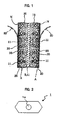
- Fig. 1 is a cross sectional view of essential parts showing a structure of a adhesive tape for fixing a lens;
- Fig. 2 is a planar view showing a planar state of the adhesive tape for fixing the lens;
- Fig. 3 is an exploded perspective view showing a structure of a fixed lens to be processed;
- Fig. 4 is a cross sectional view showing a state of the fixed lens to be processed; and
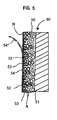
- Fig. 5 is a cross sectional view of essential parts showing another structure of the adhesive tape for fixing the lens.
- The following is a detailed description, given with diagrams, of an adhesive tape for fixing a lens and a lens processing method as applicable to the present invention.
- First, the basic structure of the adhesive tape for fixing the lens of the present invention will be described. The adhesive tape for fixing the lens of the present invention is formed of a so-called strongly adhesive structure, in which a plastic foam material having an adhesive layer is equipped with porous openings on a surface (attachment surface) to be affixed to an adhesion target of the plastic foam material. Along with elastic restoration after the plastic foam material is deformed under compression, the plastic foam material has a suction function that responds with negative pressure to attach to the adhesion target surface.
- In the strongly adhesive structure formed as described above, the adhesion function and the suction function act simultaneously on the attachment target surface and can reliably mutually fasten the attachment targets to each other. That is, in the aforementioned strongly adhesive structure, the adhering surface of the plastic foam material, especially the periphery of each of the pores, is adhered to the surface of the adhesion target by the adhesive agent, and can closely contact the target in an airtight manner with the pores of the suction surface providing suction to the plastic foam material.
- In the strongly adhesive structure relating to the aforementioned construction, the adhesive layer may be formed in a manner to cover with the adhesive agent, for example, the surface including all or a portion of internal portions of the porous openings of the adhering surface, or the surface other than the internal portion of each porous opening in the adhering surface.
- Especially in a case where the adhesive layer is formed by covering all of the internal portions of the porous openings of the adhesive surface, in the plastic foam material, the airtight property of the pores used for suction can be enhanced by the adhesive layer even where the adhesive layer is inside the pores. In a case where the adhesive layer is formed by covering the portion bordering the pores, when the plastic foam material facing the adhesion target surface is compressed, the border of the pores closely contacts the adhesion target surface, thereby functioning to enhance the suction of the pores. Further, in a case where the adhesive layer is formed by covering the surface except the internal portion of the pores, the plastic foam material is reliably adhered to the adhesion target surface by the adhesive layer and, along with being reliably attached to the adhesion target surface by the suction of the pores, the elastic deformation of the plastic foam material is not inhibited by the adhesive layer.
- The pores having the vacuum-suction function, along with the adhesive layer, may be constructed independently in a manner such that the opening of each pore is empty while the remaining portion of the pores are filled with the adhesive agent. Alternatively, the pores and adhesive layer may be formed such that even though the pores opening in the adhering surface are linked, they do not continue or open in any surface other than the adhering surface, resulting in the structure of linked pores in an airtight condition. A further alternative is that the pores and adhesive layer may be formed such that each pore on an inner side of the plastic foam material is linked, without being linked to the adhesive layer on the outer surface of the plastic foam, resulting in the structure of the pore in an airtight condition.
- The pores opening in the adhering surface from among the pores having the suction function, together with the adhesive layer of the plastic foam material, may be provided with a vacuum-suction function with respect to the adhesion target surface by making the surface other than the adhering surface have the airtight structure.
- For the pores opening in the adhering surface, along with the adhesive layer of the plastic foam material, as a section providing suction according to the elastic restoration after compression, a synthetic resin may be applied to the surface other than the adhering surface of the plastic foam material, for example, to set the surface other than the attachment surface an airtight resin coating surface.
- From such a point, by the various aspects described above, the plastic foam material used may be any kind of foam as long as it has a structure providing a vacuum-suction function at the time of elastic restoration after the deformation under compression of each of the pores opening in the adhering surface. For example, any arbitrary type of foam material can be used, such as a plastic foam material of an open cell type, a closed cell type, a mixed type of the open cell and the closed cell types, or the like. From these types of foam material, a vertically open cell type of plastic foam, for example, can be used as the typical plastic foam material. A plastic foam material may have a structure containing a base material such as a plastic sheet or a bonded material centrally disposed at an approximate center of the sheet of the plastic foam material in a thickness direction or one surface of the plastic foam material.
- On the other hand, to form the adhesive layer of the adhering surface having the openings of the pores in the plastic foam material, a solvent type of urethane adhesive agent, a solvent type of acrylic adhesive agent, or an emulsion type of vinyl acetate adhesive agent can typically be used.
- The adhesive layer can be formed by using a roller coating technique or the like to apply the adhesive agent having comparatively strong adhesive properties to the adhering surface of the plastic foam material. Alternatively, the adhesive layer can be formed by covering a portion or all of the internal portions of the pores formed in the adhering surface of the plastic foam material with a comparatively weaker adhesive agent using a doctor knife coating method or the like.
- In the adhesive tape structured in the manner described above, the vacuum-suction function of the pores in accordance with the elastic restoration of the plastic foam material after compression and the adhesive function of the adhesive layer of the surface containing the pores can make a junction component (lens to be processed) be in a firmly held condition.
- Fig. 1 shows an example of the cross sectional structure of the adhesive tape for fixing the lens to which the present invention is applied. The
adhesive tape 1 for fixing the lens contains a plastic sheet 41 made from an acrylic resin, urethane resin, a foam of acrylic or urethane resin, and the like as a base material. Theplastic foam materials 10 are equipped on both sides of the plastic sheet 41 in a united manner, respectively, the plastic sheet 41 serving as the base material. Each of theplastic foam materials 10 havemultiple pores 11 opening in the adhering surface N and theadhesive layer 20 formed on each adhering surface N to construct the strongly adhesive construction A. - Each of the highly adhesive construction A equipped on the adhesive surfaces N of the
plastic foam materials 10 is protected by aseparation lining 30 and the adhesive target (lens to be processed) is held using the strongly adhesive construction A. When the adhesion target is held by the strongly adhesive construction A, the separation lining 30 that covers the surface of theadhesive layer 20 forming the strongly adhesive construction A is removed and the surface of theadhesive layer 20 of theplastic foam material 10 forming the strongly adhesive construction A is pressed once against the adhesion target surface. After this, the pressing is stopped and theplastic foam material 10 is held to the adhesion target surface by adhesion and suction. The opposite surface is the same. - The above is the structure of the adhesive tape for fixing the lens of the present invention, but the
adhesive tape 1 for fixing the lens having the aforementioned structure, as shown in Fig. 2, can be but to use by being punched out into the shape corresponding to the shape of the lens for glasses. In the present embodiment, theadhesive tape 1 for fixing the lens is punched out into a hexagonal shape in a manner to make the length measurement L and the width measurement W to have proportions almost identical to those of the lens for glasses. A central hole la, for example, is a hole for confirming a marker in the lens to be processed. - The aforementioned adhesive tape for fixing the lens, when used to fix the lens to be processed, exhibits superior shear adhesive strength and can firmly fix the lens without causing axial misalignment or the like.
Chart 1 shows a comparison of the shear adhesive strength of between common adhesive tapes and the adhesive tape for fixing the lens of the present invention. The shear adhesive strength was measured in compliance with Japanese industrial specification JIS Z 0237. The dimensions of an adhesion area of the adhesive tape were 25mm by 25mm, the pulling speed was 300mm/min, the pressure bonding condition was that of a roller of 10kg reciprocated twice, and the treatment time was 72 hours (at room temperature). Further, three kinds of sheets, i.e., stainless steel (SUS 304), an acrylic resin sheet, and an ultrahigh molecular weight polyethylene sheet, were used as adhesion target test pieces. -
Chart 1Shear adhesive strength (N/cm2) SUS 304 ACRYLIC ULTRAHIGH MOLECULAR WEIGHT PE ADHESIVE TAPE OF THE PRESENT INVENTION 131.32 127.21 91.57 COMMERCIAL PRODUCT A 118.7 84.51 51.28 COMMERCIAL PRODUCT B 133.32 83.5 44.13 COMMERCIAL PRODUCT C 97.49 72.12 42.83 COMMERCIAL PRODUCT D 115.99 104.38 34.55 - It is clear from
Chart 1 that the adhesive tape for fixing the lens of the present invention exhibits superior shear adhesive strength, even for the ultrahigh molecular weight polyethylene, which is difficult for the common adhesive tape to adhere to. The common commercial products show favorable shear adhesive strength for the stainless steel or the like, but the shear adhesive strength for the ultrahigh molecular weight polyethylene is significantly inferior compared to that of the adhesive tape of the present invention. Further, it was understood that a removal adhesive strength at 90 degrees of the adhesive tape for fixing the lens of the present invention is as low as 4.2 N/cm2, making the adhesive tape easily removable from the lens to be processed. - It is desirable that the adhesive tape for fixing the lens having the aforementioned structure has a total thickness of 5mm or less because it exhibits the better shear adhesive strength in a case where the adhesive tape is thinner. Specifically, the thickness of the plastic sheet 41 should be 0.1mm and the thickness of each of the
plastic foam materials 10 should be 0.05mm, for example. - Because the adhesive tape for fixing the lens having the aforementioned structure exhibits the superior shear adhesive strength even for the lens that receives chamfering with water repellent coating or the like, for example, precise processing can be executed by using the adhesive tape to firmly fix the lens to be processed in the lens processing machine. The following is a description of a lens processing method using the adhesive tape for fixing the lens of the present invention.
- The lens processing machine is equipped with the grinding chamber for executing a mechanical grinding process, such as chamfering or grooving, for the lens to be processed. The lens to be processed is mounted in the grinding chamber to execute the grinding process. Drive sections are disposed on both sides inside the grinding chamber. The lens to be processed is sandwiched between clamp arms extending from the drive sections and these clamp arms are rotated to execute grinding for the periphery of the lens to be processed.
- Fig. 3 is a diagram showing the condition where the clamp arm 3 is attached to the lens 2 to be processed. In a case where the lens 2 to be processed is fixed by each clamp arm 3, holding
jigs 5 are mounted on the tips of the clamp arms 3 so that the lens 2 to be processed is fixed by being stuck between the holdingjigs 5. It should be noted that there is the fear that the surface of the lens 2 to be processed would be scratched where the holdingjig 5 directly contacts the surface of the lens 2 to be processed, so that the lens is mounted on the holdingjig 5 via theadhesive tape 1 for fixing the lens. Therefore, because of the shear adhesive strength of theadhesive tape 1 for fixing the lens to be processed 2, the lens 2 to be processed is reliably fixed in association with the rotation of the clamp arm 3 while at the same time protecting the surface of the lens 2 to be processed from being scratched. Fig. 4 is a diagram showing the condition where theadhesive tape 1 for fixing the lens is fixed in use. - During the processing of the lens 2 to be processed, a water supply nozzle supplies water to the portion to be processed to simultaneously wash away powder resulting from the grinding and cool the portion to be processed in the grinding process. The grinding process is executed using a grinding stone and the type of grinding stone is chosen according to the type of grinding process, such as chamfering or grooving, and the material of the grinding target, which is the lens 2 to be processed.
- The grinding of the lens 2 to be processed is executed based on lens shape data and the like previously stored in the device, or by tracing the shape of a dummy lens, for example tracing the shape of a glasses frame. Since the lens 2 to be processed is firmly fixed by the shear adhesive strength of the
adhesive tape 1 for fixing the lens during the grinding process, precise processing can be executed without axial misalignment or the like. - Fig. 5 is a diagram showing another example of the cross-sectional structure of the adhesive tape for fixing the lens as applied to the present invention. An
adhesive tape 60 for fixing a lens contains aplastic sheet 51 made from an acrylic resin, urethane resin, a foam of acrylic or urethane resin, and the like as a base material. Aplastic foam material 50 is equipped on one side of theplastic sheet 51 in a united manner, theplastic sheet 51 serving as the base material. Theplastic foam material 50 hasmultiple pores 52 opening in the adhering surface N and theadhesive layer 53 formed on the adhering surface N to construct the strongly adhesive construction A. - The highly adhesive construction A equipped on the adhering surface N of the
plastic foam material 50 is protected by aseparation lining 54 and the adhesion target (lens to be processed) is held using the strongly adhesive construction A. When the adhesion target is held by the strongly adhesive construction A, the separation lining 54 that covers a surface of aadhesive layer 53 forming the strongly adhesive construction A is removed, the surface of theadhesive layer 53 of theplastic foam material 50 forming the strongly adhesive construction A is pressed once against the adhesion target surface. After this, the pressing is stopped and theplastic foam material 50 is held to the adhesive target surface by adhesion and suction. This one sided construction exhibits the same adhesive properties as the adhesive tape for fixing the lens having the double sided construction of Fig. 1.
Claims (8)
- An adhesive tape for fixing a lens interposed between the lens to be processed and a holding jig at a time when the lens to be processed is mounted in a lens processing machine, the adhesive tape comprising:a plastic foam material having openings formed in an adhering surface; andan adhesive layer formed on the adhering surface of the plastic foam,wherein the adhering surface has a suction function for providing suction to the adhering surface in accordance with elastic restoration after the plastic foam material is deformed under compression.
- The adhesive tape for fixing the lens according to claim 1, wherein the adhesive layer is formed on both sides of the plastic foam material.
- The adhesive tape for fixing the lens according to claim 1, wherein the adhesive layer is formed on one side of the plastic foam material.
- The adhesive tape for fixing the lens according to claim 1, wherein a combined thickness of the plastic foam and the adhesive layer is less than or equal to 5mm.
- The adhesive tape for fixing the lens according to claim 1, further comprising a peeling sheet formed in a separable manner in contacting the adhesive layer, the adhesive sheet which is removed from the adhesive layer at a time of use.
- The adhesive tape for fixing the lens according to claim 1, wherein the adhesive tape has a shape corresponding to an external shape of the lens to be processed.
- A lens processing method using adhesive tape comprising:a plastic foam material having openings formed at an adhering surface; andan adhesive layer formed on the adhering surface of the plastic foam,wherein the adhesive tape for fixing a lens has a suction function for providing suction to the adhering surface in accordance with elastic restoration after the plastic foam material is deformed under compression, at a time when the lens to be processed is fixed to a holding jig via the adhesive tape for fixing the lens at a time when a machining process is executed.
- The lens processing method according to claim 7, wherein the machining process is a grooving or chamfering process by a grindstone.
Applications Claiming Priority (2)
| Application Number | Priority Date | Filing Date | Title |
|---|---|---|---|
| JP2004301446 | 2004-10-15 | ||
| PCT/JP2005/018616 WO2006041024A1 (en) | 2004-10-15 | 2005-10-07 | Pressure-sensitive adhesive tape for fixing lens and method for processing lens using the same |
Publications (3)
| Publication Number | Publication Date |
|---|---|
| EP1803531A1 true EP1803531A1 (en) | 2007-07-04 |
| EP1803531A4 EP1803531A4 (en) | 2011-04-06 |
| EP1803531B1 EP1803531B1 (en) | 2014-07-23 |
Family
ID=36148318
Family Applications (1)
| Application Number | Title | Priority Date | Filing Date |
|---|---|---|---|
| EP05790630.7A Active EP1803531B1 (en) | 2004-10-15 | 2005-10-07 | Method for processing lens using pressure-sensitive adhesive tape |
Country Status (7)
| Country | Link |
|---|---|
| US (1) | US7985123B2 (en) |
| EP (1) | EP1803531B1 (en) |
| JP (1) | JP5122143B2 (en) |
| KR (1) | KR101266308B1 (en) |
| CN (1) | CN100519071C (en) |
| TW (1) | TWI279291B (en) |
| WO (1) | WO2006041024A1 (en) |
Cited By (2)
| Publication number | Priority date | Publication date | Assignee | Title |
|---|---|---|---|---|
| EP1987917A1 (en) * | 2007-05-03 | 2008-11-05 | Saint-Gobain Performance Plastics Corporation | Ophthalmic blocking pad |
| EP2090631A1 (en) * | 2006-10-05 | 2009-08-19 | Musashi Chemicals Industry Co., Ltd. | Superstrong adhesive tape |
Families Citing this family (10)
| Publication number | Priority date | Publication date | Assignee | Title |
|---|---|---|---|---|
| JP5122107B2 (en) * | 2006-10-08 | 2013-01-16 | ムサシ化成工業株式会社 | Super strong adhesive sheet for polishing equipment |
| US20100092730A1 (en) * | 2006-12-21 | 2010-04-15 | Lintec Corporation | Pressure-sensitive adhesive sheet and process for producing the same |
| JP2009184096A (en) * | 2008-02-08 | 2009-08-20 | Nikon-Essilor Co Ltd | Processing tape and lens grinding processing method |
| EP2145730A1 (en) * | 2008-07-17 | 2010-01-20 | Essilor International (Compagnie Générale D'Optique) | Lens blocking and deblocking method and related device |
| JP2010158727A (en) | 2009-01-06 | 2010-07-22 | Hoya Corp | Lens machining pad, method for manufacturing the same, method for manufacturing plastic lens, and adhesion member |
| JP5520670B2 (en) * | 2009-04-10 | 2014-06-11 | 日東シンコー株式会社 | Adhesive sheet |
| JP6286644B2 (en) * | 2014-05-30 | 2018-03-07 | 東海光学株式会社 | Coating agent for slippage prevention |
| US10753100B2 (en) | 2017-08-11 | 2020-08-25 | Ecointeriors Corp. | Flooring panel equipped with quick-release adhesive sheet |
| US9909035B1 (en) * | 2017-09-29 | 2018-03-06 | Mayapple Baby Llc | Mountable articles, dual-adhesive-adhesive tape and mounting methods using them |
| CN112405202A (en) * | 2020-10-31 | 2021-02-26 | 江苏汇鼎光学眼镜有限公司 | Lens polishing method |
Citations (2)
| Publication number | Priority date | Publication date | Assignee | Title |
|---|---|---|---|---|
| JPH04201039A (en) * | 1990-11-28 | 1992-07-22 | Topcon Corp | Lens holder |
| JP2004122238A (en) * | 2002-08-05 | 2004-04-22 | Sola Optical Japan Kk | Shaft slippage preventing kit for use in shaping lens for glasses and lens shaping method for glasses using the same |
Family Cites Families (17)
| Publication number | Priority date | Publication date | Assignee | Title |
|---|---|---|---|---|
| US4221083A (en) * | 1978-01-03 | 1980-09-09 | Valley Industrial Products | Heat shield blocking and mounting disc for lens grinding |
| JPS63241086A (en) * | 1987-03-27 | 1988-10-06 | F S K Kk | Tacky sheet for polishing |
| EP0726831A1 (en) * | 1992-07-17 | 1996-08-21 | Minnesota Mining And Manufacturing Company | Method of processing a lens and means for use in the method |
| JP2931174B2 (en) * | 1993-02-17 | 1999-08-09 | ワイケイケイ株式会社 | Manufacturing method of hook-and-loop fastener |
| CA2159797A1 (en) * | 1994-10-28 | 1996-04-29 | John H. Ko | Compliant lens block and tape |
| JPH10100056A (en) * | 1996-09-30 | 1998-04-21 | Nikon Corp | Working device of lens block, and manufacture of lens |
| JP2001088001A (en) * | 1999-09-17 | 2001-04-03 | Canon Inc | Grinding and polishing jig for optical element |
| US6949158B2 (en) * | 2001-05-14 | 2005-09-27 | Micron Technology, Inc. | Using backgrind wafer tape to enable wafer mounting of bumped wafers |
| JP2002355756A (en) * | 2001-05-31 | 2002-12-10 | Rodel Nitta Co | Backing material for holding polished object |
| JP4046546B2 (en) * | 2002-04-30 | 2008-02-13 | 日東電工株式会社 | Polishing method for eyeglass lens and pressure-sensitive adhesive sheet used in the polishing method |
| JP3723536B2 (en) * | 2002-10-03 | 2005-12-07 | 株式会社ビジョンメガネ | Lens processing method |
| KR100480628B1 (en) * | 2002-11-11 | 2005-03-31 | 삼성전자주식회사 | Chip pick-up method and device for manufacturing semiconductor device using air blowing |
| JP4185851B2 (en) | 2003-01-27 | 2008-11-26 | セイコーエプソン株式会社 | Method for evaluating the adhesive strength of adhesive tapes for edging |
| JP2005203541A (en) * | 2004-01-15 | 2005-07-28 | Disco Abrasive Syst Ltd | Laser-processing method for wafer |
| JP2005224888A (en) * | 2004-02-12 | 2005-08-25 | Nitta Haas Inc | Holding material of polishing workpiece |
| JP4705450B2 (en) * | 2005-03-11 | 2011-06-22 | 株式会社ディスコ | Wafer holding mechanism |
| US7608523B2 (en) * | 2005-08-26 | 2009-10-27 | Disco Corporation | Wafer processing method and adhesive tape used in the wafer processing method |
-
2005
- 2005-10-07 KR KR1020077005904A patent/KR101266308B1/en active IP Right Grant
- 2005-10-07 CN CNB2005800349810A patent/CN100519071C/en active Active
- 2005-10-07 JP JP2006540916A patent/JP5122143B2/en active Active
- 2005-10-07 US US11/576,762 patent/US7985123B2/en active Active
- 2005-10-07 WO PCT/JP2005/018616 patent/WO2006041024A1/en active Application Filing
- 2005-10-07 EP EP05790630.7A patent/EP1803531B1/en active Active
- 2005-10-12 TW TW094135576A patent/TWI279291B/en active
Patent Citations (2)
| Publication number | Priority date | Publication date | Assignee | Title |
|---|---|---|---|---|
| JPH04201039A (en) * | 1990-11-28 | 1992-07-22 | Topcon Corp | Lens holder |
| JP2004122238A (en) * | 2002-08-05 | 2004-04-22 | Sola Optical Japan Kk | Shaft slippage preventing kit for use in shaping lens for glasses and lens shaping method for glasses using the same |
Non-Patent Citations (1)
| Title |
|---|
| See also references of WO2006041024A1 * |
Cited By (3)
| Publication number | Priority date | Publication date | Assignee | Title |
|---|---|---|---|---|
| EP2090631A1 (en) * | 2006-10-05 | 2009-08-19 | Musashi Chemicals Industry Co., Ltd. | Superstrong adhesive tape |
| EP2090631A4 (en) * | 2006-10-05 | 2012-01-18 | Musashi Chemicals Industry Co Ltd | Superstrong adhesive tape |
| EP1987917A1 (en) * | 2007-05-03 | 2008-11-05 | Saint-Gobain Performance Plastics Corporation | Ophthalmic blocking pad |
Also Published As
| Publication number | Publication date |
|---|---|
| EP1803531A4 (en) | 2011-04-06 |
| TW200611785A (en) | 2006-04-16 |
| EP1803531B1 (en) | 2014-07-23 |
| CN100519071C (en) | 2009-07-29 |
| TWI279291B (en) | 2007-04-21 |
| US20080166953A1 (en) | 2008-07-10 |
| JPWO2006041024A1 (en) | 2008-05-15 |
| WO2006041024A1 (en) | 2006-04-20 |
| US7985123B2 (en) | 2011-07-26 |
| CN101043975A (en) | 2007-09-26 |
| KR20070083560A (en) | 2007-08-24 |
| JP5122143B2 (en) | 2013-01-16 |
| KR101266308B1 (en) | 2013-05-22 |
Similar Documents
| Publication | Publication Date | Title |
|---|---|---|
| US7985123B2 (en) | Adhesive tape for fixing lens and method for processing lens using the same | |
| US20230042526A1 (en) | Methods for protecting portable electronic devices | |
| TWI470727B (en) | Method for making a chip with bonding agent | |
| JP4949390B2 (en) | Adhesive sheet and processing method | |
| US6942746B2 (en) | Lens blocking system | |
| WO2011163151A1 (en) | Assembly, kit and related method for applying a polymeric film to a device | |
| JP4398629B2 (en) | Adhesive sheet | |
| EP2204259A2 (en) | Lens pad, lens pad manufacturing method, lens manufacturing method, and adhesive member | |
| CN1440304A (en) | Auxiliary device for sticking pasting agent | |
| JP6372662B2 (en) | Polishing pad fixing tape and polishing pad | |
| JPH10202541A (en) | Hand tool | |
| KR20090086952A (en) | Superstrong adhesive tape | |
| JP2007177049A (en) | Protection film | |
| US7657958B2 (en) | Method and apparatus for holding adhesive coated roller cleaning substrates | |
| JPH08267668A (en) | Polishing wafer holding component and method for attaching and detaching wafer holding component to and from polishing machine surface plate | |
| JP4535675B2 (en) | Double-sided adhesive sheet | |
| JPS61214965A (en) | Elastic polishing tool | |
| EP1844898B1 (en) | Pad for preventing axial slip for use in grinding eyeglass lens coated with fluorine | |
| JP2008238348A (en) | Workpiece holding material | |
| CN115769360A (en) | Protective film and method for grinding back surface of semiconductor wafer | |
| JP2008093759A (en) | Super-strong adhesive sheet for polishing device | |
| CN115053327A (en) | Adsorption auxiliary film and adsorption method of semiconductor wafer | |
| JP2015147263A (en) | Polishing system, intermediate pad for polishing, and polishing buff | |
| WO2006003699A1 (en) | Axial shift prevention pad for grinding of fluorocoated eyeglass lens | |
| JP2006116699A (en) | Hand tool |
Legal Events
| Date | Code | Title | Description |
|---|---|---|---|
| PUAI | Public reference made under article 153(3) epc to a published international application that has entered the european phase |
Free format text: ORIGINAL CODE: 0009012 |
|
| 17P | Request for examination filed |
Effective date: 20070515 |
|
| AK | Designated contracting states |
Kind code of ref document: A1 Designated state(s): AT BE BG CH CY CZ DE DK EE ES FI FR GB GR HU IE IS IT LI LT LU LV MC NL PL PT RO SE SI SK TR |
|
| DAX | Request for extension of the european patent (deleted) | ||
| A4 | Supplementary search report drawn up and despatched |
Effective date: 20110304 |
|
| 17Q | First examination report despatched |
Effective date: 20110401 |
|
| GRAP | Despatch of communication of intention to grant a patent |
Free format text: ORIGINAL CODE: EPIDOSNIGR1 |
|
| INTG | Intention to grant announced |
Effective date: 20140324 |
|
| GRAS | Grant fee paid |
Free format text: ORIGINAL CODE: EPIDOSNIGR3 |
|
| GRAA | (expected) grant |
Free format text: ORIGINAL CODE: 0009210 |
|
| AK | Designated contracting states |
Kind code of ref document: B1 Designated state(s): AT BE BG CH CY CZ DE DK EE ES FI FR GB GR HU IE IS IT LI LT LU LV MC NL PL PT RO SE SI SK TR |
|
| REG | Reference to a national code |
Ref country code: GB Ref legal event code: FG4D |
|
| REG | Reference to a national code |
Ref country code: CH Ref legal event code: EP |
|
| REG | Reference to a national code |
Ref country code: IE Ref legal event code: FG4D |
|
| REG | Reference to a national code |
Ref country code: AT Ref legal event code: REF Ref document number: 678582 Country of ref document: AT Kind code of ref document: T Effective date: 20140815 |
|
| REG | Reference to a national code |
Ref country code: DE Ref legal event code: R096 Ref document number: 602005044298 Country of ref document: DE Effective date: 20140904 |
|
| REG | Reference to a national code |
Ref country code: AT Ref legal event code: MK05 Ref document number: 678582 Country of ref document: AT Kind code of ref document: T Effective date: 20140723 |
|
| REG | Reference to a national code |
Ref country code: NL Ref legal event code: VDEP Effective date: 20140723 |
|
| REG | Reference to a national code |
Ref country code: LT Ref legal event code: MG4D |
|
| PG25 | Lapsed in a contracting state [announced via postgrant information from national office to epo] |
Ref country code: PT Free format text: LAPSE BECAUSE OF FAILURE TO SUBMIT A TRANSLATION OF THE DESCRIPTION OR TO PAY THE FEE WITHIN THE PRESCRIBED TIME-LIMIT Effective date: 20141124 Ref country code: SE Free format text: LAPSE BECAUSE OF FAILURE TO SUBMIT A TRANSLATION OF THE DESCRIPTION OR TO PAY THE FEE WITHIN THE PRESCRIBED TIME-LIMIT Effective date: 20140723 Ref country code: BG Free format text: LAPSE BECAUSE OF FAILURE TO SUBMIT A TRANSLATION OF THE DESCRIPTION OR TO PAY THE FEE WITHIN THE PRESCRIBED TIME-LIMIT Effective date: 20141023 Ref country code: GR Free format text: LAPSE BECAUSE OF FAILURE TO SUBMIT A TRANSLATION OF THE DESCRIPTION OR TO PAY THE FEE WITHIN THE PRESCRIBED TIME-LIMIT Effective date: 20141024 Ref country code: FI Free format text: LAPSE BECAUSE OF FAILURE TO SUBMIT A TRANSLATION OF THE DESCRIPTION OR TO PAY THE FEE WITHIN THE PRESCRIBED TIME-LIMIT Effective date: 20140723 Ref country code: ES Free format text: LAPSE BECAUSE OF FAILURE TO SUBMIT A TRANSLATION OF THE DESCRIPTION OR TO PAY THE FEE WITHIN THE PRESCRIBED TIME-LIMIT Effective date: 20140723 Ref country code: LT Free format text: LAPSE BECAUSE OF FAILURE TO SUBMIT A TRANSLATION OF THE DESCRIPTION OR TO PAY THE FEE WITHIN THE PRESCRIBED TIME-LIMIT Effective date: 20140723 |
|
| PG25 | Lapsed in a contracting state [announced via postgrant information from national office to epo] |
Ref country code: PL Free format text: LAPSE BECAUSE OF FAILURE TO SUBMIT A TRANSLATION OF THE DESCRIPTION OR TO PAY THE FEE WITHIN THE PRESCRIBED TIME-LIMIT Effective date: 20140723 Ref country code: NL Free format text: LAPSE BECAUSE OF FAILURE TO SUBMIT A TRANSLATION OF THE DESCRIPTION OR TO PAY THE FEE WITHIN THE PRESCRIBED TIME-LIMIT Effective date: 20140723 Ref country code: LV Free format text: LAPSE BECAUSE OF FAILURE TO SUBMIT A TRANSLATION OF THE DESCRIPTION OR TO PAY THE FEE WITHIN THE PRESCRIBED TIME-LIMIT Effective date: 20140723 Ref country code: AT Free format text: LAPSE BECAUSE OF FAILURE TO SUBMIT A TRANSLATION OF THE DESCRIPTION OR TO PAY THE FEE WITHIN THE PRESCRIBED TIME-LIMIT Effective date: 20140723 Ref country code: IS Free format text: LAPSE BECAUSE OF FAILURE TO SUBMIT A TRANSLATION OF THE DESCRIPTION OR TO PAY THE FEE WITHIN THE PRESCRIBED TIME-LIMIT Effective date: 20141123 Ref country code: CY Free format text: LAPSE BECAUSE OF FAILURE TO SUBMIT A TRANSLATION OF THE DESCRIPTION OR TO PAY THE FEE WITHIN THE PRESCRIBED TIME-LIMIT Effective date: 20140723 |
|
| REG | Reference to a national code |
Ref country code: DE Ref legal event code: R097 Ref document number: 602005044298 Country of ref document: DE |
|
| PG25 | Lapsed in a contracting state [announced via postgrant information from national office to epo] |
Ref country code: IT Free format text: LAPSE BECAUSE OF FAILURE TO SUBMIT A TRANSLATION OF THE DESCRIPTION OR TO PAY THE FEE WITHIN THE PRESCRIBED TIME-LIMIT Effective date: 20140723 Ref country code: DK Free format text: LAPSE BECAUSE OF FAILURE TO SUBMIT A TRANSLATION OF THE DESCRIPTION OR TO PAY THE FEE WITHIN THE PRESCRIBED TIME-LIMIT Effective date: 20140723 Ref country code: RO Free format text: LAPSE BECAUSE OF FAILURE TO SUBMIT A TRANSLATION OF THE DESCRIPTION OR TO PAY THE FEE WITHIN THE PRESCRIBED TIME-LIMIT Effective date: 20140723 Ref country code: SK Free format text: LAPSE BECAUSE OF FAILURE TO SUBMIT A TRANSLATION OF THE DESCRIPTION OR TO PAY THE FEE WITHIN THE PRESCRIBED TIME-LIMIT Effective date: 20140723 Ref country code: CZ Free format text: LAPSE BECAUSE OF FAILURE TO SUBMIT A TRANSLATION OF THE DESCRIPTION OR TO PAY THE FEE WITHIN THE PRESCRIBED TIME-LIMIT Effective date: 20140723 Ref country code: EE Free format text: LAPSE BECAUSE OF FAILURE TO SUBMIT A TRANSLATION OF THE DESCRIPTION OR TO PAY THE FEE WITHIN THE PRESCRIBED TIME-LIMIT Effective date: 20140723 |
|
| PG25 | Lapsed in a contracting state [announced via postgrant information from national office to epo] |
Ref country code: LU Free format text: LAPSE BECAUSE OF FAILURE TO SUBMIT A TRANSLATION OF THE DESCRIPTION OR TO PAY THE FEE WITHIN THE PRESCRIBED TIME-LIMIT Effective date: 20141007 Ref country code: MC Free format text: LAPSE BECAUSE OF FAILURE TO SUBMIT A TRANSLATION OF THE DESCRIPTION OR TO PAY THE FEE WITHIN THE PRESCRIBED TIME-LIMIT Effective date: 20140723 |
|
| PLBE | No opposition filed within time limit |
Free format text: ORIGINAL CODE: 0009261 |
|
| REG | Reference to a national code |
Ref country code: CH Ref legal event code: PL |
|
| STAA | Information on the status of an ep patent application or granted ep patent |
Free format text: STATUS: NO OPPOSITION FILED WITHIN TIME LIMIT |
|
| PG25 | Lapsed in a contracting state [announced via postgrant information from national office to epo] |
Ref country code: BE Free format text: LAPSE BECAUSE OF NON-PAYMENT OF DUE FEES Effective date: 20141031 |
|
| 26N | No opposition filed |
Effective date: 20150424 |
|
| REG | Reference to a national code |
Ref country code: IE Ref legal event code: MM4A |
|
| PG25 | Lapsed in a contracting state [announced via postgrant information from national office to epo] |
Ref country code: LI Free format text: LAPSE BECAUSE OF NON-PAYMENT OF DUE FEES Effective date: 20141031 Ref country code: CH Free format text: LAPSE BECAUSE OF NON-PAYMENT OF DUE FEES Effective date: 20141031 |
|
| PG25 | Lapsed in a contracting state [announced via postgrant information from national office to epo] |
Ref country code: IE Free format text: LAPSE BECAUSE OF NON-PAYMENT OF DUE FEES Effective date: 20141007 |
|
| REG | Reference to a national code |
Ref country code: FR Ref legal event code: PLFP Year of fee payment: 11 |
|
| PG25 | Lapsed in a contracting state [announced via postgrant information from national office to epo] |
Ref country code: SI Free format text: LAPSE BECAUSE OF FAILURE TO SUBMIT A TRANSLATION OF THE DESCRIPTION OR TO PAY THE FEE WITHIN THE PRESCRIBED TIME-LIMIT Effective date: 20140723 |
|
| PG25 | Lapsed in a contracting state [announced via postgrant information from national office to epo] |
Ref country code: TR Free format text: LAPSE BECAUSE OF FAILURE TO SUBMIT A TRANSLATION OF THE DESCRIPTION OR TO PAY THE FEE WITHIN THE PRESCRIBED TIME-LIMIT Effective date: 20140723 Ref country code: BE Free format text: LAPSE BECAUSE OF FAILURE TO SUBMIT A TRANSLATION OF THE DESCRIPTION OR TO PAY THE FEE WITHIN THE PRESCRIBED TIME-LIMIT Effective date: 20140723 Ref country code: HU Free format text: LAPSE BECAUSE OF FAILURE TO SUBMIT A TRANSLATION OF THE DESCRIPTION OR TO PAY THE FEE WITHIN THE PRESCRIBED TIME-LIMIT; INVALID AB INITIO Effective date: 20051007 |
|
| REG | Reference to a national code |
Ref country code: FR Ref legal event code: PLFP Year of fee payment: 12 |
|
| REG | Reference to a national code |
Ref country code: FR Ref legal event code: PLFP Year of fee payment: 13 |
|
| REG | Reference to a national code |
Ref country code: FR Ref legal event code: PLFP Year of fee payment: 14 |
|
| PGFP | Annual fee paid to national office [announced via postgrant information from national office to epo] |
Ref country code: FR Payment date: 20221020 Year of fee payment: 18 |
|
| PGFP | Annual fee paid to national office [announced via postgrant information from national office to epo] |
Ref country code: GB Payment date: 20221024 Year of fee payment: 18 Ref country code: DE Payment date: 20221012 Year of fee payment: 18 |