EP1801933A1 - Connecteur - Google Patents
Connecteur Download PDFInfo
- Publication number
- EP1801933A1 EP1801933A1 EP06023824A EP06023824A EP1801933A1 EP 1801933 A1 EP1801933 A1 EP 1801933A1 EP 06023824 A EP06023824 A EP 06023824A EP 06023824 A EP06023824 A EP 06023824A EP 1801933 A1 EP1801933 A1 EP 1801933A1
- Authority
- EP
- European Patent Office
- Prior art keywords
- housing
- tongue portion
- connector
- connector according
- cover
- Prior art date
- Legal status (The legal status is an assumption and is not a legal conclusion. Google has not performed a legal analysis and makes no representation as to the accuracy of the status listed.)
- Withdrawn
Links
Images


Classifications
-
- H—ELECTRICITY
- H01—ELECTRIC ELEMENTS
- H01R—ELECTRICALLY-CONDUCTIVE CONNECTIONS; STRUCTURAL ASSOCIATIONS OF A PLURALITY OF MUTUALLY-INSULATED ELECTRICAL CONNECTING ELEMENTS; COUPLING DEVICES; CURRENT COLLECTORS
- H01R13/00—Details of coupling devices of the kinds covered by groups H01R12/70 or H01R24/00 - H01R33/00
- H01R13/62—Means for facilitating engagement or disengagement of coupling parts or for holding them in engagement
- H01R13/639—Additional means for holding or locking coupling parts together, after engagement, e.g. separate keylock, retainer strap
-
- H—ELECTRICITY
- H01—ELECTRIC ELEMENTS
- H01R—ELECTRICALLY-CONDUCTIVE CONNECTIONS; STRUCTURAL ASSOCIATIONS OF A PLURALITY OF MUTUALLY-INSULATED ELECTRICAL CONNECTING ELEMENTS; COUPLING DEVICES; CURRENT COLLECTORS
- H01R13/00—Details of coupling devices of the kinds covered by groups H01R12/70 or H01R24/00 - H01R33/00
- H01R13/648—Protective earth or shield arrangements on coupling devices, e.g. anti-static shielding
- H01R13/658—High frequency shielding arrangements, e.g. against EMI [Electro-Magnetic Interference] or EMP [Electro-Magnetic Pulse]
- H01R13/6581—Shield structure
- H01R13/6582—Shield structure with resilient means for engaging mating connector
Definitions
- the invention relates to a connector with a housing cover and, particularly, to a connector with part of a housing cover embedded therein.
- Figs. 7 and 8 are top and rear views of a conventional connector 100 with a housing cover that is disclosed in Japanese Publication No. 7-220814 .
- the connector 100 includes a housing 121, a metal cover 110 to cover part of the housing 121, and a contact 130 fixed to the housing 121.
- a strip portion 115 of the metal cover 110 is bent into the indentation 124 of the housing 121 to fix the metal cover 110 to the housing 121.
- the width (K) of the strip portion 115 is set less than the width (L) of the indentation 124 in the plugging direction so that there is a gap (M) between the strip portion 115 and the indentation 114. Consequently, there is a play between the metal cover 110 and the housing 121 or a crack in the solder between the metal cover 110 and a board. The height of the metal cover 110 becomes large because there is a space where the strip portion 115 is bent vertically.
- the plug connector 1 includes a housing 40 made of a resin, a metal cover or shell 20 to cover the housing 40, and terminals 50 arranged in the housing 40 with a narrow pitch.
- the plug connector 1 is symmetrical about the central line B-B extending along the plugging direction F.
- the housing 40 has a protruded portion 46 extending rearward from the rear end of a housing body.
- the protruded portion 46 does not project in the height direction. It is provided on each of opposite sides and has a substantially pentagonal cross-section and its bottom face 51 is inclined about the center line B-B.
- a tapered portion 42 is provided on the housing body so that the flat face 43, which includes a lower side 48, is connected to the housing body continuously.
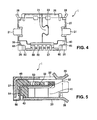
- the shell 20 is made by stamping and bending a metal sheet. More specifically, a projection 21 and a recess 23 are provided on ends of a metal strip so that they are meshed with each other on the bottom of the shell 20 (Fig. 4).
- the housing 40 is inserted into the cylindrical shell 20 from the rear opening. Then, the rear wall 37 of the shell 20 is bent to fix the shell 20 to the housing 40.
- a solder tab 31 is provided on each side of the shell 20 for attachment to the board 70 in Fig. 6.
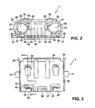
- Tongue portions 25 and 26 of the shell 20 are deformed around the protruded portion 46 of the housing 40 to secure the shell 20 to the housing 40.
- the tongue portions 25 and 26 cover the flat face 43 that extends forward from the lower side 48 and the flat face 45 that extends forward from the lower side 49 (Fig. 2). Consequently, the base portions 32 and 33 are brought into close contact with the flat faces of the protruded portion 46 that extend forward from the upper sides 58 and 59. As a result, the shell 20 is secured to the housing 40 with larger force than before.
- the tongue portions 25 and 26 are deformed on the protruded portion 46 such that the part of the housing 40 is dented or cut by the side edges 35 (Figs. 1 and 3) and 36 (Fig. 4). Consequently, part of the tongue portions 25 and 26 is embedded in the housing 40 so that the shell 20 is secured to the housing 40 better than before.
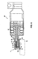
- the tapered portion 42 makes it possible to embed the tongue portion 25 into the housing deeply.
- the area that is indented by the edge 36 of the tongue portion 26 near a boundary 63 between the connector body and the flat face 60 extending from the lower side 49 may be tapered as the tongue portion 25.
- the tongue portions 25 and 26 When the mating connector 80 is plugged in or unplugged from the electrical connector 1, the tongue portions 25 and 26 receive a large force in the plugging direction so that it is necessary for them to be sufficiently strong to endure this force. In this respect, the tongue portions 25 and 26 receive the force in the widthwise or H direction in Fig. 1 so that they are sufficiently strong against it. Consequently, the solder crack between the soldering tab 31 and the board is prevented.
- a terminal 50 is fixed to the housing 40 by integral molding such that the front and rear fixing portions 52 and 54 are fixed to the housing 40 while the intermediate contact portion 53 is exposed in a cavity 41 into which the mating connector is inserted.
- the rear soldering portion 56 is used for connection and fixation to the board 70.
- the terminal support 88 of the mating connector 80 is inserted in the cavity 41.
- the terminal support 88 is guided by the guiding portion 28 of the electrical connector 1 into the cavity 41.
- the contact portion 82 of a plug terminal 82 is brought into contact with the contact portion 53 of the electrical connector 1 while the lock portion 81 of the plug connector 80 is fitted in the engaging hole 22 of the electrical connector 1 so that the plug connector 80 is locked to the receptacle connector 1.
- the lock position is so close to the point where the shell 20 is attached to the housing 40 that the withstanding force upon the plugging in or out operation is enhanced.
- the invention is applicable to other connectors than the electrical connector.
- the position where the housing cover is attached to the housing is located at the rear end of the housing but, as shown in Figs. 7 and 8, it may be at a midway of the housing in the plugging direction.
- the tongue portion is provided at a midway of the housing cover while the housing is provided with an indentation as shown in Fig. 8.
- the invention is useful for a connector with a housing to which a shell is attached.
Landscapes
- Details Of Connecting Devices For Male And Female Coupling (AREA)
- Connector Housings Or Holding Contact Members (AREA)
Applications Claiming Priority (1)
| Application Number | Priority Date | Filing Date | Title |
|---|---|---|---|
| JP2005366908A JP4493590B2 (ja) | 2005-12-20 | 2005-12-20 | コネクタ |
Publications (1)
| Publication Number | Publication Date |
|---|---|
| EP1801933A1 true EP1801933A1 (fr) | 2007-06-27 |
Family
ID=37792289
Family Applications (1)
| Application Number | Title | Priority Date | Filing Date |
|---|---|---|---|
| EP06023824A Withdrawn EP1801933A1 (fr) | 2005-12-20 | 2006-11-16 | Connecteur |
Country Status (6)
| Country | Link |
|---|---|
| US (1) | US7416446B2 (fr) |
| EP (1) | EP1801933A1 (fr) |
| JP (1) | JP4493590B2 (fr) |
| KR (1) | KR20070065838A (fr) |
| CN (1) | CN100561802C (fr) |
| TW (1) | TW200737603A (fr) |
Families Citing this family (12)
| Publication number | Priority date | Publication date | Assignee | Title |
|---|---|---|---|---|
| CN2753007Y (zh) * | 2004-10-22 | 2006-01-18 | 上海莫仕连接器有限公司 | 电连接器 |
| JP5064933B2 (ja) * | 2007-08-20 | 2012-10-31 | 古河電気工業株式会社 | 電気コネクタ |
| JP5050203B2 (ja) * | 2007-09-07 | 2012-10-17 | ヒロセ電機株式会社 | 同軸コネクタと、この同軸コネクタの製造方法 |
| TWM357044U (en) * | 2008-12-03 | 2009-05-11 | Advanced Connectek Inc | Insulating body and electrical connector therewith |
| CN201360060Y (zh) * | 2008-12-22 | 2009-12-09 | 上海莫仕连接器有限公司 | 电连接器 |
| DE102009052786B4 (de) * | 2009-11-11 | 2021-10-21 | Knorr-Bremse Systeme für Nutzfahrzeuge GmbH | Luftaufbereitungsanlage |
| JP2012009358A (ja) * | 2010-06-25 | 2012-01-12 | Jst Mfg Co Ltd | コネクタ用シールドケース及び電気コネクタ |
| JP2012009357A (ja) * | 2010-06-25 | 2012-01-12 | Jst Mfg Co Ltd | 電気コネクタ |
| JP5910682B2 (ja) | 2014-08-08 | 2016-04-27 | Smk株式会社 | 電気コネクタ |
| JP2017045604A (ja) * | 2015-08-26 | 2017-03-02 | タイコエレクトロニクスジャパン合同会社 | シールドコネクタ |
| JP6292201B2 (ja) | 2015-09-18 | 2018-03-14 | Smk株式会社 | 電気コネクタ |
| US11070002B2 (en) * | 2019-01-09 | 2021-07-20 | Amphenol East Asia Limited Taiwan Branch (H.K.) | Connector with guiding portion, and shell and insulating body of the same |
Citations (5)
| Publication number | Priority date | Publication date | Assignee | Title |
|---|---|---|---|---|
| JPH07220814A (ja) | 1994-02-07 | 1995-08-18 | Hosiden Corp | 多極平形コネクタソケット |
| US5980320A (en) | 1997-09-19 | 1999-11-09 | The Whitaker Corporation | Electrical connector having crimped ground shield |
| US20030017744A1 (en) | 2001-07-17 | 2003-01-23 | Stanly Shao | Electrical connector |
| US20040242070A1 (en) | 2003-05-28 | 2004-12-02 | Masashi Inoue | Electrical connector assembly, receptacle connector and plug connector |
| US20050227537A1 (en) | 2004-04-09 | 2005-10-13 | Advanced Connectek Inc. | Electrical connector |
Family Cites Families (4)
| Publication number | Priority date | Publication date | Assignee | Title |
|---|---|---|---|---|
| JP3177774B2 (ja) * | 1997-12-19 | 2001-06-18 | 日本航空電子工業株式会社 | I/oコネクタのシェルとハウジング保持構造 |
| US20070167076A1 (en) * | 2003-09-09 | 2007-07-19 | Seung-Jong Seh | Electrical connector having protective shutter |
| US20050277332A1 (en) * | 2004-06-15 | 2005-12-15 | Marlon Chen | Surface mountable electrical connector |
| US7351105B2 (en) * | 2005-11-09 | 2008-04-01 | Molex Incorporated | Board mounted shielded electrical connector |
-
2005
- 2005-12-20 JP JP2005366908A patent/JP4493590B2/ja not_active Expired - Fee Related
-
2006
- 2006-10-14 TW TW095137919A patent/TW200737603A/zh not_active IP Right Cessation
- 2006-11-09 US US11/594,902 patent/US7416446B2/en not_active Expired - Fee Related
- 2006-11-16 EP EP06023824A patent/EP1801933A1/fr not_active Withdrawn
- 2006-12-19 CN CNB2006101711839A patent/CN100561802C/zh not_active Expired - Fee Related
- 2006-12-20 KR KR1020060130908A patent/KR20070065838A/ko not_active Application Discontinuation
Patent Citations (5)
| Publication number | Priority date | Publication date | Assignee | Title |
|---|---|---|---|---|
| JPH07220814A (ja) | 1994-02-07 | 1995-08-18 | Hosiden Corp | 多極平形コネクタソケット |
| US5980320A (en) | 1997-09-19 | 1999-11-09 | The Whitaker Corporation | Electrical connector having crimped ground shield |
| US20030017744A1 (en) | 2001-07-17 | 2003-01-23 | Stanly Shao | Electrical connector |
| US20040242070A1 (en) | 2003-05-28 | 2004-12-02 | Masashi Inoue | Electrical connector assembly, receptacle connector and plug connector |
| US20050227537A1 (en) | 2004-04-09 | 2005-10-13 | Advanced Connectek Inc. | Electrical connector |
Also Published As
| Publication number | Publication date |
|---|---|
| CN101017943A (zh) | 2007-08-15 |
| TWI324418B (fr) | 2010-05-01 |
| CN100561802C (zh) | 2009-11-18 |
| JP2007172942A (ja) | 2007-07-05 |
| JP4493590B2 (ja) | 2010-06-30 |
| US20070141901A1 (en) | 2007-06-21 |
| TW200737603A (en) | 2007-10-01 |
| US7416446B2 (en) | 2008-08-26 |
| KR20070065838A (ko) | 2007-06-25 |
Similar Documents
| Publication | Publication Date | Title |
|---|---|---|
| US7416446B2 (en) | Connector | |
| US7252549B2 (en) | Connector, receptacle for connector and plug for connector | |
| US6379187B2 (en) | Electrical connector | |
| JP3121388U (ja) | プラグコネクタ及びその組立 | |
| EP1313176B1 (fr) | Connecteur electrique et connecteur de culot | |
| US7134900B2 (en) | Electrical connector assembly with multi-function latching member | |
| KR101044580B1 (ko) | 커넥터 | |
| US20070149054A1 (en) | Electrical connector having flexible mating portion | |
| JP4175657B2 (ja) | コネクタ | |
| US20050118879A1 (en) | Electrical connector | |
| JP2009283357A (ja) | 基板間接続用コネクタ構造 | |
| US6997756B2 (en) | Connector terminal, a connector and a mounting method | |
| JP2009259675A (ja) | 基板間接続用コネクタ構造 | |
| US20060270267A1 (en) | Connector | |
| EP1385232B1 (fr) | Assemblage de connecteur électrique, connecteur à fiche et socle de connecteur | |
| JP4385923B2 (ja) | 端子金具及びこれを用いたコネクタ | |
| EP0797277A2 (fr) | Carte de PC et châssis pour cartes en kit | |
| US7121861B2 (en) | Electrical card connector | |
| JP3067653B2 (ja) | コネクタ | |
| JP2007087902A (ja) | 電気コネクタ | |
| US5655935A (en) | Receptacle contact used in an electrical connector | |
| JP2006100233A (ja) | 端子金具 | |
| JP2007109641A (ja) | 電気コネクタ | |
| JP4093583B2 (ja) | フラットケーブル用電気コネクタ | |
| JP2003338342A (ja) | プリント配線板用コネクタ |
Legal Events
| Date | Code | Title | Description |
|---|---|---|---|
| PUAI | Public reference made under article 153(3) epc to a published international application that has entered the european phase |
Free format text: ORIGINAL CODE: 0009012 |
|
| AK | Designated contracting states |
Kind code of ref document: A1 Designated state(s): AT BE BG CH CY CZ DE DK EE ES FI FR GB GR HU IE IS IT LI LT LU LV MC NL PL PT RO SE SI SK TR |
|
| AX | Request for extension of the european patent |
Extension state: AL BA HR MK YU |
|
| 17P | Request for examination filed |
Effective date: 20071220 |
|
| 17Q | First examination report despatched |
Effective date: 20080124 |
|
| AKX | Designation fees paid |
Designated state(s): DE FI FR GB IT |
|
| GRAP | Despatch of communication of intention to grant a patent |
Free format text: ORIGINAL CODE: EPIDOSNIGR1 |
|
| GRAJ | Information related to disapproval of communication of intention to grant by the applicant or resumption of examination proceedings by the epo deleted |
Free format text: ORIGINAL CODE: EPIDOSDIGR1 |
|
| GRAP | Despatch of communication of intention to grant a patent |
Free format text: ORIGINAL CODE: EPIDOSNIGR1 |
|
| STAA | Information on the status of an ep patent application or granted ep patent |
Free format text: STATUS: THE APPLICATION IS DEEMED TO BE WITHDRAWN |
|
| 18D | Application deemed to be withdrawn |
Effective date: 20100820 |