EP1801253A1 - Steel for high strength spring, and high strength spring and method for manufacture thereof - Google Patents
Steel for high strength spring, and high strength spring and method for manufacture thereof Download PDFInfo
- Publication number
- EP1801253A1 EP1801253A1 EP04772233A EP04772233A EP1801253A1 EP 1801253 A1 EP1801253 A1 EP 1801253A1 EP 04772233 A EP04772233 A EP 04772233A EP 04772233 A EP04772233 A EP 04772233A EP 1801253 A1 EP1801253 A1 EP 1801253A1
- Authority
- EP
- European Patent Office
- Prior art keywords
- high strength
- spring
- less
- strength spring
- hardness
- Prior art date
- Legal status (The legal status is an assumption and is not a legal conclusion. Google has not performed a legal analysis and makes no representation as to the accuracy of the status listed.)
- Granted
Links
Classifications
-
- F—MECHANICAL ENGINEERING; LIGHTING; HEATING; WEAPONS; BLASTING
- F16—ENGINEERING ELEMENTS AND UNITS; GENERAL MEASURES FOR PRODUCING AND MAINTAINING EFFECTIVE FUNCTIONING OF MACHINES OR INSTALLATIONS; THERMAL INSULATION IN GENERAL
- F16F—SPRINGS; SHOCK-ABSORBERS; MEANS FOR DAMPING VIBRATION
- F16F1/00—Springs
- F16F1/02—Springs made of steel or other material having low internal friction; Wound, torsion, leaf, cup, ring or the like springs, the material of the spring not being relevant
- F16F1/021—Springs made of steel or other material having low internal friction; Wound, torsion, leaf, cup, ring or the like springs, the material of the spring not being relevant characterised by their composition, e.g. comprising materials providing for particular spring properties
-
- B—PERFORMING OPERATIONS; TRANSPORTING
- B24—GRINDING; POLISHING
- B24C—ABRASIVE OR RELATED BLASTING WITH PARTICULATE MATERIAL
- B24C1/00—Methods for use of abrasive blasting for producing particular effects; Use of auxiliary equipment in connection with such methods
- B24C1/10—Methods for use of abrasive blasting for producing particular effects; Use of auxiliary equipment in connection with such methods for compacting surfaces, e.g. shot-peening
-
- C—CHEMISTRY; METALLURGY
- C22—METALLURGY; FERROUS OR NON-FERROUS ALLOYS; TREATMENT OF ALLOYS OR NON-FERROUS METALS
- C22C—ALLOYS
- C22C38/00—Ferrous alloys, e.g. steel alloys
- C22C38/04—Ferrous alloys, e.g. steel alloys containing manganese
-
- C—CHEMISTRY; METALLURGY
- C22—METALLURGY; FERROUS OR NON-FERROUS ALLOYS; TREATMENT OF ALLOYS OR NON-FERROUS METALS
- C22C—ALLOYS
- C22C38/00—Ferrous alloys, e.g. steel alloys
- C22C38/06—Ferrous alloys, e.g. steel alloys containing aluminium
-
- C—CHEMISTRY; METALLURGY
- C22—METALLURGY; FERROUS OR NON-FERROUS ALLOYS; TREATMENT OF ALLOYS OR NON-FERROUS METALS
- C22C—ALLOYS
- C22C38/00—Ferrous alloys, e.g. steel alloys
- C22C38/18—Ferrous alloys, e.g. steel alloys containing chromium
- C22C38/34—Ferrous alloys, e.g. steel alloys containing chromium with more than 1.5% by weight of silicon
-
- C—CHEMISTRY; METALLURGY
- C22—METALLURGY; FERROUS OR NON-FERROUS ALLOYS; TREATMENT OF ALLOYS OR NON-FERROUS METALS
- C22C—ALLOYS
- C22C38/00—Ferrous alloys, e.g. steel alloys
- C22C38/18—Ferrous alloys, e.g. steel alloys containing chromium
- C22C38/40—Ferrous alloys, e.g. steel alloys containing chromium with nickel
- C22C38/42—Ferrous alloys, e.g. steel alloys containing chromium with nickel with copper
-
- C—CHEMISTRY; METALLURGY
- C22—METALLURGY; FERROUS OR NON-FERROUS ALLOYS; TREATMENT OF ALLOYS OR NON-FERROUS METALS
- C22C—ALLOYS
- C22C38/00—Ferrous alloys, e.g. steel alloys
- C22C38/18—Ferrous alloys, e.g. steel alloys containing chromium
- C22C38/40—Ferrous alloys, e.g. steel alloys containing chromium with nickel
- C22C38/50—Ferrous alloys, e.g. steel alloys containing chromium with nickel with titanium or zirconium
Definitions
- the present invention relates to a high strength spring steel, high strength springs and manufacturing method thereof.
- the reduction in weight of the spring can be achieved by increasing design stress of the spring.
- the design stress is determined by permanent setting resistance and durability, and these characteristics can be improved by the following means. Improvement in the permanent setting resistance can be realized, from a material viewpoint by use of a steel grade (SUP7) having a increased amount of Si as ferrite strengthening element, or a steel grade (SUP12V) having V additionally as grain refining element, or from a processing viewpoint by conducting setting. On the other hand, improvement in the durability can be realized by increasing carbon and alloying elements so as to increase hardness after tempering from the material viewpoint, or by shot peening so as to give compression residual stress from the processing viewpoint.
- SUP7 steel grade
- SUP12V steel grade having V additionally as grain refining element
- the increase in the strength can only be achieved up to HRC52 in spring hardness and 1900MPa in tensile strength from the durability viewpoint. That is, if the strength of the spring is intensified, the fracture toughness decreases so that the notch sensitivity increases thereby resulting in dispersion in durability and decrease in reliability. Further, it is also a problem that inclusions acting as notches decrease the durability. Further, there are also other problems such that adding any special element costs high in order to prevent decrease in fracture toughness, or that adding a large amount of alloy elements increases hardness after hot rolling so that cracking or breaking of wire occurs when wire is drawn.
- the present invention has been achieved in views of the above-described circumferences and an object of the present invention is to provide a high strength spring steel which has an excellent durability and can be manufactured for practical purposes even when its spring hardness is increased to higher than HRC52 in order to enhance the permanent setting resistance, and high strength spring and manufacturing method thereof.
- the invention provides a high strength spring steel containing in percent of mass, C: 0.36-0.48%, Si: 1.80-2.80%, Mn: 0.20-1.40%, P: 0.015% or less, S: 0.010% or less, Cu: 0.10-0.50%, Ni: 0.10-2.00%, Cr: 0.05-1.20%, s-Al: 0.005-0.040%, N: 0.002-0.012%, O: 0.002% or less while the remainder is constituted of Fe and inevitable impurities, wherein following equations (1), (2), (3) are satisfied and the quantity of inclusions of 10 ⁇ m or larger in diameter per field of vision of 100mm 2 is 10 or less: 1.2 % ⁇ C % + Mn % + Cr % ⁇ 2.0 % 1.4 % ⁇ Si % / 3 + Cr % / 2 + Mn % ⁇ 2.4 % 0.4 % ⁇ Cu % + Ni %
- the high strength spring steel has following three features when classified largely. First, hardness thereof after quenching and tempering is adjusted to HRC52 or higher while suppressing the hardness after rolling, by addition and adjustment of components such as Si, Mn, Cr or the like.
- the quantity of inclusions (particularly inclusion of oxides) having a diameter of 10 ⁇ m or larger, which can become an origin of fracture, is reduced by deoxidizing sufficiently (more specifically deoxidizing by Al) thereby providing high fatigue strength.
- the corrosion fatigue strength is enhanced by adding and adjusting anticorrosive elements such as Cu and Ni, and by optimizing the quantity of corrosion accelerating elements.
- a high strength spring steel having an excellent durability is realized even if the hardness is as high as HRC52 or higher. Then, a high strength spring having a maximum shearing stress of 1176MPa or more is achieved by performing warm peening on such a high strength spring steel as described later.
- C is effective for obtaining a predetermined strength by annealing.
- C of 0.36% or more needs to be added.
- C is added at 0.38% or more.
- the upper limit is set to 0.48%.
- it is 0.46%.
- Si is effective for improving corrosion fatigue strength and permanent setting resistance. For that purpose, it needs to be added at 1.8% or larger. On the other hand, because excessive addition lowers the toughness, deteriorates the fatigue characteristic and accelerates generation of decarburization thereby worsening workability, its upper limit is set to 2.80%. Preferably, it is set to 2.60%.
- Mn is effective as deoxidizing agent at the time of melting and contributes to improvement of hardenability. Further, it has an effect of rendering harmful effect of S invalid. In order to obtain these effects, Mn needs to be added at 0.20% or larger.
- Mn since excessive addition not only accelerates oxidization of grain boundary at the time of quenching thereby inducing embrittlement but also intensifies hardness of wire material after rolling deteriorating workability of the wire, its upper limit is set to 1.40%. Preferably, it is set to 1.10%.
- the upper limit of phosphor is set to 0.015% because phosphor is segregated in austenite grain boundary at the time of heating for austenitizing so that the grain boundary is embrittled.
- Cu is effective for intensifying resistance to corrosion, thereby enhancing corrosion fatigue strength. Further, it is effective for preventing decarburization of ferrite. In order to obtain these effects, it needs to be added at 0.10% or larger. On the other hand, because excessive addition damages hot workability, the upper limit thereof is set to 0.50%. Preferably, it is set to 0.40%.
- Ni is effective for intensifying resistance to corrosion thereby enhancing corrosion fatigue strength. Further, it is effective for preventing decarburization of ferrite. In order to obtain these effects, it needs to be added at 0.10% or more. On the other hand, because excessive addition induces increase in cost, the upper limit thereof is set to 2.00%. Preferably, it is set to 1.80%. Further, according to the present invention, Cu and Ni need to be added together so that the total amount thereof is 0.4% or more for the corrosion fatigue strength not to deteriorate as described later.
- Cr is an element which contributes to improvement of hardenability. For that purpose, it needs to be added at 0.05% or larger. On the other hand, excessive addition intensifies hardness of wire material after rolling and deteriorates workability of the wire material. Further, carbide of Cr turns into a local electrode on the surface of steel to increase a corrosion pit so that the corrosion fatigue strength decreases. Therefore, the upper limit thereof is set to 1.20%. Preferably, it is set to 1.1%.
- Al(aluminum) is a deoxidizing element and the s-Al needs to be added at 0.005% or more to obtain its effect.
- the upper limit thereof is set to 0.040%.
- it is set to 0.030%.
- the s-Al means Al soluble in acid.
- N has an effect of forming carbonitride and nitride which contributes to refinement of crystal grain in steel. In order to obtain this effect, it needs to be contained at 0.002% or more. On the other hand, since excessive addition generates bulky pieces of Nb carbonitride so that preventing effect of grain coarsening can not be obtained and generates TiN type inclusions thereby inducing decrease of fatigue strength, the upper limit thereof is set to 0.012%.
- C(%) + Mn(%) + Cr(%) needs to be 1.2% or larger. Preferably, it is set to 1.3% or more. On the other hand, if C(%) + Mn(%) + Cr (%) exceeds 2.0%, the steel hardens too much after rolling so that breaking or surface flaw occurs at the time of drawing. Preferably, it is set to 1.9% or less.
- * 1.4 % ⁇ Si % / 3 + Cr % / 2 + Mn % ⁇ 2.4 % [in case where B is added as described later: 1.4% ⁇ Si(%)/3 + Cr(%)/2 + Mn(%) + 170B(%) ⁇ 2.4% ... equation (2)']
- Si(%)/3 + Cr(%)/2 + Mn(%) also needs to be 1.4% or more. Preferably, it is set to 1.5% or more. On the other hand, if Si(%)/3 + Cr(%)/2 + Mn(%) exceeds 2.4%, the hardenability is intensified excessively so that crack occurs at the time of quenching. Preferably, it is set to 2.1% or less. * 0.4 % ⁇ Cu % + Ni %
- Cu(%) + Ni(%) needs to be 0.4% or larger in order to secure fatigue characteristic under corrosive environment.
- the high strength spring steel of the present invention can contain one or more of Ti: 0.020-0.070%, Nb: 0.020-0.050% and B: 0.0005-0.0030% as well as the above-described steel components.
- B the equation (2) is replaced with a following equation (2)'. 1.4 % ⁇ Si % / 3 + Cr % / 2 + Mn % + 170 ⁇ B % ⁇ 2.4 %
- the high strength spring steel of the present invention is characterized in containing, in percent of mass, of: C: 0.36-0.48%; Si: 1.80-2.80%; Mn: 0.20-1.40%; P: 0.015% or less; S: 0.010% or less; Cu: 0.10-0.50%; Ni: 0.10-2.00%; Cr: 0.05-1.20%; s-Al: 0.005-0.040%; N: 0.002-0.012%; O: 0.002% or less, while further one or more of Ti: 0.020-0.070%; Nb: 0.020-0.050%; B: 0.0005-0.0030% are contained and the remainder is constituted of Fe and inevitable impurities, wherein following equations (1), (2)', (3) are satisfied and the quantity of inclusions of 10 ⁇ m or larger in diameter per field of vision of 100mm 2 is 10 or less: 1.2 % ⁇ C % + Mn % + Cr % ⁇ 2.0 % 1.4 % ⁇ Si % / 3 + Cr % / 2 + Mn
- Ti forms carbonitride in steel and refines austenite grain, and contributes to precipitation hardening. In order to obtain this effect, it is preferable to be added at 0.020% or more. On the other hand, because excessive addition allows it to be left as a relatively large non-dissolved compound when steel is heated for quenching and can become an origin of fracture thereby reducing fatigue strength, preferably, it is set to 0.070% or less.
- Nb contributes to refinement of crystal grain and precipitation hardening and has an effect of enhancing permanent setting resistance. In order to obtain this effect, it is preferable to be added at 0.020% or larger. On the other hand, because excessive addition saturates its effect and lowers hot and cold workability, it is preferable to be added at 0.050% or less.
- B precipitates with preference at crystal grain boundary thereby preventing segregation of P and S at the crystal grain boundary and enhancing fatigue strength and delayed fracture property. In order to obtain this effect, it is preferable to be added at 0.0005% or more. On the other hand, since excessive addition forms B nitride thereby damaging toughness of steel and deteriorating fatigue characteristics, it is preferable to be added at 0.0030% or less. If B is added as described above, the aforementioned equation (2)' needs to be satisfied.
- the high strength spring steel of the present invention may further contain one or two of Mo: 0.01-0.50% and V: 0.05-0.30% as steel components.
- Mo is an element which contributes to improvement of hardenability. It is an element which intensifies corrosion resistance, thereby enhancing corrosion fatigue strength. In order to obtain these effects, it is preferable to be added at 0.01% or more. On the other hand, since excessive addition generates bainite in wire material after rolling and can induce deterioration of cold workability, it is preferable to be 0.50% or less. More preferably, it is set to 0.40%.
- V contributes to refinement of crystal grain and precipitation hardening, thereby enhancing permanent setting resistance. In order to obtain this effect, it is preferable to be added at 0.05% or more. On the other hand, because excessive addition turns V carbide to a local electrode on the surface of steel thereby forming a corrosion pit so that it can become an origin of cracking fracture, it is preferable to be added at 0.30% or less. Further, excessive addition can crystallize bulky pieces of primary carbide thereby possibly deteriorating cold workability.
- the manufacturing method of high strength spring of the present invention is characterized in that the high strength spring steel which is tempered to HRC52 or higher is formed into a spring shape by hot forming or cold forming, and warm shot peening is carried out, so as to produce a high strength spring of 1176 MPa or higher in maximum shearing stress.
- the magnitude of residual stress distribution by shot peening is related to deformation characteristics of the material, and for example, for the same tensile strength, a material having a smaller yield ratio (yield stress/tensile strength) can obtain a larger compressive residual stress by shot peening.
- warm shot peening WSP is performed on a formed spring steel.
- the warm shot peening is a method of carrying out the shot peening in a warm temperature range of 150°C - 350°C.
- the yield point at the time of shot peening of spring steel decreases so that a sufficient compressive residual stress is obtained and finally the fatigue strength and corrosion fatigue strength of the spring are enhanced.
- the warm shot peening is preferred to be carried out in a temperature range of 200-350°C.
- the quantity of C in the high strength spring steel of the present invention is lower as described above, and thus its yield ratio is small so that a sufficient compressive residual stress can be obtained by shot peening. Further, since the quantity of C is low so that a larger deformation can be introduced, improvement in hardness in the vicinity of the surface by dynamic strain aging is achieved, thereby securing an excellent fatigue strength enhancing effect.
- the ordinary shot peening has such a problem that an expensive SP material with high hardness needs to be used because the shot peening (SP) material is easy to crack.
- a high strength spring having hardness tempered to HRC52 or higher while its maximum shearing stress is 1176MPa or higher can be obtained, provided with an excellent durability due to a sufficient compressive residual stress.
- a high strength spring can be employed preferably for a coil spring, leaf spring, torsion bar, stabilizer and the like used in an automobile suspension unit or the like.
- the rod rolling was performed at a rolling end temperature of 869°C with the steel heated at 1100°C.
- the rolled material was cooled down with air after the rolling was finished.
- Table 2 shows values of C(%) + Mn(%) + Cr(%), Si(%)/3 + Cr(%)/2 + Mn(%), Cu(%) + Ni(%).
- ⁇ downward arrow
- ⁇ upward arrow
- Table 2 shows a result of the evaluations.
- Hardness of the rolled wire material was measured in its cut section.
- Rockwell C scale hardness was measured at 30 points and an average hardness plus 6 times of standard deviation ⁇ (dispersion) was regarded as "hardness after rolling". For determination on whether the hardness after rolling was acceptable, HRC35 was set to be an upper limit.
- the rolled wire material of 13mm in diameter was phosphated and cold drawn to 12mm in diameter so as to obtain a drawn material. Presence or absence of breaking upon drawing processing was evaluated.
- the drawn material was heated at 900°C or higher, it was quenched by water cooling immediately so as to obtain a quenched material. Presence or absence of crack was evaluated on the quenched material.
- Hardness of a core portion in the section of the quenched material was measured.
- Rockwell C scale hardness was measured at 20 points and whether or not an average hardness satisfies a predetermined hardness (more than 52HRC) was evaluated.
- the quantity of oxide type inclusions of 10 ⁇ m or larger in diameter in the drawn material per 100mm 2 was evaluated.
- test piece was cut out from the drawn material of 20mm in diameter and quenched from 900°C or higher and tempered to 54HRC to obtain a fatigue test piece. ONO type rotating bending fatigue test was performed using the test piece so as to evaluate the fatigue strength.
- a tempered material having hardness of HRC52 was obtained.
- reversed torsion fatigue test was performed with stress amplitude set to 700 MPa. Corrosion fatigue property was evaluated with the number of repetitions until fracture. In the meantime, whether or not the number of repetitions until fracture reached 100,000 was adopted as a criterion for determining whether or not the property was acceptable.
- Depth of corrosion pit was measured at 40 points in a section of a corroded portion after the fatigue test so as to measure a maximum value (maximum pit depth) of a pit depth. Whether or not the maximum pitch depth was 100 ⁇ m or larger was adopted as a criterion for determining whether or not the pit depth was acceptable. Table 3 shows a relation between the corrosion pit depth and the number of repetitions until fracture.
- the comparative examples 13-15 were short in the value of C(%) + Mn(%) + Cr(%)to the range specified by the invention, and the comparative examples 15-17 were short in the value of Si(%)/3 + Cr(%)/2 + Mn(%) + 170B(%) (also, the comparative example 13 is short in the quantity of C, the comparative example 14 is short in the quantity of Cr, the comparative example 15 is short in the quantity of Mn and the comparative example 16 is short in the quantity of Si) and (4) hardness after quenching was lower than HRC52 and the strength and hardenability were insufficient.
- the comparative examples 18 and 19 were excessive in the value of Si(%)/3 + Cr(%)/2 + Mn(%) + 170B (%) to the range specified by the present invention, so that (3) quench crack occurred at the time of quenching.
- the comparative example 20 exceeded the range specified by the present invention in the quantity of Al, the comparative example 21 was excessive in the quantity of O, the comparative example 22 was excessive in the quantity of P, S, Al and O and (5) the quantity of inclusions was 10 or more while (6) the fatigue strength was insufficient. Further, (7) the corrosion fatigue strength was insufficient also.
- the comparative example 23 exceeded the range specified by the present invention in the quantity of C , the comparative example 24 was excessive in the quantity of Si, the comparative example 25 was excessive in the quantity of Cr, the comparative example 26 was short in the quantity of Cu, the comparative example 27 was short in the quantity of Ni, the comparative example 28 was short in the value of Cu (%) + Ni (%), (8) the depth of corrosion pit is greater than 100 ⁇ m and (7) the corrosion fatigue strength was insufficient.
- a coil spring obtained by performing warm shot peening on a spring steel in the range specified by the invention described above, in which an excellent fatigue strength, corrosion fatigue strength, and permanent setting resistance are achieved will be shown as an example.
- a cold forming method and a hot forming method are available as a spring forming method, a coil spring having such characteristics was obtained in both of the methods.
- the example A is a cold formed spring and the example B is a hot formed spring.
- the temperature condition of the warm spot peening was set to 250°C.
- a spring obtained by cold forming a conventional steel (SUP7) was used as a comparative example.
- Table 4 shows compositions of high strength spring steel of the present invention used in the examples A, B and the conventional steel (SUP7) used in the comparative example.
- material C Si Mn P S Cu Ni Cr Ti Nb B Al N 0 C+Mn+Cr Si/3+Cr/2+Mn+170B Cu+Ni example A 0.39 2.19 0.85 0.008 0.001 0.28 0.16 0.13 - - - 0.014 0.009 0.0011 1.37 1.65 0.44 example B 0.44 2.50 0.98 0.011 0.002 0.28 0.78 0.58 0.037 0,036 0.0016 0.021 0.007 0.0011 2.00 2.38 1,06 comparative example (SUP7) ⁇ 0,60 2.00 0.93 0.012 0.008 ⁇ ⁇ 0.01 ⁇ - 0.15 - - - 0.015 0.009 0.009 1.68 1.67 0.01 or less
- the spring hardness was set to 52HRC and 54HRC. This is due to a following reason.
- the hardness of the spring varies in a certain range due to components and inevitable changes in tempering temperature.
- experiments were performed in a range from 52HRC to 54HRC as upper and lower limits.
- the fatigue strength and permanent setting property not relating to corrosion are higher as the hardness of the spring increases.
- the corrosion fatigue strength is lower as the hardness of the spring increases. Therefore, in order to achieve sufficient fatigue strength, permanent setting property and corrosion fatigue strength under a design stress of 1176MPa, the fatigue strength and permanent setting property need to be satisfied even if the hardness is lower and the corrosion fatigue strength needs to be improved even if the hardness is higher.
- the fatigue strength and permanent setting property were compared with that of the conventional steel SUP7 having hardness of 49HRC and 54HRC. Further, the corrosion fatigue strength was compared with the conventional steel SUP7 having hardness of 51HRC.
- the tightening test is carried out in a following procedure.
- a load P1 is applied to the coil spring with a load testing machine so as to generate a predetermined shearing stress, for example, 1176MPa so that the spring is allowed to deflect up to a corresponding height H. With this condition, the height of the spring is constrained with a jig.
- the spring is heated at a predetermined temperature in a predetermined interval of time , at 80°C for 96 hours in this test, so as to generate creep deformation in the spring.
- Table 6 shows a comparison of the permanent setting property in the tightening test between the examples and the comparative examples.
- the example A having hardness of 52HRC indicates an far more better permanent setting property than the comparative example (SUP7) having lower hardness of 49 HRC. Further, it indicates a substantially equal permanent setting property under all tightening stresses as compared with the SUP7 having hardness of 54HRC, that is higher than the example A. Further, the example B having hardness of 52HRC indicates an excellent permanent setting property as compared to the SUP7 of the 54HRC having higher hardness.
- the corrosion fatigue test was carried out in a following procedure.
- the comparative example SUP7 has hardness of 51HRC and the vibration condition is 735 ⁇ 395MPa.
- the number of repetitions of endurance is 59,000 times.
- the number of repetitions of endurance is equal or higher than the comparative example, that is, 60,000 times although its hardness is 54HRC and test stress is 735 ⁇ 490MPa.
- the example B indicated an excellent corrosion fatigue strength as the number of repetitions of endurance is 74, 000 times under the condition in which the hardness is 54HRC and the test condition is 735 ⁇ 490MPa.
Landscapes
- Chemical & Material Sciences (AREA)
- Engineering & Computer Science (AREA)
- Mechanical Engineering (AREA)
- Materials Engineering (AREA)
- Metallurgy (AREA)
- Organic Chemistry (AREA)
- General Engineering & Computer Science (AREA)
- Heat Treatment Of Articles (AREA)
- Heat Treatment Of Steel (AREA)
- Springs (AREA)
Abstract
Description
- This application is word-for-word translation of PCT Patent Application No.
PCT/JP2004/012277 filed on August 26, 2004 - The present invention relates to a high strength spring steel, high strength springs and manufacturing method thereof.
- In recent years, reduction in amount of emission of carbon dioxide gas has been considered as a problem to be solved from a viewpoint of suppressing global warming. Thus, reduction in weight of a vehicle resulting in enhancement of fuel efficiency has been regarded important in a field of automobiles, so that reduction in weight of a variety of springs such as a suspension coil spring has been sought after. In order to achieve reduction in weight of the spring while maintaining required spring characteristics, it is required to have a high strength spring having design stress, τmax of 1176 MPa or higher and hardness of HRC52 or higher at Rockwell hardness C scale.
- By the way, the reduction in weight of the spring can be achieved by increasing design stress of the spring. The design stress is determined by permanent setting resistance and durability, and these characteristics can be improved by the following means. Improvement in the permanent setting resistance can be realized, from a material viewpoint by use of a steel grade (SUP7) having a increased amount of Si as ferrite strengthening element, or a steel grade (SUP12V) having V additionally as grain refining element, or from a processing viewpoint by conducting setting. On the other hand, improvement in the durability can be realized by increasing carbon and alloying elements so as to increase hardness after tempering from the material viewpoint, or by shot peening so as to give compression residual stress from the processing viewpoint.
- However, conventionally, even if the above-described means is used, the increase in the strength can only be achieved up to HRC52 in spring hardness and 1900MPa in tensile strength from the durability viewpoint. That is, if the strength of the spring is intensified, the fracture toughness decreases so that the notch sensitivity increases thereby resulting in dispersion in durability and decrease in reliability. Further, it is also a problem that inclusions acting as notches decrease the durability. Further, there are also other problems such that adding any special element costs high in order to prevent decrease in fracture toughness, or that adding a large amount of alloy elements increases hardness after hot rolling so that cracking or breaking of wire occurs when wire is drawn.
- On the other hand, in recent years, a snow melting agent constituted mainly of chloride has been sprayed so as to prevent road surface from being frozen in winter season, and thus enhancement of corrosion fatigue strength has become an important problem to be solved. However, in conventional spring steels such as SUP7 and SAE9254, increasing the hardness leads to decrease in corrosion fatigue strength and in conventional steel, there is a limit in increasing the hardness more than a current level. In a spring used under a corrosion environment, a corrosion pit serves as a notch thereby inducing decrease in corrosion fatigue strength. Even if an anti-corrosive element is added for purposes of preventing the aforementioned phenomenon, increase in hardness is induced after rolling so that workability decreases.
- If the hardness of a spring is higher than that of a shot peening (SP) material, compressive residual stress which contributes largely to the enhancement of fatigue strength is not loaded sufficiently. Additionally, there are other problems such that the SP material becomes easy to break thereby leading to higher cost, and that crashed grains stick into a spring thereby reducing its durability.
- The present invention has been achieved in views of the above-described circumferences and an object of the present invention is to provide a high strength spring steel which has an excellent durability and can be manufactured for practical purposes even when its spring hardness is increased to higher than HRC52 in order to enhance the permanent setting resistance, and high strength spring and manufacturing method thereof.
- Patent document 1:
Japanese Patent Application Publication No.3064672 - To achieve the object above, the invention provides a high strength spring steel containing in percent of mass, C: 0.36-0.48%, Si: 1.80-2.80%, Mn: 0.20-1.40%, P: 0.015% or less, S: 0.010% or less, Cu: 0.10-0.50%, Ni: 0.10-2.00%, Cr: 0.05-1.20%, s-Al: 0.005-0.040%, N: 0.002-0.012%, O: 0.002% or less while the remainder is constituted of Fe and inevitable impurities, wherein following equations (1), (2), (3) are satisfied and the quantity of inclusions of 10µm or larger in diameter per field of vision of 100mm2 is 10 or less:


- The high strength spring steel has following three features when classified largely. First, hardness thereof after quenching and tempering is adjusted to HRC52 or higher while suppressing the hardness after rolling, by addition and adjustment of components such as Si, Mn, Cr or the like.
- Secondly, the quantity of inclusions (particularly inclusion of oxides) having a diameter of 10 µm or larger, which can become an origin of fracture, is reduced by deoxidizing sufficiently (more specifically deoxidizing by Al) thereby providing high fatigue strength.
- Thirdly, the corrosion fatigue strength is enhanced by adding and adjusting anticorrosive elements such as Cu and Ni, and by optimizing the quantity of corrosion accelerating elements.
- In the above-described manner, a high strength spring steel having an excellent durability is realized even if the hardness is as high as HRC52 or higher. Then, a high strength spring having a maximum shearing stress of 1176MPa or more is achieved by performing warm peening on such a high strength spring steel as described later.
- Hereinafter, the present invention will be explained more in detail by describing the reasons for each numerical limitation.
- C is effective for obtaining a predetermined strength by annealing. For that purpose, C of 0.36% or more needs to be added. Preferably, C is added at 0.38% or more. On the other hand, since excessive addition lowers toughness after annealing and deteriorates fatigue strength and corrosion fatigue strength and the hardness after rolling is intensified too much so as to reduce cold workability, the upper limit is set to 0.48%. Preferably, it is 0.46%.
- Si is effective for improving corrosion fatigue strength and permanent setting resistance. For that purpose, it needs to be added at 1.8% or larger. On the other hand, because excessive addition lowers the toughness, deteriorates the fatigue characteristic and accelerates generation of decarburization thereby worsening workability, its upper limit is set to 2.80%. Preferably, it is set to 2.60%.
- Mn is effective as deoxidizing agent at the time of melting and contributes to improvement of hardenability. Further, it has an effect of rendering harmful effect of S invalid. In order to obtain these effects, Mn needs to be added at 0.20% or larger. On the other hand, since excessive addition not only accelerates oxidization of grain boundary at the time of quenching thereby inducing embrittlement but also intensifies hardness of wire material after rolling deteriorating workability of the wire, its upper limit is set to 1.40%. Preferably, it is set to 1.10%.
- The upper limit of phosphor is set to 0.015% because phosphor is segregated in austenite grain boundary at the time of heating for austenitizing so that the grain boundary is embrittled.
- The upper limit of sulfur is set to 0.010% because sulfur embrittles austenite grain boundary like phosphor and forms MnS to induce deterioration of fatigue strength of the spring.
- Cu is effective for intensifying resistance to corrosion, thereby enhancing corrosion fatigue strength. Further, it is effective for preventing decarburization of ferrite. In order to obtain these effects, it needs to be added at 0.10% or larger. On the other hand, because excessive addition damages hot workability, the upper limit thereof is set to 0.50%. Preferably, it is set to 0.40%.
- Ni is effective for intensifying resistance to corrosion thereby enhancing corrosion fatigue strength. Further, it is effective for preventing decarburization of ferrite. In order to obtain these effects, it needs to be added at 0.10% or more. On the other hand, because excessive addition induces increase in cost, the upper limit thereof is set to 2.00%. Preferably, it is set to 1.80%. Further, according to the present invention, Cu and Ni need to be added together so that the total amount thereof is 0.4% or more for the corrosion fatigue strength not to deteriorate as described later.
- Cr is an element which contributes to improvement of hardenability. For that purpose, it needs to be added at 0.05% or larger. On the other hand, excessive addition intensifies hardness of wire material after rolling and deteriorates workability of the wire material. Further, carbide of Cr turns into a local electrode on the surface of steel to increase a corrosion pit so that the corrosion fatigue strength decreases. Therefore, the upper limit thereof is set to 1.20%. Preferably, it is set to 1.1%.
- Al(aluminum) is a deoxidizing element and the s-Al needs to be added at 0.005% or more to obtain its effect. On the other hand, because excessive addition results in generation of sand mark and increases the quantity of oxide type inclusions in steel thereby damaging cleanliness of the steel so that it becomes an origin of fatigue fracture, the upper limit thereof is set to 0.040%. Preferably, it is set to 0.030%. Here, the s-Al means Al soluble in acid.
- N has an effect of forming carbonitride and nitride which contributes to refinement of crystal grain in steel. In order to obtain this effect, it needs to be contained at 0.002% or more. On the other hand, since excessive addition generates bulky pieces of Nb carbonitride so that preventing effect of grain coarsening can not be obtained and generates TiN type inclusions thereby inducing decrease of fatigue strength, the upper limit thereof is set to 0.012%.
- Because O generates oxide type inclusions and likely becomes an origin of fatigue fracture, the upper limit thereof is set to 0.002 %. In the meantime, sufficient Al deoxidizing is needed to suppress the content of O to this level.

- To secure a hardness of HRC52 or higher in Rockwell hardness, C(%) + Mn(%) + Cr(%) needs to be 1.2% or larger. Preferably, it is set to 1.3% or more. On the other hand, if C(%) + Mn(%) + Cr (%) exceeds 2.0%, the steel hardens too much after rolling so that breaking or surface flaw occurs at the time of drawing. Preferably, it is set to 1.9% or less.

- To provide hardenability capable of securing hardness of HRC52 or higher at a core portion of wire material, Si(%)/3 + Cr(%)/2 + Mn(%) also needs to be 1.4% or more. Preferably, it is set to 1.5% or more. On the other hand, if Si(%)/3 + Cr(%)/2 + Mn(%) exceeds 2.4%, the hardenability is intensified excessively so that crack occurs at the time of quenching. Preferably, it is set to 2.1% or less.

- In the high strength spring having hardness of HRC52 or higher, Cu(%) + Ni(%) needs to be 0.4% or larger in order to secure fatigue characteristic under corrosive environment.
- * The quantity of inclusions (oxide type inclusions) having a diameter of 10µm or more is 10 or less per field of vision of 100mm2.
- If 10 or more inclusions (oxide type inclusions) having a diameter of 10µm or more exist per field of vision of 100mm2, the fatigue strength decreases because the inclusion in steel turns to an origin of fatigue fracture. Particularly, high strength materials having hardness of HRC52 or higher are affected strongly by the inclusions.
- Next, the high strength spring steel of the present invention can contain one or more of Ti: 0.020-0.070%, Nb: 0.020-0.050% and B: 0.0005-0.0030% as well as the above-described steel components. When B is contained, the equation (2) is replaced with a following equation (2)'.

- That is, the high strength spring steel of the present invention is characterized in containing, in percent of mass, of: C: 0.36-0.48%; Si: 1.80-2.80%; Mn: 0.20-1.40%; P: 0.015% or less; S: 0.010% or less; Cu: 0.10-0.50%; Ni: 0.10-2.00%; Cr: 0.05-1.20%; s-Al: 0.005-0.040%; N: 0.002-0.012%; O: 0.002% or less, while further one or more of Ti: 0.020-0.070%; Nb: 0.020-0.050%; B: 0.0005-0.0030% are contained and the remainder is constituted of Fe and inevitable impurities, wherein following equations (1), (2)', (3) are satisfied and the quantity of inclusions of 10µm or larger in diameter per field of vision of 100mm2 is 10 or less:


- Ti forms carbonitride in steel and refines austenite grain, and contributes to precipitation hardening. In order to obtain this effect, it is preferable to be added at 0.020% or more. On the other hand, because excessive addition allows it to be left as a relatively large non-dissolved compound when steel is heated for quenching and can become an origin of fracture thereby reducing fatigue strength, preferably, it is set to 0.070% or less.
- Nb contributes to refinement of crystal grain and precipitation hardening and has an effect of enhancing permanent setting resistance. In order to obtain this effect, it is preferable to be added at 0.020% or larger. On the other hand, because excessive addition saturates its effect and lowers hot and cold workability, it is preferable to be added at 0.050% or less.
- B precipitates with preference at crystal grain boundary thereby preventing segregation of P and S at the crystal grain boundary and enhancing fatigue strength and delayed fracture property. In order to obtain this effect, it is preferable to be added at 0.0005% or more. On the other hand, since excessive addition forms B nitride thereby damaging toughness of steel and deteriorating fatigue characteristics, it is preferable to be added at 0.0030% or less. If B is added as described above, the aforementioned equation (2)' needs to be satisfied.
- Next, the high strength spring steel of the present invention may further contain one or two of Mo: 0.01-0.50% and V: 0.05-0.30% as steel components.
- Mo is an element which contributes to improvement of hardenability. It is an element which intensifies corrosion resistance, thereby enhancing corrosion fatigue strength. In order to obtain these effects, it is preferable to be added at 0.01% or more. On the other hand, since excessive addition generates bainite in wire material after rolling and can induce deterioration of cold workability, it is preferable to be 0.50% or less. More preferably, it is set to 0.40%.
- V contributes to refinement of crystal grain and precipitation hardening, thereby enhancing permanent setting resistance. In order to obtain this effect, it is preferable to be added at 0.05% or more. On the other hand, because excessive addition turns V carbide to a local electrode on the surface of steel thereby forming a corrosion pit so that it can become an origin of cracking fracture, it is preferable to be added at 0.30% or less. Further, excessive addition can crystallize bulky pieces of primary carbide thereby possibly deteriorating cold workability.
- The manufacturing method of high strength spring of the present invention is characterized in that the high strength spring steel which is tempered to HRC52 or higher is formed into a spring shape by hot forming or cold forming, and warm shot peening is carried out, so as to produce a high strength spring of 1176 MPa or higher in maximum shearing stress.
- It has been widely known that if a large compressive residual stress is generated on the surface of a spring by shot peening processing, the fatigue strength and corrosion fatigue strength of the spring are enhanced. The magnitude of residual stress distribution by shot peening is related to deformation characteristics of the material, and for example, for the same tensile strength, a material having a smaller yield ratio (yield stress/tensile strength) can obtain a larger compressive residual stress by shot peening. Then, in the present invention, warm shot peening (WSP) is performed on a formed spring steel. The warm shot peening is a method of carrying out the shot peening in a warm temperature range of 150°C - 350°C. As a consequence, the yield point at the time of shot peening of spring steel decreases so that a sufficient compressive residual stress is obtained and finally the fatigue strength and corrosion fatigue strength of the spring are enhanced. To intensify this effect further, the warm shot peening is preferred to be carried out in a temperature range of 200-350°C.
- Although in an ordinary spring steel, its C quantity is generally 0.55-0.65%, the quantity of C in the high strength spring steel of the present invention is lower as described above, and thus its yield ratio is small so that a sufficient compressive residual stress can be obtained by shot peening. Further, since the quantity of C is low so that a larger deformation can be introduced, improvement in hardness in the vicinity of the surface by dynamic strain aging is achieved, thereby securing an excellent fatigue strength enhancing effect.
- If the spring has a high strength, the ordinary shot peening has such a problem that an expensive SP material with high hardness needs to be used because the shot peening (SP) material is easy to crack. These problems are solved by carrying out the warm shot peening as mentioned in the invention.
- As described above, according to the present invention, a high strength spring having hardness tempered to HRC52 or higher while its maximum shearing stress is 1176MPa or higher can be obtained, provided with an excellent durability due to a sufficient compressive residual stress. Such a high strength spring can be employed preferably for a coil spring, leaf spring, torsion bar, stabilizer and the like used in an automobile suspension unit or the like.
- Hereinafter, the preferred embodiment of the present invention will be described in detail. Steel ingot obtained by melting, having chemical composition shown in Table 1, was bloomed and rolled to wire rod material having 13mm in diameter and 20mm in diameter. The rod rolling was performed at a rolling end temperature of 869°C with the steel heated at 1100°C. The rolled material was cooled down with air after the rolling was finished.
- Table 2 shows values of C(%) + Mn(%) + Cr(%), Si(%)/3 + Cr(%)/2 + Mn(%), Cu(%) + Ni(%). Of examples deviating from a composition range specified by the present invention in respective compositions in Table, an example which is lower than the lower limit is supplied with a downward arrow (↓) and an example which is higher than the higher limit is supplied with an upward arrow (↑).
[Table 1] C Si Mn P S Cu Ni Cr Mo V Ti Nb Al N B 0 upper limit 0.48 2.80 1.40 0.015 0.01 0.50 2.00 1.20 0.50 0.30 0.070 0.050 0.040 0.012 0.0030 0.0020 lower limit 0.36 1.70 0.20 - - 0.10 0.10 0.10 0.01 0.05 0,020 0.020 0.005 0.002 0.0005 - present invention 1 0.40 2.20 0.83 0.007 0.004 0.29 0.27 0.16 0 0 0 0 0.020 0.007 0 0.0012 present invention 2 0.40 2.19 0.80 0.009 0.003 0.30 0.21 0.13 0 0 0.051 0 0.017 0.007 0.0012 present invention 3 0.39 2.21 0.78 0.010 0.004 0.31 0.24 0.10 0 0 0 0.049 0.021 0.007 0 0.0013 present invention 4 0.39 2.13 0.78 0.015 0.009 0.30 0.11 0.17 0 0 0 0 0.038 0.009 0.0028 0.0011 present invention 5 0.44 2.50 0.98 0.011 0.002 0.28 0.78 0.58 0 0 0.031 0.036 0.021 0.001 0.0016 0.0011 present invention 6 0.48 2.75 0.24 0.013 0.007 0.48 1.95 1.18 0 0.28 0.068 0 0.007 0.012 0 0.0019 present invention 7 0.36 1.72 1.36 0.010 0.004 0.11 0.31 0.20 0.44 0.06 0.021 0 0.018 0.003 0 0.0009 present invention 8 0.41 2.52 0.70 0.014 0.010 0.13 1.75 0.75 0.37 0.18 0.040 0 0.018 0.005 0 0.0011 present invention 9 0.39 1.78 0.20 0.010 0.003 0.27 0.59 0.95 0.02 0.16 0.055 0.022 0.011 0.011 0.0015 0.0008 comparative example 10 0.39 2.75 1.45 0.013 0.004 0.28 0.24 0.55 0 0 0.050 0 0.018 0.012 0 0.0017 comparative example 11 0.48 2.57 0.70 0.014 0.007 0.28 0.25 ↑ 1.27 0 0 0.047 0 0.026 0.009 0 0.0018 comparative example 12 0.37 2.73 0.65 0.009 0.005 0.28 0.25 1.00 0.53 0 0.052 0 0.026 0.009 0 0.0016 comparative example 13 0.35 1.89 0.73 0.011 0.006 0.31 0.26 0.11 0 0 0.050 0 0.023 0.011 0 0,0012 comparative example 14 0.48 2.22 0.65 0.012 0.005 0.29 0.23 0.05 0 0 0.046 0 0.017 0.008 0 0.0009 comparative example 15 0.48 1.70 0.15 0.012 0.005 0.28 0.23 0.55 0 0 0.046 0 0.017 0.008 0 0.0008 comparative example 16 0.47 1.66 0.67 0.011 0.006 0.15 0.20 0.19 0 0 0.050 0 0.015 0.006 0 0.0012 comparative example 17 0.48 2.70 0.22 0.011 0.006 0.20 0.20 0.52 0 0 0.050 0 0.015 0.006 0 0.0015 comparative example 18 0.45 2.75 0.98 0.011 0.006 0.27 0.24 0.55 0 0 0.044 0 0.017 0.011 0.0020 0.0018 comparative example 19 0.47 2.48 0.55 0.012 0.007 0.29 0.25 0.98 0 0 0.046 0 0.014 0.010 ↑ 0.0035 0.0012 comparative example 20 0.39 2.20 0.81 0.010 0.004 0.32 0.24 0.17 0 0 0.040 0 ↑ 0.060 0.006 0 0.0018 comparative example 21 0.40 2.22 0.80 0.010 0.006 0.28 0.27 0.16 0 0 0.036 0 0.027 0.005 0 ↑ 0.0025 comparative example 22 0.40 2.18 0.80 ↑ 0.018 ↑ 0.014 0.30 0.25 0.15 0 0 ↑ 0.075 0 ↑ 0.042 0.007 0 ↑ 0.0023 comparative example 23 ↑ 0.49 2.62 0.27 0.009 0.003 0.31 1.60 0.88 0 0.28 0.052 0.038 0.023 0.007 0 0.0009 comparative example 24 0.47 ↑ 2.88 0.25 0.011 0.003 0.41 1.62 0.98 0 0.29 0.051 0.037 0.022 0.009 0 0.0013 comparative example 25 0.46 2.68 0.27 0.010 0.005 0.28 1.48 ↑ 1.25 0 ↑ 0.40 0.050 0.041 0.018 0.008 0 0.0012 comparative example 26 0.39 2.50 0.97 0.010 0.004 ↓ 0.05 0.49 0.50 0 0.20 0.050 0.039 0.021 0.007 0 0.0010 comparative example 27 0.47 1.82 1.00 0.011 0.004 0.35 ↓ 0.07 0.52 0 0.28 0.052 0.020 0.018 0.007 0 0.0014 comparative example 28 0.37 1.85 1.10 0.010 0.003 0.12 0.26 0.41 0 0.15 0.051 0.041 0.022 0.011 0 0.0009 reference example (SUP7) 0.60 1.99 0.81 0.014 0.005 0.08 0.09 0.04 0 0 0 0 0.022 0.013 0 0.0025 reference example (SUP9) 0.54 0.21 0.91 0.014 0.006 0.02 0.02 0.79 0 0 0 0 0.046 0.010 0 0.0018 reference example (SUP12) 0.55 1.46 0.75 0.011 0.005 0.09 0.10 0.70 0 0 0 0 0.038 0.006 0 0.0022 - Following evaluations (1)-(8) were performed. Table 2 shows a result of the evaluations.
- Hardness of the rolled wire material was measured in its cut section. Rockwell C scale hardness was measured at 30 points and an average hardness plus 6 times of standard deviation σ (dispersion) was regarded as "hardness after rolling". For determination on whether the hardness after rolling was acceptable, HRC35 was set to be an upper limit.
- The rolled wire material of 13mm in diameter was phosphated and cold drawn to 12mm in diameter so as to obtain a drawn material. Presence or absence of breaking upon drawing processing was evaluated.
- After the drawn material was heated at 900°C or higher, it was quenched by water cooling immediately so as to obtain a quenched material. Presence or absence of crack was evaluated on the quenched material.
- Hardness of a core portion in the section of the quenched material was measured. Rockwell C scale hardness was measured at 20 points and whether or not an average hardness satisfies a predetermined hardness (more than 52HRC) was evaluated.
- The quantity of oxide type inclusions of 10µm or larger in diameter in the drawn material per 100mm2 was evaluated.
- A test piece was cut out from the drawn material of 20mm in diameter and quenched from 900°C or higher and tempered to 54HRC to obtain a fatigue test piece. ONO type rotating bending fatigue test was performed using the test piece so as to evaluate the fatigue strength.
- By tempering the aforementioned quenched material, a tempered material having hardness of HRC52 was obtained. (a) 5%NaCl aqueous solution was sprayed to a test piece sampled from the tempered material at 35°C for two hours using a salt water spray test machine, (b) the test piece was dried at a relative humidity of 70% at 60°C for four hours, and (c) the test piece was held at a relative humidity of 95% at 35°C for two hours. After the cycles (a)-(c) were repeated nine times, reversed torsion fatigue test was performed with stress amplitude set to 700 MPa. Corrosion fatigue property was evaluated with the number of repetitions until fracture. In the meantime, whether or not the number of repetitions until fracture reached 100,000 was adopted as a criterion for determining whether or not the property was acceptable.
- Depth of corrosion pit was measured at 40 points in a section of a corroded portion after the fatigue test so as to measure a maximum value (maximum pit depth) of a pit depth. Whether or not the maximum pitch depth was 100 µm or larger was adopted as a criterion for determining whether or not the pit depth was acceptable. Table 3 shows a relation between the corrosion pit depth and the number of repetitions until fracture.


- Hereinafter, a result of evaluation shown in Table 2 will be described. It was apparent that the inventive steel 1-9 which satisfied a composition range specified by the present invention indicated excellent characteristics at all the tests.
- In comparative examples 10-12, its value of C(%) + Mn(%) + Cr(%) exceeded the range specified by the present invention (also the quantity of Mn was excessive in the comparative example 10 and the quantity of Cr was excessive in the comparative example 11), so that (1) the hardness after rolling exceeded HRC35 and (2) fracture occurred at the time of drawing.
- As for comparative examples 13-17, the comparative examples 13-15 were short in the value of C(%) + Mn(%) + Cr(%)to the range specified by the invention, and the comparative examples 15-17 were short in the value of Si(%)/3 + Cr(%)/2 + Mn(%) + 170B(%) (also, the comparative example 13 is short in the quantity of C, the comparative example 14 is short in the quantity of Cr, the comparative example 15 is short in the quantity of Mn and the comparative example 16 is short in the quantity of Si) and (4) hardness after quenching was lower than HRC52 and the strength and hardenability were insufficient.
- The comparative examples 18 and 19 were excessive in the value of Si(%)/3 + Cr(%)/2 + Mn(%) + 170B (%) to the range specified by the present invention, so that (3) quench crack occurred at the time of quenching.
- As for the comparative examples 20-22, the comparative example 20 exceeded the range specified by the present invention in the quantity of Al, the comparative example 21 was excessive in the quantity of O, the comparative example 22 was excessive in the quantity of P, S, Al and O and (5) the quantity of inclusions was 10 or more while (6) the fatigue strength was insufficient. Further, (7) the corrosion fatigue strength was insufficient also.
- As for the comparative examples 23-29, the comparative example 23 exceeded the range specified by the present invention in the quantity of C , the comparative example 24 was excessive in the quantity of Si, the comparative example 25 was excessive in the quantity of Cr, the comparative example 26 was short in the quantity of Cu, the comparative example 27 was short in the quantity of Ni, the comparative example 28 was short in the value of Cu (%) + Ni (%), (8) the depth of corrosion pit is greater than 100 µm and (7) the corrosion fatigue strength was insufficient.
- The high strength spring steel of the present invention has an excellent drawing workability as a rolled material and an excellent manufacturability so that no crack occurs in quenching. Further, it has a high strength of HRC52 or higher (τmax = 1176 MPa or more) a's strength of quenched/tempered material and excellent fatigue strength and corrosion fatigue strength. Further, it has required characteristics suitable for the high strength spring.
- Next, a coil spring obtained by performing warm shot peening on a spring steel in the range specified by the invention described above, in which an excellent fatigue strength, corrosion fatigue strength, and permanent setting resistance are achieved, will be shown as an example. Although a cold forming method and a hot forming method are available as a spring forming method, a coil spring having such characteristics was obtained in both of the methods. Here, the example A is a cold formed spring and the example B is a hot formed spring. The temperature condition of the warm spot peening was set to 250°C. As a comparative example, a spring obtained by cold forming a conventional steel (SUP7) was used.
- Table 4 shows compositions of high strength spring steel of the present invention used in the examples A, B and the conventional steel (SUP7) used in the comparative example.
[Table 4] material C Si Mn P S Cu Ni Cr Ti Nb B Al N 0 C+Mn+Cr Si/3+Cr/2+Mn+170B Cu+Ni example A 0.39 2.19 0.85 0.008 0.001 0.28 0.16 0.13 - - - 0.014 0.009 0.0011 1.37 1.65 0.44 example B 0.44 2.50 0.98 0.011 0.002 0.28 0.78 0.58 0.037 0,036 0.0016 0.021 0.007 0.0011 2.00 2.38 1,06 comparative example (SUP7) ↑0,60 2.00 0.93 0.012 0.008↓ ↓0.01 ↓- 0.15 - - - 0.015 0.009 0.009 1.68 1.67 0.01 or less - Two methods, namely, cold forming and hot forming methods, were used as spring forming methods and the examples A and B were thereby produced respectively. The comparative example (SUP7) was cold formed. Specific processes are indicated below. In the meantime, the temperature condition of warm shot peening was set to 250°C.
- * Method by cold forming (example A and comparative example) heating for quenching - quenching - tempering - cold coiling - stress relief annealing - warm shot peening - setting
- * Method by hot forming (example B)
heating for quenching - hot coiling - quenching - tempering - warm shot peening -setting
The shape of a spring obtained consequently will be described below. - * Shape of cold formed spring
diameter: φ10.8, coil average diameter: φ108.3, free height: 380.5mm, effective number of turns: 4.69, spring constant: 22.4N/mm - * Shape of hot formed spring
diameter: φ12.5, coil average diameter: φ110.0, free height: 382.0mm, effective number of turns: 5.41, spring constant: 33.3N/mm - The spring hardness was set to 52HRC and 54HRC. This is due to a following reason. The hardness of the spring varies in a certain range due to components and inevitable changes in tempering temperature. Thus, according to the present invention, experiments were performed in a range from 52HRC to 54HRC as upper and lower limits. Here, the fatigue strength and permanent setting property not relating to corrosion are higher as the hardness of the spring increases. On the other hand, the corrosion fatigue strength is lower as the hardness of the spring increases. Therefore, in order to achieve sufficient fatigue strength, permanent setting property and corrosion fatigue strength under a design stress of 1176MPa, the fatigue strength and permanent setting property need to be satisfied even if the hardness is lower and the corrosion fatigue strength needs to be improved even if the hardness is higher. Then, with the hardness of the spring of the present invention set to 52HRC, the fatigue strength and permanent setting property were compared with that of the conventional steel SUP7 having hardness of 49HRC and 54HRC. Further, the corrosion fatigue strength was compared with the conventional steel SUP7 having hardness of 51HRC.
- The fatigue strength was evaluated on the basis of the number of repetitions until the spring described in the above was broken when it was vibrated at each stress amplitude while an average stress was τm = 735MPa. Table 5 shows a result of the test.
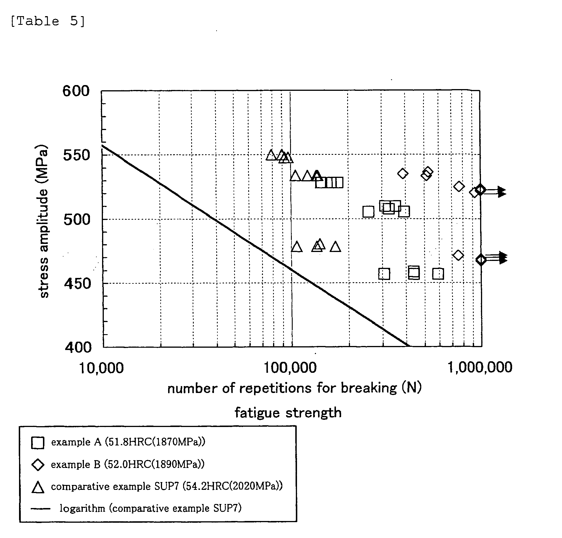
- According to Table 5, in comparison of the fatigue strength of 49HRC and 54HRC in the comparative example SUP7, it is apparent that the fatigue life of 54HRC having a higher hardness is longer than the life of 49HRC at all stress amplitudes. Although the hardnesses of the example A and example B are HRC52 and lower than HRC54 of the comparative example SUP7, the examples A, B have long lives than 54HRC of the comparison SUP7 at all stress amplitudes. Further, it is apparent that the examples A, B indicate a fatigue strength of more than 200, 000 times under a condition in which the maximum shearing stress is 1176MPa (average stress 735MPa + stress amplitude 441MPa) thereby indicating that they are springs which achieve reduction of the weight. Further, in comparison between the examples, the example B having more additive element indicates a longer life than the example A.
- Evaluation of the permanent setting property was carried out by tightening test.
- The tightening test is carried out in a following procedure. (a) A load P1 is applied to the coil spring with a load testing machine so as to generate a predetermined shearing stress, for example, 1176MPa so that the spring is allowed to deflect up to a corresponding height H. With this condition, the height of the spring is constrained with a jig. (b) The spring is heated at a predetermined temperature in a predetermined interval of time , at 80°C for 96 hours in this test, so as to generate creep deformation in the spring. (c) After the creep deformation is generated, the spring is released from the jig after the test time elapses and the spring is allowed to deflect up to the height H and then, a load P2 at that time is read. (d) A residual shearing distortion y is calculated according to a following equation (1) with a difference ΔP between an initial applied load and a load after the test ends. Where D is a coil average diameter, d is wire diameter and G is shear modules.

- Table 6 shows a comparison of the permanent setting property in the tightening test between the examples and the comparative examples.


- According to Table 6, the example A having hardness of 52HRC indicates an far more better permanent setting property than the comparative example (SUP7) having lower hardness of 49 HRC. Further, it indicates a substantially equal permanent setting property under all tightening stresses as compared with the SUP7 having hardness of 54HRC, that is higher than the example A. Further, the example B having hardness of 52HRC indicates an excellent permanent setting property as compared to the SUP7 of the 54HRC having higher hardness.
- The corrosion fatigue test was carried out in a following procedure. (a) Salt water of 5% NaCl at 35°C is sprayed to a coil spring for use in a test for 0.5 hours. (b) The spring is vibrated 3,000 times at a predetermined test stress, for example, with 735±490MPa at a room temperature in a wet condition, for 30 minutes. (c) After the vibration, the spring is left in a constant temperature and constant humidity bath under wet atmosphere of 95% at 26°C for 23 hours. This procedure is repeated until the spring is broken. Table 7 shows results of the test.

- According to Table 7, the comparative example SUP7 has hardness of 51HRC and the vibration condition is 735±395MPa. The number of repetitions of endurance is 59,000 times. Contrary to this, in case of the example A, the number of repetitions of endurance is equal or higher than the comparative example, that is, 60,000 times although its hardness is 54HRC and test stress is 735±490MPa. Further, the example B indicated an excellent corrosion fatigue strength as the number of repetitions of endurance is 74, 000 times under the condition in which the hardness is 54HRC and the test condition is 735±490MPa.
Claims (6)
- A high strength spring steel containing in percent of mass: C: 0.36-0.48%; Si: 1.80-2.80%; Mn: 0.20-1.40%; P: 0.015% or less; S: 0.010% or less; Cu: 0.10-0.50%; Ni: 0.10-2.00%; Cr: 0.05-1.20%; s-Al: 0.005-0.040%; N: 0.002-0.012%; O: 0.002% or less, while the remainder is constituted of Fe and inevitable impurities, wherein following equations (1), (2), (3) are satisfied and the quantity of inclusions of 10µm or larger in diameter per field of vision of 100mm2 is 10 or less:


- A high strength spring steel containing in percent of mass: C: 0.36-0.48%; Si: 1.80-2.80%; Mn: 0.20-1.40%; P: 0.015% or less; S: 0.010% or less; Cu: 0.10-0.50%; Ni: 0.10-2.00%; Cr: 0.05-1.20%; s-Al: 0.005-0.040%; N: 0.002-0.012%; O: 0.002% or less, while further one or more of Ti: 0.020-0.070%, Nb: 0.020-0.050%, B: 0.0005-0.0030% are contained and the remainder is constituted of Fe and inevitable impurities, wherein following equations (1), (2)', (3) are satisfied and the quantity of inclusions of 10 µm or larger in diameter per field of vision of 100mm2 is 10 or less:


- The high strength spring steel according to claim 1 or 2 further containing one or two of Mo: 0.01-0.50% and V: 0.05-0.30% as steel component.
- A manufacturing method of high strength spring wherein the high strength spring steel according to claim 1-3, which is tempered to HRC52 or higher, is formed into a spring shape by hot forming or cold forming and warm shot peening is carried out so as to produce a high strength spring of 1176 MPa or higher in maximum shearing stress.
- The manufacturing method of high strength spring according to claim 4 wherein the warm shot peening is executed in a temperature range of 200-350°C.
- A high strength spring using the high strength spring steel according to claim 1-3 wherein the hardness is tempered to HRC52 or higher and the maximum shearing stress is 1176MPa or higher.
Applications Claiming Priority (1)
| Application Number | Priority Date | Filing Date | Title |
|---|---|---|---|
| PCT/JP2004/012277 WO2006022009A1 (en) | 2004-08-26 | 2004-08-26 | Steel for high strength spring, and high strength spring and method for manufacture thereof |
Publications (3)
| Publication Number | Publication Date |
|---|---|
| EP1801253A1 true EP1801253A1 (en) | 2007-06-27 |
| EP1801253A4 EP1801253A4 (en) | 2008-04-23 |
| EP1801253B1 EP1801253B1 (en) | 2014-11-05 |
Family
ID=35967232
Family Applications (1)
| Application Number | Title | Priority Date | Filing Date |
|---|---|---|---|
| EP04772233.5A Expired - Lifetime EP1801253B1 (en) | 2004-08-26 | 2004-08-26 | High strength spring and method for manufacture thereof |
Country Status (6)
| Country | Link |
|---|---|
| US (1) | US20070256765A1 (en) |
| EP (1) | EP1801253B1 (en) |
| JP (1) | JP4588030B2 (en) |
| CN (1) | CN101001969A (en) |
| ES (1) | ES2524326T3 (en) |
| WO (1) | WO2006022009A1 (en) |
Cited By (4)
| Publication number | Priority date | Publication date | Assignee | Title |
|---|---|---|---|---|
| EP2322819A1 (en) * | 2009-11-12 | 2011-05-18 | Benteler Stahl/Rohr Gmbh | Spring element and method for manufacturing a spring element |
| EP2639328A4 (en) * | 2010-11-11 | 2017-03-29 | NHK Spring Co., Ltd. | High-strength spring steel, method for producing high-strength spring, and high-strength spring |
| EP3409810A4 (en) * | 2016-01-26 | 2019-07-31 | Nippon Steel Corporation | SPRING STEEL |
| US10689726B2 (en) | 2014-09-04 | 2020-06-23 | ThyssenKrupp Federn und Stabilisatoren GmbH | Method for producing hot-formed steel springs |
Families Citing this family (30)
| Publication number | Priority date | Publication date | Assignee | Title |
|---|---|---|---|---|
| CN102268604A (en) * | 2007-07-20 | 2011-12-07 | 株式会社神户制钢所 | Steel wire material for spring and its producing method |
| JP5653020B2 (en) | 2009-09-29 | 2015-01-14 | 中央発條株式会社 | Spring steel and springs with excellent corrosion fatigue strength |
| JP5653022B2 (en) | 2009-09-29 | 2015-01-14 | 中央発條株式会社 | Spring steel and spring with excellent corrosion fatigue strength |
| JP5653021B2 (en) | 2009-09-29 | 2015-01-14 | 中央発條株式会社 | Spring steel and spring with excellent corrosion fatigue strength |
| JP5550359B2 (en) * | 2010-01-19 | 2014-07-16 | 中央発條株式会社 | Coil spring for automobile suspension |
| US8328169B2 (en) * | 2009-09-29 | 2012-12-11 | Chuo Hatsujo Kabushiki Kaisha | Spring steel and spring having superior corrosion fatigue strength |
| JP2011102617A (en) * | 2009-11-11 | 2011-05-26 | Nhk Spring Co Ltd | Pressure reducing valve apparatus |
| CN102162068B (en) * | 2010-02-21 | 2013-07-31 | 宝山钢铁股份有限公司 | Spring steel and manufacturing and thermal treatment method thereof |
| JP5711539B2 (en) * | 2011-01-06 | 2015-05-07 | 中央発條株式会社 | Spring with excellent corrosion fatigue strength |
| CN102443686A (en) * | 2012-01-09 | 2012-05-09 | 东风汽车悬架弹簧有限公司 | Surface shot blasting reinforcement method of steel plate spring |
| CN102991449B (en) * | 2012-11-08 | 2016-04-06 | 上海冠驰汽车安全技术有限公司 | A kind of force limit torsion rod of regarding Car safety strap |
| EP2990496B1 (en) | 2013-04-23 | 2018-10-31 | Nippon Steel & Sumitomo Metal Corporation | Spring steel having excellent fatigue characteristics and process for manufacturing same |
| CN105308201A (en) * | 2013-06-04 | 2016-02-03 | 中央发条株式会社 | Steel for springs, spring, and spring production method |
| CN103358234B (en) * | 2013-07-19 | 2015-09-30 | 山东海华汽车部件有限公司 | A kind of reed waste heat stress shot blasting technique |
| CN103667983B (en) * | 2013-11-08 | 2016-03-30 | 铜陵安东铸钢有限责任公司 | A kind of high-strength spring steel and preparation method thereof |
| JP6458927B2 (en) * | 2014-10-07 | 2019-01-30 | 大同特殊鋼株式会社 | High-strength spring steel with excellent wire rod rollability |
| EP3330400A1 (en) | 2015-07-28 | 2018-06-06 | Sidenor Investigación y Desarrollo, S.A. | Steel for springs of high resistance and hardenability |
| CN105258737B (en) * | 2015-11-23 | 2017-08-25 | 国家电网公司 | A Method for Predicting the Remaining Life of Corroded Towers of Power Transmission Lines in Industrial Areas |
| CN105385940B (en) * | 2015-12-15 | 2018-10-30 | 安徽楚江特钢有限公司 | A kind of spring steel alloy production technology |
| CN106011634A (en) * | 2016-07-26 | 2016-10-12 | 路望培 | Spring mechanical material and preparation method thereof |
| JP6356309B1 (en) | 2016-10-19 | 2018-07-11 | 三菱製鋼株式会社 | High-strength spring, method for manufacturing the same, steel for high-strength spring, and method for manufacturing the same |
| WO2018074003A1 (en) * | 2016-10-19 | 2018-04-26 | 三菱製鋼株式会社 | High-strength spring, method for producing same, steel for high-strength spring, and method for producing same |
| EP3814051B1 (en) * | 2018-06-29 | 2024-09-18 | AB Sandvik Coromant | Method of treating a cutting tool, and a cutting tool |
| CN109735771A (en) * | 2019-03-19 | 2019-05-10 | 马鞍山钢铁股份有限公司 | A kind of high-strength spring steel with excellent fatigue performance and corrosion resistance and its production method |
| JP7434748B2 (en) * | 2019-08-08 | 2024-02-21 | 大同特殊鋼株式会社 | spring steel |
| CN111321279A (en) * | 2020-02-25 | 2020-06-23 | 洛阳双瑞特种装备有限公司 | High-strength corrosion-resistant spring steel and heat treatment process thereof |
| CN111690882A (en) * | 2020-07-29 | 2020-09-22 | 攀钢集团研究院有限公司 | 660 MPa-grade high-corrosion-resistance weathering steel and preparation method thereof |
| CN114807555A (en) * | 2022-04-19 | 2022-07-29 | 安阳钢铁集团有限责任公司 | Production method of high-carbon high-silicon spring steel hot continuous rolling steel strip |
| CN114875326A (en) * | 2022-05-21 | 2022-08-09 | 湖南华菱湘潭钢铁有限公司 | Production method of flat spring steel |
| CN114875327A (en) * | 2022-05-25 | 2022-08-09 | 湖南华菱湘潭钢铁有限公司 | High-strength high-toughness spring flat steel and production method thereof |
Family Cites Families (9)
| Publication number | Priority date | Publication date | Assignee | Title |
|---|---|---|---|---|
| JP2842579B2 (en) * | 1991-10-02 | 1999-01-06 | 株式会社 神戸製鋼所 | High strength spring steel with excellent fatigue strength |
| JP3255296B2 (en) * | 1992-02-03 | 2002-02-12 | 大同特殊鋼株式会社 | High-strength steel for spring and method of manufacturing the same |
| US5776267A (en) * | 1995-10-27 | 1998-07-07 | Kabushiki Kaisha Kobe Seiko Sho | Spring steel with excellent resistance to hydrogen embrittlement and fatigue |
| JP3577411B2 (en) * | 1997-05-12 | 2004-10-13 | 新日本製鐵株式会社 | High toughness spring steel |
| DE19852734B4 (en) * | 1997-11-17 | 2005-02-24 | Chuo Hatsujo K.K., Nagoya | Spring with improved corrosion fatigue resistance |
| JPH11241143A (en) * | 1997-11-17 | 1999-09-07 | Chuo Spring Co Ltd | Spring with improved corrosion fatigue resistance |
| JP3246733B2 (en) * | 1999-10-29 | 2002-01-15 | 三菱製鋼室蘭特殊鋼株式会社 | High strength spring steel |
| JP3918587B2 (en) * | 2002-03-07 | 2007-05-23 | 大同特殊鋼株式会社 | Spring steel for cold forming |
| JP3896902B2 (en) * | 2002-06-06 | 2007-03-22 | 大同特殊鋼株式会社 | High-strength spring steel with excellent corrosion fatigue strength |
-
2004
- 2004-08-26 CN CNA2004800438097A patent/CN101001969A/en active Pending
- 2004-08-26 US US11/661,139 patent/US20070256765A1/en not_active Abandoned
- 2004-08-26 WO PCT/JP2004/012277 patent/WO2006022009A1/en not_active Ceased
- 2004-08-26 EP EP04772233.5A patent/EP1801253B1/en not_active Expired - Lifetime
- 2004-08-26 ES ES04772233.5T patent/ES2524326T3/en not_active Expired - Lifetime
- 2004-08-26 JP JP2006531172A patent/JP4588030B2/en not_active Expired - Lifetime
Cited By (5)
| Publication number | Priority date | Publication date | Assignee | Title |
|---|---|---|---|---|
| EP2322819A1 (en) * | 2009-11-12 | 2011-05-18 | Benteler Stahl/Rohr Gmbh | Spring element and method for manufacturing a spring element |
| EP2639328A4 (en) * | 2010-11-11 | 2017-03-29 | NHK Spring Co., Ltd. | High-strength spring steel, method for producing high-strength spring, and high-strength spring |
| US10689726B2 (en) | 2014-09-04 | 2020-06-23 | ThyssenKrupp Federn und Stabilisatoren GmbH | Method for producing hot-formed steel springs |
| EP3409810A4 (en) * | 2016-01-26 | 2019-07-31 | Nippon Steel Corporation | SPRING STEEL |
| US11390936B2 (en) | 2016-01-26 | 2022-07-19 | Nippon Steel Corporation | Spring steel |
Also Published As
| Publication number | Publication date |
|---|---|
| WO2006022009A1 (en) | 2006-03-02 |
| JP4588030B2 (en) | 2010-11-24 |
| EP1801253A4 (en) | 2008-04-23 |
| EP1801253B1 (en) | 2014-11-05 |
| JPWO2006022009A1 (en) | 2008-05-08 |
| CN101001969A (en) | 2007-07-18 |
| US20070256765A1 (en) | 2007-11-08 |
| ES2524326T3 (en) | 2014-12-05 |
Similar Documents
| Publication | Publication Date | Title |
|---|---|---|
| EP1801253B1 (en) | High strength spring and method for manufacture thereof | |
| EP2397571A1 (en) | Steel for high-strength vehicle stabilizer with excellent corrosion resistance and low-temperature toughness, and process for the production of same, and stabilizer | |
| EP2058414B1 (en) | High-strength spring steel wire, high-strength springs and processes for production of both | |
| EP2518175B1 (en) | High-strength spring steel | |
| JP5177323B2 (en) | High-strength steel material and high-strength bolt excellent in delayed fracture resistance | |
| JP5135557B2 (en) | High-strength steel material and high-strength bolt excellent in delayed fracture resistance | |
| US5286312A (en) | High-strength spring steel | |
| EP2708612A1 (en) | Steel for automotive suspension spring component, automotive suspension spring component, and manufacturing method for same | |
| CN1318628C (en) | Spring steel with improved hardenability and pitting resistance | |
| EP2514846B1 (en) | Steel for leaf spring with high fatigue strength, and leaf spring component | |
| US8328169B2 (en) | Spring steel and spring having superior corrosion fatigue strength | |
| KR20050105281A (en) | Steel wire for high strength spring excellent in workability and high strength spring | |
| EP3124638B1 (en) | Stabilizer steel having high strength and excellent corrosion resistance, vehicle stabilizer employing same, and method for manufacturing same | |
| EP2816130B1 (en) | Spring steel | |
| JP4283643B2 (en) | Bearing steel and bearing parts with excellent corrosion resistance | |
| JP2003105496A (en) | Spring steel with excellent low decarburization and delayed fracture resistance | |
| JP3896902B2 (en) | High-strength spring steel with excellent corrosion fatigue strength | |
| EP1801255A1 (en) | Cold formable spring steel wire excellent in cold cutting capability and fatigue properties and manufacturing process thereof | |
| JP5214292B2 (en) | Spring steel with excellent hydrogen embrittlement resistance and corrosion fatigue strength, and high-strength spring parts using the same | |
| JP2002097543A (en) | Steel superior in toughness | |
| JP2016084515A (en) | Spring steel and spring | |
| JP4261760B2 (en) | High strength spring steel excellent in hydrogen fatigue fracture resistance and manufacturing method thereof | |
| EP3336214B1 (en) | High-strength spring, method for producing same, steel for high-strength spring, and method for producing same | |
| JP2021025111A (en) | Spring steel | |
| JP2007031747A (en) | Steel wire rod for spring and method for judging fatigue resistance thereof |
Legal Events
| Date | Code | Title | Description |
|---|---|---|---|
| PUAI | Public reference made under article 153(3) epc to a published international application that has entered the european phase |
Free format text: ORIGINAL CODE: 0009012 |
|
| 17P | Request for examination filed |
Effective date: 20070307 |
|
| AK | Designated contracting states |
Kind code of ref document: A1 Designated state(s): DE ES FR GB |
|
| RBV | Designated contracting states (corrected) |
Designated state(s): DE ES FR GB |
|
| DAX | Request for extension of the european patent (deleted) | ||
| A4 | Supplementary search report drawn up and despatched |
Effective date: 20080320 |
|
| 17Q | First examination report despatched |
Effective date: 20110922 |
|
| GRAP | Despatch of communication of intention to grant a patent |
Free format text: ORIGINAL CODE: EPIDOSNIGR1 |
|
| INTG | Intention to grant announced |
Effective date: 20140522 |
|
| GRAS | Grant fee paid |
Free format text: ORIGINAL CODE: EPIDOSNIGR3 |
|
| GRAA | (expected) grant |
Free format text: ORIGINAL CODE: 0009210 |
|
| AK | Designated contracting states |
Kind code of ref document: B1 Designated state(s): DE ES FR GB |
|
| REG | Reference to a national code |
Ref country code: GB Ref legal event code: FG4D |
|
| REG | Reference to a national code |
Ref country code: DE Ref legal event code: R081 Ref document number: 602004046096 Country of ref document: DE Owner name: DAIDO TOKUSHUKO K.K., NAGOYA-SHI, JP Free format text: FORMER OWNERS: DAIDO TOKUSHUKO K.K., NAGOYA, AICHI, JP; NHK SPRING LTD., YOKOHAMA, KANAGAWA, JP Ref country code: DE Ref legal event code: R081 Ref document number: 602004046096 Country of ref document: DE Owner name: NHK SPRING CO., LTD., YOKOHAMA-SHI, JP Free format text: FORMER OWNERS: DAIDO TOKUSHUKO K.K., NAGOYA, AICHI, JP; NHK SPRING LTD., YOKOHAMA, KANAGAWA, JP |
|
| REG | Reference to a national code |
Ref country code: ES Ref legal event code: FG2A Ref document number: 2524326 Country of ref document: ES Kind code of ref document: T3 Effective date: 20141205 |
|
| REG | Reference to a national code |
Ref country code: DE Ref legal event code: R096 Ref document number: 602004046096 Country of ref document: DE Effective date: 20141218 |
|
| REG | Reference to a national code |
Ref country code: DE Ref legal event code: R097 Ref document number: 602004046096 Country of ref document: DE |
|
| PLBE | No opposition filed within time limit |
Free format text: ORIGINAL CODE: 0009261 |
|
| STAA | Information on the status of an ep patent application or granted ep patent |
Free format text: STATUS: NO OPPOSITION FILED WITHIN TIME LIMIT |
|
| 26N | No opposition filed |
Effective date: 20150806 |
|
| REG | Reference to a national code |
Ref country code: FR Ref legal event code: PLFP Year of fee payment: 13 |
|
| REG | Reference to a national code |
Ref country code: FR Ref legal event code: PLFP Year of fee payment: 14 |
|
| REG | Reference to a national code |
Ref country code: FR Ref legal event code: PLFP Year of fee payment: 15 |
|
| P01 | Opt-out of the competence of the unified patent court (upc) registered |
Effective date: 20230515 |
|
| PGFP | Annual fee paid to national office [announced via postgrant information from national office to epo] |
Ref country code: GB Payment date: 20230706 Year of fee payment: 20 Ref country code: ES Payment date: 20230901 Year of fee payment: 20 |
|
| PGFP | Annual fee paid to national office [announced via postgrant information from national office to epo] |
Ref country code: FR Payment date: 20230703 Year of fee payment: 20 Ref country code: DE Payment date: 20230703 Year of fee payment: 20 |
|
| REG | Reference to a national code |
Ref country code: DE Ref legal event code: R071 Ref document number: 602004046096 Country of ref document: DE |
|
| REG | Reference to a national code |
Ref country code: ES Ref legal event code: FD2A Effective date: 20240902 |
|
| REG | Reference to a national code |
Ref country code: GB Ref legal event code: PE20 Expiry date: 20240825 |
|
| PG25 | Lapsed in a contracting state [announced via postgrant information from national office to epo] |
Ref country code: GB Free format text: LAPSE BECAUSE OF EXPIRATION OF PROTECTION Effective date: 20240825 |
|
| PG25 | Lapsed in a contracting state [announced via postgrant information from national office to epo] |
Ref country code: ES Free format text: LAPSE BECAUSE OF EXPIRATION OF PROTECTION Effective date: 20240827 |
|
| PG25 | Lapsed in a contracting state [announced via postgrant information from national office to epo] |
Ref country code: GB Free format text: LAPSE BECAUSE OF EXPIRATION OF PROTECTION Effective date: 20240825 Ref country code: ES Free format text: LAPSE BECAUSE OF EXPIRATION OF PROTECTION Effective date: 20240827 |