EP1801048B1 - Vorrichtung zur Produktbehandlung - Google Patents
Vorrichtung zur Produktbehandlung Download PDFInfo
- Publication number
- EP1801048B1 EP1801048B1 EP06126467A EP06126467A EP1801048B1 EP 1801048 B1 EP1801048 B1 EP 1801048B1 EP 06126467 A EP06126467 A EP 06126467A EP 06126467 A EP06126467 A EP 06126467A EP 1801048 B1 EP1801048 B1 EP 1801048B1
- Authority
- EP
- European Patent Office
- Prior art keywords
- arm
- axis
- top half
- cross member
- fitted
- Prior art date
- Legal status (The legal status is an assumption and is not a legal conclusion. Google has not performed a legal analysis and makes no representation as to the accuracy of the status listed.)
- Active
Links
Images

Classifications
-
- B—PERFORMING OPERATIONS; TRANSPORTING
- B65—CONVEYING; PACKING; STORING; HANDLING THIN OR FILAMENTARY MATERIAL
- B65G—TRANSPORT OR STORAGE DEVICES, e.g. CONVEYORS FOR LOADING OR TIPPING, SHOP CONVEYOR SYSTEMS OR PNEUMATIC TUBE CONVEYORS
- B65G47/00—Article or material-handling devices associated with conveyors; Methods employing such devices
- B65G47/74—Feeding, transfer, or discharging devices of particular kinds or types
- B65G47/90—Devices for picking-up and depositing articles or materials
- B65G47/904—Devices for picking-up and depositing articles or materials provided with rotary movements only
-
- B—PERFORMING OPERATIONS; TRANSPORTING
- B65—CONVEYING; PACKING; STORING; HANDLING THIN OR FILAMENTARY MATERIAL
- B65G—TRANSPORT OR STORAGE DEVICES, e.g. CONVEYORS FOR LOADING OR TIPPING, SHOP CONVEYOR SYSTEMS OR PNEUMATIC TUBE CONVEYORS
- B65G47/00—Article or material-handling devices associated with conveyors; Methods employing such devices
- B65G47/74—Feeding, transfer, or discharging devices of particular kinds or types
- B65G47/90—Devices for picking-up and depositing articles or materials
- B65G47/91—Devices for picking-up and depositing articles or materials incorporating pneumatic, e.g. suction, grippers
- B65G47/915—Devices for picking-up and depositing articles or materials incorporating pneumatic, e.g. suction, grippers provided with drive systems with rotary movements only
-
- B—PERFORMING OPERATIONS; TRANSPORTING
- B65—CONVEYING; PACKING; STORING; HANDLING THIN OR FILAMENTARY MATERIAL
- B65G—TRANSPORT OR STORAGE DEVICES, e.g. CONVEYORS FOR LOADING OR TIPPING, SHOP CONVEYOR SYSTEMS OR PNEUMATIC TUBE CONVEYORS
- B65G59/00—De-stacking of articles
- B65G59/02—De-stacking from the top of the stack
-
- B—PERFORMING OPERATIONS; TRANSPORTING
- B65—CONVEYING; PACKING; STORING; HANDLING THIN OR FILAMENTARY MATERIAL
- B65G—TRANSPORT OR STORAGE DEVICES, e.g. CONVEYORS FOR LOADING OR TIPPING, SHOP CONVEYOR SYSTEMS OR PNEUMATIC TUBE CONVEYORS
- B65G61/00—Use of pick-up or transfer devices or of manipulators for stacking or de-stacking articles not otherwise provided for
Definitions
- the present invention relates to a product handling device.
- the present invention relates to a device for handling glass bottles and similar, to which the following description refers purely by way of example.
- depalletizing machines are known in which the support trays, on top of the "pallet" of bottles being unloaded inside the depalletizing machine, are removed by an articulated pantograph arm fitted on the end with a pneumatic gripping member.
- the articulated pantograph arm is fixed to and projects from a horizontal support cross member movable vertically on the supporting frame of the machine, and comprises a first half-arm fitted to the body of the support cross member to rotate, with respect to the body of the support cross member, about a first vertical axis; a second half-arm fitted to the free end of the first half-arm to rotate freely, with respect to the first half-arm, about a second vertical axis; and cascade gearing for transmitting rotation of the first half-arm about the first vertical axis to the body of the second half-arm, so as to coordinate the scissor-like opening of the two half-arms with rotation of the first half-arm with respect to the horizontal support cross member.
- the first half-arm of the articulated pantograph arm is hinged to the horizontal support cross member by a through pin, which extends coaxially with the first vertical axis and engages the body of the cross member in freely rotating manner.
- a first end of the pin is fitted rigidly to the body of the first half-arm, and the second end of the pin is connected mechanically to an actuating member which, on command, rotates the pin about the first vertical axis to open the two half-arms scisor-fashion.
- articulated pantograph arms have so far been used exclusively for handling fairly lightweight products, such as the support trays used in the construction of "pallets" of glass bottles, because the torque exerted on the pin to scissor-open the two half-arms increases considerably alongside an increase in the weight of the products being handled, with all the drawbacks this entails.
- a high torque in fact, calls for the use of actuating members of greater power, weight, and running cost than those of other solutions currently used for the purpose, thus making articulated pantograph arms economically unfeasible for handling products even only slightly heavier than normal support trays.
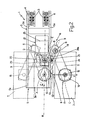
- Number 1 in Figures 1 and 2 indicates as a whole a device for moving products in two substantially perpendicular directions, and which may be used to particular advantage for handling glass bottles 2 or similar.
- Device 1 comprises an on-floor supporting structure having a straight supporting guide 3 extending substantially vertically alongside the bottle 2 handling area; a support carriage 4 mounted to run along straight guide 3; known drive means (not shown) for moving carriage 4, on command, along straight guide 3; and a support cross member 5 projecting substantially horizontally from carriage 4 over the bottle 2 handling area, so as to move vertically over the bottle 2 handling area while remaining parallel to itself at all times.
- Device 1 also comprises an articulated pantograph arm 6 fixed beneath support cross member 5 to open or part scissor-fashion in a substantially horizontal plane (parallel to the Figure 2 plane) extending just above the bottle 2 handling area; and a movable gripping member 7, which is fixed to the free end of articulated arm 6 to face the bottle 2 handling area below, and is designed to selectively grip and retain an orderly, compact group of bottles 2.
- Movable gripping member 7 being a commonly known device within the industry, needs no further description, and may obviously be replaced with another type of movable gripping member designed to grip and retain other types of products.
- support cross member 5 is defined by a straight U-section beam 5 with the two sides 5a positioned vertically, and with the central portion 5b positioned substantially horizontally and directly facing the bottle 2 handling area, so as to act as a fastening point by which to fix articulated arm 6 to cross member 5.
- articulated pantograph arm 6 it comprises a top half-arm which is indicated in the following with number 8 and is fitted to the support cross member 5, or rather to central portion 5b of cross member 5, to rotate with respect to the cross member 5 about a substantially vertical axis A; and a bottom half-arm which is indicated in the following with number 9 and is fitted to the free end of half-arm 8 to rotate freely with respect to half-arm 8 about an axis B parallel to axis A.
- half-arms 8 and 9 extend horizontally one over the other, so that, at rest, they are substantially coplanar with a vertical reference plane R intersecting axis A; and first end of half-arm 8 is hinged to the support cross member 5 by a cylindrical through pin 10, which extends through flat portion 5b of cross member 5, coaxially with axis A, and engages the body of half-arm 8 in freely rotating manner with the interposition of appropriate known rolling bearings.
- the first end of half-arm 8 is mounted for rotation on through pin 10, which projects from flat portion 5b of cross member 5, coaxially with axis A, and is connected rigidly to flat portion 5b.
- a first end of half-arm 9 is hinged to second end of half-arm 8 by a cylindrical through pin 11 extending, coaxially with axis B, through the bodies of half-arms 8 and 9. More specifically, pin 11 of half-arm 9 is fitted rigidly to the end of half-arm 9, and is fitted in rotary manner to the body of half-arm 8 with the interposition of appropriate known rolling bearings.
- articulated pantograph arm 6 also comprises cascade gearing 12 for transmitting rotation of half-arm 8 about axis A to the body of half-arm 9, so that the body of half-arm 9 rotates, with respect to half-arm 8 and about axis B, at twice the angular speed of, and in the opposite direction to, rotation of half-arm 8 about axis A.
- cascade gearing 12 transmits rotation of half-arm 8 about axis A to the body of half-arm 9, so as to coordinate scissor opening of half-arms 8 and 9 with rotation of half-arm 8 about axis A.
- the cascade gearing 12 for synchronizing the movement of half-arm 9 about axis B with the movement of half-arm 8 about axis A comprises a main gear 13 fitted rigidly to pin 10 of half-arm 8 and therefore also integral with flat portion 5b of cross member 5; a secondary gear 14 fitted rigidly to the top end of pin 11 of half-arm 9; and a drive chain 15 looped about gears 13 and 14.
- the nominal diameter of gear 13 is twice that of gear 14, so that gear 14 rotates about axis B at twice the angular speed at which half-arm 8 rotates about gear 13.
- articulated pantograph arm 6 comprises a cylindrical fastening pin 16, which is fitted through the free end of half-arm 9, projects from the free end of half-arm 9, coaxially with an axis C parallel to axes A and B, and has a coupling flange or similar at the bottom, to which movable gripping member 7 is fixed; and a second cascade gearing 17 for transmitting rotation of half-arm 9, with respect to half-arm 8 and about axis B, to pin 16.
- fastening pin 16 is inserted in freely rotating manner inside the body of half-arm 9, at a distance l 2 from axis B equal to the distance l 1 between axes A and B.
- the distance l 1 between axes A and B equals the distance l 2 between axes B and C.
- cascade gearing 17 it transmits rotation of half-arm 9, with respect to half-arm 8 and about axis B, to fastening pin 16 with a predetermined gear ratio, so that pin 16 rotates about axis C inside half-arm 9 in the opposite direction to, and at half the angular speed of, rotation of pin 11 about axis B inside half-arm 8.
- cascade gearing 17 As half-arms 8 and 9 are parted, i.e. as articulated arm 6 is extended, cascade gearing 17 therefore rotates pin 16 about axis C inside half-arm 9 in phase opposition to half-arm 9, so as to compensate rotation of half-arm 9 about axis B. More specifically, cascade gearing 17 rotates fastening pin 16 with respect to half-arm 9 - itself possessed of rotary-translation motion - so that, to an observer, pin 16, and movable gripping member 7 integral with it, move in a straight line at all times in direction d, with no rotation about axis C.
- cascade gearing 17 rotates pin 16 inside half-arm 9 so that, as articulated arm 6 extends, movable gripping member 7 is maintained perfectly parallel to itself at all times.
- cascade gearing 17 comprises a main gear 18 fitted in rotary manner to pin 11 of half-arm 8, between the body of half-arm 8 and the body of half-arm 9; a secondary gear 19 fitted rigidly to the top end of pin 16, at the opposite end to movable gripping member 7; and a drive chain 20 looped about gears 18 and 19.
- main gear 18 is fixed rigidly to the body of half-arm 8, and is half the nominal diameter of secondary gear 19, so that secondary gear 19 rotates about axis C at half the angular speed at which main gear 18 rotates with respect to half-arm 9.
- device 1 also comprises an actuating device 21, which, on command, rotates half-arm 8 about axis A to scissor open half-arms 8 and 9, and so move movable gripping member 7 selectively on one side or the other of vertical reference plane R.
- actuating device 21 which, on command, rotates half-arm 8 about axis A to scissor open half-arms 8 and 9, and so move movable gripping member 7 selectively on one side or the other of vertical reference plane R.
- actuating device 21 comprises a drive shaft 22, which extends alongside and parallel to pin 10 of half-arm 8, and is fitted through the body of support cross member 5 - or, rather, flat portion 5b of cross member 5 - so as to project partly beneath cross member 5, with its bottom end facing half-arm 8.
- shaft 22 extends coaxially with an axis D parallel to and a distance from axis A, and which preferably, though not necessarily, lies in vertical reference plane R.
- actuating device 21 also comprises a crank 23, which projects from the bottom end of shaft 22 in a direction substantially perpendicular to axis D, and is fitted rigidly to shaft 22 to rotate, integrally with shaft 22, about axis D; and a cam follower pin 24, which projects from the distal end of crank 23, coaxially with an axis E parallel to and a distance from axis D, so as to slide inside a longitudinal groove 24a formed in the body of half-arm 8.
- Actuating device 21 also comprises a drive unit 25 connected mechanically to the drive shaft 22 to rotate drive shaft 22, on command, clockwise or anticlockwise about axis D, and so rotate crank 23 about axis D and half-arm 8 about axis A.
- Drive unit 25 is obviously fixed to the support cross member 5, and, in the example shown, is defined by a known electric motor reducer 25, which is fixed to and projects from cross member 5 so that its output shaft extends coaxially with axis D, and projects beneath support cross member 5, through a through opening formed in flat portion 5b of cross member 5, to define drive shaft 22 of actuating device 21.
- crank 23 moves cam follower pin 24 along a semicircular path, centred about axis D, on one side or the other of vertical reference plane R.
- cam follower pin 24 slides freely inside longitudinal groove 24a formed in half-arm 8, and exerts torque on half-arm 8 to rotate it about axis A and so scissor open articulated arm 6.
- the maximum angle of rotation ⁇ of half-arm 8 about axis A depends on the distance between axes D and E, and on the length and position of longitudinal groove 24a on half-arm 8.
- Another advantage of device 1 is that of subjecting the products being handled to less acceleration, as compared with the solution described in European Patent EP-1338536 , along the start and end portion of the path travelled by movable gripping member 7.
Landscapes
- Engineering & Computer Science (AREA)
- Mechanical Engineering (AREA)
- Manipulator (AREA)
- Control And Other Processes For Unpacking Of Materials (AREA)
- Treatment Of Fiber Materials (AREA)
- Soil Working Implements (AREA)
- Specific Conveyance Elements (AREA)
Claims (5)
- Einrichtung (1) zum Handhaben von Produkten (2), welche ein Lagerquerträgerteil (5) aufweist, welches sich im Wesentlichen horizontal über einen Produkthandhabungsbereich erstreckt; einen Gelenk-Pantograph-Arm (6), der am Lagerquerträgerteil (5) angebracht ist, um scherenartig sich in einer im Wesentlichen horizontalen Ebene zu öffnen, welche sich über den Produkthandhabungsbereich erstreckt; und ein bewegbares Greifteil (7), welches am freien Ende des Gelenkarms (6) angebracht ist, derart, dass es dem darunter liegenden Produkthandhabungsbereich zugewandt ist und ausgebildet ist, um selektiv zumindest ein bestimmtes Produkt (2) zu greifen und zu halten;
wobei der Gelenk-Pantograph-Arm (6) einen Kopf-Ha1b-Arm (8) aufweist, der am Lagerquerträgerteil (5) angebracht ist, um in Bezug auf das Lagerquerträgerteil um eine im Wesentlichen vertikale erste Achse (A) zu drehen; einen Boden-Halb-Arm (9), der am Kopf-Halb-Arm (8) angebracht ist, um in Bezug auf den Kopf-Halb-Arm um eine zweite Achse (B) parallel zur ersten Achse (A) frei zu drehen; und ein erstes Kaskadengetriebe (12) zur Übertragung der Drehung des Kopf-Halb-Arms (8) um die erste Achse (A) auf den Bodea-Halb-Arm (9), so dass der Boden-Halb-Arm (9) in Bezug auf den Kopf-Halb-Arm (8) und um die zweite Achse (B) mit der zweifachen Winkelgeschwindigkeit von und in der entgegengesetzten Richtung zu der Drehung des Kopf-Halb-Arms (8) um die erste Achse (A) dreht, so dass das Öffnen des Kopf-Halb-Arms (8) und des Boden-Halb-Arms (9) sich koordinatenartig schneiden;
wobei die Einrichtung (1) außerdem eine Betätigungseinrichtung (21) aufweist, welche auf Befehl den Kopf-Ha1b-Arm (8) um die erste Achse (A) dreht, um den Gelenk-Pantograph-Arm (6) scherenartig zu öffnen und um das bewegbare Greifteil (7) zu bewegen;
und dadurch gekennzeichnet ist, dass die Betätigungseinrichtung (21) aufweist:eine Antriebswelle (22), welche sich koaxial mit einer dritten Achse (D) parallel zu und in einem Abstand von der ersten Achse (A) erstreckt und in drehbarer Weise am Lagerquerträgerteil (5) befestigt ist, wobei ein axiales Ende der Antriebswelle dem Kopf-Halb-Arm (8) zugewandt ist;eine Kurbel (23), welche starr am axialen Ende der Antriebswelle (22) befestigt ist und die sich von der Antriebswelle (22) in einer Richtung im Wesentlichen senkrecht zur dritten Achse (D) ragt;einen Nockenfolgerstift (24), der von dem distalen Ende der Kurbel (23) ragt, koaxial mit einer vierten Achse (E) parallel zu und einem Abstand von der dritten Achse (D), um so innerhalb einer Längsnut (24a) zu gleiten, welche im Körper des Kopf-Halb-Arms (8) gebildet ist; undeine Antriebseinheit (25), welche mechanisch mit der Antriebswelle (22) verbunden ist und diese auf Befehl im Uhrzeigersinn oder gegen den Uhrzeigersinn um die dritte Achse (D) dreht, um somit die Kurbel (23) um die dritte Achse (D) zu drehen. - Einrichtung nach Anspruch 1, dadurch gekennzeichnet, dass das erste Ende des Kopf-Halb-Arms (8) an das Lagerquerträgerteil (5) über einen ersten Durchgangsstift (10) drehbar angelenkt ist, der sich koaxial mit der ersten Achse (A) erstreckt und den Körper des Kopf-Halb-Arms (8) in einer freien drehbaren Weise erfasst; und dass ein erstes Ende des Boden-Halb-Arms (9) an das zweite Ende des Kopf-Halb-Arms (8) über einen zweiten Durchgangsstift (11) drehbar angelenkt ist, der sich koaxial zu der zweiten Achse (B) erstreckt, starr am Boden-Halb-Arm (9) befestigt ist und in drehbarer Weise am Kopf-Halb-Arm (8) befestigt ist.
- Einrichtung nach einem der vorhergehenden Ansprüche, dadurch gekennzeichnet, dass der Gelenk-Pantograph-Arm (6) außerdem einen Befestigungsstift (16) aufweist, der durch das freie Ende des Boden-Halb-Arms (9) eingepasst ist, vom freien Ende des Boden-Halb-Arms (9) koaxial mit einer fünften Achse (C) parallel zur ersten Achse (A) ragt und ausgebildet ist, das bewegbare Greifteil (7) zu lagern; wobei der Abstand (l2) zwischen der fünften Achse (C) und der zweiten Achse (B) gleich dem Abstand (l1) zwischen der ersten Achse (A) und der zweiten Achse (B) ist.
- Einrichtung nach Anspruch 2, dadurch gekennzeichnet, das5 der Gelenk-Pantograph-Arm (6) außerdem ein zweites Kaskadengetriebe (17) aufweist, um die Drehbewegung des Boden-Halb-Arms (9) in Bezug auf den Kopf-Halb-Arm (8) und um die zweite Achse (B) auf dem Befestigungsstift (16) zu übertragen, so dass der Befestigungsstift (16) rund um die fünfte Achse (C) und in Bezug auf den Boden-Halb-Arm (9) in der entgegengesetzten Richtung zu und mit der Hälfte der Winkelgeschwindigkeit der Drehung des Boden-Halb-Arms (9) um die zweite Achse (B) und in Bezug auf den Kopf-Halb-Arm (8) dreht.
- Einrichtung nach einem der vorhergehenden Ansprüche, dadurch gekennzeichnet, dass diese eine Flur-Lager-Strnktur aufweist, welche eine gerade Lagerführung (3) aufweist, welche sich im Wesentlichen vertikal längsseitig zum Produkthandhabungsbereich erstreckt; einen Lagerwagen (4), der befestigt ist, um längs der geraden Führung (3) zu laufen; und eine Antriebseinrichtung zum Bewegen des Lagerwagens (4) auf Befehl längs der geraden Führung (3); wobei das Lagerquerträgerteil (5) an dem Lagerwagen (4) über den Produkthandhabungsbereich befestigt ist und davon ragt.
Applications Claiming Priority (1)
| Application Number | Priority Date | Filing Date | Title |
|---|---|---|---|
| IT000882A ITTO20050882A1 (it) | 2005-12-20 | 2005-12-20 | Apparecchiatura per la movimentazione di prodotti |
Publications (2)
| Publication Number | Publication Date |
|---|---|
| EP1801048A1 EP1801048A1 (de) | 2007-06-27 |
| EP1801048B1 true EP1801048B1 (de) | 2008-08-13 |
Family
ID=37814159
Family Applications (1)
| Application Number | Title | Priority Date | Filing Date |
|---|---|---|---|
| EP06126467A Active EP1801048B1 (de) | 2005-12-20 | 2006-12-19 | Vorrichtung zur Produktbehandlung |
Country Status (5)
| Country | Link |
|---|---|
| EP (1) | EP1801048B1 (de) |
| AT (1) | ATE404476T1 (de) |
| DE (1) | DE602006002233D1 (de) |
| ES (1) | ES2309918T3 (de) |
| IT (1) | ITTO20050882A1 (de) |
Families Citing this family (7)
| Publication number | Priority date | Publication date | Assignee | Title |
|---|---|---|---|---|
| ITTV20060057A1 (it) * | 2006-04-04 | 2007-10-05 | Oma Srl | Apparecchiatura per la movimentazione di prodotti di tipo perfezionato. |
| CN104192564B (zh) * | 2014-09-01 | 2016-04-06 | 苏州博众精工科技有限公司 | 一种吸取机构 |
| CN106364905A (zh) * | 2016-08-29 | 2017-02-01 | 芜湖银星汽车零部件有限公司 | 一种卸料装置 |
| CN106276229A (zh) * | 2016-08-30 | 2017-01-04 | 成都市翻鑫家科技有限公司 | 一种产品移动取料机构 |
| CN107098170A (zh) * | 2017-05-23 | 2017-08-29 | 广东昂锐机械制造有限公司 | 码垛倍速机械臂 |
| CN110203691A (zh) * | 2019-05-07 | 2019-09-06 | 良忠城精密科技(苏州)有限公司 | 一种无级自动变间距模组 |
| CN119976378B (zh) * | 2025-04-14 | 2025-07-11 | 赣州万万年原生态饮品有限公司 | 一种基于码垛对齐辅助结构的桶装水码垛设备 |
Family Cites Families (3)
| Publication number | Priority date | Publication date | Assignee | Title |
|---|---|---|---|---|
| DE1061487B (de) * | 1957-02-01 | 1959-07-16 | Saint Gobain | Verfahren und Anordnung zum Durchschleusen von Koerpern, z. B. aus Glas oder Keramikdurch einen Waermeofen |
| DE3511531A1 (de) * | 1985-03-29 | 1986-10-09 | Audi AG, 8070 Ingolstadt | Vorrichtung zum umsetzen von gegenstaenden |
| ITTO20020157A1 (it) * | 2002-02-25 | 2003-08-25 | Oma Srl | Macchina depallettizzatrice. |
-
2005
- 2005-12-20 IT IT000882A patent/ITTO20050882A1/it unknown
-
2006
- 2006-12-19 AT AT06126467T patent/ATE404476T1/de not_active IP Right Cessation
- 2006-12-19 EP EP06126467A patent/EP1801048B1/de active Active
- 2006-12-19 DE DE602006002233T patent/DE602006002233D1/de active Active
- 2006-12-19 ES ES06126467T patent/ES2309918T3/es active Active
Also Published As
| Publication number | Publication date |
|---|---|
| ATE404476T1 (de) | 2008-08-15 |
| ES2309918T3 (es) | 2008-12-16 |
| ITTO20050882A1 (it) | 2007-06-21 |
| DE602006002233D1 (de) | 2008-09-25 |
| EP1801048A1 (de) | 2007-06-27 |
Similar Documents
| Publication | Publication Date | Title |
|---|---|---|
| EP1842809A1 (de) | Erweiterte Produkthandhabungsvorrichtung | |
| US8631926B2 (en) | Device for pushing glass objects onto a conveyor belt | |
| US10843911B2 (en) | Lifting apparatus | |
| EP1801048B1 (de) | Vorrichtung zur Produktbehandlung | |
| CN108527420A (zh) | 一种多自由度、自定心抓取式机械手 | |
| ITBO940294A1 (it) | Unita' tappatrice per l'assemblaggio automatico di flaconi a pompa. | |
| CA1142192A (en) | Material handling device | |
| US4725191A (en) | Industrial robot assembly | |
| EP1338536B1 (de) | Vorrichtung zum Entladen von Platten | |
| SE450471B (sv) | Hanteringsanordning for robot, serskilt for betjening av verktygsmaskiner | |
| CN103341669B (zh) | 插齿机双向让刀自动转换机构 | |
| EP2219801B1 (de) | Vorrichtung und verfahren zur bearbeitung von metallbehältern mit einer behältertransportvorrichtung | |
| EP0787667B1 (de) | Handhabungseinrichtung für Produkte | |
| CN113085253A (zh) | 一种抱盒移载组件、装置及包装盒生产设备 | |
| CN207375319U (zh) | 纸卷输送设备 | |
| CN114789903B (zh) | 一种智能机器人抓取搬运装置 | |
| CN201998175U (zh) | 平面多关节型机器人手臂组件 | |
| US10322829B2 (en) | Device, method and packaging machine for processing a packaging container | |
| CN223291210U (zh) | 一种双工位抓取同步翻转机构 | |
| CN208343555U (zh) | 钉箱机 | |
| US5588795A (en) | Handling apparatus | |
| US5481849A (en) | Operating unit for handling moving products | |
| RU2146213C1 (ru) | Устройство для послойной укладки штучных предметов | |
| US9539633B2 (en) | Machine tool drive system | |
| CN216804567U (zh) | 一种用于酒水外包装的装配系统 |
Legal Events
| Date | Code | Title | Description |
|---|---|---|---|
| PUAI | Public reference made under article 153(3) epc to a published international application that has entered the european phase |
Free format text: ORIGINAL CODE: 0009012 |
|
| AK | Designated contracting states |
Kind code of ref document: A1 Designated state(s): AT BE BG CH CY CZ DE DK EE ES FI FR GB GR HU IE IS IT LI LT LU LV MC NL PL PT RO SE SI SK TR |
|
| AX | Request for extension of the european patent |
Extension state: AL BA HR MK YU |
|
| 17P | Request for examination filed |
Effective date: 20071224 |
|
| GRAP | Despatch of communication of intention to grant a patent |
Free format text: ORIGINAL CODE: EPIDOSNIGR1 |
|
| AKX | Designation fees paid |
Designated state(s): AT BE BG CH CY CZ DE DK EE ES FI FR GB GR HU IE IS IT LI LT LU LV MC NL PL PT RO SE SI SK TR |
|
| GRAS | Grant fee paid |
Free format text: ORIGINAL CODE: EPIDOSNIGR3 |
|
| GRAA | (expected) grant |
Free format text: ORIGINAL CODE: 0009210 |
|
| AK | Designated contracting states |
Kind code of ref document: B1 Designated state(s): AT BE BG CH CY CZ DE DK EE ES FI FR GB GR HU IE IS IT LI LT LU LV MC NL PL PT RO SE SI SK TR |
|
| REG | Reference to a national code |
Ref country code: GB Ref legal event code: FG4D |
|
| REG | Reference to a national code |
Ref country code: CH Ref legal event code: EP |
|
| REG | Reference to a national code |
Ref country code: IE Ref legal event code: FG4D |
|
| REF | Corresponds to: |
Ref document number: 602006002233 Country of ref document: DE Date of ref document: 20080925 Kind code of ref document: P |
|
| REG | Reference to a national code |
Ref country code: GR Ref legal event code: EP Ref document number: 20080402841 Country of ref document: GR |
|
| REG | Reference to a national code |
Ref country code: ES Ref legal event code: FG2A Ref document number: 2309918 Country of ref document: ES Kind code of ref document: T3 |
|
| PG25 | Lapsed in a contracting state [announced via postgrant information from national office to epo] |
Ref country code: NL Free format text: LAPSE BECAUSE OF FAILURE TO SUBMIT A TRANSLATION OF THE DESCRIPTION OR TO PAY THE FEE WITHIN THE PRESCRIBED TIME-LIMIT Effective date: 20080813 Ref country code: LT Free format text: LAPSE BECAUSE OF FAILURE TO SUBMIT A TRANSLATION OF THE DESCRIPTION OR TO PAY THE FEE WITHIN THE PRESCRIBED TIME-LIMIT Effective date: 20080813 Ref country code: IS Free format text: LAPSE BECAUSE OF FAILURE TO SUBMIT A TRANSLATION OF THE DESCRIPTION OR TO PAY THE FEE WITHIN THE PRESCRIBED TIME-LIMIT Effective date: 20081213 |
|
| PG25 | Lapsed in a contracting state [announced via postgrant information from national office to epo] |
Ref country code: AT Free format text: LAPSE BECAUSE OF FAILURE TO SUBMIT A TRANSLATION OF THE DESCRIPTION OR TO PAY THE FEE WITHIN THE PRESCRIBED TIME-LIMIT Effective date: 20080813 Ref country code: LV Free format text: LAPSE BECAUSE OF FAILURE TO SUBMIT A TRANSLATION OF THE DESCRIPTION OR TO PAY THE FEE WITHIN THE PRESCRIBED TIME-LIMIT Effective date: 20080813 Ref country code: FI Free format text: LAPSE BECAUSE OF FAILURE TO SUBMIT A TRANSLATION OF THE DESCRIPTION OR TO PAY THE FEE WITHIN THE PRESCRIBED TIME-LIMIT Effective date: 20080813 Ref country code: SI Free format text: LAPSE BECAUSE OF FAILURE TO SUBMIT A TRANSLATION OF THE DESCRIPTION OR TO PAY THE FEE WITHIN THE PRESCRIBED TIME-LIMIT Effective date: 20080813 |
|
| PG25 | Lapsed in a contracting state [announced via postgrant information from national office to epo] |
Ref country code: BE Free format text: LAPSE BECAUSE OF FAILURE TO SUBMIT A TRANSLATION OF THE DESCRIPTION OR TO PAY THE FEE WITHIN THE PRESCRIBED TIME-LIMIT Effective date: 20080813 |
|
| PG25 | Lapsed in a contracting state [announced via postgrant information from national office to epo] |
Ref country code: BG Free format text: LAPSE BECAUSE OF FAILURE TO SUBMIT A TRANSLATION OF THE DESCRIPTION OR TO PAY THE FEE WITHIN THE PRESCRIBED TIME-LIMIT Effective date: 20081113 Ref country code: DK Free format text: LAPSE BECAUSE OF FAILURE TO SUBMIT A TRANSLATION OF THE DESCRIPTION OR TO PAY THE FEE WITHIN THE PRESCRIBED TIME-LIMIT Effective date: 20080813 |
|
| PG25 | Lapsed in a contracting state [announced via postgrant information from national office to epo] |
Ref country code: PT Free format text: LAPSE BECAUSE OF FAILURE TO SUBMIT A TRANSLATION OF THE DESCRIPTION OR TO PAY THE FEE WITHIN THE PRESCRIBED TIME-LIMIT Effective date: 20090113 Ref country code: CZ Free format text: LAPSE BECAUSE OF FAILURE TO SUBMIT A TRANSLATION OF THE DESCRIPTION OR TO PAY THE FEE WITHIN THE PRESCRIBED TIME-LIMIT Effective date: 20080813 Ref country code: SK Free format text: LAPSE BECAUSE OF FAILURE TO SUBMIT A TRANSLATION OF THE DESCRIPTION OR TO PAY THE FEE WITHIN THE PRESCRIBED TIME-LIMIT Effective date: 20080813 Ref country code: RO Free format text: LAPSE BECAUSE OF FAILURE TO SUBMIT A TRANSLATION OF THE DESCRIPTION OR TO PAY THE FEE WITHIN THE PRESCRIBED TIME-LIMIT Effective date: 20080813 |
|
| PLBE | No opposition filed within time limit |
Free format text: ORIGINAL CODE: 0009261 |
|
| STAA | Information on the status of an ep patent application or granted ep patent |
Free format text: STATUS: NO OPPOSITION FILED WITHIN TIME LIMIT |
|
| 26N | No opposition filed |
Effective date: 20090514 |
|
| PG25 | Lapsed in a contracting state [announced via postgrant information from national office to epo] |
Ref country code: EE Free format text: LAPSE BECAUSE OF FAILURE TO SUBMIT A TRANSLATION OF THE DESCRIPTION OR TO PAY THE FEE WITHIN THE PRESCRIBED TIME-LIMIT Effective date: 20080813 Ref country code: MC Free format text: LAPSE BECAUSE OF NON-PAYMENT OF DUE FEES Effective date: 20081231 |
|
| PG25 | Lapsed in a contracting state [announced via postgrant information from national office to epo] |
Ref country code: IT Free format text: LAPSE BECAUSE OF FAILURE TO SUBMIT A TRANSLATION OF THE DESCRIPTION OR TO PAY THE FEE WITHIN THE PRESCRIBED TIME-LIMIT Effective date: 20080813 |
|
| REG | Reference to a national code |
Ref country code: IE Ref legal event code: MM4A |
|
| PG25 | Lapsed in a contracting state [announced via postgrant information from national office to epo] |
Ref country code: IE Free format text: LAPSE BECAUSE OF NON-PAYMENT OF DUE FEES Effective date: 20081219 |
|
| PG25 | Lapsed in a contracting state [announced via postgrant information from national office to epo] |
Ref country code: SE Free format text: LAPSE BECAUSE OF FAILURE TO SUBMIT A TRANSLATION OF THE DESCRIPTION OR TO PAY THE FEE WITHIN THE PRESCRIBED TIME-LIMIT Effective date: 20081113 |
|
| PG25 | Lapsed in a contracting state [announced via postgrant information from national office to epo] |
Ref country code: PL Free format text: LAPSE BECAUSE OF FAILURE TO SUBMIT A TRANSLATION OF THE DESCRIPTION OR TO PAY THE FEE WITHIN THE PRESCRIBED TIME-LIMIT Effective date: 20080813 |
|
| PG25 | Lapsed in a contracting state [announced via postgrant information from national office to epo] |
Ref country code: HU Free format text: LAPSE BECAUSE OF FAILURE TO SUBMIT A TRANSLATION OF THE DESCRIPTION OR TO PAY THE FEE WITHIN THE PRESCRIBED TIME-LIMIT Effective date: 20090214 Ref country code: CY Free format text: LAPSE BECAUSE OF FAILURE TO SUBMIT A TRANSLATION OF THE DESCRIPTION OR TO PAY THE FEE WITHIN THE PRESCRIBED TIME-LIMIT Effective date: 20080813 Ref country code: LU Free format text: LAPSE BECAUSE OF NON-PAYMENT OF DUE FEES Effective date: 20081219 |
|
| PG25 | Lapsed in a contracting state [announced via postgrant information from national office to epo] |
Ref country code: TR Free format text: LAPSE BECAUSE OF FAILURE TO SUBMIT A TRANSLATION OF THE DESCRIPTION OR TO PAY THE FEE WITHIN THE PRESCRIBED TIME-LIMIT Effective date: 20080813 |
|
| REG | Reference to a national code |
Ref country code: CH Ref legal event code: PL |
|
| GBPC | Gb: european patent ceased through non-payment of renewal fee |
Effective date: 20101219 |
|
| PG25 | Lapsed in a contracting state [announced via postgrant information from national office to epo] |
Ref country code: CH Free format text: LAPSE BECAUSE OF NON-PAYMENT OF DUE FEES Effective date: 20101231 Ref country code: LI Free format text: LAPSE BECAUSE OF NON-PAYMENT OF DUE FEES Effective date: 20101231 |
|
| PG25 | Lapsed in a contracting state [announced via postgrant information from national office to epo] |
Ref country code: GB Free format text: LAPSE BECAUSE OF NON-PAYMENT OF DUE FEES Effective date: 20101219 |
|
| REG | Reference to a national code |
Ref country code: FR Ref legal event code: PLFP Year of fee payment: 10 |
|
| REG | Reference to a national code |
Ref country code: FR Ref legal event code: PLFP Year of fee payment: 11 |
|
| REG | Reference to a national code |
Ref country code: FR Ref legal event code: PLFP Year of fee payment: 12 |
|
| P01 | Opt-out of the competence of the unified patent court (upc) registered |
Effective date: 20230829 |
|
| PGFP | Annual fee paid to national office [announced via postgrant information from national office to epo] |
Ref country code: ES Payment date: 20250102 Year of fee payment: 19 |
|
| PGFP | Annual fee paid to national office [announced via postgrant information from national office to epo] |
Ref country code: DE Payment date: 20251126 Year of fee payment: 20 |
|
| PGFP | Annual fee paid to national office [announced via postgrant information from national office to epo] |
Ref country code: FR Payment date: 20251120 Year of fee payment: 20 |
|
| PGFP | Annual fee paid to national office [announced via postgrant information from national office to epo] |
Ref country code: GR Payment date: 20251121 Year of fee payment: 20 |