EP1801035B1 - Behälter für unterirdische Installation - Google Patents
Behälter für unterirdische Installation Download PDFInfo
- Publication number
- EP1801035B1 EP1801035B1 EP06126843A EP06126843A EP1801035B1 EP 1801035 B1 EP1801035 B1 EP 1801035B1 EP 06126843 A EP06126843 A EP 06126843A EP 06126843 A EP06126843 A EP 06126843A EP 1801035 B1 EP1801035 B1 EP 1801035B1
- Authority
- EP
- European Patent Office
- Prior art keywords
- container
- transport
- tube
- ascending tube
- ascending
- Prior art date
- Legal status (The legal status is an assumption and is not a legal conclusion. Google has not performed a legal analysis and makes no representation as to the accuracy of the status listed.)
- Active
Links
Images
Classifications
-
- B—PERFORMING OPERATIONS; TRANSPORTING
- B65—CONVEYING; PACKING; STORING; HANDLING THIN OR FILAMENTARY MATERIAL
- B65D—CONTAINERS FOR STORAGE OR TRANSPORT OF ARTICLES OR MATERIALS, e.g. BAGS, BARRELS, BOTTLES, BOXES, CANS, CARTONS, CRATES, DRUMS, JARS, TANKS, HOPPERS, FORWARDING CONTAINERS; ACCESSORIES, CLOSURES, OR FITTINGS THEREFOR; PACKAGING ELEMENTS; PACKAGES
- B65D90/00—Component parts, details or accessories for large containers
- B65D90/10—Manholes; Inspection openings; Covers therefor
- B65D90/105—Manholes; Inspection openings; Covers therefor for underground containers
-
- B—PERFORMING OPERATIONS; TRANSPORTING
- B65—CONVEYING; PACKING; STORING; HANDLING THIN OR FILAMENTARY MATERIAL
- B65D—CONTAINERS FOR STORAGE OR TRANSPORT OF ARTICLES OR MATERIALS, e.g. BAGS, BARRELS, BOTTLES, BOXES, CANS, CARTONS, CRATES, DRUMS, JARS, TANKS, HOPPERS, FORWARDING CONTAINERS; ACCESSORIES, CLOSURES, OR FITTINGS THEREFOR; PACKAGING ELEMENTS; PACKAGES
- B65D88/00—Large containers
- B65D88/005—Large containers of variable capacity, e.g. with movable or adjustable walls or wall parts, modular
-
- B—PERFORMING OPERATIONS; TRANSPORTING
- B65—CONVEYING; PACKING; STORING; HANDLING THIN OR FILAMENTARY MATERIAL
- B65D—CONTAINERS FOR STORAGE OR TRANSPORT OF ARTICLES OR MATERIALS, e.g. BAGS, BARRELS, BOTTLES, BOXES, CANS, CARTONS, CRATES, DRUMS, JARS, TANKS, HOPPERS, FORWARDING CONTAINERS; ACCESSORIES, CLOSURES, OR FITTINGS THEREFOR; PACKAGING ELEMENTS; PACKAGES
- B65D88/00—Large containers
- B65D88/02—Large containers rigid
- B65D88/022—Large containers rigid in multiple arrangement, e.g. stackable, nestable, connected or joined together side-by-side
-
- B—PERFORMING OPERATIONS; TRANSPORTING
- B65—CONVEYING; PACKING; STORING; HANDLING THIN OR FILAMENTARY MATERIAL
- B65D—CONTAINERS FOR STORAGE OR TRANSPORT OF ARTICLES OR MATERIALS, e.g. BAGS, BARRELS, BOTTLES, BOXES, CANS, CARTONS, CRATES, DRUMS, JARS, TANKS, HOPPERS, FORWARDING CONTAINERS; ACCESSORIES, CLOSURES, OR FITTINGS THEREFOR; PACKAGING ELEMENTS; PACKAGES
- B65D88/00—Large containers
- B65D88/02—Large containers rigid
- B65D88/06—Large containers rigid cylindrical
-
- B—PERFORMING OPERATIONS; TRANSPORTING
- B65—CONVEYING; PACKING; STORING; HANDLING THIN OR FILAMENTARY MATERIAL
- B65D—CONTAINERS FOR STORAGE OR TRANSPORT OF ARTICLES OR MATERIALS, e.g. BAGS, BARRELS, BOTTLES, BOXES, CANS, CARTONS, CRATES, DRUMS, JARS, TANKS, HOPPERS, FORWARDING CONTAINERS; ACCESSORIES, CLOSURES, OR FITTINGS THEREFOR; PACKAGING ELEMENTS; PACKAGES
- B65D88/00—Large containers
- B65D88/76—Large containers for use underground
-
- B—PERFORMING OPERATIONS; TRANSPORTING
- B65—CONVEYING; PACKING; STORING; HANDLING THIN OR FILAMENTARY MATERIAL
- B65D—CONTAINERS FOR STORAGE OR TRANSPORT OF ARTICLES OR MATERIALS, e.g. BAGS, BARRELS, BOTTLES, BOXES, CANS, CARTONS, CRATES, DRUMS, JARS, TANKS, HOPPERS, FORWARDING CONTAINERS; ACCESSORIES, CLOSURES, OR FITTINGS THEREFOR; PACKAGING ELEMENTS; PACKAGES
- B65D90/00—Component parts, details or accessories for large containers
- B65D90/004—Contents retaining means
-
- E—FIXED CONSTRUCTIONS
- E03—WATER SUPPLY; SEWERAGE
- E03F—SEWERS; CESSPOOLS
- E03F11/00—Cesspools
Definitions
- the invention relates to a container having a body that is configured for underground installation, and an ascending tube.
- the invention further relates to a container having a body that is configured for underground installation.
- containers such as depositing tanks, which have a body and an ascending tube. It is known to configure the container body such that the container is intended for installation in the ground. Thus, typically only a part of the ascending tube will remain visible on the ground. It is relatively cumbersome to transport these containers. Because of the ascending tube it is practically impossible to stack the containers one on top of the other. There are also known containers comprising a hole for the ascending tube, and during transport the body and the tube are kept apart. An ascending tube that is separate from the body may be transported independently of the body, whereby it may get damaged or disappear during transport.
- the transport mounts of the container raise the rest of the container body up such that the fork of a forklift truck or a hand pallet truck may be fitted under the container.
- Installation of a container like this poses a problem that on preparing the final installation base for the container a recess should be provided for the mounts in order for the bottom of the container to be completely supported against the ground. This is relatively difficult, however, and unsupported areas easily remain underneath the container with the mounts.
- Document JP-A-10 174 985 discloses a container according to the preamble of claim 1.
- the object of the present invention is to provide a novel container.
- the container of the invention is characterized by what is stated in the independent claim 1.
- a container comprises a body that is intended for underground installation and an ascending tube.
- the ascending tube is detachable from the body.
- the ascending tube comprises a tube part and a base, which base is larger in the outer dimensions than the tube part seen in the axial direction of the tube part.
- For transport it is possible to stack containers one on top of the other.
- As the base of the ascending tube is larger than the tube part of the ascending tube, it is possible to produce a relatively large hole in the container body, whereby the interior of the container may be utilized extremely well for transport of parts or accessories relating to the container. This solution facilitates transport and reduces a risk that the parts and accessories would be damaged in transport.
- the container is divided into chambers with partition walls.
- the chambers are serviced through the ascending tube, and the ascending tube is so large and arranged such that at least two or more chambers, preferably all chambers, are serviced through the ascending tube.
- the base of the ascending tube is larger than the tube part it is possible to make the hole in the body so large that the tube part of the ascending tube and eventually some other part or accessory relating to the container can be placed through the hole in one of the chambers for transport, i.e. in such a manner that the partition walls do not hinder the placement of the ascending tube and eventually another part or accessory inside the container body for transport.
- the tube part of the ascending tube is arranged eccentrically to the base of the ascending tube, which enables the placement of the tube part of the ascending tube in one of the chambers for transport even better.
- a container comprises a body that is intended for underground installation.
- Transport mounts are arranged in the body on at least one side thereof. In that case it is possible to transport the container lying on the side.
- the container may be moved during transport with a forklift or a hand pallet truck, i.e. the fork of the forklift truck or the hand pallet truck fits under the container lying on the side.
- the foundation on which the container is to be mounted can be packed and levelled to be even.
- the bottom of the container is flat, i.e. no air will remain beneath the container and the container will not stand on its legs alone.
- the transport mounts are arranged on at least two opposing sides of the container.
- containers lying on their sides may be superimposed for transport.
- the superimposed containers support on the transport mounts of one another.
- the transport mounts on one side of the container may be made concave and those on the other side of the container may be made convex.
- the container in transport the container is placed with the concave transport mounts downwardly and the convex transport mounts upwardly and on top of a first container there is placed a second container such that the concave transport mounts of the second container fit against the convex transport mounts of the container below.
- the containers will be precisely aligned and firmly in place during transport.
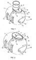
- Figure 1 shows a depositing tank.
- the depositing tank comprises a body 1, which is configured for allowing the container to be buried in the ground.
- the body 1 is made of plastic, such as polyethylene PE or polypropylene PP or some other suitable plastic material.
- the container further comprises an ascending tube 2 arranged in the body 1.
- the ascending tube 2 includes a tube part 3, which extends above the ground when the container is in use.
- the ascending tube 2 further includes a base 4 that is integral with the tube part 3.
- the ascending tube 2 is configured to be detachable from the body 1, whereby the ascending tube may be arranged partly inside the body 1 during the transport of the container in a manner shown in Figure 2 .
- the base 4 of the ascending tube 2 comprises a flange 5, and when the container is in use the ascending tube 2 is attached to the body 1, to a connecting end 6 provided in the body 1.
- the flange 5 is thus set over the connecting end 6.
- the connecting end 6 is a vertical collar that surrounds the hole in the upper part of the body 1.
- a seal is arranged between the flange 5 and the connecting end 6 such that the body 1 and the ascending tube 2 will be tightly fitted and the joint concerned will not leak.
- the flange 5 thus constitutes a sleeve that is arranged over the connecting end 6.
- the ascending tube 2 and the body 1 may also be interconnected with screws or bolts, whereby the base 4 may be designed to conform to the outer surface of the hole in the body 1 and a suitable seal is arranged between the base 4 and the body 1. Between the tube part 3 and the base 4 of the ascending tube 2 there is further provided a stiffening rib 7.
- the stiffening rib 7 reinforces the structure of the ascending tube 2.
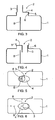
- Figure 3 also illustrates how the ascending tube 2 is arranged in connection with the body 1.
- the attaching figures show a depositing tank, in which there is a partition wall 8 or a plurality of partition walls 8 inside the container body 1.
- the partition walls 8 divide the interior of the container into chambers.
- the tube part 3 of the ascending tube 2 is arranged such that all chambers inside the container may be serviced through the ascending tube 3.
- Figures 4 and 6 illustrate how the eccentric placement of the tube part 3 of the ascending tube in the base 4 enables the tube part of the ascending tube being arranged in a chamber of the container during transport without the partition walls 8 preventing the tube part from being placed inside the container.
- partition walls 8 that remain invisible behind the ascending tube 2 and the container body 1 are indicated by broken lines.
- the tube part 3 may also be arranged in a centralized manner in relation to the base 4, but nevertheless the tube part could be placed inside a container chamber.
- the tube part 3 is arranged eccentrically to the base 4, a hole to be made in the body 1 need not be large as a whole, and yet it is possible to place the tube part inside the chamber.
- eccentricity makes it possible that during transport the base 4 is supported throughout to the rims of the hole in the container 1.
- the container 1 is still further provided with lugs 9, by means of which the ascending tube 2 may be secured firmly into place for transport. Said lugs may also be utilized for holding the ascending tube 2 in place, when the container is in normal use. It is possible to connect to the lugs 9 a strap, a rope or a binding line by which the ascending tube 2 is held in place.
- the container body 1 is further provided with a recess 10.
- the recess 10 may be arranged at the end of the body 1 and it is intended for accommodating a distribution well during transport. Namely, subsequent to the depositing tank there is typically arranged a separate distribution well.
- the distribution well to be transported to the installation site together with the depositing tank can be transported attached to the recess 10.
- the container further comprises a dowel pin 11.
- the dowel pin is designed in size and shape to correspond to a pipe that is inserted in an inlet of the distribution well.
- the distribution well inlet may be arranged in the dowel pin 11.
- the container body 1 further comprises lugs 12.
- the distribution well may be firmly attached to the body 1 by means of the dowel pin 11 and the lugs 12 for transport. Thanks to the dowel pin 11, two lugs 12, to which the strap, the rope or the connecting line are to be connected, will typically suffice for securing the distribution well.
- aligning element such as a rib, a notch or another suitable structural element.
- the aligning element is not necessarily supported to the inlet of the distribution well, but it may be supported to some other shape in the distribution well.
- transport mounts 13 On at least one side, i.e. flank, of the container body 1 there are arranged transport mounts 13. In a normal use position the container is naturally in a position shown in Figure 1 , i.e. the ascending tube 2 points upwardly. When the transport mounts 13 have been arranged on the side of the body 1, the container is transported to the installation site on its side, i.e. the transport mounts pointing downwardly.
- the transport mounts 13 may be arranged on the first side and additionally to a second side opposite to the first side. This allows a plurality of containers being superimposed during transport.
- the transport mounts 13 may be provided such that on the first side of the container the transport mounts are concave. It is thus advantageous to transport the container with these concave mounts downwardly.
- the transport mounts 13 on the other side of the container are convex. Then, the convex transport mounts 13 point upwardly during transport. It will be relatively easy to place another container with concave downwardly pointing transport mounts on top of the convex transport mounts 13. Consequently, the concave transport mounts 13 of the upper container will fit smoothly and firmly against the convex transport mounts 13 of the lower container.
- the container to which the presented features are applied may be, for instance, a depositing tank as indicated in the attached drawings.
- the container may be another container intended for installation in the ground, such as a sewage tank or any other liquid tank, a well, such as a distribution well, or a corresponding container or well.
- the container may be a depositing tank or a small-scale purifying plant or another corresponding container having two or more chambers inside the body.
- the ascending tube or a section thereof it is possible to transport inside the body also other parts or accessories relating to the container completely or such that part of them is located inside the body. These parts or accessories may include inlet and outlet connections, inlet and outlet pipes, filter bed pipes, joints and branches, etc.
- the ascending tube may also be mounted in its use position, and then the ascending tube will not be at all inside the body during transport. If the container body 1 is sufficiently large, it is possible to make the hole for the ascending tube base 4 in the body 1 so large that relatively large pieces may be transported in the interior of the body 1.
- the capacity of the body 1 may vary, for instance, between 500 and 5000 litres. If the capacity of the body 1 is sufficient, it is possible to transport a distribution well inside it, for instance.
Landscapes
- Engineering & Computer Science (AREA)
- Mechanical Engineering (AREA)
- Health & Medical Sciences (AREA)
- Life Sciences & Earth Sciences (AREA)
- Hydrology & Water Resources (AREA)
- Public Health (AREA)
- Water Supply & Treatment (AREA)
- Details Of Rigid Or Semi-Rigid Containers (AREA)
- Underground Structures, Protecting, Testing And Restoring Foundations (AREA)
- Electrical Discharge Machining, Electrochemical Machining, And Combined Machining (AREA)
- Supplying Of Containers To The Packaging Station (AREA)
- Treatment Of Biological Wastes In General (AREA)
- Laying Of Electric Cables Or Lines Outside (AREA)
- Springs (AREA)
- Loading And Unloading Of Fuel Tanks Or Ships (AREA)
- Filling Or Discharging Of Gas Storage Vessels (AREA)
Claims (10)
- Behälter, enthaltend einen Körper (1), der für eine unterirdische Installation eingerichtet ist, und ein aufsteigendes Rohr (2), das von dem Körper (1) lösbar ist, wobei im Inneren des Körpers (1) wenigstens eine Trennwand (8) derart vorhanden ist, dass der Behälter wenigstens zwei Kammern enthält und das aufsteigende Rohr (2) derart eingerichtet ist, dass die wenigstens zwei Kammern durch ein Loch versorgt werden können, das in dem Behälterkörper (1) vorgesehen ist, dadurch gekennzeichnet, dass
das aufsteigende Rohr (2) einen Rohrteil (3) und eine Basis (4) enthält, wobei die Basis größere Außenabmessungen als der Rohrteil, in der Achsrichtung des Rohrteils (3) betrachtet, aufweist und an dieser Basis (4) das aufsteigende Rohr (2) an dem Körper (1) angebracht ist, wobei das Loch des Behälterkörpers (1), in axialer Richtung betrachtet, größer ist als die Außenabmessung des Rohrteils (3), so dass das aufsteigende Rohr (2) das Loch des Behälterkörpers (1) durchlaufend wenigstens teilweise innerhalb einer der wenigstens zwei Kammern während des Transportes angeordnet sein kann. - Behälter nach Anspruch 1, dadurch gekennzeichnet, dass der Rohrteil des aufsteigenden Rohres (2) exzentrisch an der Basis (4) des aufsteigenden Rohres (2) angeordnet ist.
- Behälter nach einem der vorhergehenden Ansprüche, dadurch gekennzeichnet, dass
am Äußeren des Körpers (1) wenigstens ein Bügel (9) zum Sichern des aufsteigenden Rohres (2) angebracht ist. - Behälter nach einem der vorhergehenden Ansprüche, dadurch gekennzeichnet, dass
in dem Körper (1) auf der Außenseite desselben eine Aussparung (10) für den Transport eines Verteilerschachtes in Verbindung mit dem Behälter vorgesehen ist. - Behälter nach Anspruch 4, dadurch gekennzeichnet, dass ein Ausrichtelement (11) mit der Aussparung (10) verbunden ist, das dazu verwendet werden kann, den Verteilerschacht während des Transportes zu stützen.
- Behälter nach Anspruch 5, dadurch gekennzeichnet, dass das Ausrichtelement ein Passstift (11) ist, der in Größe und Form derart bemessen ist, dass er einem Rohr entspricht, dass in einen Einlass des Verteilerschachtes eingefügt werden soll.
- Behälter nach einem der vorhergehenden Ansprüche, dadurch gekennzeichnet, dass
ein Verteilerschacht für den Transport (1) innerhalb des Körpers angeordnet sein kann. - Behälter nach einem der vorhergehenden Ansprüche, dadurch gekennzeichnet, dass
auf der Außenseite des Körpers (1), wenigstens auf einer Seite desselben, Transporthalterungen (13) angebracht sind. - Behälter nach Anspruch 8, dadurch gekennzeichnet, dass
die Transporthalterungen (13) auf zwei gegenüberliegenden Seiten des Körpers (1) angebracht sind. - Behälter nach Anspruch 9, dadurch gekennzeichnet, dass
die Transporthalterungen (13) auf der ersten Seite des Körpers (1) konkav sind und die Transporthalterungen (13) auf der zweiten Seite des Körpers (1) konvex sind.
Priority Applications (3)
| Application Number | Priority Date | Filing Date | Title |
|---|---|---|---|
| EP10175413.3A EP2251277B8 (de) | 2005-12-23 | 2006-12-21 | Behälter für unterirdische Installation und Verfahren zum Transport eines solchen Behälters |
| DK10175413.3T DK2251277T3 (en) | 2005-12-23 | 2006-12-21 | Container for underground installation and method for transporting the same |
| PL10175413T PL2251277T3 (pl) | 2005-12-23 | 2006-12-21 | Zbiornik do montażu podziemnego i sposób jego transportu |
Applications Claiming Priority (1)
| Application Number | Priority Date | Filing Date | Title |
|---|---|---|---|
| FI20055700A FI20055700L (fi) | 2005-12-23 | 2005-12-23 | Säiliö |
Related Child Applications (2)
| Application Number | Title | Priority Date | Filing Date |
|---|---|---|---|
| EP10175413.3A Division EP2251277B8 (de) | 2005-12-23 | 2006-12-21 | Behälter für unterirdische Installation und Verfahren zum Transport eines solchen Behälters |
| EP10175413.3 Division-Into | 2010-09-06 |
Publications (3)
| Publication Number | Publication Date |
|---|---|
| EP1801035A1 EP1801035A1 (de) | 2007-06-27 |
| EP1801035B1 true EP1801035B1 (de) | 2010-09-08 |
| EP1801035B8 EP1801035B8 (de) | 2011-01-19 |
Family
ID=35510778
Family Applications (2)
| Application Number | Title | Priority Date | Filing Date |
|---|---|---|---|
| EP10175413.3A Active EP2251277B8 (de) | 2005-12-23 | 2006-12-21 | Behälter für unterirdische Installation und Verfahren zum Transport eines solchen Behälters |
| EP06126843A Active EP1801035B8 (de) | 2005-12-23 | 2006-12-21 | Behälter für unterirdische Installation |
Family Applications Before (1)
| Application Number | Title | Priority Date | Filing Date |
|---|---|---|---|
| EP10175413.3A Active EP2251277B8 (de) | 2005-12-23 | 2006-12-21 | Behälter für unterirdische Installation und Verfahren zum Transport eines solchen Behälters |
Country Status (7)
| Country | Link |
|---|---|
| EP (2) | EP2251277B8 (de) |
| AT (1) | ATE480480T1 (de) |
| DE (1) | DE602006016718D1 (de) |
| DK (2) | DK1801035T3 (de) |
| FI (1) | FI20055700L (de) |
| NO (1) | NO338752B1 (de) |
| PL (1) | PL2251277T3 (de) |
Families Citing this family (4)
| Publication number | Priority date | Publication date | Assignee | Title |
|---|---|---|---|---|
| DE102007020399B4 (de) * | 2007-04-27 | 2009-12-31 | Roth, Manfred, Dipl.-Volksw. | Tank, insbesondere Erdtank |
| PL2085326T3 (pl) * | 2008-02-04 | 2013-03-29 | Graf Plastics Gmbh | Sposób wytwarzania zbiornika z tworzywa sztucznego i zbiornik z tworzywa sztucznego |
| FI20165351A7 (fi) * | 2016-04-21 | 2017-10-22 | Oy U Cont Ltd | Intermodaalinen fluiditankki ja järjestelmä fluidin jakamiseksi |
| US11326335B2 (en) * | 2017-06-30 | 2022-05-10 | South East Water Corporation | Tank for pressure sewer installation |
Family Cites Families (12)
| Publication number | Priority date | Publication date | Assignee | Title |
|---|---|---|---|---|
| AU2684071A (de) * | 1971-04-06 | 1972-09-28 | ||
| DE9115953U1 (de) * | 1991-12-21 | 1992-02-27 | ABS Pumpen AG, 53797 Lohmar | Kugelförmiger Tank für Gase, Flüssigkeiten oder pasteuse Massen |
| JPH10174985A (ja) * | 1996-12-17 | 1998-06-30 | Sekisui Chem Co Ltd | 浄化槽 |
| US6024242A (en) * | 1996-12-24 | 2000-02-15 | Eidson Steel Products, Inc. | Removably insertable internal containment reservoir |
| JP4006744B2 (ja) * | 1997-09-30 | 2007-11-14 | 株式会社日立ハウステック | 嵩上枠及び浄化槽 |
| JP2000136540A (ja) * | 1998-10-30 | 2000-05-16 | Shikoku Sanyu Kasei Kk | 大型浄化槽用マンホール立上り枠 |
| DE19911009A1 (de) * | 1999-03-12 | 2000-09-14 | Fusion Kunststoff Gmbh | Regenwassersammeltank |
| BE1013186A6 (nl) * | 1999-12-21 | 2001-10-02 | Tank Shop Jan Verbeeck B V B A | Brandstoftank voor ondergronds gebruik. |
| JP2002309631A (ja) * | 2001-04-17 | 2002-10-23 | Ishikawajima Constr Materials Co Ltd | 水 槽 |
| US20040188447A1 (en) * | 2002-01-23 | 2004-09-30 | Todd Bolzer | Underground storage tank |
| US7178686B2 (en) * | 2002-01-23 | 2007-02-20 | Snyder Industries | Rotationally molded subterranean tank with riser |
| DE202004008058U1 (de) * | 2004-05-17 | 2004-07-22 | Vtg-Lehnkering Reederei Gmbh | Transport- und Lagerbehälter |
-
2005
- 2005-12-23 FI FI20055700A patent/FI20055700L/fi not_active Application Discontinuation
-
2006
- 2006-12-21 DK DK06126843.9T patent/DK1801035T3/da active
- 2006-12-21 EP EP10175413.3A patent/EP2251277B8/de active Active
- 2006-12-21 DK DK10175413.3T patent/DK2251277T3/en active
- 2006-12-21 EP EP06126843A patent/EP1801035B8/de active Active
- 2006-12-21 DE DE602006016718T patent/DE602006016718D1/de active Active
- 2006-12-21 AT AT06126843T patent/ATE480480T1/de not_active IP Right Cessation
- 2006-12-21 PL PL10175413T patent/PL2251277T3/pl unknown
- 2006-12-22 NO NO20065986A patent/NO338752B1/no unknown
Also Published As
| Publication number | Publication date |
|---|---|
| PL2251277T3 (pl) | 2015-10-30 |
| EP2251277B1 (de) | 2015-04-15 |
| NO338752B1 (no) | 2016-10-17 |
| DE602006016718D1 (de) | 2010-10-21 |
| FI20055700A7 (fi) | 2007-06-24 |
| FI20055700L (fi) | 2007-06-24 |
| DK1801035T3 (da) | 2010-12-06 |
| EP1801035A1 (de) | 2007-06-27 |
| EP2251277B8 (de) | 2015-06-17 |
| EP1801035B8 (de) | 2011-01-19 |
| ATE480480T1 (de) | 2010-09-15 |
| EP2251277A1 (de) | 2010-11-17 |
| NO20065986L (no) | 2007-06-25 |
| FI20055700A0 (fi) | 2005-12-23 |
| DK2251277T3 (en) | 2015-07-13 |
Similar Documents
| Publication | Publication Date | Title |
|---|---|---|
| CA2714329C (en) | Storage tank containment apparatus | |
| CA2314819C (en) | Septic waste treatment system | |
| US6520124B2 (en) | Double walled fuel tank with integral generator set mounting frame | |
| US8292117B2 (en) | Stackable water holding tank | |
| US9377032B2 (en) | Mobile concrete pump | |
| US11548725B2 (en) | Cover systems, tank covering methods, and pipe retention systems | |
| US11230853B2 (en) | Large capacity above ground impoundment tank | |
| EP2251277B1 (de) | Behälter für unterirdische Installation und Verfahren zum Transport eines solchen Behälters | |
| US20070164552A1 (en) | Fluid containment system | |
| US7000800B2 (en) | Storage tank assembly | |
| US20130160860A1 (en) | Load box for storage tank containment | |
| US5609267A (en) | Corrosion-resistant storage tank for runoff liquids | |
| US12037878B2 (en) | Adapter assembly, flowline connector assembly and subsea production system | |
| US11009178B2 (en) | Pump package frame | |
| JPH0436230B2 (de) | ||
| JPH11208772A (ja) | 地下埋設貯液容器 | |
| EP2685108B1 (de) | Öltank | |
| WO2017127894A1 (en) | Improvements in the discharge of bulk liquids | |
| JPH1179284A (ja) | 地下埋設燃料容器 | |
| RU15899U1 (ru) | Многосекционный проходной колодец | |
| JP2009174595A (ja) | 継手 | |
| HK1087079B (en) | Method of fitting liquid container bag body, and liquid container | |
| HK1087079A1 (zh) | 液体货运箱的袋体的组装方法以及液体货运箱 | |
| ITBA20070069U1 (it) | Contenitore in lamiera installato direttamente sulla lamiera di un serbatoio di stoccaggio all'interno del quale vengono installati tutti gli impianti meccanici, elettrici, elettronici e pneumatici per un corretto funzionamento dell'impianto destinat |
Legal Events
| Date | Code | Title | Description |
|---|---|---|---|
| PUAI | Public reference made under article 153(3) epc to a published international application that has entered the european phase |
Free format text: ORIGINAL CODE: 0009012 |
|
| AK | Designated contracting states |
Kind code of ref document: A1 Designated state(s): AT BE BG CH CY CZ DE DK EE ES FI FR GB GR HU IE IS IT LI LT LU LV MC NL PL PT RO SE SI SK TR |
|
| AX | Request for extension of the european patent |
Extension state: AL BA HR MK YU |
|
| 17P | Request for examination filed |
Effective date: 20071211 |
|
| RAP1 | Party data changed (applicant data changed or rights of an application transferred) |
Owner name: UPONOR INNOVATION AB |
|
| 17Q | First examination report despatched |
Effective date: 20080115 |
|
| AKX | Designation fees paid |
Designated state(s): AT BE BG CH CY CZ DE DK EE ES FI FR GB GR HU IE IS IT LI LT LU LV MC NL PL PT RO SE SI SK TR |
|
| GRAP | Despatch of communication of intention to grant a patent |
Free format text: ORIGINAL CODE: EPIDOSNIGR1 |
|
| RIN1 | Information on inventor provided before grant (corrected) |
Inventor name: STRAND, JOHAN Inventor name: TAST, NIILA Inventor name: FORSSELL, FREDRIK |
|
| GRAS | Grant fee paid |
Free format text: ORIGINAL CODE: EPIDOSNIGR3 |
|
| GRAA | (expected) grant |
Free format text: ORIGINAL CODE: 0009210 |
|
| AK | Designated contracting states |
Kind code of ref document: B1 Designated state(s): AT BE BG CH CY CZ DE DK EE ES FI FR GB GR HU IE IS IT LI LT LU LV MC NL PL PT RO SE SI SK TR |
|
| REG | Reference to a national code |
Ref country code: GB Ref legal event code: FG4D |
|
| REG | Reference to a national code |
Ref country code: CH Ref legal event code: EP |
|
| RAP2 | Party data changed (patent owner data changed or rights of a patent transferred) |
Owner name: UPONOR INNOVATION AB |
|
| REG | Reference to a national code |
Ref country code: IE Ref legal event code: FG4D |
|
| REF | Corresponds to: |
Ref document number: 602006016718 Country of ref document: DE Date of ref document: 20101021 Kind code of ref document: P |
|
| REG | Reference to a national code |
Ref country code: SE Ref legal event code: TRGR |
|
| REG | Reference to a national code |
Ref country code: DK Ref legal event code: T3 |
|
| REG | Reference to a national code |
Ref country code: NL Ref legal event code: VDEP Effective date: 20100908 |
|
| PG25 | Lapsed in a contracting state [announced via postgrant information from national office to epo] |
Ref country code: AT Free format text: LAPSE BECAUSE OF FAILURE TO SUBMIT A TRANSLATION OF THE DESCRIPTION OR TO PAY THE FEE WITHIN THE PRESCRIBED TIME-LIMIT Effective date: 20100908 |
|
| PG25 | Lapsed in a contracting state [announced via postgrant information from national office to epo] |
Ref country code: SI Free format text: LAPSE BECAUSE OF FAILURE TO SUBMIT A TRANSLATION OF THE DESCRIPTION OR TO PAY THE FEE WITHIN THE PRESCRIBED TIME-LIMIT Effective date: 20100908 Ref country code: PL Free format text: LAPSE BECAUSE OF FAILURE TO SUBMIT A TRANSLATION OF THE DESCRIPTION OR TO PAY THE FEE WITHIN THE PRESCRIBED TIME-LIMIT Effective date: 20100908 Ref country code: CY Free format text: LAPSE BECAUSE OF FAILURE TO SUBMIT A TRANSLATION OF THE DESCRIPTION OR TO PAY THE FEE WITHIN THE PRESCRIBED TIME-LIMIT Effective date: 20100908 |
|
| PG25 | Lapsed in a contracting state [announced via postgrant information from national office to epo] |
Ref country code: GR Free format text: LAPSE BECAUSE OF FAILURE TO SUBMIT A TRANSLATION OF THE DESCRIPTION OR TO PAY THE FEE WITHIN THE PRESCRIBED TIME-LIMIT Effective date: 20101209 Ref country code: NL Free format text: LAPSE BECAUSE OF FAILURE TO SUBMIT A TRANSLATION OF THE DESCRIPTION OR TO PAY THE FEE WITHIN THE PRESCRIBED TIME-LIMIT Effective date: 20100908 |
|
| PG25 | Lapsed in a contracting state [announced via postgrant information from national office to epo] |
Ref country code: SK Free format text: LAPSE BECAUSE OF FAILURE TO SUBMIT A TRANSLATION OF THE DESCRIPTION OR TO PAY THE FEE WITHIN THE PRESCRIBED TIME-LIMIT Effective date: 20100908 Ref country code: PT Free format text: LAPSE BECAUSE OF FAILURE TO SUBMIT A TRANSLATION OF THE DESCRIPTION OR TO PAY THE FEE WITHIN THE PRESCRIBED TIME-LIMIT Effective date: 20110110 Ref country code: RO Free format text: LAPSE BECAUSE OF FAILURE TO SUBMIT A TRANSLATION OF THE DESCRIPTION OR TO PAY THE FEE WITHIN THE PRESCRIBED TIME-LIMIT Effective date: 20100908 Ref country code: CZ Free format text: LAPSE BECAUSE OF FAILURE TO SUBMIT A TRANSLATION OF THE DESCRIPTION OR TO PAY THE FEE WITHIN THE PRESCRIBED TIME-LIMIT Effective date: 20100908 Ref country code: IT Free format text: LAPSE BECAUSE OF FAILURE TO SUBMIT A TRANSLATION OF THE DESCRIPTION OR TO PAY THE FEE WITHIN THE PRESCRIBED TIME-LIMIT Effective date: 20100908 Ref country code: IS Free format text: LAPSE BECAUSE OF FAILURE TO SUBMIT A TRANSLATION OF THE DESCRIPTION OR TO PAY THE FEE WITHIN THE PRESCRIBED TIME-LIMIT Effective date: 20110108 |
|
| PG25 | Lapsed in a contracting state [announced via postgrant information from national office to epo] |
Ref country code: ES Free format text: LAPSE BECAUSE OF FAILURE TO SUBMIT A TRANSLATION OF THE DESCRIPTION OR TO PAY THE FEE WITHIN THE PRESCRIBED TIME-LIMIT Effective date: 20101219 Ref country code: BE Free format text: LAPSE BECAUSE OF FAILURE TO SUBMIT A TRANSLATION OF THE DESCRIPTION OR TO PAY THE FEE WITHIN THE PRESCRIBED TIME-LIMIT Effective date: 20100908 |
|
| PLBE | No opposition filed within time limit |
Free format text: ORIGINAL CODE: 0009261 |
|
| STAA | Information on the status of an ep patent application or granted ep patent |
Free format text: STATUS: NO OPPOSITION FILED WITHIN TIME LIMIT |
|
| PG25 | Lapsed in a contracting state [announced via postgrant information from national office to epo] |
Ref country code: MC Free format text: LAPSE BECAUSE OF NON-PAYMENT OF DUE FEES Effective date: 20101231 |
|
| REG | Reference to a national code |
Ref country code: CH Ref legal event code: PL |
|
| 26N | No opposition filed |
Effective date: 20110609 |
|
| GBPC | Gb: european patent ceased through non-payment of renewal fee |
Effective date: 20101221 |
|
| REG | Reference to a national code |
Ref country code: FR Ref legal event code: ST Effective date: 20110831 |
|
| REG | Reference to a national code |
Ref country code: DE Ref legal event code: R097 Ref document number: 602006016718 Country of ref document: DE Effective date: 20110609 |
|
| PG25 | Lapsed in a contracting state [announced via postgrant information from national office to epo] |
Ref country code: CH Free format text: LAPSE BECAUSE OF NON-PAYMENT OF DUE FEES Effective date: 20101231 Ref country code: LI Free format text: LAPSE BECAUSE OF NON-PAYMENT OF DUE FEES Effective date: 20101231 Ref country code: FR Free format text: LAPSE BECAUSE OF NON-PAYMENT OF DUE FEES Effective date: 20110103 Ref country code: IE Free format text: LAPSE BECAUSE OF NON-PAYMENT OF DUE FEES Effective date: 20101221 |
|
| PG25 | Lapsed in a contracting state [announced via postgrant information from national office to epo] |
Ref country code: GB Free format text: LAPSE BECAUSE OF NON-PAYMENT OF DUE FEES Effective date: 20101221 |
|
| PG25 | Lapsed in a contracting state [announced via postgrant information from national office to epo] |
Ref country code: HU Free format text: LAPSE BECAUSE OF FAILURE TO SUBMIT A TRANSLATION OF THE DESCRIPTION OR TO PAY THE FEE WITHIN THE PRESCRIBED TIME-LIMIT Effective date: 20110309 Ref country code: BG Free format text: LAPSE BECAUSE OF FAILURE TO SUBMIT A TRANSLATION OF THE DESCRIPTION OR TO PAY THE FEE WITHIN THE PRESCRIBED TIME-LIMIT Effective date: 20100908 Ref country code: LU Free format text: LAPSE BECAUSE OF NON-PAYMENT OF DUE FEES Effective date: 20101221 |
|
| PG25 | Lapsed in a contracting state [announced via postgrant information from national office to epo] |
Ref country code: TR Free format text: LAPSE BECAUSE OF FAILURE TO SUBMIT A TRANSLATION OF THE DESCRIPTION OR TO PAY THE FEE WITHIN THE PRESCRIBED TIME-LIMIT Effective date: 20100908 |
|
| PG25 | Lapsed in a contracting state [announced via postgrant information from national office to epo] |
Ref country code: BG Free format text: LAPSE BECAUSE OF FAILURE TO SUBMIT A TRANSLATION OF THE DESCRIPTION OR TO PAY THE FEE WITHIN THE PRESCRIBED TIME-LIMIT Effective date: 20101208 |
|
| PGFP | Annual fee paid to national office [announced via postgrant information from national office to epo] |
Ref country code: LT Payment date: 20151120 Year of fee payment: 10 Ref country code: EE Payment date: 20151211 Year of fee payment: 10 Ref country code: DE Payment date: 20151211 Year of fee payment: 10 |
|
| PGFP | Annual fee paid to national office [announced via postgrant information from national office to epo] |
Ref country code: LV Payment date: 20151211 Year of fee payment: 10 |
|
| REG | Reference to a national code |
Ref country code: DE Ref legal event code: R119 Ref document number: 602006016718 Country of ref document: DE |
|
| REG | Reference to a national code |
Ref country code: LT Ref legal event code: MM4D Effective date: 20161221 |
|
| REG | Reference to a national code |
Ref country code: EE Ref legal event code: MM4A Ref document number: E004857 Country of ref document: EE Effective date: 20161231 |
|
| PG25 | Lapsed in a contracting state [announced via postgrant information from national office to epo] |
Ref country code: LT Free format text: LAPSE BECAUSE OF NON-PAYMENT OF DUE FEES Effective date: 20161221 |
|
| PG25 | Lapsed in a contracting state [announced via postgrant information from national office to epo] |
Ref country code: LV Free format text: LAPSE BECAUSE OF NON-PAYMENT OF DUE FEES Effective date: 20161221 |
|
| PG25 | Lapsed in a contracting state [announced via postgrant information from national office to epo] |
Ref country code: EE Free format text: LAPSE BECAUSE OF NON-PAYMENT OF DUE FEES Effective date: 20161231 |
|
| PG25 | Lapsed in a contracting state [announced via postgrant information from national office to epo] |
Ref country code: DE Free format text: LAPSE BECAUSE OF NON-PAYMENT OF DUE FEES Effective date: 20170701 |
|
| PGFP | Annual fee paid to national office [announced via postgrant information from national office to epo] |
Ref country code: DK Payment date: 20171215 Year of fee payment: 12 |
|
| REG | Reference to a national code |
Ref country code: DK Ref legal event code: EBP Effective date: 20181231 |
|
| PG25 | Lapsed in a contracting state [announced via postgrant information from national office to epo] |
Ref country code: DK Free format text: LAPSE BECAUSE OF NON-PAYMENT OF DUE FEES Effective date: 20181231 |
|
| P01 | Opt-out of the competence of the unified patent court (upc) registered |
Effective date: 20230602 |
|
| PGFP | Annual fee paid to national office [announced via postgrant information from national office to epo] |
Ref country code: FI Payment date: 20251223 Year of fee payment: 20 |
|
| PGFP | Annual fee paid to national office [announced via postgrant information from national office to epo] |
Ref country code: SE Payment date: 20251219 Year of fee payment: 20 |