EP1800639B1 - Tragbarer einwegartikel - Google Patents
Tragbarer einwegartikel Download PDFInfo
- Publication number
- EP1800639B1 EP1800639B1 EP05793195A EP05793195A EP1800639B1 EP 1800639 B1 EP1800639 B1 EP 1800639B1 EP 05793195 A EP05793195 A EP 05793195A EP 05793195 A EP05793195 A EP 05793195A EP 1800639 B1 EP1800639 B1 EP 1800639B1
- Authority
- EP
- European Patent Office
- Prior art keywords
- proximal end
- wearing article
- lateral margin
- waist region
- transverse direction
- Prior art date
- Legal status (The legal status is an assumption and is not a legal conclusion. Google has not performed a legal analysis and makes no representation as to the accuracy of the status listed.)
- Not-in-force
Links
Images


Classifications
-
- A—HUMAN NECESSITIES
- A61—MEDICAL OR VETERINARY SCIENCE; HYGIENE
- A61F—FILTERS IMPLANTABLE INTO BLOOD VESSELS; PROSTHESES; DEVICES PROVIDING PATENCY TO, OR PREVENTING COLLAPSING OF, TUBULAR STRUCTURES OF THE BODY, e.g. STENTS; ORTHOPAEDIC, NURSING OR CONTRACEPTIVE DEVICES; FOMENTATION; TREATMENT OR PROTECTION OF EYES OR EARS; BANDAGES, DRESSINGS OR ABSORBENT PADS; FIRST-AID KITS
- A61F13/00—Bandages or dressings; Absorbent pads
- A61F13/15—Absorbent pads, e.g. sanitary towels, swabs or tampons for external or internal application to the body; Supporting or fastening means therefor; Tampon applicators
- A61F13/56—Supporting or fastening means
- A61F13/5622—Supporting or fastening means specially adapted for diapers or the like
- A61F13/5633—Supporting or fastening means specially adapted for diapers or the like open type diaper
-
- A—HUMAN NECESSITIES
- A61—MEDICAL OR VETERINARY SCIENCE; HYGIENE
- A61F—FILTERS IMPLANTABLE INTO BLOOD VESSELS; PROSTHESES; DEVICES PROVIDING PATENCY TO, OR PREVENTING COLLAPSING OF, TUBULAR STRUCTURES OF THE BODY, e.g. STENTS; ORTHOPAEDIC, NURSING OR CONTRACEPTIVE DEVICES; FOMENTATION; TREATMENT OR PROTECTION OF EYES OR EARS; BANDAGES, DRESSINGS OR ABSORBENT PADS; FIRST-AID KITS
- A61F13/00—Bandages or dressings; Absorbent pads
- A61F13/15—Absorbent pads, e.g. sanitary towels, swabs or tampons for external or internal application to the body; Supporting or fastening means therefor; Tampon applicators
- A61F13/15203—Properties of the article, e.g. stiffness or absorbency
-
- A—HUMAN NECESSITIES
- A61—MEDICAL OR VETERINARY SCIENCE; HYGIENE
- A61F—FILTERS IMPLANTABLE INTO BLOOD VESSELS; PROSTHESES; DEVICES PROVIDING PATENCY TO, OR PREVENTING COLLAPSING OF, TUBULAR STRUCTURES OF THE BODY, e.g. STENTS; ORTHOPAEDIC, NURSING OR CONTRACEPTIVE DEVICES; FOMENTATION; TREATMENT OR PROTECTION OF EYES OR EARS; BANDAGES, DRESSINGS OR ABSORBENT PADS; FIRST-AID KITS
- A61F13/00—Bandages or dressings; Absorbent pads
- A61F13/15—Absorbent pads, e.g. sanitary towels, swabs or tampons for external or internal application to the body; Supporting or fastening means therefor; Tampon applicators
- A61F13/56—Supporting or fastening means
- A61F13/62—Mechanical fastening means, ; Fabric strip fastener elements, e.g. hook and loop
- A61F13/622—Fabric strip fastener elements, e.g. hook and loop
Definitions
- the present invention relates to a disposable wearing article suitable for use in various forms such as a disposable diaper, a disposable diaper for incontinent patient, a disposable diaper cover and disposable training pants.
- Disposable diapers having front and rear waist regions adapted to be detachably connected with each other by sheet-like fasteners are well known.
- each of the fasteners has its one end as viewed in a transverse direction of the diaper is permanently bonded to one of front and rear waist regions in the vicinity of the associated one of transversely opposite side edges.
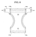
- the disposable diaper 100 of this type shown in Figs. 5 and 6 is disclosed, for example, in Japanese Patent No. 3096152 (PATENT DOCUMENT 1).
- the diaper 100 has a pair of connector sheet strips as fasteners.
- Transversely opposite side edges 103, 103 of the front waist region 101 and transversely opposite side edges 104, 104 of the rear waist region 102 are put flat together, then proximal ends 107, 107 of the respective connector sheet strips 106, 106 having distal ends provided on inner surfaces with engagement members 105 are put flat together with the transversely opposite side edges 103, 103 of the front waist region 101.
- These portions put flat together are bonded together to define joint zones 108.
- the front waist region 101 is formed with cutting lines 109a, 109a along which the front waist region 101 is cut off from the rear waist region 102.
- this diaper 100 initially has the pants-type and may be put on the wearer's body without any modification when it is desired to put the diaper 100 on the wearer standing up.
- the connector sheet strips 106 are not used and locked on the front waist region 101 by means of the engagement members 105 without an anxiety that these connector sheet strips 106 might unintentionally move during use of the diaper 100.
- the front waist region 101 or the connector sheet strips 106 may be pulled so as to tear the front waist region 101 off from the rear waist region 102 along the cutting lines 109a and thereby to convert the diaper 101 from the initial pants-type to the open-type as shown in Fig. 6 .
- the connector sheet strips 106 may be anchored on the front waist region 101 at appropriate positions.
- the transversely opposite side edges 103, 103 of the front waist region 101, the transversely opposite side edges 104, 104 of the rear waist region 102 and the proximal ends 107, 107 of the respective connector sheet strips 106 are put flat and bonded together wherein the distal ends of the respective connector sheet strips 106, 106 including the engagement members 105, 105 attached thereto extend toward middle of the front waist region 101 as shown in Fig. 5 .
- the connector sheet strips 106 must be turned around from the position in Fig. 5 to the position in Fig.
- a wearing article including a pair of connector sheet strips extending inward from transversely opposite side edges of the wearing article and serving as fastener means to connect front and rear waist regions improved so that the connector sheet strips can be easily turned around so as to extend outward from the side edges.
- a disposable wearing article having a back-and-forth direction and a transverse direction orthogonal to the back-and-forth direction
- the disposable wearing article comprising a crotch region, a front waist region lying in front of the crotch region and a rear waist region lying behind the crotch region, each of these regions has a pair of side edges opposed to each other in the transverse direction and extending in the back-and-forth direction, the front and rear waist regions having front and rear ends, respectively, opposed to each other in the back-and-forth direction and extending in the transverse direction, and one of the front and rear waist regions being provided on lateral margins extending along the side edges with connector sheet strips adapted to be detachably secured to the other waist region.
- Such wearing article further comprises a construction as follows:
- Each of the connector sheet strips comprises a proximal end overlapped and bonded together with the lateral margin on an inner surface of the wearing article destined to face a wearer's body of the wearing article and a deformable flap portion extending inward in the transverse direction from the proximal end and provided on the inner surface with fastening means adapted to act upon an outer surface of the other waist region opposed to the inner surface.
- the proximal end and the lateral margin contain a thermoplastic polymer to ensure that solidification following melting of the thermoplastic polymer integrates the proximal end with the lateral margin in a curved structure wherein the proximal end lies on a convex side and the lateral margin lies on a concave side.
- the proximal end and the lateral margin having been integrated with each other present a flexural stiffness in the transverse direction higher than a flexural stiffness presented by an inside region of the wearing article contiguous to the lateral margin.
- the proximal end of the connector sheet strip and the associated lateral margin of the wearing article are integrally bonded together to form the curved structure wherein the proximal end of the connector sheet strip lies on a convex side and the lateral margin lies on a concave side.
- the flap portion of the connector sheet strip extending inward in the transverse direction of the wearing article can be easily turned around so as to extend outward in the transverse direction of the wearing article.
- the proximal end of the connector sheet strip and the lateral margin are bonded together to form the integrated structure presenting a flexural stiffness in the transverse direction higher than a flexural stiffness presented by the inside region of the wearing article contiguous to the lateral margin. Consequently, the connector sheet strip can be easily turned around without being affected by deformation occurring in this inside region.
- a disposable diaper 1 shown in Fig. 1 in a partially cutaway perspective view is of a type suitable for baby and comprises a chassis 2 and a bodily fluid absorbent pad 3.
- the chassis 2 has a crotch region 8, a front waist region 6 extending forward from the crotch region 8 and a rear waist region 7 extending rearward from the crotch region 8.
- These regions 6, 7, 8 are respectively formed from an outer sheet 5 defined by a first sheet facing the wearer's garment (not shown) and an inner sheet 4 defined by a second sheet lying on the opposite side of the outer sheet 5 and facing the wearer's body.
- Connector sheet strips 9 defined by a third sheet prepared separately of the inner and outer sheets 4, 5 are put flat together with respective lateral margins 50 extending along transversely opposite side edges 12 of the rear waist region 7 and secured to these lateral margins 50 at a plurality of welding spots 13 thereof arranged intermittently in a vertical direction as viewed in Fig. 1 .
- Each of these connector sheet strips 9 is relatively long in the vertical direction as viewed in Fig. 1 and has inner and outer surfaces 9a, 9b wherein a loop member 16 of a mechanical fastener commonly known under Trademark "MAGIC TAPE” or "VELCRO" is attached to the inner surface 9a by means of a suitable adhesive or welding technique.
- a hook member 17 of the mechanical fastener is attached to the outer sheet 5 by means of a suitable adhesive or welding technique.
- the front and rear waist regions 6, 7 are detachably connected with each other by means of the connector sheet strips 9 as these loop members 16 and hook members 17 serving as fastening means are engaged together.
- Fig. 1 shows the front and rear waist regions 6, 7 being in mutually connected state at the right side and in still not mutually connected state at the left side.
- a waist-hole 18 and a pair of leg-holes 19 are formed as the front and rear waist regions 6, 7 are connected with each other on both sides.
- the connector sheet strip 9 has a proximal end 51 secured to the lateral margin 50 of the rear waist region 6 and a deformable flap portion 52 extending toward a longitudinal axis C-C bisecting a width of the front waist region 6.
- the proximal end 51 extends transversely outward with respect to the diaper 1 integrally with the lateral margin 50 and the flap portion 52 extends transversely inward from the proximal end 51.
- a fold line 55 appears between the proximal end 51 and the flap portion 52 respectively extending in the directions which are opposite to each other.
- the loop member 16 is attached to the flap portion 52 and a finger-grip 54 is defined by a forward extremity of the flap portion 52 as viewed in a waist-surrounding direction.
- a finger-grip 54 is defined by a forward extremity of the flap portion 52 as viewed in a waist-surrounding direction.
- the proximal end 51 lies on a convex side and the lateral margin 50 lies on a concave side.
- the diaper 1 further includes a waist elastic members 20 circumferentially extending along the waist-hole 18 and leg-hole elastic members 19a circumferentially extending along the respective leg-holes 19.
- the chassis 2 is formed with a plurality of gathers 66, 67 each extending orthogonally to the elastic members 20, 19a, respectively, so as to make repetitive undulation along the respective elastic members 20, 19a as these elastic members 20, 19a are left to contract.
- Fig. 2 is a partially cutaway perspective view showing the diaper 1 of Fig. 1 with the front and rear waist regions 6, 7 disconnected from each other and developed in a transverse direction indicated by a double-headed arrow x as well as in a back-and-forth direction indicated by a double-headed arrow Y insomuch as the gathers 66, 67 do not completely disappear.
- the transverse direction X corresponds to the waist-surrounding direction of the diaper 1.
- the chassis 2 as a whole has a pair of side edges 10 opposed in the transverse direction X and extending in the back-and-forth direction Y.
- a width between a pair of transversely opposite segments 11 extending in the front waist region 6 is dimensioned to be smaller than a width between another pair of transversely opposite segments 12 extending in the rear waist region 7.
- a pair of transversely opposite segments 28 of the side edges 10, extending in the crotch region 8 describe circular arcs which are convex inward with respect to the chassis 2.
- the front and rear waist regions 6, 7 respectively have front and rear ends 26, 27 opposed to each other in the back-and-forth direction Y and extending in the transverse direction X. These front and rear ends 26, 27 cooperate to define a periphery of the waist-hole 18 when the front and rear waist regions 6, 7 are connected with each other as seen in Fig. 1 .
- the waist elastic members 20 provided on the chassis 2 comprise, in addition to at least single first elastic member 21a for the front waist region 6 extending in stretched state along the front end 26 between the opposite side edges 11, 11, and at least single first elastic member 21b for the rear waist region 7 extending in stretched state along the rear end 27 between the opposite side edges 12, 12, a plurality of second elastic members 22a, 22b for the front and rear waist region 6, 7 both lying below the first elastic members 21a, 21b and above the side edges 28 of the crotch region 8 and extending in stretched state between the opposite side edges 11, 11 and between the opposite side edges 12, 12, respectively.
- the first respective elastic members 21a, 21b are respectively adapted to tighten up the wearer's waist more firmly than the respective second elastic members 22a, 22b respectively can.
- the elastic members presenting a tensile stress higher than the respective second elastic members 22a, 22b are used as the respective first elastic members 21a, 21b. It is possible without departing from the scope of the invention to eliminate the second elastic member 22a and/or the second elastic member 22b.
- the chassis 2 is further provided along the side edges 28 of the crotch region 8 with leg elastic members 19a. These waist elastic members 20 and leg elastic members 19a are interposed between the inner sheet 4 and the outer sheet 5 and bonded to at least one of these two sheets 4, 5 preferably intermittently.
- the bodily fluid absorbent pad 3 comprises a liquid-pervious upper sheet 32, a liquid-impervious lower sheet 33 and a bodily fluid absorbent core 34 sandwiched between these two sheets 32, 33.
- the upper and lower sheets 32, 33 extend outward beyond a peripheral edge of the core 34 and overlapped and bonded together outside the peripheral edge by means of a adhesive or welding technique.
- the bodily fluid absorbent pad 3 is provided along transversely opposite side edges thereof with leak barriers 36 preferably made of a liquid-impervious sheet. Each of the leak barriers 36 is bonded along its front and rear ends 37, 38 and outer side edge 39 to the upper sheet 32 but left free along its inner side edge from the upper sheet 32.
- the inner side edge 41 is provided with an elastic member 42 extending in the back-and-forth direction Y and attached in stretched state thereto.
- the leak barrier 36 arranged in this manner defines a pocket 43 adapted to receive bodily fluids moving on the upper sheet 32 in the transverse direction X.
- the body fluid absorbent pad 3 has its lower sheet 33 bonded to the inner sheet 4 of the chassis 2 by means of a hot melt adhesive (not shown).
- both the inner sheet 4 and the outer sheet 5 have a basis weight in a range of about 10 to about 50g/m 2 and may be, for example, a nonwoven fabric or film made of a thermoplastic polymer or composite sheet consisting of these nonwoven fabric and film laminated together so far as the thermoplastic polymer is contained therein as an essential ingredient.
- the upper sheet 32 of the bodily fluid absorbent pad 3 has a basis weight of about 10 to about 30g/m 2 may be, for example, a nonwoven fabric or perforated film made of thermoplastic polymer and the lower sheet 33 may be, for example, a film or nonwoven fabric made of a thermoplastic polymer or composite sheet consisting of these film and nonwoven fabric laminated together.
- the core 34 may be formed by, for example, fluff pulp, or a mixture of fluff pulp and super-absorbent polymer particles compressed to an appropriate thickness and then wrapped with a highly liquid-pervious and liquid-diffusive sheet such as a tissue paper.
- the connector sheet strip 9 has a basis weight in a range of about 15 to about 200g/m 2 and may be, for example, a nonwoven fabric made of a thermoplastic polymer, film made of a thermoplastic polymer or composite sheet consisting of these nonwoven fabric and film laminated together so far as the thermoplastic polymer is contained therein as essential ingredient.
- Fig. 3 us a sectional view taken along the line III-III in Fig. 1 , wherein the line III-III passes through the welding spots 13.
- the inner sheet 4, the outer sheet 5 and the connector sheet strip 9 are heated under a pressure so that the thermoplastic polymer contained in these sheets is molten and then these sheets are integrally welded together at the welded spots 13 as the thermoplastic polymer is solidified preferably in film-like state.
- the lateral margin 50 of the rear waist region 7 including such welding spots 13 describes a curvature so that the proximal end 51 of the connector sheet strip 9 lies on the convex side and the lateral margin 50 of the outer sheet 5 lies on the concave side. Also the non-welded portions 61 between respective pairs of the welding spots 13 successively adjacent in the vertical direction as viewed in Fig. 1 left free from each other follow such curvature. Consequentially, these integrated proximal end 51 and the lateral margin 50 curve downward as viewed in Fig. 1 , in other words, toward the rear waist region 7 until the outermost portion of this curve in the transverse direction X is significantly placed aside toward the rear waist region 7 (See Fig. 1 ).
- the lateral margin 50 itself comprising the inner and outer sheets 4, 5 overlapped and bonded together is then welded integrally with the connector sheet strip 9 at the welding spots 13 and thereby obtains a flexural stiffness higher that a flexural stiffness of an inside region 65 of the wearing article 1 comprising the inner and outer sheets 4, 5 placed upon each other and is contiguous to the lateral margin 50.
- the lateral margin 50 is not readily flexed.
- the flap portion 52 of the connector sheet strip 9 may be pulled in a direction indicated by an arrow P to invert the loop member 16 and, in response thereto, the lateral margin 50 moves together with the proximal end 51 in a direction indicated by arrow Q.
- the connector sheet strip 9 facilitates the flap portion 52 to extend outward in the transverse direction X, as seen in Fig. 2 , and in Fig. 4 as will be described later.
- Such movement of the connector sheet strip 9 can be further facilitated by adjusting a flexural stiffness of the flap portion 52 in the transverse direction X to be higher than a flexural stiffness of the inside region 65 of the wearing article 1 which is contiguous to the lateral margin 50 and merely comprises the inner and outer sheets 4, 5 placed upon each other.
- a sheet material having the correspondingly high flexural stiffness may be used as the connector sheet strip 9 or, if the connector sheet strip 9 has not a sufficiently high flexural stiffness, the loop member 16 may be attached to the flap portion 52 over substantially its entire inner surface 9a.
- the fold line 55 appears between the flap portion 52 and the proximal end 51 having a flexural stiffness higher than a flexural stiffness of the flap portion 52.
- Fig. 4 is a sectional view taken along the line IV-IV in Fig. 2 .
- the lateral margin 50 of the rear waist region 7 is folded back so as to lie below the rear waist region 7 and the connector sheet strip 9 extends in a horizontal direction.
- the diaper 1 with the connector sheet strip 9 in the state as shown in Fig. 2 can be smoothly put on the wearer's body since it is not apprehended that the flap portion 52 of the connector sheet strip 9 might unintentionally move toward its closed position.
- the gathers 66 formed by the inner and outer sheets 4, 5 of the inside region 65 contiguous to the connector sheet strip 9 enable the connector sheet strip 9 behaving in the manner as has been described in reference with Figs. 3 and 4 to move quickly in the direction Q to the position shown in Fig. 4 .
- the gathers 66 serving in this manner extend in the vertical direction of the diaper 1 as viewed in Fig. 1 .
- the rear waist region 7 having the connector sheet strips 9 attached thereto is possible to use as the front waist region and to use the front waist region 6 as the rear waist region. It is also possible to reverse the locations of the loop member 16 and the hook member 17 with respect to the case of the illustrated embodiment. Namely, the loop member 16 may be attached to the front waist region 6 and the hook member 17 may be attached to the connector sheet strip 9. Furthermore, the invention may be exploited in a manner that the flap portion 52 of the connector sheet strip 9 is provided on its inner surface 9a with a pressure-sensitive adhesive zone serving as fastening means for the front waist region 6 and the front waist region 6 is provided on its outer sheet 5 with a target zone to which the pressure-sensitive adhesive zone is detachably secured.
- a disposable diaper comprising the bodily fluid absorbent core interposed between the liquid-pervious upper sheet 4 and the liquid-impervious outer sheet 5 rather than the diaper comprising the chassis and the bodily fluid absorbent pad 3, training pants and the diaper cover or urine absorbent pad including not the bodily fluid absorbent pad 3.
- the present invention allows the disposable wearing article adapted to be easily put on the wearer's body to be produced.
Landscapes
- Health & Medical Sciences (AREA)
- Engineering & Computer Science (AREA)
- General Health & Medical Sciences (AREA)
- Public Health (AREA)
- Heart & Thoracic Surgery (AREA)
- Vascular Medicine (AREA)
- Life Sciences & Earth Sciences (AREA)
- Animal Behavior & Ethology (AREA)
- Epidemiology (AREA)
- Biomedical Technology (AREA)
- Veterinary Medicine (AREA)
- Mechanical Engineering (AREA)
- Absorbent Articles And Supports Therefor (AREA)
- Orthopedics, Nursing, And Contraception (AREA)
- Gloves (AREA)
- Professional, Industrial, Or Sporting Protective Garments (AREA)
Claims (2)
- Einweg-Kleidungsartikel (1) mit einer Rückwärts-Vorwärts-Richtung (Y) und einer senkrecht zu der besagten Rückwärts-Vorwärts-Richtung verlaufenden Querrichtung (X), wobei der besagte Einweg-Kleidungsartikel umfasst:in der besagten Rückwärts-Vorwärts-Richtung (Y) betrachtet einen Schrittbereich (8), einen vor dem besagten Schrittbereich liegenden vorderen Taillenbereich (6) und einen hinter dem besagten Schrittbereich liegenden hinteren Taillenbereich (7), wobei diese Bereiche jeweils ein Paar von Seitenrändern (11, 12) aufweisen, die einander in der besagten Querrichtung (X) gegenüber liegen und sich in der besagten Rückwärts-Vorwärts-Richtung (Y) erstrecken, wobei die besagten vorderen und hinteren Taillenbereiche vordere beziehungsweise hintere Enden aufweisen, die einander in der besagten Rückwärts-Vorwärts-Richtung gegenüber liegen und sich in der besagten Querrichtung erstrecken, und wobei der besagte vordere oder hintere Taillenbereich Seitenstreifen (50) aufweist, die sich mit Verbindungslagenstreifen (9), die zur lösbaren Befestigung am jeweils anderen Taillenbereich ausgelegt sind, entlang den besagten Seitenrändern (11, 12) erstrecken;wobei die besagten Verbindungslagenstreifen (9) jeweils ein proximales Ende (51), das auf einer Innenfläche des besagten Kleidungsartikels den besagten Randstreifen (50) überdeckt und mit diesem verbunden und einem Trägerkörper zugekehrt ist, sowie ein verformbares Klappenteil (52) aufweisen, das sich in der besagten Querrichtung (X) von dem besagten proximalen Ende (51) aus nach innen erstreckt und auf der Innenfläche mit Befestigungsmitteln (16) versehen ist, die dazu ausgelegt sind, auf eine Außenfläche des besagten anderen, der besagten Innenfläche gegenüber liegenden Taillenbereichs zu wirken; undwobei das besagte proximale Ende (51) und der besagte Randstreifen (50) einen thermoplastische Polymer enthalten, der dafür sorgt, dass die Verfestigung nach dem Schmelzen des besagten thermoplastischen Polymers das besagre proximale Ende in einer Bogenstruktur mit dem besagten Randstreifen integriert, wobei das besagte proximale Ende auf einer Konvexseite und der besagte Randstreifeb auf einer Konkavseite liegt.
- Einweg-Kleidungsartikel nach Anspruch 1, wobei das besagte proximale Ende (51) und der besagte Randstreifen (50) nach der gegenseitigen Integration in der besagten Querrichtung (X) eine Biegesteifigkeit haben, die höher ist als die Biegesteifigkeit eines Innenbereichs des Kleidungsartikels (1), der an den besagten Randstreifen (50) angrenzt.
Applications Claiming Priority (2)
| Application Number | Priority Date | Filing Date | Title |
|---|---|---|---|
| JP2004301262A JP4731874B2 (ja) | 2004-10-15 | 2004-10-15 | 使い捨ての着用物品 |
| PCT/JP2005/018886 WO2006041138A1 (ja) | 2004-10-15 | 2005-10-13 | 使い捨ての着用物品 |
Publications (3)
| Publication Number | Publication Date |
|---|---|
| EP1800639A1 EP1800639A1 (de) | 2007-06-27 |
| EP1800639A4 EP1800639A4 (de) | 2010-06-16 |
| EP1800639B1 true EP1800639B1 (de) | 2011-08-10 |
Family
ID=36148425
Family Applications (1)
| Application Number | Title | Priority Date | Filing Date |
|---|---|---|---|
| EP05793195A Not-in-force EP1800639B1 (de) | 2004-10-15 | 2005-10-13 | Tragbarer einwegartikel |
Country Status (10)
| Country | Link |
|---|---|
| US (1) | US7449016B2 (de) |
| EP (1) | EP1800639B1 (de) |
| JP (1) | JP4731874B2 (de) |
| KR (1) | KR100844397B1 (de) |
| CN (1) | CN100586410C (de) |
| AT (1) | ATE519464T1 (de) |
| CA (1) | CA2581326C (de) |
| MY (1) | MY137197A (de) |
| TW (1) | TWI272099B (de) |
| WO (1) | WO2006041138A1 (de) |
Families Citing this family (8)
| Publication number | Priority date | Publication date | Assignee | Title |
|---|---|---|---|---|
| JP4746880B2 (ja) * | 2005-01-19 | 2011-08-10 | ユニ・チャーム株式会社 | 使い捨ての着用物品 |
| BRPI0520757B8 (pt) * | 2005-12-19 | 2021-06-22 | Sca Hygiene Prod Ab | artigo absorvente reconectável tipo calça e método para fazê-lo |
| US20150257945A1 (en) * | 2014-03-17 | 2015-09-17 | First Quality Baby Products, Llc | Refastenable training pant |
| JP5690966B1 (ja) * | 2014-07-25 | 2015-03-25 | ユニ・チャーム株式会社 | 展開型使い捨ておむつ |
| JP6412862B2 (ja) * | 2015-12-28 | 2018-10-24 | ユニ・チャーム株式会社 | 吸収性物品 |
| JP6558285B2 (ja) * | 2016-03-17 | 2019-08-14 | 王子ホールディングス株式会社 | 使い捨ておむつ |
| JP6396396B2 (ja) * | 2016-12-08 | 2018-09-26 | 大王製紙株式会社 | パンツタイプ使い捨ておむつ及びその製造方法 |
| AU2017394951B2 (en) * | 2017-01-20 | 2019-11-21 | Essity Hygiene And Health Aktiebolag | Disposable article |
Family Cites Families (18)
| Publication number | Priority date | Publication date | Assignee | Title |
|---|---|---|---|---|
| JPH0359224A (ja) * | 1989-07-27 | 1991-03-14 | Natl House Ind Co Ltd | 布基礎の構築工法 |
| JPH0712137Y2 (ja) * | 1989-10-16 | 1995-03-22 | 日産車体株式会社 | 後面衝突時におけるデファレンシャルギヤの挙動コントロール構造 |
| JP3096152B2 (ja) | 1992-05-22 | 2000-10-10 | ユニ・チャーム株式会社 | 使い捨てオムツ |
| US5554146A (en) | 1994-05-06 | 1996-09-10 | Minnesota Mining And Manufacturing Company | Mechanical fastener for disposable article |
| SE508242C2 (sv) * | 1995-07-07 | 1998-09-21 | Moelnlycke Ab | Fastsättningsorgan för absorberande alster |
| SE508214C2 (sv) | 1995-12-22 | 1998-09-14 | Moelnlycke Ab | Förfarande för tillverkning av återförslutningsbara absorberande plagg och absorberande plagg erhållna därmed |
| JP3431167B2 (ja) * | 1996-03-30 | 2003-07-28 | ザ、プロクター、エンド、ギャンブル、カンパニー | 使用時のポジションに向かう傾向を有するウイング付きの使い捨て可能な吸収性物品 |
| US5897545A (en) | 1996-04-02 | 1999-04-27 | The Procter & Gamble Company | Elastomeric side panel for use with convertible absorbent articles |
| US6176850B1 (en) * | 1998-06-24 | 2001-01-23 | Mcneil-Ppc. Inc. | Adhesive patterns for feminine articles |
| JP3059224U (ja) * | 1998-11-20 | 1999-07-09 | トーヨー衛材株式会社 | 使い捨てパンツ |
| TW588646U (en) | 1998-12-18 | 2004-05-21 | Kimberly Clark Co | Pant-like disposable absorbent articles with an easy opening feature |
| US20040006327A1 (en) | 1999-02-10 | 2004-01-08 | Hamzeh Karami | Disposable pant type absorbent article having improved multifold fastening system and method of making same |
| US6511465B1 (en) * | 1999-08-23 | 2003-01-28 | Kimberly-Clark Worldwide, Inc. | Absorbent article having a refastenable mechanism |
| EG22835A (en) * | 1999-08-23 | 2003-09-30 | Kimberly Clark Co | Refatenable absorbent article exhibiting improved body fit |
| US6508799B1 (en) | 1999-08-23 | 2003-01-21 | Kimberly-Clark Worldwide, Inc. | Absorbent article having a refastenable mechanism |
| JP2002000649A (ja) | 2000-06-19 | 2002-01-08 | Uni Charm Corp | 使い捨ておむつ |
| CN1642504A (zh) | 2002-03-20 | 2005-07-20 | 株式会社瑞光 | 一次性穿戴用品 |
| JP3652691B2 (ja) | 2003-05-23 | 2005-05-25 | ユニ・チャーム株式会社 | 開放型の使い捨ておむつ |
-
2004
- 2004-10-15 JP JP2004301262A patent/JP4731874B2/ja active Active
-
2005
- 2005-10-13 CN CN200580035013A patent/CN100586410C/zh active Active
- 2005-10-13 EP EP05793195A patent/EP1800639B1/de not_active Not-in-force
- 2005-10-13 WO PCT/JP2005/018886 patent/WO2006041138A1/ja active Application Filing
- 2005-10-13 CA CA2581326A patent/CA2581326C/en not_active Expired - Fee Related
- 2005-10-13 AT AT05793195T patent/ATE519464T1/de not_active IP Right Cessation
- 2005-10-13 KR KR1020077008008A patent/KR100844397B1/ko active IP Right Grant
- 2005-10-14 US US11/249,379 patent/US7449016B2/en not_active Expired - Fee Related
- 2005-10-14 MY MYPI20054851A patent/MY137197A/en unknown
- 2005-10-14 TW TW094135963A patent/TWI272099B/zh not_active IP Right Cessation
Also Published As
| Publication number | Publication date |
|---|---|
| JP4731874B2 (ja) | 2011-07-27 |
| EP1800639A1 (de) | 2007-06-27 |
| US7449016B2 (en) | 2008-11-11 |
| TWI272099B (en) | 2007-02-01 |
| KR20070067124A (ko) | 2007-06-27 |
| EP1800639A4 (de) | 2010-06-16 |
| KR100844397B1 (ko) | 2008-07-07 |
| US20060084936A1 (en) | 2006-04-20 |
| WO2006041138A1 (ja) | 2006-04-20 |
| JP2006110136A (ja) | 2006-04-27 |
| CA2581326C (en) | 2010-09-21 |
| CN100586410C (zh) | 2010-02-03 |
| CN101039644A (zh) | 2007-09-19 |
| CA2581326A1 (en) | 2006-04-20 |
| MY137197A (en) | 2009-01-30 |
| ATE519464T1 (de) | 2011-08-15 |
| TW200618781A (en) | 2006-06-16 |
Similar Documents
| Publication | Publication Date | Title |
|---|---|---|
| US8992496B2 (en) | Convertible absorbent article | |
| US7915477B2 (en) | Disposable wearing article | |
| EP1101470A2 (de) | Hygienischer absorbierender Wegwerfartikel | |
| EP1800639B1 (de) | Tragbarer einwegartikel | |
| EP2682083A1 (de) | Wiederverschließbarer hosenähnlicher saugfähiger Artikel und Verfahren zur Herstellung davon | |
| KR102605995B1 (ko) | 일회용 착용 물품 | |
| EP1839635B1 (de) | Einweg-gebrauchsartikel | |
| JP4969894B2 (ja) | パンツ型使い捨ておむつ | |
| JP2008161207A (ja) | 使い捨てのパンツ型着用物品 | |
| EP1839636B1 (de) | Einweg-gebrauchsartikel | |
| EP1661539B1 (de) | Tragbarer einwegartikel | |
| EP3349708B1 (de) | Hosenartiger saugfähiger artikel | |
| EP2286778B1 (de) | Hosenförmiger trageartikel |
Legal Events
| Date | Code | Title | Description |
|---|---|---|---|
| PUAI | Public reference made under article 153(3) epc to a published international application that has entered the european phase |
Free format text: ORIGINAL CODE: 0009012 |
|
| 17P | Request for examination filed |
Effective date: 20070323 |
|
| AK | Designated contracting states |
Kind code of ref document: A1 Designated state(s): AT BE BG CH CY CZ DE DK EE ES FI FR GB GR HU IE IS IT LI LT LU LV MC NL PL PT RO SE SI SK TR |
|
| DAX | Request for extension of the european patent (deleted) | ||
| A4 | Supplementary search report drawn up and despatched |
Effective date: 20100520 |
|
| RIC1 | Information provided on ipc code assigned before grant |
Ipc: A41B 9/12 20060101ALI20100512BHEP Ipc: A61F 13/49 20060101AFI20060829BHEP Ipc: A61F 13/15 20060101ALI20100512BHEP Ipc: A61F 5/44 20060101ALI20100512BHEP Ipc: A61F 13/56 20060101ALI20100512BHEP |
|
| GRAP | Despatch of communication of intention to grant a patent |
Free format text: ORIGINAL CODE: EPIDOSNIGR1 |
|
| RIC1 | Information provided on ipc code assigned before grant |
Ipc: A61F 5/44 20060101ALI20110302BHEP Ipc: A61F 13/49 20060101AFI20110302BHEP Ipc: A61F 13/15 20060101ALI20110302BHEP Ipc: A41B 9/12 20060101ALI20110302BHEP Ipc: A61F 13/56 20060101ALI20110302BHEP |
|
| RIN1 | Information on inventor provided before grant (corrected) |
Inventor name: SUGITO, TOMOKOC/O TECH. CENTER UNI-CHARM LTD., |
|
| GRAS | Grant fee paid |
Free format text: ORIGINAL CODE: EPIDOSNIGR3 |
|
| GRAA | (expected) grant |
Free format text: ORIGINAL CODE: 0009210 |
|
| AK | Designated contracting states |
Kind code of ref document: B1 Designated state(s): AT BE BG CH CY CZ DE DK EE ES FI FR GB GR HU IE IS IT LI LT LU LV MC NL PL PT RO SE SI SK TR |
|
| REG | Reference to a national code |
Ref country code: GB Ref legal event code: FG4D |
|
| REG | Reference to a national code |
Ref country code: CH Ref legal event code: EP |
|
| REG | Reference to a national code |
Ref country code: IE Ref legal event code: FG4D |
|
| REG | Reference to a national code |
Ref country code: DE Ref legal event code: R096 Ref document number: 602005029481 Country of ref document: DE Effective date: 20111013 |
|
| REG | Reference to a national code |
Ref country code: SE Ref legal event code: TRGR |
|
| REG | Reference to a national code |
Ref country code: NL Ref legal event code: VDEP Effective date: 20110810 |
|
| LTIE | Lt: invalidation of european patent or patent extension |
Effective date: 20110810 |
|
| PG25 | Lapsed in a contracting state [announced via postgrant information from national office to epo] |
Ref country code: LT Free format text: LAPSE BECAUSE OF FAILURE TO SUBMIT A TRANSLATION OF THE DESCRIPTION OR TO PAY THE FEE WITHIN THE PRESCRIBED TIME-LIMIT Effective date: 20110810 Ref country code: NL Free format text: LAPSE BECAUSE OF FAILURE TO SUBMIT A TRANSLATION OF THE DESCRIPTION OR TO PAY THE FEE WITHIN THE PRESCRIBED TIME-LIMIT Effective date: 20110810 Ref country code: IS Free format text: LAPSE BECAUSE OF FAILURE TO SUBMIT A TRANSLATION OF THE DESCRIPTION OR TO PAY THE FEE WITHIN THE PRESCRIBED TIME-LIMIT Effective date: 20111210 Ref country code: PT Free format text: LAPSE BECAUSE OF FAILURE TO SUBMIT A TRANSLATION OF THE DESCRIPTION OR TO PAY THE FEE WITHIN THE PRESCRIBED TIME-LIMIT Effective date: 20111212 Ref country code: FI Free format text: LAPSE BECAUSE OF FAILURE TO SUBMIT A TRANSLATION OF THE DESCRIPTION OR TO PAY THE FEE WITHIN THE PRESCRIBED TIME-LIMIT Effective date: 20110810 |
|
| REG | Reference to a national code |
Ref country code: AT Ref legal event code: MK05 Ref document number: 519464 Country of ref document: AT Kind code of ref document: T Effective date: 20110810 |
|
| PG25 | Lapsed in a contracting state [announced via postgrant information from national office to epo] |
Ref country code: SI Free format text: LAPSE BECAUSE OF FAILURE TO SUBMIT A TRANSLATION OF THE DESCRIPTION OR TO PAY THE FEE WITHIN THE PRESCRIBED TIME-LIMIT Effective date: 20110810 Ref country code: CY Free format text: LAPSE BECAUSE OF FAILURE TO SUBMIT A TRANSLATION OF THE DESCRIPTION OR TO PAY THE FEE WITHIN THE PRESCRIBED TIME-LIMIT Effective date: 20110810 Ref country code: PL Free format text: LAPSE BECAUSE OF FAILURE TO SUBMIT A TRANSLATION OF THE DESCRIPTION OR TO PAY THE FEE WITHIN THE PRESCRIBED TIME-LIMIT Effective date: 20110810 Ref country code: LV Free format text: LAPSE BECAUSE OF FAILURE TO SUBMIT A TRANSLATION OF THE DESCRIPTION OR TO PAY THE FEE WITHIN THE PRESCRIBED TIME-LIMIT Effective date: 20110810 Ref country code: AT Free format text: LAPSE BECAUSE OF FAILURE TO SUBMIT A TRANSLATION OF THE DESCRIPTION OR TO PAY THE FEE WITHIN THE PRESCRIBED TIME-LIMIT Effective date: 20110810 Ref country code: GR Free format text: LAPSE BECAUSE OF FAILURE TO SUBMIT A TRANSLATION OF THE DESCRIPTION OR TO PAY THE FEE WITHIN THE PRESCRIBED TIME-LIMIT Effective date: 20111111 |
|
| PG25 | Lapsed in a contracting state [announced via postgrant information from national office to epo] |
Ref country code: BE Free format text: LAPSE BECAUSE OF FAILURE TO SUBMIT A TRANSLATION OF THE DESCRIPTION OR TO PAY THE FEE WITHIN THE PRESCRIBED TIME-LIMIT Effective date: 20110810 |
|
| PG25 | Lapsed in a contracting state [announced via postgrant information from national office to epo] |
Ref country code: SK Free format text: LAPSE BECAUSE OF FAILURE TO SUBMIT A TRANSLATION OF THE DESCRIPTION OR TO PAY THE FEE WITHIN THE PRESCRIBED TIME-LIMIT Effective date: 20110810 Ref country code: CZ Free format text: LAPSE BECAUSE OF FAILURE TO SUBMIT A TRANSLATION OF THE DESCRIPTION OR TO PAY THE FEE WITHIN THE PRESCRIBED TIME-LIMIT Effective date: 20110810 |
|
| PG25 | Lapsed in a contracting state [announced via postgrant information from national office to epo] |
Ref country code: MC Free format text: LAPSE BECAUSE OF NON-PAYMENT OF DUE FEES Effective date: 20111031 Ref country code: EE Free format text: LAPSE BECAUSE OF FAILURE TO SUBMIT A TRANSLATION OF THE DESCRIPTION OR TO PAY THE FEE WITHIN THE PRESCRIBED TIME-LIMIT Effective date: 20110810 Ref country code: RO Free format text: LAPSE BECAUSE OF FAILURE TO SUBMIT A TRANSLATION OF THE DESCRIPTION OR TO PAY THE FEE WITHIN THE PRESCRIBED TIME-LIMIT Effective date: 20110810 |
|
| REG | Reference to a national code |
Ref country code: CH Ref legal event code: PL |
|
| PLBE | No opposition filed within time limit |
Free format text: ORIGINAL CODE: 0009261 |
|
| STAA | Information on the status of an ep patent application or granted ep patent |
Free format text: STATUS: NO OPPOSITION FILED WITHIN TIME LIMIT |
|
| PG25 | Lapsed in a contracting state [announced via postgrant information from national office to epo] |
Ref country code: DK Free format text: LAPSE BECAUSE OF FAILURE TO SUBMIT A TRANSLATION OF THE DESCRIPTION OR TO PAY THE FEE WITHIN THE PRESCRIBED TIME-LIMIT Effective date: 20110810 |
|
| 26N | No opposition filed |
Effective date: 20120511 |
|
| PG25 | Lapsed in a contracting state [announced via postgrant information from national office to epo] |
Ref country code: LI Free format text: LAPSE BECAUSE OF NON-PAYMENT OF DUE FEES Effective date: 20111031 Ref country code: CH Free format text: LAPSE BECAUSE OF NON-PAYMENT OF DUE FEES Effective date: 20111031 |
|
| REG | Reference to a national code |
Ref country code: IE Ref legal event code: MM4A |
|
| REG | Reference to a national code |
Ref country code: DE Ref legal event code: R097 Ref document number: 602005029481 Country of ref document: DE Effective date: 20120511 |
|
| PG25 | Lapsed in a contracting state [announced via postgrant information from national office to epo] |
Ref country code: IE Free format text: LAPSE BECAUSE OF NON-PAYMENT OF DUE FEES Effective date: 20111013 |
|
| PG25 | Lapsed in a contracting state [announced via postgrant information from national office to epo] |
Ref country code: ES Free format text: LAPSE BECAUSE OF FAILURE TO SUBMIT A TRANSLATION OF THE DESCRIPTION OR TO PAY THE FEE WITHIN THE PRESCRIBED TIME-LIMIT Effective date: 20111121 |
|
| PG25 | Lapsed in a contracting state [announced via postgrant information from national office to epo] |
Ref country code: LU Free format text: LAPSE BECAUSE OF NON-PAYMENT OF DUE FEES Effective date: 20111013 |
|
| PG25 | Lapsed in a contracting state [announced via postgrant information from national office to epo] |
Ref country code: BG Free format text: LAPSE BECAUSE OF FAILURE TO SUBMIT A TRANSLATION OF THE DESCRIPTION OR TO PAY THE FEE WITHIN THE PRESCRIBED TIME-LIMIT Effective date: 20111110 |
|
| PG25 | Lapsed in a contracting state [announced via postgrant information from national office to epo] |
Ref country code: TR Free format text: LAPSE BECAUSE OF FAILURE TO SUBMIT A TRANSLATION OF THE DESCRIPTION OR TO PAY THE FEE WITHIN THE PRESCRIBED TIME-LIMIT Effective date: 20110810 |
|
| PG25 | Lapsed in a contracting state [announced via postgrant information from national office to epo] |
Ref country code: HU Free format text: LAPSE BECAUSE OF FAILURE TO SUBMIT A TRANSLATION OF THE DESCRIPTION OR TO PAY THE FEE WITHIN THE PRESCRIBED TIME-LIMIT Effective date: 20110810 |
|
| PGFP | Annual fee paid to national office [announced via postgrant information from national office to epo] |
Ref country code: IT Payment date: 20141017 Year of fee payment: 10 |
|
| PG25 | Lapsed in a contracting state [announced via postgrant information from national office to epo] |
Ref country code: IT Free format text: LAPSE BECAUSE OF NON-PAYMENT OF DUE FEES Effective date: 20151013 |
|
| REG | Reference to a national code |
Ref country code: FR Ref legal event code: PLFP Year of fee payment: 12 |
|
| REG | Reference to a national code |
Ref country code: FR Ref legal event code: PLFP Year of fee payment: 13 |
|
| REG | Reference to a national code |
Ref country code: FR Ref legal event code: PLFP Year of fee payment: 14 |
|
| PGFP | Annual fee paid to national office [announced via postgrant information from national office to epo] |
Ref country code: FR Payment date: 20210913 Year of fee payment: 17 |
|
| PGFP | Annual fee paid to national office [announced via postgrant information from national office to epo] |
Ref country code: GB Payment date: 20210901 Year of fee payment: 17 Ref country code: SE Payment date: 20210929 Year of fee payment: 17 |
|
| PGFP | Annual fee paid to national office [announced via postgrant information from national office to epo] |
Ref country code: DE Payment date: 20210831 Year of fee payment: 17 |
|
| REG | Reference to a national code |
Ref country code: DE Ref legal event code: R119 Ref document number: 602005029481 Country of ref document: DE |
|
| REG | Reference to a national code |
Ref country code: SE Ref legal event code: EUG |
|
| GBPC | Gb: european patent ceased through non-payment of renewal fee |
Effective date: 20221013 |
|
| PG25 | Lapsed in a contracting state [announced via postgrant information from national office to epo] |
Ref country code: FR Free format text: LAPSE BECAUSE OF NON-PAYMENT OF DUE FEES Effective date: 20221031 Ref country code: DE Free format text: LAPSE BECAUSE OF NON-PAYMENT OF DUE FEES Effective date: 20230503 |
|
| PG25 | Lapsed in a contracting state [announced via postgrant information from national office to epo] |
Ref country code: SE Free format text: LAPSE BECAUSE OF NON-PAYMENT OF DUE FEES Effective date: 20221014 |
|
| PG25 | Lapsed in a contracting state [announced via postgrant information from national office to epo] |
Ref country code: GB Free format text: LAPSE BECAUSE OF NON-PAYMENT OF DUE FEES Effective date: 20221013 |