EP1799599B2 - Loading assembly for transport containers - Google Patents
Loading assembly for transport containers Download PDFInfo
- Publication number
- EP1799599B2 EP1799599B2 EP05809786.6A EP05809786A EP1799599B2 EP 1799599 B2 EP1799599 B2 EP 1799599B2 EP 05809786 A EP05809786 A EP 05809786A EP 1799599 B2 EP1799599 B2 EP 1799599B2
- Authority
- EP
- European Patent Office
- Prior art keywords
- load
- container
- bin
- load bin
- assembly
- Prior art date
- Legal status (The legal status is an assumption and is not a legal conclusion. Google has not performed a legal analysis and makes no representation as to the accuracy of the status listed.)
- Active
Links
- 230000004888 barrier function Effects 0.000 claims abstract description 21
- 230000007246 mechanism Effects 0.000 claims abstract description 20
- 239000013590 bulk material Substances 0.000 claims abstract description 15
- 239000000463 material Substances 0.000 claims description 16
- 230000001419 dependent effect Effects 0.000 claims description 2
- 238000009432 framing Methods 0.000 claims description 2
- 238000000034 method Methods 0.000 claims description 2
- 238000006073 displacement reaction Methods 0.000 claims 1
- 238000000926 separation method Methods 0.000 claims 1
- 238000013459 approach Methods 0.000 description 4
- 229910000831 Steel Inorganic materials 0.000 description 3
- 239000010959 steel Substances 0.000 description 3
- 230000000712 assembly Effects 0.000 description 2
- 238000000429 assembly Methods 0.000 description 2
- 239000000969 carrier Substances 0.000 description 2
- 230000006378 damage Effects 0.000 description 2
- 239000003923 scrap metal Substances 0.000 description 2
- 208000027418 Wounds and injury Diseases 0.000 description 1
- 230000004913 activation Effects 0.000 description 1
- 230000009286 beneficial effect Effects 0.000 description 1
- 238000000576 coating method Methods 0.000 description 1
- 230000005484 gravity Effects 0.000 description 1
- 208000014674 injury Diseases 0.000 description 1
- 238000005259 measurement Methods 0.000 description 1
- 230000003014 reinforcing effect Effects 0.000 description 1
- 238000005096 rolling process Methods 0.000 description 1
- 230000000153 supplemental effect Effects 0.000 description 1
- XLYOFNOQVPJJNP-UHFFFAOYSA-N water Substances O XLYOFNOQVPJJNP-UHFFFAOYSA-N 0.000 description 1
Images


Classifications
-
- B—PERFORMING OPERATIONS; TRANSPORTING
- B65—CONVEYING; PACKING; STORING; HANDLING THIN OR FILAMENTARY MATERIAL
- B65G—TRANSPORT OR STORAGE DEVICES, e.g. CONVEYORS FOR LOADING OR TIPPING, SHOP CONVEYOR SYSTEMS OR PNEUMATIC TUBE CONVEYORS
- B65G67/00—Loading or unloading vehicles
- B65G67/02—Loading or unloading land vehicles
- B65G67/04—Loading land vehicles
- B65G67/20—Loading covered vehicles
-
- B—PERFORMING OPERATIONS; TRANSPORTING
- B65—CONVEYING; PACKING; STORING; HANDLING THIN OR FILAMENTARY MATERIAL
- B65D—CONTAINERS FOR STORAGE OR TRANSPORT OF ARTICLES OR MATERIALS, e.g. BAGS, BARRELS, BOTTLES, BOXES, CANS, CARTONS, CRATES, DRUMS, JARS, TANKS, HOPPERS, FORWARDING CONTAINERS; ACCESSORIES, CLOSURES, OR FITTINGS THEREFOR; PACKAGING ELEMENTS; PACKAGES
- B65D88/00—Large containers
- B65D88/54—Large containers characterised by means facilitating filling or emptying
-
- B—PERFORMING OPERATIONS; TRANSPORTING
- B65—CONVEYING; PACKING; STORING; HANDLING THIN OR FILAMENTARY MATERIAL
- B65F—GATHERING OR REMOVAL OF DOMESTIC OR LIKE REFUSE
- B65F9/00—Transferring of refuse between vehicles or containers with intermediate storage or pressing
-
- B—PERFORMING OPERATIONS; TRANSPORTING
- B65—CONVEYING; PACKING; STORING; HANDLING THIN OR FILAMENTARY MATERIAL
- B65G—TRANSPORT OR STORAGE DEVICES, e.g. CONVEYORS FOR LOADING OR TIPPING, SHOP CONVEYOR SYSTEMS OR PNEUMATIC TUBE CONVEYORS
- B65G2201/00—Indexing codes relating to handling devices, e.g. conveyors, characterised by the type of product or load being conveyed or handled
- B65G2201/04—Bulk
Definitions
- the present invention relates generally to assemblies for loading containers and, more particularly, to assemblies for loading transport containers with bulk materials.
- Transport containers conforming to prescribed standards are ubiquitous in commerce, particularly international trade.
- Such transport containers include standard 40-ft. containers, 40-ft, high-cube containers, and standard 20-ft. containers, having dimensions set forth in Table 1, as follows: TABLE 1: Exemplary Container Dimensions (approx.) Std. 40-ft. Containers Outside Dimensions Inside Dimensions Length Width Height Length Width Height 40 ft.
- the dimensions of these containers are configured to facilitate transport of multiple containers in both sizes on the same means of transportation.
- Shipping freight in non-standard containers can greatly increase costs.
- To load a container efficiently current loading approaches typically require that the items be palletized.
- palletizing a load of bulk materials, such as scrap metal often is unfeasible, particularly since such bulk materials are nonuniform in shape. Instead, such bulk materials commonly are carried into the container with skid-steer loaders and dumped in place.
- skid-steer loaders are generally effective in transferring bulk materials, loading a container in this manner has a number of shortfalls.
- the confined space of the container limits the size of the skid-steer loader that can be used, requiring many trips to load the container.
- loaders have great difficulty stacking material beyond a certain height within the container.
- the loader's bucket is lifted in proximity to the container's ceiling and, then, tipped downward to dump its load.
- loading the container to capacity can be challenging and time consuming.
- any operator error poses a likely risk of damage to the container as well as potential worker injury.
- US5186596 discloses a container loading system in which a platform is stacked with boxes, the loaded platform is inserted into the container, and the platform withdrawn from the container whilst a platen supported on the platform retains the stacked load in the container.
- US3040914 discloses a container loading system in which a fork lift truck loads stacked goods into a container by means of a three-sided bin with a barrier wall which is pre-loaded with stacked goods and which the truck picks up and moves into the container and then unloads from the bin by operating a ram to actuate the barrier wall and push the goods out of the open front of the bin to deposit them on the container floor.
- WO03/080481 discloses a loading system comprising a container adapted to be top filled and incorporating a front gate against which material loaded into the container can be compacted by a ram operated pusher mechanism, and which can be removed to allow the compacted material to be loaded by the pusher mechanism directly into a container lorry.
- the invention consists in a loading assembly according to claim 1.
- the load bin includes a floor, two side walls, an end wall, and a movable front wall.
- the load bin is preferably configured to hold a load of sufficient size at least to meet the capacity of the container to include volume and weight
- the loading assembly is operable with a load in excess of 9979 kg (22,000 pounds).
- the front wall of the load bin can include a door that opens to allow the load to exit the load bin upon retraction thereof, thereby allowing the load to remain within the container.
- the front wall of the load bin is configured to remain within the container upon retraction of the load bin.
- the end wall can be positioned such that the internal volume of the load bin conforms to prescribed container sizes.
- the floor of the load bin is movable relative to the side walls such that the floor can be displaced while within the container.
- the loading assembly includes a support structure having a base support disposed below the load bin.
- the barrier assembly is configured to engage the support structure such that it locks in place adjacent to the open end of the container during retraction of the load bin.
- the barrier assembly preferably can be positioned in the load bin, prior to loading, to conform the internal volume of the load bin to prescribed container sizes.
- the invention provides a method according to claim 11.
- a loading assembly 10 configured to load bulk material 12, e.g., scrap metal, into transport containers 14.
- the loading assembly includes a support structure 16 and a load bin 18 sized to conform to the internal dimensions of the container.
- the load bin has an open top 21, allowing it to be top-loaded to facilitate efficient loading of bulk material.
- the assembly includes a drive mechanism 22 ( FIG. 9 ) configured to urge the load bin into and out of the container. When fully inserted, the contents of the load bin are completely disposed within the container.
- the loading assembly further includes a barrier assembly 24 configured to keep the load confined within the container and a gate 26 that allows the bulk material to exit the load bin upon retraction. In this manner, the container can be loaded to capacity with bulk material quickly and efficiently.
- FIGS. 1-4 depict sequential operation of the loading assembly 10, with the container 14 in phantom for visibility.
- the loading assembly operates through several phases, including material loading ( FIG. 1 ), transfer ( FIG. 2 ), and retraction ( FIGS. 3 and 4 ), thereby loading the container to capacity in a single operation.
- the load bin 18 is preferably disposed within the support structure 16, allowing the load bin to be top loaded, even while aligned with the container.
- the load bin is filled with bulk material 12 up to a desired level.
- the load assembly can be used with both 20-ft and 40-ft containers.
- the barrier 24 When loading a 20-ft container, the barrier 24 can be positioned at a midpoint along the load bin, thereby defining in volume that conforms to the internal volume of a 20-ft container. When loading a 40-ft container, the barrier is positioned at an end wall 28 of the load bin. Operators can fill the load bin with bulk material via the open top 21, as desired.
- the transfer phase can be initiated.
- the drive mechanism 22 urges the load bin 18 into the container 14. This phase continues until the contents of the load bin are fully disposed within the container.
- the load bin can then be retracted, leaving the bulk material 12 within the container.
- the gate 26 is unlocked, and the barrier 24 remains positioned against an open end 30 of the container.
- the drive mechanism retracts the load bin from the container until the bin is removed from the container ( FIG. 4 ), at which point the container is free for transport.
- the load bin 18 includes sidewalls 32, a bottom wall 34, and the end wall 28 spaced from the gate 26.
- the load bin is sized to conform to the internal dimensions of typical 20-ft. or 40-ft. transport containers. More particularly, the load bin has an external height (He) of about 2134mm (7 ft), an external width (W c ) of about 2261mm (7 ft., 5 in), and a length (L) of about 13512mm (44 ft., 4 in).
- the load bin has an internal height (H j ) of about 2082mm (6 ft.
- the load bin also includes roller 36 along the bottom wall to aid in smooth movement of the bin along the container.
- Other embodiments are contemplated having a load bin sized to conform to containers of various other sizes, e.g., railroad cars, storage containers, and semi trailers.
- the load bin can be loaded to capacity easily with bulk material, and it can effectively hold bulk material having a high degree of variability in make-up.
- the load bin can hold a single load of scrap steel having pieces varying size from as small as 0.025 mm x 25 mm 0.635 mm (0.01 in. x 1 in. x 0.25 in.) up to and in excess of 1.52 m x 0.91 m x 0.3m (5 ft. x 3 ft. x 1 ft.).
- interior surfaces 38 of the load bin 18 are relatively smooth, free of excessive ridges and grooves, such that the load bin can be retracted without having bulk material unduly catching the surface, particularly during retraction.
- the walls of the load bin include steel paneling 40 supported by reinforcing beams 42 spaced along the length of the load bin.
- the interior surfaces are defined by the paneling of the walls of the load bin.
- supplemental materials or coatings can be used for the interior surfaces to facilitate retraction of the load bin.
- the load bin can include rollers disposed along interior surfaces to facilitate loading of the container.
- the barrier 24 includes a leading wall 41 attached to a brace 43.
- the leading wall is configured to closely conform to the interior dimensions of the load bin and includes a forward projection 45 that aids in confining the bulk material 12 in front of the leading wall throughout operation of the loading assembly.
- the leading wall has a height (H f ) of about 2033mm (6 ft., 8 in), while the overall height (H b ) of the barrier is about 2286mm (7 ft, 6 in).
- the upper portion of the barrier extends out the open top 20 of the load bin and is guided along the support structure 16.
- the gate 26 of the load bin 18 includes two doors 44 hinged to corresponding sidewalls 32 and a locking mechanism for securing the doors closed.
- the gate is configured to remain secure. Once the load bin is fully inserted into the container, the gate is unsecured, enabling the load to remain in the container upon withdrawal of the load bin.
- the locking mechanism is released by remote activation initiated by the operator; however, various other approaches can be used, e.g., hydraulic or electric linkage to open, gravity to open, or spring loaded. Moreover, other approaches can be used for allowing the load to remain in the container upon removal of the bin.
- various gate configurations can be used, such as, rolling track doors and horizontally hinged doors.
- sacrificial doors can be used, e.g., in which the door is configured to remain in the container or to deteriorate or to be destroyed upon retraction of the load bin.
- the load bin can be configured without a gate.
- material can be positioned to serve as a sacrificial end wall such that it remains in the bin during transfer and remains in the container upon removal of the load bin.
- a large piece of scrap steel can be position near the open end in manner that retains the material within the bin during loading yet allows the load to remain within the container during retraction.
- the floor of the load bin can be configured to be movable relative to the side walls such that the floor can be displaced while within the container, allowing the load to remain in the container.
- the support structure 16 is configured to promote stability of the load assembly 10 during all phases of operation.
- the loading assembly is configured to transfer a load of in excess of approx. 26,300 kg (about 58,000 pounds).
- the support structure includes external framing 48 disposed about the load bin 18, side buttresses 50, and a base support 52.
- the load assembly can be disassembled for transportation, if desired.
- the support structure can be disassembled and housed within the load bin.
- the overall weight of the load assembly is less than 19,050kg (42,000 pounds), making it convenient for transport.
- the base support is positioned below the bottom wall 34 ( FIG. 5 ) of the load bin and includes a plurality of rollers 54 to facilitate longitudinal movement of the load bin.
- the base support is integrated with a weight scale (not shown) to provide weight measurement of the load.
- the base support can be configured to move in support of operation of the load assembly.
- the load assembly can be configured to aid in aligning the load bin with the container, e.g., via movement of the base support, including lateral and vertical adjustments.
- the base support can be configured to tilt and vibrate to facilitate in dispensing the load within the container.
- the drive mechanism 22 is configured urge the load bin 18 into and out of the container 14, through the transfer and retraction phases, in a timely manner.
- the drive is attached to the support structure 16 and the load bin and provides a cycle time through the transfer and retraction phases of less than about 8 minutes.
- the drive mechanism includes a hydraulic cylinder 56 and a cable assembly 58 operatively connected to the load bin.
- the hydraulic cylinder includes a piston 60 disposed in a cylinder housing 62.
- the cable assembly includes pulley blocks 64 disposed on opposite ends of a support beam 66 with cabling 68 looped around the pulley blocks.
- the drive mechanism 22 is aligned between two guide beams 70 ( FIG.11 ) below the bottom wall of the load bin 18.
- the hydraulic cylinder displaces the cable assembly and, in turn, the load bin.
- the piston 60 of the hydraulic cylinder can extend over 6096mm (20 feet) out the cylinder housing 62.
- the cable assembly can further displace the load bin, approximately 6096mm (20 feet).
- a hydraulic drive mechanism is used; however, various other drive mechanisms can be used, e.g., electric, gas or diesel engine.
- various other approaches can be used for translating the force from the drive mechanism in to movement of the load bin, e.g., piston, rack and pinion, belt drive, cable/drum, chain/sprocket, and gear reduction.
- the present invention provides a loading assembly configured to load transport containers with bulk material quickly and efficiently.
- the assembly includes a load bin having a cross section conforming to an open end of a container and a drive mechanism configured urge the load bin into and out of the container. When fully inserted, the contents of the load bin are completely disposed within the container.
- the loading assembly further includes a barrier configured to keep the load confined within the container, while the load bin opens to allow the load to remain within the container upon retraction, In this manner, the-container can be filled to capacity in a single operation.
Abstract
Description
- The present invention relates generally to assemblies for loading containers and, more particularly, to assemblies for loading transport containers with bulk materials.
- Efficient trade is highly dependent upon standardization of freight, including size and weight requirements. Such standards allow common carriers, e.g., train, semi-tractor trailers, and water vessels, to optimize space and to streamline loading and unloading of cargo. As a result, common carriers typically provide lower rates for freight housed in standard transport containers. Transport containers conforming to prescribed standards are ubiquitous in commerce, particularly international trade. Such transport containers include standard 40-ft. containers, 40-ft, high-cube containers, and standard 20-ft. containers, having dimensions set forth in Table 1, as follows:
TABLE 1: Exemplary Container Dimensions (approx.) Std. 40-ft. Containers Outside Dimensions Inside Dimensions Length Width Height Length Width Height 40 ft.
12192 mm8 ft.
2438 mm8 ft. 6 in.
2591 mm39 ft. 6 in.
12040 mem7 ft. 8 in.
2337 mm7 ft.10 in.
2387 mm40-ft., High-Cube Containers Outside Dimensions Inside Dimensions Length Width Height Length Width Height 40 ft.
12192 mm8 ft.
2438 mm9 eft. 6 in.
2896 mm39 ft. 6 in.
12040 mm7 ft. 8 in.
2337 mm8 ft. 9 in.
2667 mmStd. 20-fit. Containers Outside Dimensions Inside Dimensions Length Width Height Length Width Height 20 ft.
6096 mm8 ft.
2438 mm8 ft. 6 in.
2591 mm20ft.
6096 mm7 ft. 8 in.
2337 mm7 ft. 10 in.
2387 mm - Notably, the dimensions of these containers are configured to facilitate transport of multiple containers in both sizes on the same means of transportation. Shipping freight in non-standard containers can greatly increase costs. Thus, to control costs, it is beneficial to load cargo into standard transport containers. To load a container efficiently, current loading approaches typically require that the items be palletized. However, palletizing a load of bulk materials, such as scrap metal, often is unfeasible, particularly since such bulk materials are nonuniform in shape. Instead, such bulk materials commonly are carried into the container with skid-steer loaders and dumped in place.
- Although skid-steer loaders are generally effective in transferring bulk materials, loading a container in this manner has a number of shortfalls. The confined space of the container limits the size of the skid-steer loader that can be used, requiring many trips to load the container. Moreover, such loaders have great difficulty stacking material beyond a certain height within the container. To dispense its load, the loader's bucket is lifted in proximity to the container's ceiling and, then, tipped downward to dump its load. Thus, loading the container to capacity can be challenging and time consuming. Moreover, due in part to the precision required in operating the loader, any operator error poses a likely risk of damage to the container as well as potential worker injury.
-
US5186596 discloses a container loading system in which a platform is stacked with boxes, the loaded platform is inserted into the container, and the platform withdrawn from the container whilst a platen supported on the platform retains the stacked load in the container. -
US3040914 discloses a container loading system in which a fork lift truck loads stacked goods into a container by means of a three-sided bin with a barrier wall which is pre-loaded with stacked goods and which the truck picks up and moves into the container and then unloads from the bin by operating a ram to actuate the barrier wall and push the goods out of the open front of the bin to deposit them on the container floor. -
WO03/080481 - It should, therefore, be appreciated that there remains a need for a loading assembly that can load transport containers quickly and efficiently. The present invention fulfills this need and others.
- According to one aspect, the invention consists in a loading assembly according to claim 1.
- In a detailed aspect of an exemplary embodiment of the invention, the load bin includes a floor, two side walls, an end wall, and a movable front wall. The load bin is preferably configured to hold a load of sufficient size at least to meet the capacity of the container to include volume and weight Also, the loading assembly is operable with a load in excess of 9979 kg (22,000 pounds). The front wall of the load bin can include a door that opens to allow the load to exit the load bin upon retraction thereof, thereby allowing the load to remain within the container.
- In another detailed aspect of an exemplary embodiment of the invention, the front wall of the load bin is configured to remain within the container upon retraction of the load bin.
- In yet another detailed aspect of an exemplary embodiment of the invention, the end wall can be positioned such that the internal volume of the load bin conforms to prescribed container sizes.
- In yet another detailed aspect of an exemplary embodiment of the invention, the floor of the load bin is movable relative to the side walls such that the floor can be displaced while within the container.
- In yet another detailed aspect of an exemplary embodiment of the invention, the loading assembly includes a support structure having a base support disposed below the load bin. The barrier assembly is configured to engage the support structure such that it locks in place adjacent to the open end of the container during retraction of the load bin. Moreover, the barrier assembly preferably can be positioned in the load bin, prior to loading, to conform the internal volume of the load bin to prescribed container sizes.
- According to a second aspect, the invention provides a method according to claim 11.
- All of these embodiments are intended to be within the scope of the invention. These and other embodiments of the present invention will become readily apparent to those skilled in the art from the following detailed description of the preferred embodiments having reference to the attached figures, the invention not being limited to any particular preferred embodiment disclosed.
- Embodiments of the present invention will now be described, by way of example only, with reference to the following drawings in which:
-
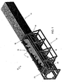
FIG. 1 is a perspective view of a loading assembly in accordance with the present invention, depicting a load bin of the loading assembly aligned with an opening of a transport container. -
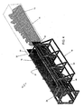
FIG. 2 is a perspective view of the loading assembly ofFIG. 1 , depicting the load bin fully extended into the container (in phantom) and a barrier assembly disposed adjacent to the opening of the container. -
FIG. 3 is a perspective view of the loading assembly ofFIG. 1 , depicting the load bin partially withdrawn from the container (in phantom) and having a gate of the bin open. -
FIG. 4 is a perspective view of the loading assembly ofFIG. 1 , depicting the load bin fully withdrawn from the container (in phantom). -
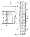
FIG. 5 is a front elevational view of the load bin of the loading assembly ofFIG. 1 , with the gate excluded for clarity. -
FIG. 6 is a side elevational view of the load bin of the loading assembly ofFIG. 1 . -
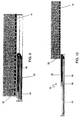
FIG. 7 is a front elevational view of the barrier assembly of the loading assembly ofFIG. 1 . -
FIG. 8 is a side elevational view of the barrier assembly of the loading assembly ofFIG. 1 . -
FIG. 9 is a side elevational view of the drive mechanism and load bin of the loading assembly ofFIG. 1 , depicting the load bin retracted. -
FIG. 10 is a side elevational view of the drive mechanism and load bin of the loading assembly ofFIG. 1 , depicting the load bin fully extended. -
FIG. 11 is an exploded perspective view of the drive mechanism of the loading assembly ofFIG. 1 . - Referring now to the drawings, and particularly to
FIG. 1 , there is shown aloading assembly 10 configured to loadbulk material 12, e.g., scrap metal, intotransport containers 14. The loading assembly includes asupport structure 16 and aload bin 18 sized to conform to the internal dimensions of the container. The load bin has an open top 21, allowing it to be top-loaded to facilitate efficient loading of bulk material. The assembly includes a drive mechanism 22 (FIG. 9 ) configured to urge the load bin into and out of the container. When fully inserted, the contents of the load bin are completely disposed within the container. The loading assembly further includes abarrier assembly 24 configured to keep the load confined within the container and agate 26 that allows the bulk material to exit the load bin upon retraction. In this manner, the container can be loaded to capacity with bulk material quickly and efficiently. -
FIGS. 1-4 depict sequential operation of theloading assembly 10, with thecontainer 14 in phantom for visibility. The loading assembly operates through several phases, including material loading (FIG. 1 ), transfer (FIG. 2 ), and retraction (FIGS. 3 and4 ), thereby loading the container to capacity in a single operation. During the loading phase, theload bin 18 is preferably disposed within thesupport structure 16, allowing the load bin to be top loaded, even while aligned with the container. The load bin is filled withbulk material 12 up to a desired level. For example, the load assembly can be used with both 20-ft and 40-ft containers. When loading a 20-ft container, thebarrier 24 can be positioned at a midpoint along the load bin, thereby defining in volume that conforms to the internal volume of a 20-ft container. When loading a 40-ft container, the barrier is positioned at anend wall 28 of the load bin. Operators can fill the load bin with bulk material via the open top 21, as desired. - Once loaded, the transfer phase can be initiated. In this phase, the
drive mechanism 22 urges theload bin 18 into thecontainer 14. This phase continues until the contents of the load bin are fully disposed within the container. When desired, the load bin can then be retracted, leaving thebulk material 12 within the container. As best seen inFIG. 3 , during the retraction phase, thegate 26 is unlocked, and thebarrier 24 remains positioned against anopen end 30 of the container. The drive mechanism retracts the load bin from the container until the bin is removed from the container (FIG. 4 ), at which point the container is free for transport. - With reference to
FIGS. 1 ,5 and 6 , theload bin 18 includes sidewalls 32, abottom wall 34, and theend wall 28 spaced from thegate 26. In the exemplary embodiment, the load bin is sized to conform to the internal dimensions of typical 20-ft. or 40-ft. transport containers. More particularly, the load bin has an external height (He) of about 2134mm (7 ft), an external width (Wc) of about 2261mm (7 ft., 5 in), and a length (L) of about 13512mm (44 ft., 4 in). The load bin has an internal height (Hj) of about 2082mm (6 ft. 10 in), an external width (Wi) of about 2234mm (7 ft., 4 in). The load bin also includesroller 36 along the bottom wall to aid in smooth movement of the bin along the container. Other embodiments are contemplated having a load bin sized to conform to containers of various other sizes, e.g., railroad cars, storage containers, and semi trailers. The load bin can be loaded to capacity easily with bulk material, and it can effectively hold bulk material having a high degree of variability in make-up. For example, the load bin can hold a single load of scrap steel having pieces varying size from as small as 0.025 mm x 25 mm x 0.635 mm (0.01 in. x 1 in. x 0.25 in.) up to and in excess of 1.52 m x 0.91 m x 0.3m (5 ft. x 3 ft. x 1 ft.). - To facilitate operation of the
loading assembly 10,interior surfaces 38 of theload bin 18 are relatively smooth, free of excessive ridges and grooves, such that the load bin can be retracted without having bulk material unduly catching the surface, particularly during retraction. In the exemplary embodiment, the walls of the load bin includesteel paneling 40 supported by reinforcingbeams 42 spaced along the length of the load bin. The interior surfaces are defined by the paneling of the walls of the load bin. Optionally, supplemental materials or coatings can be used for the interior surfaces to facilitate retraction of the load bin. For example, in other embodiments, the load bin can include rollers disposed along interior surfaces to facilitate loading of the container. - With reference now to
FIGS. 7 and 8 , thebarrier 24 includes a leadingwall 41 attached to abrace 43. The leading wall is configured to closely conform to the interior dimensions of the load bin and includes aforward projection 45 that aids in confining thebulk material 12 in front of the leading wall throughout operation of the loading assembly. In the exemplary embodiment, the leading wall has a height (Hf) of about 2033mm (6 ft., 8 in), while the overall height (Hb) of the barrier is about 2286mm (7 ft, 6 in). The upper portion of the barrier extends out the open top 20 of the load bin and is guided along thesupport structure 16. - As shown in
FIGS. 1-4 , thegate 26 of theload bin 18 includes twodoors 44 hinged to correspondingsidewalls 32 and a locking mechanism for securing the doors closed. During loading and transfer of the bulk material, the gate is configured to remain secure. Once the load bin is fully inserted into the container, the gate is unsecured, enabling the load to remain in the container upon withdrawal of the load bin. In the exemplary embodiment, the locking mechanism is released by remote activation initiated by the operator; however, various other approaches can be used, e.g., hydraulic or electric linkage to open, gravity to open, or spring loaded. Moreover, other approaches can be used for allowing the load to remain in the container upon removal of the bin. For example, various gate configurations can be used, such as, rolling track doors and horizontally hinged doors. Also, sacrificial doors can be used, e.g., in which the door is configured to remain in the container or to deteriorate or to be destroyed upon retraction of the load bin. In yet other embodiments, the load bin can be configured without a gate. Instead, material can be positioned to serve as a sacrificial end wall such that it remains in the bin during transfer and remains in the container upon removal of the load bin. For example, a large piece of scrap steel can be position near the open end in manner that retains the material within the bin during loading yet allows the load to remain within the container during retraction. In selected embodiments, the floor of the load bin can be configured to be movable relative to the side walls such that the floor can be displaced while within the container, allowing the load to remain in the container. - With reference now to
FIG. 2 , thesupport structure 16 is configured to promote stability of theload assembly 10 during all phases of operation. In the exemplary embodiment, the loading assembly is configured to transfer a load of in excess of approx. 26,300 kg (about 58,000 pounds). The support structure includesexternal framing 48 disposed about theload bin 18, side buttresses 50, and abase support 52. The load assembly can be disassembled for transportation, if desired. The support structure can be disassembled and housed within the load bin. The overall weight of the load assembly is less than 19,050kg (42,000 pounds), making it convenient for transport. The base support is positioned below the bottom wall 34 (FIG. 5 ) of the load bin and includes a plurality ofrollers 54 to facilitate longitudinal movement of the load bin. In the exemplary embodiment, the base support is integrated with a weight scale (not shown) to provide weight measurement of the load. Optionally, the base support can be configured to move in support of operation of the load assembly. For example, the load assembly can be configured to aid in aligning the load bin with the container, e.g., via movement of the base support, including lateral and vertical adjustments. Also, the base support can be configured to tilt and vibrate to facilitate in dispensing the load within the container. - With reference to
FIGS. 1-4 and9-11 , thedrive mechanism 22 is configured urge theload bin 18 into and out of thecontainer 14, through the transfer and retraction phases, in a timely manner. The drive is attached to thesupport structure 16 and the load bin and provides a cycle time through the transfer and retraction phases of less than about 8 minutes. The drive mechanism includes ahydraulic cylinder 56 and acable assembly 58 operatively connected to the load bin. The hydraulic cylinder includes apiston 60 disposed in acylinder housing 62. The cable assembly includes pulley blocks 64 disposed on opposite ends of asupport beam 66 withcabling 68 looped around the pulley blocks. - The
drive mechanism 22 is aligned between two guide beams 70 (FIG.11 ) below the bottom wall of theload bin 18. As best seen inFIGS. 9 and 10 , the hydraulic cylinder displaces the cable assembly and, in turn, the load bin. Thepiston 60 of the hydraulic cylinder can extend over 6096mm (20 feet) out thecylinder housing 62. The cable assembly can further displace the load bin, approximately 6096mm (20 feet). In the exemplary embodiment, a hydraulic drive mechanism is used; however, various other drive mechanisms can be used, e.g., electric, gas or diesel engine. Moreover, various other approaches can be used for translating the force from the drive mechanism in to movement of the load bin, e.g., piston, rack and pinion, belt drive, cable/drum, chain/sprocket, and gear reduction. - It should be appreciated from the foregoing that the present invention provides a loading assembly configured to load transport containers with bulk material quickly and efficiently. The assembly includes a load bin having a cross section conforming to an open end of a container and a drive mechanism configured urge the load bin into and out of the container. When fully inserted, the contents of the load bin are completely disposed within the container. The loading assembly further includes a barrier configured to keep the load confined within the container, while the load bin opens to allow the load to remain within the container upon retraction, In this manner, the-container can be filled to capacity in a single operation.
- Although the invention has been disclosed in detail with reference only to the exemplary embodiments, those skilled in the art will appreciate that various other embodiments can be provided without departing from the scope of the invention. Accordingly, the invention is defined only by the claims set forth below.
Claims (11)
- A bulk material loading assembly (10) configured to load a transport container (14) having an open end (30) with a load of non-uniformly shaped bulk materials, comprising:a load bin (18) having a cross section conforming to an open end (30) of a transport container (14) such that the load bin (18) can be inserted therethrough, the load bin (18) defining a top opening (21) for receiving a load (12) of non-uniformly shaped bulk materials, the load bin (18) defining a volume configured to hold a load (12) of non-uniformly shaped bulk materials of sufficient size to fill the container (14) to capacity in a single operation;a support structure (16) for supporting the load bin (18) and being arranged, in use, to be substantially stationary;a drive mechanism (22) configured to urge the load bin into and out of the container to enable displacement of the load (12) into the container (14) through the open end (30) thereof and to retract the load bin (18) from the container (14); anda barrier assembly (24) configured to confine the contents of the load bin (18) in the container while the load bin (18) is retracted, allowing the contents of the load bin (18) to remain within the container (14) upon removal of the load bin (18).
- A loading assembly as claimed in claim 1 wherein the load bin (18) includes a floor (34), two side walls (32), an endwall (28) and a movable front wall (26).
- A loading assembly as claimed in claim 1 or 2, wherein the barrier assembly (24) is arranged to be positioned in the load bin (18), prior to loading, to conform the internal volume of the load bin to prescribed container sizes.
- A loading assembly as claimed in any one of the preceding claims, wherein the load bin is configured to hold a load in excess of 9979 kilograms (22,000 pounds).
- A loading assembly as claimed in any one of the preceding claims 2 to 4, wherein the front wall (26) the load bin (18) further includes a door (44) configured to be movable to an open position, to allow the load (12) to exit the load bin upon retraction thereof relative to the container (14), thereby allowing the load to remain within the container.
- A loading assembly as claimed in any one of the preceding claims when dependent on claim 2, wherein the movable front wall (26) is configured to remain within the container upon retraction of the load bin (18) relative to the container (14).
- A loading assembly as defined in claim 1, wherein the drive mechanism (22) includes a hydraulic cylinder (56) and a cable assembly (58) operatively connected to the load bin (18).
- A loading assembly as claimed in any of the preceding claims, wherein the support structure (16) includes external framing (48) disposed about the load bin.
- A loading assembly as claimed in any of the preceding claims, wherein the barrier assembly (24) further includes a leading wall (41) attached to a brace (43).
- A loading assembly as claimed in any one of the preceding claims, wherein the drive assembly (22) is arranged to retract the load bin (18) within the support structure (16) during separation of the load bin from the transport container (14).
- A method of loading a transport container (14), comprising:positioning a loading assembly (10) as claimed in any of the preceding claims and a container (14) relative to one another such that the loading assembly (10) is adjacent to an open end (30) of the container (14);inserting a load of non-uniformly shaped bulk materials in the load bin via the top opening;inserting the load bin (18) into the container (14) through the open end (30) thereof until the load (12) is fully disposed within the container (14);positioning the barrier assembly (24) adjacent to the open end (30) of the container (14); andretracting the load bin (18), with the barrier assembly (24) in place, such that the load (12) remains within the container (14).
Priority Applications (3)
| Application Number | Priority Date | Filing Date | Title |
|---|---|---|---|
| SI200531040T SI1799599T2 (en) | 2004-10-12 | 2005-10-11 | Loading assembly for transport containers |
| PL05809786T PL1799599T5 (en) | 2004-10-12 | 2005-10-11 | Loading assembly for transport containers |
| CY20101100579T CY1111231T1 (en) | 2004-10-12 | 2010-06-24 | LOADING FOR SHIPPING CONTAINERS |
Applications Claiming Priority (2)
| Application Number | Priority Date | Filing Date | Title |
|---|---|---|---|
| US10/964,384 US7172382B2 (en) | 2004-10-12 | 2004-10-12 | Loading assembly for transport containers, and related method of use |
| PCT/US2005/036512 WO2006044371A1 (en) | 2004-10-12 | 2005-10-11 | Loading assembly for transport containers |
Publications (3)
| Publication Number | Publication Date |
|---|---|
| EP1799599A1 EP1799599A1 (en) | 2007-06-27 |
| EP1799599B1 EP1799599B1 (en) | 2010-03-24 |
| EP1799599B2 true EP1799599B2 (en) | 2017-03-15 |
Family
ID=35789063
Family Applications (1)
| Application Number | Title | Priority Date | Filing Date |
|---|---|---|---|
| EP05809786.6A Active EP1799599B2 (en) | 2004-10-12 | 2005-10-11 | Loading assembly for transport containers |
Country Status (17)
| Country | Link |
|---|---|
| US (1) | US7172382B2 (en) |
| EP (1) | EP1799599B2 (en) |
| JP (2) | JP5511137B2 (en) |
| KR (2) | KR101308240B1 (en) |
| AT (1) | ATE461895T2 (en) |
| AU (1) | AU2005295868B2 (en) |
| CA (1) | CA2590327C (en) |
| CY (1) | CY1111231T1 (en) |
| DE (1) | DE602005020164D1 (en) |
| DK (1) | DK1799599T4 (en) |
| ES (1) | ES2344656T5 (en) |
| HK (1) | HK1104518A1 (en) |
| PL (1) | PL1799599T5 (en) |
| PT (1) | PT1799599E (en) |
| SI (1) | SI1799599T2 (en) |
| WO (1) | WO2006044371A1 (en) |
| ZA (1) | ZA200702248B (en) |
Families Citing this family (27)
| Publication number | Priority date | Publication date | Assignee | Title |
|---|---|---|---|---|
| US7588406B2 (en) * | 2004-10-12 | 2009-09-15 | Fastek, Llc | Loading assembly for transport containers, and related method of use |
| US20070065260A1 (en) * | 2005-08-23 | 2007-03-22 | Chapman Don K | Trailer tipper backstop and safety hoop |
| US20090317218A1 (en) * | 2005-08-23 | 2009-12-24 | Phelps Industries, Inc. | Container tilter |
| US7866932B1 (en) | 2007-03-02 | 2011-01-11 | Sp Industries, Inc. | Container loader with container wall protector and method for loading a container |
| US7837428B2 (en) | 2007-03-05 | 2010-11-23 | SA Recycling LLC | Methods and apparatuses for freight container loading |
| US8668425B2 (en) | 2007-03-05 | 2014-03-11 | SA Recycling LLC | Methods and apparatus for freight container loading |
| EP2173648A4 (en) * | 2007-07-27 | 2012-11-21 | Container Stuffers Llc | Cargo loader |
| GB2451631A (en) * | 2007-08-04 | 2009-02-11 | Dunn Brothers | Container loading apparatus |
| TWM333876U (en) * | 2007-09-21 | 2008-06-11 | Jer-Yuan Jang | Device of auxiliary bathing tool |
| US9056731B1 (en) | 2008-06-13 | 2015-06-16 | Advanced Steel Recovery, Llc | Container packer system and method |
| US7744330B2 (en) * | 2008-06-13 | 2010-06-29 | Blue Tee Corporation | Container packer system and method |
| JP5107160B2 (en) * | 2008-07-01 | 2012-12-26 | 株式会社アイ・エイチ・アイ・アムテック | Conveying apparatus and conveying method |
| FI124703B (en) * | 2009-09-29 | 2014-12-15 | Jouni Järvensivu | Method and equipment for filling the container |
| US8784031B2 (en) | 2010-01-04 | 2014-07-22 | Container Stuffers, Llc | Cargo loader |
| US8662813B2 (en) * | 2010-01-22 | 2014-03-04 | Greg R. Bushong | Loading apparatus for transport container |
| US9120632B2 (en) * | 2010-10-27 | 2015-09-01 | Venture Metals Machinery, Llc | Scrap metal loader apparatus and method of operation |
| AU2012218238A1 (en) | 2011-02-17 | 2013-09-19 | A Ward Attachments Limited | Container loader |
| US9738464B1 (en) * | 2012-10-18 | 2017-08-22 | Scott Sakajian | System and method for protecting containers from damage during loading |
| CN103253611B (en) * | 2013-05-09 | 2015-09-30 | 洛阳理工学院 | A kind of hydaulic lift platform with vertical equity mobile device |
| FI125768B (en) * | 2014-03-17 | 2016-02-15 | Actiw Oy | Arrangement for loading the load compartment |
| USD817147S1 (en) * | 2017-02-15 | 2018-05-08 | Bluewater Resources LLC | Transport container lock |
| USD811197S1 (en) * | 2017-02-15 | 2018-02-27 | Bluewater Resources LLC | Transport-container lock |
| USD811196S1 (en) * | 2017-02-15 | 2018-02-27 | Bluewater Resources LLC | Transport-container lock |
| CN107555194B (en) * | 2017-07-25 | 2019-08-27 | 温州盛淼工业设计有限公司 | A kind of tire boxing apparatus |
| FI128153B (en) * | 2018-06-29 | 2019-11-15 | Actiw Oy | Loading frame, equipment and method for loading products |
| US11597588B2 (en) * | 2020-05-08 | 2023-03-07 | Workshops for Warriors | Modular structure systems |
| CN111620005A (en) * | 2020-06-19 | 2020-09-04 | 北京恒创源科技有限公司 | Classified garbage throwing and conveying system structure for high-rise building |
Citations (6)
| Publication number | Priority date | Publication date | Assignee | Title |
|---|---|---|---|---|
| US3809264A (en) † | 1972-05-17 | 1974-05-07 | Container Bins Inc | Method of loading cargo containers |
| US4055265A (en) † | 1976-09-10 | 1977-10-25 | Eisenman Leonard J | Bulk bed |
| DE2720028A1 (en) † | 1977-05-04 | 1978-11-09 | Abdurrahman Karabulut | Palletised stack transfer mechanism for freight container - has roller equipped supporting rails joined by thruster yoke on truck |
| US4537554A (en) † | 1983-01-14 | 1985-08-27 | The United States Of America As Represented By The Administrator Of The National Aeronautics And Space Administration | Shuttle car loading system |
| JPS61221017A (en) † | 1985-03-25 | 1986-10-01 | Nissan Motor Co Ltd | Cargo loading device |
| EP1221398A1 (en) † | 2001-01-08 | 2002-07-10 | Cleri Industrie SARL | Pusher plate for unloading a vehicle with a horizontal container |
Family Cites Families (57)
| Publication number | Priority date | Publication date | Assignee | Title |
|---|---|---|---|---|
| US3273728A (en) * | 1966-09-20 | Kelso rear unloading box | ||
| US2478658A (en) * | 1946-03-08 | 1949-08-09 | Howard F Cook | Mechanism for transferring a body from a trailer chassis to a truck chassis and viceversa |
| US2856086A (en) * | 1956-10-01 | 1958-10-14 | Valentino L Balbi | Refuse truck |
| US2849129A (en) * | 1956-12-03 | 1958-08-26 | James R Likens | Load transferring apparatus |
| US3040914A (en) * | 1959-05-12 | 1962-06-26 | Clark Equipment Co | Method and means for handling freight |
| US3175708A (en) * | 1963-01-10 | 1965-03-30 | Fruehauf Trailer Co | Support for hydraulic cylinder |
| US3186566A (en) * | 1963-07-10 | 1965-06-01 | Procter & Gamble | Apparatus for loading and unloading vehicles |
| US3220586A (en) * | 1963-08-26 | 1965-11-30 | Leach Corp | Refuse collecting and transporting vehicle |
| US3252602A (en) * | 1964-03-05 | 1966-05-24 | Samuel V Bowles | Refuse handling and transporting apparatus |
| US3456825A (en) * | 1968-02-21 | 1969-07-22 | Ralph D Lacoe Jr | Slide editor and storage apparatus |
| US3616957A (en) * | 1969-05-15 | 1971-11-02 | Lawrence Alfred Patton | Container stuffing sleeve |
| US3667635A (en) * | 1969-07-14 | 1972-06-06 | Hackney & Sons Inc J A | Combined truck body and wheeled rack and method of loading and unloading a van |
| US3688926A (en) * | 1970-05-18 | 1972-09-05 | William L Stefanelli | Cargo handling system |
| US3727777A (en) * | 1971-05-07 | 1973-04-17 | D Hanson | Loader for trucks |
| DE2205505C3 (en) * | 1972-02-05 | 1975-07-03 | Foerdertechnische Forschungsgesellschaft Mbh, 2000 Hamburg | Device for loading containers with piece goods, preferably loaded pallets |
| JPS5233864B2 (en) * | 1972-04-12 | 1977-08-31 | ||
| US3815764A (en) * | 1972-06-21 | 1974-06-11 | East Coast Equipment Corp | Load body with load compacting and ejecting blade |
| US4020958A (en) | 1972-12-06 | 1977-05-03 | Wheeler Robert R | Bulk material container loading and system |
| US4016991A (en) * | 1974-04-10 | 1977-04-12 | Oldford William G | Railway loading and unloading system |
| US3952887A (en) * | 1974-04-16 | 1976-04-27 | Lutz David E | Vehicle loading and unloading apparatus |
| US3938678A (en) | 1974-09-18 | 1976-02-17 | Kern Ruy E | Cargo transport system |
| US3966075A (en) * | 1975-01-10 | 1976-06-29 | Schultz Gerhard L | Cargo container |
| US4102262A (en) | 1975-12-17 | 1978-07-25 | Carrier Corporation | Apparatus for loading refuse into containers |
| US4011957A (en) * | 1976-01-16 | 1977-03-15 | Caterpillar Tractor Co. | Folding ejector linkage for material handling machinery |
| US4044899A (en) * | 1976-06-07 | 1977-08-30 | Robert J. Bruce | Horizontally discharging semi-trailer |
| US4260317A (en) * | 1978-11-01 | 1981-04-07 | Diesel Equipment Limited | Telescopic body with ejection bulkhead |
| JPS5899134U (en) * | 1981-12-26 | 1983-07-06 | 新明和工業株式会社 | Truck load discharge device |
| US4522556A (en) * | 1982-09-29 | 1985-06-11 | Star Textile Research, Inc. | Method and device for packaging and shipping high-loft batting |
| JPS5981638U (en) * | 1982-11-25 | 1984-06-01 | 林 光夫 | Truck loading platform for construction work |
| US4645406A (en) | 1984-07-17 | 1987-02-24 | Cooper Augustus J | Container loader and transport assembly |
| US5054987A (en) * | 1985-05-29 | 1991-10-08 | Valcomatic Systems, Inc. | Load transfer device |
| US5040938A (en) * | 1986-12-18 | 1991-08-20 | G & G Intellectual Properties, Inc. | Loading and transporting system |
| US4919582A (en) * | 1988-04-14 | 1990-04-24 | Greenbrier Intermodal, Inc. | Method and apparatus for loading automobiles into a cargo container |
| US4923356A (en) * | 1988-05-03 | 1990-05-08 | Foster Raymond K | Apparatus for collecting and compacting garbage and then loading it into a road vehicle |
| US5026228A (en) | 1988-06-06 | 1991-06-25 | Mansfield P Michael | Truck trailer with hydraulic cargo container positioning mechanism |
| JP2620707B2 (en) * | 1988-08-04 | 1997-06-18 | 武 林 | Lift-spoke type cargo handling equipment |
| KR920001714B1 (en) | 1989-08-07 | 1992-02-24 | 서동진 | Pallet & pallet united container |
| KR910011650A (en) * | 1989-11-27 | 1991-08-07 | 김형돈 | Wide magnetic field water treatment method by heterogeneous magnetic field band combination |
| US5026229A (en) * | 1989-12-15 | 1991-06-25 | Trinity Industries, Inc. | Collapsible hitch |
| US5193968A (en) * | 1990-02-15 | 1993-03-16 | Hicks W Glenn | Pull trailer dump truck |
| US5186596A (en) * | 1991-10-04 | 1993-02-16 | Paul Boucher | Loading and unloading apparatus |
| JPH0733260A (en) * | 1993-06-30 | 1995-02-03 | Kouun Kouzou Kaizen Sokushin Zaidan | Automatic vanning system and van loader used for it |
| US5577873A (en) | 1993-11-30 | 1996-11-26 | Kao Corporation | Method and apparatus for stowing a load |
| US5564767A (en) | 1994-08-23 | 1996-10-15 | Strepek; John E. | Motorized extendible drawer apparatus for a vehicle |
| US5527147A (en) * | 1994-10-31 | 1996-06-18 | Altamont, Inc. | Waste handling method and apparatus for transferring waste from collection vehicles to transfer trailers |
| CA2150606C (en) * | 1995-04-25 | 2003-12-30 | Jerome R. Lesmeister | Container with expandable side walls and method |
| JPH10291583A (en) * | 1997-04-18 | 1998-11-04 | Idemitsu Petrochem Co Ltd | Transport container |
| JP3814375B2 (en) * | 1997-06-09 | 2006-08-30 | 出光エンジニアリング株式会社 | Cargo input method |
| US6138557A (en) | 1999-02-23 | 2000-10-31 | Marathon Equipment Company | Method and apparatus for measuring the length of a waste log and/or weight of waste log while compacting and transferring the waste log for transport |
| JP2000281175A (en) * | 2000-01-01 | 2000-10-10 | Idemitsu Petrochem Co Ltd | Bag body for transport container |
| JP4536860B2 (en) * | 2000-02-17 | 2010-09-01 | 出光興産株式会社 | Shipping container |
| US6312206B1 (en) | 2000-02-22 | 2001-11-06 | Planters Cotton Oil Mill, Inc. | Method and apparatus for loading bulk materials |
| JP4191872B2 (en) * | 2000-03-15 | 2008-12-03 | 出光興産株式会社 | Transport container bag |
| US6808356B2 (en) * | 2000-12-28 | 2004-10-26 | Toyota Steel Center Co., Ltd. | Device for carrying article into and from container, method for introducing and discharging article into and from container, and pallet for carrying article |
| BR0106400B1 (en) | 2001-09-13 | 2009-08-11 | flexible bulk cargo liner applicable inside cargo containers, and installation process for flexible bulk cargo liner installation within cargo containers. | |
| AUPS125102A0 (en) | 2002-03-21 | 2002-04-18 | Byrne Trailer Manufacturing (Wagga Wagga) Pty Limited | Improved compactor system |
| AT5703U3 (en) * | 2002-07-23 | 2003-09-25 | Plasser Bahnbaumasch Franz | STORAGE TROLLEY WITH A KEY DEVICE |
-
2004
- 2004-10-12 US US10/964,384 patent/US7172382B2/en active Active
-
2005
- 2005-10-11 SI SI200531040T patent/SI1799599T2/en unknown
- 2005-10-11 AT AT05809786T patent/ATE461895T2/en active
- 2005-10-11 CA CA2590327A patent/CA2590327C/en active Active
- 2005-10-11 KR KR1020077010718A patent/KR101308240B1/en active IP Right Review Request
- 2005-10-11 AU AU2005295868A patent/AU2005295868B2/en active Active
- 2005-10-11 ES ES05809786.6T patent/ES2344656T5/en active Active
- 2005-10-11 WO PCT/US2005/036512 patent/WO2006044371A1/en active Application Filing
- 2005-10-11 DK DK05809786.6T patent/DK1799599T4/en active
- 2005-10-11 PT PT05809786T patent/PT1799599E/en unknown
- 2005-10-11 JP JP2007536801A patent/JP5511137B2/en active Active
- 2005-10-11 DE DE602005020164T patent/DE602005020164D1/en active Active
- 2005-10-11 EP EP05809786.6A patent/EP1799599B2/en active Active
- 2005-10-11 PL PL05809786T patent/PL1799599T5/en unknown
- 2005-10-11 KR KR1020137014232A patent/KR20130079625A/en not_active Application Discontinuation
-
2007
- 2007-03-19 ZA ZA200702248A patent/ZA200702248B/en unknown
- 2007-11-27 HK HK07112943.6A patent/HK1104518A1/en active IP Right Maintenance
-
2010
- 2010-06-24 CY CY20101100579T patent/CY1111231T1/en unknown
-
2013
- 2013-04-17 JP JP2013086656A patent/JP5856099B2/en not_active Expired - Fee Related
Patent Citations (6)
| Publication number | Priority date | Publication date | Assignee | Title |
|---|---|---|---|---|
| US3809264A (en) † | 1972-05-17 | 1974-05-07 | Container Bins Inc | Method of loading cargo containers |
| US4055265A (en) † | 1976-09-10 | 1977-10-25 | Eisenman Leonard J | Bulk bed |
| DE2720028A1 (en) † | 1977-05-04 | 1978-11-09 | Abdurrahman Karabulut | Palletised stack transfer mechanism for freight container - has roller equipped supporting rails joined by thruster yoke on truck |
| US4537554A (en) † | 1983-01-14 | 1985-08-27 | The United States Of America As Represented By The Administrator Of The National Aeronautics And Space Administration | Shuttle car loading system |
| JPS61221017A (en) † | 1985-03-25 | 1986-10-01 | Nissan Motor Co Ltd | Cargo loading device |
| EP1221398A1 (en) † | 2001-01-08 | 2002-07-10 | Cleri Industrie SARL | Pusher plate for unloading a vehicle with a horizontal container |
Also Published As
| Publication number | Publication date |
|---|---|
| AU2005295868A1 (en) | 2006-04-27 |
| JP5511137B2 (en) | 2014-06-04 |
| DK1799599T3 (en) | 2010-07-19 |
| KR20070085302A (en) | 2007-08-27 |
| KR101308240B1 (en) | 2013-09-13 |
| ZA200702248B (en) | 2008-05-28 |
| WO2006044371A1 (en) | 2006-04-27 |
| DK1799599T4 (en) | 2017-07-10 |
| US20060078410A1 (en) | 2006-04-13 |
| SI1799599T2 (en) | 2017-06-30 |
| JP2008515745A (en) | 2008-05-15 |
| CA2590327C (en) | 2013-07-16 |
| JP2013173619A (en) | 2013-09-05 |
| PT1799599E (en) | 2010-06-30 |
| US7172382B2 (en) | 2007-02-06 |
| ATE461895T2 (en) | 2010-04-15 |
| JP5856099B2 (en) | 2016-02-09 |
| AU2005295868B2 (en) | 2011-07-21 |
| ES2344656T3 (en) | 2010-09-02 |
| PL1799599T5 (en) | 2017-10-31 |
| ES2344656T5 (en) | 2017-08-02 |
| CY1111231T1 (en) | 2015-06-11 |
| HK1104518A1 (en) | 2008-01-18 |
| EP1799599A1 (en) | 2007-06-27 |
| KR20130079625A (en) | 2013-07-10 |
| CA2590327A1 (en) | 2006-04-27 |
| DE602005020164D1 (en) | 2010-05-06 |
| EP1799599B1 (en) | 2010-03-24 |
| PL1799599T3 (en) | 2010-08-31 |
| SI1799599T1 (en) | 2010-08-31 |
Similar Documents
| Publication | Publication Date | Title |
|---|---|---|
| EP1799599B2 (en) | Loading assembly for transport containers | |
| US7588406B2 (en) | Loading assembly for transport containers, and related method of use | |
| US8690512B2 (en) | Apparatus for freight container loading | |
| US10954086B1 (en) | Container packer system and method | |
| KR101217098B1 (en) | Hopper type transportation container for through transit | |
| CA3023011A1 (en) | Method of storing and moving proppant for use at a well site | |
| EP2233425A2 (en) | A system and an unloading device for unloading material | |
| US20130183134A1 (en) | Methods and apparatus for freight container loading | |
| KR101398421B1 (en) | Hopper type transportation container for through transit | |
| EP2440478B1 (en) | Transport container | |
| CN213650645U (en) | ISO standard container | |
| JP3743776B2 (en) | Container deferred structure | |
| JP2584838Y2 (en) | Floor for warehouse or transportation equipment | |
| KR100836320B1 (en) | Up/down device of tail gate in commercial truck | |
| FI124703B (en) | Method and equipment for filling the container | |
| EP3006375A1 (en) | A method for transporting demountable platforms in an articulated transport vehicle, and a series of demountable platforms | |
| US20150144639A1 (en) | Mud skid | |
| JP2004149138A (en) | Container with loading apparatus |
Legal Events
| Date | Code | Title | Description |
|---|---|---|---|
| PUAI | Public reference made under article 153(3) epc to a published international application that has entered the european phase |
Free format text: ORIGINAL CODE: 0009012 |
|
| 17P | Request for examination filed |
Effective date: 20070316 |
|
| AK | Designated contracting states |
Kind code of ref document: A1 Designated state(s): AT BE BG CH CY CZ DE DK EE ES FI FR GB GR HU IE IS IT LI LT LU LV MC NL PL PT RO SE SI SK TR |
|
| DAX | Request for extension of the european patent (deleted) | ||
| REG | Reference to a national code |
Ref country code: HK Ref legal event code: DE Ref document number: 1104518 Country of ref document: HK |
|
| 17Q | First examination report despatched |
Effective date: 20080310 |
|
| GRAP | Despatch of communication of intention to grant a patent |
Free format text: ORIGINAL CODE: EPIDOSNIGR1 |
|
| GRAS | Grant fee paid |
Free format text: ORIGINAL CODE: EPIDOSNIGR3 |
|
| GRAA | (expected) grant |
Free format text: ORIGINAL CODE: 0009210 |
|
| AK | Designated contracting states |
Kind code of ref document: B1 Designated state(s): AT BE BG CH CY CZ DE DK EE ES FI FR GB GR HU IE IS IT LI LT LU LV MC NL PL PT RO SE SI SK TR |
|
| REG | Reference to a national code |
Ref country code: GB Ref legal event code: FG4D |
|
| REG | Reference to a national code |
Ref country code: CH Ref legal event code: EP |
|
| REG | Reference to a national code |
Ref country code: IE Ref legal event code: FG4D |
|
| REF | Corresponds to: |
Ref document number: 602005020164 Country of ref document: DE Date of ref document: 20100506 Kind code of ref document: P |
|
| REG | Reference to a national code |
Ref country code: RO Ref legal event code: EPE |
|
| REG | Reference to a national code |
Ref country code: PT Ref legal event code: SC4A Free format text: AVAILABILITY OF NATIONAL TRANSLATION Effective date: 20100624 Ref country code: CH Ref legal event code: NV Representative=s name: AMMANN PATENTANWAELTE AG BERN |
|
| REG | Reference to a national code |
Ref country code: NL Ref legal event code: T3 |
|
| REG | Reference to a national code |
Ref country code: DK Ref legal event code: T3 |
|
| REG | Reference to a national code |
Ref country code: SE Ref legal event code: TRGR |
|
| REG | Reference to a national code |
Ref country code: GR Ref legal event code: EP Ref document number: 20100401482 Country of ref document: GR |
|
| REG | Reference to a national code |
Ref country code: PL Ref legal event code: T3 |
|
| REG | Reference to a national code |
Ref country code: ES Ref legal event code: FG2A Ref document number: 2344656 Country of ref document: ES Kind code of ref document: T3 |
|
| REG | Reference to a national code |
Ref country code: SK Ref legal event code: T3 Ref document number: E 7409 Country of ref document: SK |
|
| REG | Reference to a national code |
Ref country code: HK Ref legal event code: GR Ref document number: 1104518 Country of ref document: HK |
|
| PG25 | Lapsed in a contracting state [announced via postgrant information from national office to epo] |
Ref country code: IS Free format text: LAPSE BECAUSE OF FAILURE TO SUBMIT A TRANSLATION OF THE DESCRIPTION OR TO PAY THE FEE WITHIN THE PRESCRIBED TIME-LIMIT Effective date: 20100724 |
|
| PLBI | Opposition filed |
Free format text: ORIGINAL CODE: 0009260 |
|
| 26 | Opposition filed |
Opponent name: JAERVENSIVU, JOUNI Effective date: 20101221 |
|
| REG | Reference to a national code |
Ref country code: HU Ref legal event code: AG4A Ref document number: E008930 Country of ref document: HU |
|
| PLAX | Notice of opposition and request to file observation + time limit sent |
Free format text: ORIGINAL CODE: EPIDOSNOBS2 |
|
| REG | Reference to a national code |
Ref country code: DK Ref legal event code: EBP |
|
| PG25 | Lapsed in a contracting state [announced via postgrant information from national office to epo] |
Ref country code: MC Free format text: LAPSE BECAUSE OF NON-PAYMENT OF DUE FEES Effective date: 20101031 |
|
| REG | Reference to a national code |
Ref country code: EE Ref legal event code: MM4A Ref document number: E004515 Country of ref document: EE Effective date: 20101031 |
|
| PLAF | Information modified related to communication of a notice of opposition and request to file observations + time limit |
Free format text: ORIGINAL CODE: EPIDOSCOBS2 |
|
| PG25 | Lapsed in a contracting state [announced via postgrant information from national office to epo] |
Ref country code: EE Free format text: LAPSE BECAUSE OF NON-PAYMENT OF DUE FEES Effective date: 20101031 |
|
| PG25 | Lapsed in a contracting state [announced via postgrant information from national office to epo] |
Ref country code: FI Free format text: LAPSE BECAUSE OF NON-PAYMENT OF DUE FEES Effective date: 20101011 |
|
| PGRI | Patent reinstated in contracting state [announced from national office to epo] |
Ref country code: FI Effective date: 20110610 |
|
| PG25 | Lapsed in a contracting state [announced via postgrant information from national office to epo] |
Ref country code: DK Free format text: LAPSE BECAUSE OF NON-PAYMENT OF DUE FEES Effective date: 20101031 |
|
| PLBB | Reply of patent proprietor to notice(s) of opposition received |
Free format text: ORIGINAL CODE: EPIDOSNOBS3 |
|
| REG | Reference to a national code |
Ref country code: DK Ref legal event code: EGE |
|
| APAH | Appeal reference modified |
Free format text: ORIGINAL CODE: EPIDOSCREFNO |
|
| APBM | Appeal reference recorded |
Free format text: ORIGINAL CODE: EPIDOSNREFNO |
|
| APBP | Date of receipt of notice of appeal recorded |
Free format text: ORIGINAL CODE: EPIDOSNNOA2O |
|
| APBM | Appeal reference recorded |
Free format text: ORIGINAL CODE: EPIDOSNREFNO |
|
| APBP | Date of receipt of notice of appeal recorded |
Free format text: ORIGINAL CODE: EPIDOSNNOA2O |
|
| APBQ | Date of receipt of statement of grounds of appeal recorded |
Free format text: ORIGINAL CODE: EPIDOSNNOA3O |
|
| PGFP | Annual fee paid to national office [announced via postgrant information from national office to epo] |
Ref country code: SE Payment date: 20121011 Year of fee payment: 8 |
|
| PGFP | Annual fee paid to national office [announced via postgrant information from national office to epo] |
Ref country code: FI Payment date: 20131010 Year of fee payment: 9 |
|
| PG25 | Lapsed in a contracting state [announced via postgrant information from national office to epo] |
Ref country code: SE Free format text: LAPSE BECAUSE OF NON-PAYMENT OF DUE FEES Effective date: 20101012 |
|
| PLAB | Opposition data, opponent's data or that of the opponent's representative modified |
Free format text: ORIGINAL CODE: 0009299OPPO |
|
| R26 | Opposition filed (corrected) |
Opponent name: JAERVENSIVU, JOUNI Effective date: 20101221 |
|
| PG25 | Lapsed in a contracting state [announced via postgrant information from national office to epo] |
Ref country code: FI Free format text: LAPSE BECAUSE OF NON-PAYMENT OF DUE FEES Effective date: 20141031 |
|
| APBU | Appeal procedure closed |
Free format text: ORIGINAL CODE: EPIDOSNNOA9O |
|
| REG | Reference to a national code |
Ref country code: FR Ref legal event code: PLFP Year of fee payment: 12 |
|
| PUAH | Patent maintained in amended form |
Free format text: ORIGINAL CODE: 0009272 |
|
| STAA | Information on the status of an ep patent application or granted ep patent |
Free format text: STATUS: PATENT MAINTAINED AS AMENDED |
|
| 27A | Patent maintained in amended form |
Effective date: 20170315 |
|
| AK | Designated contracting states |
Kind code of ref document: B2 Designated state(s): AT BE BG CH CY CZ DE DK EE ES FI FR GB GR HU IE IS IT LI LT LU LV MC NL PL PT RO SE SI SK TR |
|
| REG | Reference to a national code |
Ref country code: CH Ref legal event code: AELC Ref country code: DE Ref legal event code: R102 Ref document number: 602005020164 Country of ref document: DE |
|
| REG | Reference to a national code |
Ref country code: CH Ref legal event code: PCOW Free format text: NEW ADDRESS: C/O ADVANCED STEEL RECOVERY 8616 CHERRY AVENUE, FONTANA CALIFORNIA 92335 (US) |
|
| REG | Reference to a national code |
Ref country code: DE Ref legal event code: R082 Ref document number: 602005020164 Country of ref document: DE Representative=s name: LIPPERT STACHOW PATENTANWAELTE RECHTSANWAELTE , DE |
|
| REG | Reference to a national code |
Ref country code: NL Ref legal event code: FP |
|
| REG | Reference to a national code |
Ref country code: DK Ref legal event code: T4 Effective date: 20170704 |
|
| REG | Reference to a national code |
Ref country code: HK Ref legal event code: AM43 Ref document number: 1104518 Country of ref document: HK |
|
| REG | Reference to a national code |
Ref country code: ES Ref legal event code: DC2A Ref document number: 2344656 Country of ref document: ES Kind code of ref document: T5 Effective date: 20170802 |
|
| REG | Reference to a national code |
Ref country code: SI Ref legal event code: SP73 Owner name: FRANKEL, NATHAN; US Effective date: 20170727 |
|
| REG | Reference to a national code |
Ref country code: FR Ref legal event code: PLFP Year of fee payment: 13 |
|
| REG | Reference to a national code |
Ref country code: GR Ref legal event code: EP Ref document number: 20170401600 Country of ref document: GR Effective date: 20171023 |
|
| REG | Reference to a national code |
Ref country code: FR Ref legal event code: CA Effective date: 20171013 |
|
| REG | Reference to a national code |
Ref country code: SK Ref legal event code: TE4A Ref document number: E 7409 Country of ref document: SK Owner name: FRANKEL NATHAN, FONTANA, CALIFORNIA, US Effective date: 20180516 |
|
| REG | Reference to a national code |
Ref country code: SK Ref legal event code: T5 Ref document number: E 7409 Country of ref document: SK |
|
| REG | Reference to a national code |
Ref country code: FR Ref legal event code: PLFP Year of fee payment: 14 |
|
| REG | Reference to a national code |
Ref country code: LU Ref legal event code: PD Owner name: ADVANCED STEEL RECOVERY, LLC; US Free format text: FORMER OWNER: FRANKEL, NATHAN Effective date: 20221020 |
|
| REG | Reference to a national code |
Ref country code: GB Ref legal event code: 732E Free format text: REGISTERED BETWEEN 20221013 AND 20221019 |
|
| REG | Reference to a national code |
Ref country code: BE Ref legal event code: PD Owner name: ADVANCED STEEL RECOVERY, LLC; US Free format text: DETAILS ASSIGNMENT: CHANGE OF OWNER(S), ASSIGNMENT; FORMER OWNER NAME: FRANKEL, NATHAN Effective date: 20221017 |
|
| REG | Reference to a national code |
Ref country code: CH Ref legal event code: PK Free format text: BERICHTIGUNGEN |
|
| REG | Reference to a national code |
Ref country code: HU Ref legal event code: GB9C Owner name: ADVANCED STEEL RECOVERY, LLC, US Free format text: FORMER OWNER(S): FRANKEL, NATHAN, US; FRANKEL, NATHAN, US Ref country code: HU Ref legal event code: FH1C Free format text: FORMER REPRESENTATIVE(S): FARKAS TAMAS, DANUBIA SZABADALMI ES JOGI IRODA KFT, HU Representative=s name: DANUBIA SZABADALMI ES JOGI IRODA KFT., HU |
|
| REG | Reference to a national code |
Ref country code: NL Ref legal event code: PD Owner name: ADVANCED STEEL RECOVERY, LLC; US Free format text: DETAILS ASSIGNMENT: CHANGE OF OWNER(S), ASSIGNMENT; FORMER OWNER NAME: FRANKEL, NATHAN Effective date: 20230303 |
|
| REG | Reference to a national code |
Ref country code: ES Ref legal event code: PC2A Owner name: ADVANCED STEEL RECOVERY, LLC Effective date: 20230317 |
|
| REG | Reference to a national code |
Ref country code: SK Ref legal event code: PC4A Ref document number: E 7409 Country of ref document: SK Owner name: ADVANCED STEEL RECOVERY, LLC, FONTANA, CALIFOR, US Free format text: FORMER OWNER: FRANKEL NATHAN, FONTANA, CALIFORNIA, US Effective date: 20230303 |
|
| REG | Reference to a national code |
Ref country code: DE Ref legal event code: R081 Ref document number: 602005020164 Country of ref document: DE Owner name: ADVANCED STEEL RECOVERY, LLC, FONTANA, US Free format text: FORMER OWNER: FRANKEL, NATHAN, FONTANA, CALIF., US Ref country code: DE Ref legal event code: R082 Ref document number: 602005020164 Country of ref document: DE |
|
| REG | Reference to a national code |
Ref country code: SI Ref legal event code: SP73 Owner name: ADVANCED STEEL RECOVERY, LLC; US Effective date: 20230330 |
|
| REG | Reference to a national code |
Ref country code: AT Ref legal event code: PC Ref document number: 461895 Country of ref document: AT Kind code of ref document: T Owner name: ADVANCED STEEL RECOVERY, LLC, US Effective date: 20230406 |
|
| PGFP | Annual fee paid to national office [announced via postgrant information from national office to epo] |
Ref country code: NL Payment date: 20230816 Year of fee payment: 19 |
|
| PGFP | Annual fee paid to national office [announced via postgrant information from national office to epo] |
Ref country code: RO Payment date: 20230905 Year of fee payment: 19 Ref country code: MC Payment date: 20230928 Year of fee payment: 19 Ref country code: LU Payment date: 20230927 Year of fee payment: 19 Ref country code: IT Payment date: 20230913 Year of fee payment: 19 Ref country code: IE Payment date: 20230809 Year of fee payment: 19 Ref country code: GB Payment date: 20230817 Year of fee payment: 19 Ref country code: CZ Payment date: 20230919 Year of fee payment: 19 Ref country code: BG Payment date: 20230809 Year of fee payment: 19 |
|
| PGFP | Annual fee paid to national office [announced via postgrant information from national office to epo] |
Ref country code: SK Payment date: 20230912 Year of fee payment: 19 Ref country code: PL Payment date: 20230807 Year of fee payment: 19 Ref country code: GR Payment date: 20230913 Year of fee payment: 19 Ref country code: FR Payment date: 20230808 Year of fee payment: 19 Ref country code: BE Payment date: 20230918 Year of fee payment: 19 |
|
| PGFP | Annual fee paid to national office [announced via postgrant information from national office to epo] |
Ref country code: LV Payment date: 20230821 Year of fee payment: 19 Ref country code: LT Payment date: 20230918 Year of fee payment: 19 |
|
| PGFP | Annual fee paid to national office [announced via postgrant information from national office to epo] |
Ref country code: ES Payment date: 20231103 Year of fee payment: 19 |
|
| PGFP | Annual fee paid to national office [announced via postgrant information from national office to epo] |
Ref country code: TR Payment date: 20231010 Year of fee payment: 19 Ref country code: SI Payment date: 20230825 Year of fee payment: 19 Ref country code: PT Payment date: 20231010 Year of fee payment: 19 Ref country code: HU Payment date: 20230901 Year of fee payment: 19 Ref country code: DK Payment date: 20231016 Year of fee payment: 19 Ref country code: DE Payment date: 20230816 Year of fee payment: 19 Ref country code: CY Payment date: 20230907 Year of fee payment: 19 Ref country code: CH Payment date: 20231102 Year of fee payment: 19 Ref country code: AT Payment date: 20230925 Year of fee payment: 19 |