EP1798454A2 - Dichtring und Dichtungsanordnung sowie deren Verwendung - Google Patents
Dichtring und Dichtungsanordnung sowie deren Verwendung Download PDFInfo
- Publication number
- EP1798454A2 EP1798454A2 EP06023279A EP06023279A EP1798454A2 EP 1798454 A2 EP1798454 A2 EP 1798454A2 EP 06023279 A EP06023279 A EP 06023279A EP 06023279 A EP06023279 A EP 06023279A EP 1798454 A2 EP1798454 A2 EP 1798454A2
- Authority
- EP
- European Patent Office
- Prior art keywords
- cams
- ring
- sealing
- sealing ring
- sliding ring
- Prior art date
- Legal status (The legal status is an assumption and is not a legal conclusion. Google has not performed a legal analysis and makes no representation as to the accuracy of the status listed.)
- Granted
Links
- 238000007789 sealing Methods 0.000 title claims description 68
- 238000009434 installation Methods 0.000 claims description 31
- 239000000463 material Substances 0.000 claims description 6
- 230000002093 peripheral effect Effects 0.000 claims description 5
- 239000013536 elastomeric material Substances 0.000 claims description 3
- 238000000926 separation method Methods 0.000 abstract description 5
- 238000009527 percussion Methods 0.000 description 6
- 239000004952 Polyamide Substances 0.000 description 2
- 230000004323 axial length Effects 0.000 description 2
- 230000006835 compression Effects 0.000 description 2
- 238000007906 compression Methods 0.000 description 2
- 230000006378 damage Effects 0.000 description 2
- 230000000694 effects Effects 0.000 description 2
- 239000013013 elastic material Substances 0.000 description 2
- 229920002647 polyamide Polymers 0.000 description 2
- 229920000459 Nitrile rubber Polymers 0.000 description 1
- 230000000712 assembly Effects 0.000 description 1
- 238000000429 assembly Methods 0.000 description 1
- 230000005540 biological transmission Effects 0.000 description 1
- 239000000356 contaminant Substances 0.000 description 1
- 238000004519 manufacturing process Methods 0.000 description 1
Images


Classifications
-
- F—MECHANICAL ENGINEERING; LIGHTING; HEATING; WEAPONS; BLASTING
- F16—ENGINEERING ELEMENTS AND UNITS; GENERAL MEASURES FOR PRODUCING AND MAINTAINING EFFECTIVE FUNCTIONING OF MACHINES OR INSTALLATIONS; THERMAL INSULATION IN GENERAL
- F16J—PISTONS; CYLINDERS; SEALINGS
- F16J15/00—Sealings
- F16J15/16—Sealings between relatively-moving surfaces
- F16J15/32—Sealings between relatively-moving surfaces with elastic sealings, e.g. O-rings
- F16J15/3204—Sealings between relatively-moving surfaces with elastic sealings, e.g. O-rings with at least one lip
- F16J15/3208—Sealings between relatively-moving surfaces with elastic sealings, e.g. O-rings with at least one lip provided with tension elements, e.g. elastic rings
-
- F—MECHANICAL ENGINEERING; LIGHTING; HEATING; WEAPONS; BLASTING
- F16—ENGINEERING ELEMENTS AND UNITS; GENERAL MEASURES FOR PRODUCING AND MAINTAINING EFFECTIVE FUNCTIONING OF MACHINES OR INSTALLATIONS; THERMAL INSULATION IN GENERAL
- F16J—PISTONS; CYLINDERS; SEALINGS
- F16J15/00—Sealings
- F16J15/16—Sealings between relatively-moving surfaces
- F16J15/32—Sealings between relatively-moving surfaces with elastic sealings, e.g. O-rings
- F16J15/3268—Mounting of sealing rings
- F16J15/3272—Mounting of sealing rings the rings having a break or opening, e.g. to enable mounting on a shaft otherwise than from a shaft end
Definitions
- the invention relates to a sealing ring, comprising a sliding ring and a pressure ring for pressing the sliding ring against the surface of a machine element to be sealed.
- sealing rings are well known and, for example, for sealing relative to each other translationally reciprocable machine elements used.
- the sealing rings can be designed as piston or rod seals.
- the sliding ring may for example consist of a polymeric material, and the pressure ring may be formed for example by an O-ring, which consists of a rubber-elastic material.
- O-ring which consists of a rubber-elastic material.
- the invention is based on the object to develop a sealing ring of the type mentioned in such a way that the assembly or disassembly is simplified in any case and that the sealing ring, in particular the sliding ring, has good performance characteristics during a long service life.
- the slip ring should also ensure a good seal against each other to be sealed rooms.
- a sealing ring comprising a sliding ring and a pressure ring for pressing the sliding ring to the surface of a machine element to be sealed, wherein the sliding ring at one point of its circumference has an axially extending from one to the other end separation, wherein the seal ring frontally at least on the one hand in the region of the transection has at least one extending in the axial direction of the cam, which can be applied to an axially adjacent boundary wall of a mounting groove.
- the separation in the slip ring requires a simple installation of the sliding ring even if the installation groove is difficult to access and / or if a high effort would be required for assembly / disassembly of a self-contained sliding ring, because for example a machine in which the sealing ring for use arrived, would have to be largely disassembled.
- the relative movement of the dividing ends of the sliding ring is limited by the extending in the axial direction of the cam to a minimum, since the cams abut during the intended use of the sealing ring on the respective axially adjacent boundary wall of the installation groove.
- the sliding ring on the front side on both sides in the region of the cut in each case at least one extending in the axial direction of the cam, wherein both cams can be applied to the respective axially adjacent boundary wall of the installation groove.
- both cams can be applied to the respective axially adjacent boundary wall of the installation groove.
- the sealing result of the spaces to be sealed against each other is particularly good if the severance, viewed in a plan view of the sliding ring, is substantially Z-shaped.
- the severance is formed by a respective end-side axial slot, whose mutually facing sides are connected to each other by a circumferential slot.
- the cut-through is substantially labyrinth-shaped, with the regions of the ends of the sliding ring delimiting the circumferential slot touching one another.
- the contact is achieved in that the axial length of the sliding ring in the region of the cut including the cams corresponds at least to the axial length of the installation groove.
- the slide ring is biased arranged in the axial direction within the installation groove, so that the axially adjacent associated boundaries of the circumferential slot sealingly contact each other under axial bias.
- the cams are in the region of the circumferential extent of the circumferential slot, viewed in the circumferential direction, arranged axially opposite one another. A tilting of the ends of the sliding ring, which limit the severance, can thereby be largely excluded.
- the cams can each be integrally merging with the sliding ring and formed of the same material.
- the production of such a sliding ring is thereby simple and inexpensive.
- the cams can be designed to match. As a result, they have matching service properties, for example a matching contact pressure, on the circumferential slot of the sliding ring centered in the installation groove in the axial direction.
- the cams can, viewed in the radial direction, be convexly convex in the axial direction.
- the cams viewed in the circumferential direction, convexly convexly bulges in the axial direction are. If, for example, the cams are substantially hemispherical in shape, it is very easy to mount the sealing ring in the installation groove, since such cams can be easily elastically deformed with little effort.
- the slip ring is preferably made of a polymeric material, such as polyamide.
- the pressure ring is preferably made of an elastomeric material, such as HNBR (Hydrogenated Nitrile Butadiene Rubber).
- the invention relates to a sealing arrangement for sealing two relatively movable machine elements.
- sealing arrangements which, for example, seal relative to each other movable machine elements movable in translation, are generally known, wherein one of the machine elements has a radially open in the direction of the other machine element Einbaunut for a sealing ring.
- the sealing rings may for example be formed in two parts and have a sliding ring and a pressure ring for pressing the sliding ring against the surface of the machine element to be sealed.
- the sealing ring may be formed as a radially outer sealing piston seal or as a radially inner sealing rod seal.
- the invention is based on the object to further develop a seal assembly of the known type such that it can be easily assembled / disassembled, has good performance characteristics for a long service life, in particular a good seal against each other to be sealed rooms.
- a sealing arrangement for sealing two relatively movable machine elements wherein one of the machine elements has a radially open towards the other machine element Einbaunut for a sealing ring according to one of claims 1 to 12, wherein at least one of the cams to each axially adjacent boundary wall of the installation groove is created.
- both cams are applied to the respective axially adjacent boundary wall of the installation groove in the seal assembly.
- the cams contact the respective axially adjacent boundary wall, preferably under elastic prestress.
- the pressure ring can be sealingly arranged with a piston seal between the groove base of the installation groove and inner peripheral surface of the sliding ring under elastic bias.
- the relative movement of the dividing ends of the sliding ring is limited by the extending in the axial direction of the cam to a minimum, since the cams abut during the intended use of the sealing ring on the respective axially adjacent boundary wall of the installation groove.
- the invention relates to the use of a sealing ring according to any one of claims 1 to 12 or a sealing arrangement according to any one of claims 13 to 16 in a percussion drill.
- the claimed sealing ring or the claimed sealing arrangement is to be lifted advantage.
- the impactor that strikes the drill bit must be sealed against the drill bit to prevent contaminants from entering the gearbox, past the drill bit and percussion tool, causing damage to / destruction of the percussion drill.
- the seal is arranged in a radially outwardly open groove of the impact device of a percussion drill, which acts on the bit drills.
- FIG. 1 shows a detail of a seal arrangement of a percussion drill.
- the sealing ring from the sealing arrangement comprises a sliding ring 1 and a pressure ring 2 for pressing the sliding ring 1 against the surface 3 of the first machine element 4 to be sealed.
- the sliding ring 1 consists of polyamide in the exemplary embodiment shown here.
- the pressure ring consists of a rubber-elastic material, for example HNBR.
- the sealing ring is designed as a radially outer sealing piston seal.
- the surface 3 of the sealed first machine element 4 limited in the embodiment shown here, a bore of a housing.
- the pressure ring 2 is arranged under elastic radial prestress within the installation groove 14 and touches radially inwardly the groove bottom 19 and radially outside the inner peripheral surface 20 of the slide ring 1 under radial bias. Due to the radial force exerted by the pressure ring 2 on the slide ring 1, this is securely applied to the sealed surface 3 of the first machine element 4 to be sealed.
- the claimed sealing ring is formed in the embodiment shown in Figure 1 as a piston seal. Deviating from this, however, it can also be designed as a rod seal.
- the machine element to be sealed in this case would be a rod and the sliding ring would touch the surface of the sealed rod under elastic bias voltage.
- the installation groove 14 would then be arranged in a housing and open radially in the direction of the rod.
- the slide ring 1 at a position 5 of its circumference 6, which is shown in Figures 2 to 4, an axially extending from a 7 to the other end face 8 through 9, which greatly simplifies the installation of the sealing ring.
- the slide ring 1 is in the embodiment shown here frontally on both sides in the region of the transection 9, each with at least one extending in the axial direction cams 10, 11, wherein both cams 10, 11 to the respective axially adjacent boundary wall 12, 13 of the installation groove 14 below elastic bias are applied.
- the cams 10, 11 are each integrally merging with each other and formed of the same material with the slide ring 1.
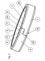
- FIG. 2 shows the sliding ring 1 from FIG. 1 in a perspective view.
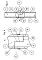
- FIG. 3 shows the sliding ring from FIG. 2 in a top view in the region of the cut-through 9.
- the slide ring 1 has at a point 5 of its circumference 6 an axially extending from a 7 to the other end face 8 through-section 9, wherein the transection 9, as shown in the plan view Figures 3 and 4, is substantially Z-shaped.
- the transection 9 thereby has in each case a frontal axial slot 15, 16, wherein the mutually facing sides of the axial slots 15, 16 are connected by the circumferential slot 17 with each other.
- the sliding ring 1 has on both sides of the region of the cut-through 9 at least one cam 10, 11 extending in the axial direction, which can be applied to the respective axially adjacent boundary wall 12, 13 of the installation groove 14 (see FIG. 1) ,
- the cams 10, 11 are arranged in the region of the circumferential extent of the circumferential slot 17 and, viewed in the circumferential direction, arranged axially opposite each other and formed coincident.
- each end face 7, 8 of the sliding ring 1 more, preferably at least three evenly distributed circumferentially arranged cam to minimize the risk of tilting of the sealing ring in the installation groove 14 and to achieve a particularly accurate positioning.
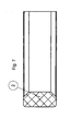
- FIG. 7 shows an exemplary embodiment of a pressure ring 2, which consists of elastomeric material and is provided for pressing the sliding ring 1 against the surface 3 of the machine element 4 to be sealed.
Landscapes
- Engineering & Computer Science (AREA)
- General Engineering & Computer Science (AREA)
- Mechanical Engineering (AREA)
- Sealing Devices (AREA)
- Gasket Seals (AREA)
Abstract
Description
- Die Erfindung betrifft einen Dichtring, umfassend einen Gleitring und einen Anpressring zur Anpressung des Gleitrings an die Oberfläche eines abzudichtenden Maschinenelements.
- Solche Dichtringe sind allgemein bekannt und gelangen beispielsweise zur Abdichtung von relativ zueinander translatorisch hin- und her bewegbaren Maschinenelementen zur Anwendung. Die Dichtringe können als Kolben- oder Stangendichtungen ausgebildet sein. Der Gleitring kann beispielsweise aus einem polymeren Werkstoff bestehen, und der Anpressring kann beispielsweise durch einen O-Ring gebildet sein, der aus einem gummielastische Werkstoff besteht. Für manche Anwendungsfälle ist es nachteilig, wenn der Gleitring in sich geschlossen ausgebildet ist. Ohne größeren Montageaufwand lässt sich der Gleitring dann weder montieren noch demontieren.
- Der Erfindung liegt die Aufgabe zu Grunde, einen Dichtring der eingangs genannten Art derart weiter zu entwickeln, dass die Montage oder Demontage in jedem Fall vereinfacht ist und dass der Dichtring, insbesondere der Gleitring, gute Gebrauchseigenschaften während einer langen Gebrauchsdauer aufweist. Der Gleitring soll außerdem eine gute Abdichtung der gegeneinander abzudichtenden Räume gewährleisten.
- Diese Aufgabe wird erfindungsgemäß durch einen Dichtring mit den Merkmalen von Anspruch 1 gelöst.
Auf eine vorteilhafte Ausgestaltung nehmen die auf Anspruch 1 rückbezogenen Ansprüche Bezug. - Zur Lösung der Aufgabe ist ein Dichtring vorgesehen, umfassend einen Gleitring und einen Anpressring zur Anpressung des Gleitrings an die Oberfläche eines abzudichtenden Maschinenelements, wobei der Gleitring an einer Stelle seines Umfangs eine sich axial von einer zur anderen Stirnseite erstreckende Durchtrennung aufweist, wobei der Gleitring stirnseitig zumindest einerseits im Bereich der Durchtrennung zumindest einen sich in axialer Richtung erstreckenden Nocken aufweist, der an einer axial benachbarten Begrenzungswand einer Einbaunut anlegbar ist.
- Die Durchtrennung im Gleitring bedingt eine einfache Montage des Gleitrings auch dann, wen die Einbaunut nur schwer zugänglich ist und/oder wenn zur Montage/Demontage eines in sich geschlossenen Gleitrings ein hoher Aufwand nötig wäre, weil beispielsweise eine Maschine, in der der Dichtring zur Anwendung gelangt, weitgehend zerlegt werden müsste.
- Generell besteht bei einem Gleitring mit Durchtrennung die Gefahr, dass die Dichtwirkung eingeschränkt ist und dass die gegeneinander abzudichtenden Räume durch die Durchtrennung miteinander verbunden sind und Leckage dadurch unerwünscht von einem abzudichtenden Raum in den anderen gelangt. Dieser Nachteil ist hauptsächlich darauf zurück zu führen, dass sich die die Durchtrennung begrenzenden Enden des Gleitrings während der bestimmungsgemäßen Verwendung des Dichtrings relativ zueinander bewegen und dadurch unerwünscht erhöhte Leckage und/oder eine Förderwirkung des abzudichtenden Mediums bedingt ist. Die Leckage ist umso größer, je größer der durch die Durchtrennung gebildete Spalt ist.
- Die Relativbewegung der die Durchtrennung begrenzenden Enden des Gleitrings wird durch die sich in axialer Richtung erstreckenden Nocken auf ein Minimum begrenzt, da die Nocken während der bestimmungsgemäßen Verwendung des Dichtrings an der jeweils axial benachbarten Begrenzungswand der Einbaunut anliegen.
- Trotz der einfachen Montage des durch die Durchtrennung geschlitzten Gleitrings weist dieser durch die Funktion und Anordnung der Nocken ausgezeichnete Gebrauchseigenschaften während einer langen Gebrauchsdauer auf, die sich von einem in sich geschlossenen Gleitring auch im Hinblick auf Abdichtleistung praktisch nicht unterscheiden.
- Bevorzugt weist der Gleitring stirnseitig beiderseits im Bereich der Durchtrennung jeweils zumindest einen sich in axialer Richtung erstreckenden Nocken auf, wobei beide Nocken an die jeweils axial benachbarte Begrenzungswand der Einbaunut anlegbar sind. Durch die Nocken stirnseitig beiderseits des Gleitrings werden der Gleitring und dadurch der gesamte Dichtring selbsttätig in der Einbaunut in axialer Richtung zentriert. Dies ist insbesondere im Bereich der Durchtrennung zur Erzielung der zuvor beschriebenen guten Gebrauchseigenschaften sehr vorteilhaft. Außerdem besteht die Möglichkeit, dass stimseitig beiderseits jeweils gleichmäßig in Umfangsrichtung verteilt angeordnete Nocken vorgesehen sind, so dass der Gleitring auch im Bereich außerhalb der Durchtrennung in der Einbaunut in axialer Richtung fixiert ist.
- Das Abdichtungsergebnis der gegeneinander abzudichtenden Räume ist besonders gut, wenn die Durchtrennung, in einer Draufsicht auf den Gleitring betrachtet, im Wesentlichen Z-förmig ausgebildet ist. In einem solchen Fall ist die Durchtrennung durch jeweils einen stirnseitigen Axialschlitz gebildet, deren einander zugewandte Seiten durch einen Umfangsschlitz miteinander verbunden sind. Durch eine solche Ausgestaltung ist die Durchtrennung im Wesentlichen labyrinthförmig, wobei die den Umfangsschlitz begrenzenden Bereiche der Enden des Gleitrings einander anliegend berühren. Die Berührung wird dadurch erreicht, dass die axiale Länge des Gleitrings im Bereich der Durchtrennung einschließlich der Nocken zumindest der axialen Länge der Einbaunut entspricht. Bevorzugt ist der Gleitring in axialer Richtung vorgespannt innerhalb der Einbaunut angeordnet, so dass auch die einander axial benachbart zugeordneten Begrenzungen des Umfangsschlitzes einander unter axialer Vorspannung dichtend berühren.
- Weiter bevorzugt sind die Nocken dabei im Bereich der Umfangserstreckung des Umfangsschlitzes, in Umfangsrichtung betrachtet, einander axial gegenüberliegend angeordnet. Ein Verkanten der Enden des Gleitrings, die die Durchtrennung begrenzen, kann dadurch weitgehend ausgeschlossen werden.
- Die Nocken können mit dem Gleitring jeweils einstückig ineinander übergehend und materialeinheitlich ausgebildet sein. Die Herstellung eines solchen Gleitrings ist dadurch einfach und kostengünstig. Die Nocken können übereinstimmend ausgebildet sein. Sie weisen dadurch übereinstimmende Gebrauchseigenschaften auf, beispielsweise eine übereinstimmende Anpresskraft, auf den Umfangsschlitz des in axialer Richtung in der Einbaunut zentrierten Gleitrings.
- Die Nocken können, in radialer Richtung betrachtet, in axialer Richtung konvex vorgewölbt sein. Außerdem oder alternativ besteht die Möglichkeit, dass die Nocken, in Umfangsrichtung betrachtet, in axialer Richtung konvex vorgewölbt sind. Sind die Nocken beispielsweise im Wesentlichen halbkugelförmig ausgebildet, ist die Montage des Dichtrings in die Einbaunut sehr einfach, da sich solche Nocken mit geringem Kraftaufwand einfach elastisch verformen lassen.
- Der Gleitring besteht bevorzugt aus einem polymeren Werkstoff, beispielsweise Polyamid.
- Der Anpressring besteht bevorzugt aus einem elastomeren Werkstoff, beispielsweise HNBR (Hydrogenated Nitrile Butadiene Rubber).
- Außerdem betrifft die Erfindung eine Dichtungsanordnung zur Abdichtung von zwei relativ zueinander beweglichen Maschinenelementen.
- Solche Dichtungsanordnungen, die beispielsweise relativ translatorisch zueinander bewegbare Maschinenelemente abdichten, sind allgemein bekannt, wobei eines der Maschinenelemente ein radial in Richtung des anderen Maschinenelements offene Einbaunut für einen Dichtring aufweist. Die Dichtringe können beispielsweise zweiteilig ausgebildet sein und einen Gleitring und einen Anpressring zur Anpressung des Gleitrings an die Oberfläche des abzudichtenden Maschinenelements aufweisen. Der Dichtring kann als radial außen dichtende Kolbendichtung oder als radial innen dichtende Stangendichtung ausgebildet sein.
- Die Montage/Demontage solcher Dichtungsanordnungen mit in sich geschlossenem Gleitring ist häufig nachteilig.
- Der Erfindung liegt die Aufgabe zu Grunde, eine Dichtungsanordnung der vorbekannten Art derart weiter zu entwickeln, dass diese einfach montiert/demontiert werden kann, gute Gebrauchseigenschaften während einer langen Gebrauchsdauer aufweist, insbesondere eine gute Abdichtung der gegeneinander abzudichtenden Räume.
- Diese Aufgabe wird durch die Merkmale von Anspruch 13 gelöst. Auf vorteilhafte Ausgestaltungen nehmen die auf Anspruch 13 rückbezogenen Ansprüche Bezug.
- Zur Lösung der Aufgabe ist eine Dichtungsanordnung zur Abdichtung von zwei relativ zueinander beweglichen Maschinenelementen vorgesehen, wobei eines der Maschinenelemente eine radial in Richtung des anderen Maschinenelements offene Einbaunut für einen Dichtring gemäß einem der Ansprüche 1 bis 12 aufweist, wobei zumindest einer der Nocken an die jeweils axial benachbarte Begrenzungswand der Einbaunut angelegt ist. Bevorzugt sind bei der Dichtungsanordnung beide Nocken an die jeweils axial benachbarte Begrenzungswand der Einbaunut angelegt.
- Die Nocken berühren die jeweils axial benachbarte Begrenzungswand bevorzugt unter elastischer Vorspannung anliegend. Der Anpressring kann bei einer Kolbendichtung zwischen Nutgrund der Einbaunut und Innenumfangsfläche des Gleitrings unter elastischer Vorspannung dichtend angeordnet sein. Bei der zuvor beschriebenen Dichtungsanordnung ist von Vorteil, dass eine einfache Montage/Demontage des Gleitrings auch dann gewährleistet ist, wenn die Einbaunut nur schwer zugänglich ist und/oder wenn zur Montage/Demontage eines in sich geschlossenen Gleitrings ein hoher Aufwand nötig wäre, weil beispielsweise eine Maschine, in der der Dichtring zur Anwendung gelangt, weitgehend zerlegt werden müsste.
- Die Relativbewegung der die Durchtrennung begrenzenden Enden des Gleitrings wird durch die sich in axialer Richtung erstreckenden Nocken auf ein Minimum begrenzt, da die Nocken während der bestimmungsgemäßen Verwendung des Dichtrings an der jeweils axial benachbarten Begrenzungswand der Einbaunut anliegen.
- Trotz der einfachen Montage des durch die Durchtrennung geschlitzten Gleitrings weist dieser durch die Funktion und Anordnung der Nocken ausgezeichnete Gebrauchseigenschaften während einer langen Gebrauchsdauer auf, die sich von einem in sich geschlossenen Gleitring auch im Hinblick auf Abdichtleistung praktisch nicht unterscheiden.
- Durch die Nocken stimseitig beiderseits des Gleitrings werden der Gleitring und dadurch der gesamte Dichtring selbsttätig in der Einbaunut in axialer Richtung zentriert. Dies ist insbesondere im Bereich der Durchtrennung zur Erzielung der zuvor beschriebenen guten Gebrauchseigenschaften sehr vorteilhaft. Außerdem besteht die Möglichkeit, dass stirnseitig beiderseits jeweils gleichmäßig in Umfangsrichtung verteilt angeordnete Nocken vorgesehen sind, so dass der Gleitring auch im Bereich außerhalb der Durchtrennung in der Einbaunut in axialer Richtung fixiert ist.
- Außerdem betrifft die Erfindung die Verwendung eines Dichtrings nach einem der Ansprüche 1 bis 12 oder einer Dichtungsanordnung nach einem der Ansprüche 13 bis 16 in einer Schlagbohrmaschine. Insbesondere für eine solche Verwendung ist der beanspruchte Dichtring oder die beanspruchte Dichtungsanordnung von hervor zu hebendem Vorteil. Das Schlaggerät, das auf den Bohrer schlägt, muss gegenüber dem Bohrer abgedichtet werden, um zu verhindern, dass Verunreinigungen am Bohrer und am Schlaggerät vorbei ins Getriebe gelangen und dort zu einer Beschädigung/Zerstörung der Schlagbohrmaschine führen. Die Dichtung ist in einer radial nach außen offenen Nut des Schlaggeräts einer Schlagbohrmaschine angeordnet, das auf den Meisselbohrer wirkt. Auf der dem Meisselbohrer abgewandten Seite des Schlaggeräts ist der Erregerkolben angeordnet, der axial in Richtung des Meisselbohrers auf das Schlaggerät wirkt und auf der dem Meisselbohrer axial abgewandten Seite vom Antriebskolben beaufschlagt wird, dem ein Getriebe vorgeschaltet ist.
- Ein Ausführungsbeispiel des erfindungsgemäßen Dichtrings in einer erfindungsgemäßen Dichtungsanordnung ist in den Figuren gezeigt und wird im Folgenden näher beschrieben.
- Die Figuren zeigen:
- Fig. 1:
- einen Ausschnitt aus einer Dichtungsanordnung mit eingebautem Dichtring,
- Fig. 2:
- den Gleitring aus Fig. 1 in perspektivischer Darstellung,
- Fig. 3:
- den Gleitring aus Fig. 2 in einer Draufsicht auf die Durchtrennung,
- Fig. 4:
- einen vergrößerten Ausschnitt aus dem Gleitring aus Fig. 3 im Bereich der Durchtrennung,
- Fig. 5:
- den Gleitring aus Fig. 1 in einem Halbschnitt,
- Fig. 6:
- einen Nocken des Gleitrings aus Fig. 5 in vergrößerter Darstellung,
- Fig. 7:
- den Anpressring aus Fig. 1 in einem Halbschnitt.
- In Figur 1 ist ein Ausschnitt aus einer Dichtungsanordnung einer Schlagbohrmaschine gezeigt. Der Dichtring aus der Dichtungsanordnung umfasst einen Gleitring 1 und einen Anpressring 2 zur Anpressung des Gleitrings 1 an die Oberfläche 3 des abzudichtenden ersten Maschinenelements 4. Der Gleitring 1 besteht in dem hier gezeigten Ausführungsbeispiel aus Polyamid. Der Anpressring besteht aus einem gummielastischen Werkstoff, beispielsweise HNBR. Der Dichtring ist als radial außendichtende Kolbendichtung ausgebildet.
- Die Oberfläche 3 des abzudichtenden ersten Maschinenelements 4 begrenzt in dem hier gezeigten Ausführungsbeispiel eine Bohrung eines Gehäuses. Der Anpressring 2 ist unter elastischer radialer Vorspannung innerhalb der Einbaunut 14 angeordnet und berührt radial innenseitig den Nutgrund 19 und radial außenseitig die Innenumfangsfläche 20 des Gleitrings 1 unter radialer Vorspannung. Durch die radiale Kraft, die der Anpressring 2 auf den Gleitring 1 ausübt, wird dieser sicher an die abzudichtende Oberfläche 3 des abzudichtenden ersten Maschinenelements 4 angelegt.
- Der beanspruchte Dichtring ist in dem in Figur 1 gezeigten Ausführungsbeispiel als Kolbendichtung ausgebildet. Davon abweichend kann er jedoch auch als Stangendichtung ausgebildet sein. Das abzudichtende Maschinenelement wäre in diesem Fall eine Stange und der Gleitring würde die Oberfläche der abzudichtenden Stange unter elastischer Vorspannung anliegend berühren. Die Einbaunut 14 wäre dann in einem Gehäuse angeordnet und radial in Richtung der Stange offen.
- Im hier dargestellten Ausführungsbeispiel weist der Gleitring 1 an einer Stelle 5 seines Umfangs 6, die in den Figuren 2 bis 4 dargestellt ist, eine sich axial von einer 7 zur anderen Stirnseite 8 erstreckende Durchtrennung 9 auf, die die Montage des Dichtrings wesentlich vereinfacht. Trotz der Durchtrennung 9, 15, 16, 17 und deren axialer Verpressung, wird der Gleitring 1 durch den Anpressring 2 radial an die abzudichtende Oberfläche 3 dichtend angepresst. Der Gleitring 1 ist in dem hier gezeigten Ausführungsbeispiel stirnseitig beiderseits im Bereich der Durchtrennung 9 mit jeweils zumindest einem sich in axialer Richtung erstreckenden Nocken 10, 11 versehen, wobei beide Nocken 10, 11 an die jeweils axial benachbarte Begrenzungswand 12, 13 der Einbaunut 14 unter elastischer Vorspannung angelegt sind. Die Nocken 10, 11 sind jeweils einstückig ineinander übergehend und materialeinheitlich mit dem Gleitring 1 ausgebildet.
- In Figur 2 ist der Gleitring 1 aus Figur 1 in einer perspektivischen Ansicht gezeigt.
- In Figur 3 ist der Gleitring aus Figur 2 in einer Draufsicht im Bereich der Durchtrennung 9 dargestellt.
- In Figur 4 ist die Durchtrennung aus den Figuren 2 und 3 vergrößert gezeigt.
- Der Gleitring 1 weist an einer Stelle 5 seines Umfangs 6 eine sich axial von einer 7 zur anderen Stirnseite 8 erstreckende Durchtrennung 9 auf, wobei die Durchtrennung 9, wie in der Draufsicht Figuren 3 und 4 gezeigt, im Wesentlichen Z-förmig ausgebildet ist. Die Durchtrennung 9 hat dadurch jeweils einen stimseitigen Axialschlitz 15, 16, wobei die einander zugewandten Seiten der Axialschlitze 15, 16 durch den Umfangsschlitz 17 mit einander verbunden sind.
- Außerdem weist der Gleitring 1 im hier gezeigten Beispiel stirnseitig beiderseits dem Bereich der Durchtrennung 9 jeweils zumindest einen sich in axialer Richtung erstreckenden Nocken 10, 11 auf, die an die jeweils axial benachbarte Begrenzungswand 12, 13 der Einbaunut 14 (vergleiche Figur 1) anlegbar sind.
- Die Nocken 10, 11 sind im Bereich der Umfangserstreckung des Umfangsschlitzes 17 angeordnet und, in Umfangsrichtung betrachtet, einander axial gegenüberliegend angeordnet und übereinstimmend ausgebildet. Die Nocken 10, 11 sind, in radialer Richtung betrachtet, in axialer Richtung konvex vorgewölbt und, in Umfangsrichtung betrachtet, in axialer Richtung konvex vorgewölbt. Dadurch, dass die Nocken 10, 11 jeweils unter axialer Vorspannung an den jeweils axial benachbarten Begrenzungswandungen 12, 13 der Einbaunut 14 anliegen, ist auch der Umfangsschlitz 17 während der bestimmungsgemäßen Verwendung des Dichtrings dicht, da die den Umfangsschlitz 17 begrenzenden Wandungen unter axialer Vorspannung dichtend aneinander angelegt sind.
- Generell besteht die Möglichkeit, an jeder Stirnseite 7, 8 des Gleitrings 1 mehrere, bevorzugt zumindest drei gleichmäßig in Umfangsrichtung verteilt angeordnete Nocken vorzusehen, um die Gefahr von Verkantungen des Dichtrings in der Einbaunut 14 zu minimieren und eine besonders exakte Positionierung zu erreichen.
- In Figur 5 ist der Gleitring 1 aus Figur 1 in einem Halbschnitt dargestellt. Der Umfangsschlitz 17 und die Nocken 10, 11 im Bereich der Stirnseiten 7, 8 sind jeweils gut zu erkennen.
- In Figur 6 ist eine der Stirnseiten 7, 8 mit dem jeweiligen Nocken 10, 11 vergrößert dargestellt. Der Nocken 10, 11 ist, in radialer Richtung betrachtet, in axialer Richtung konvex vorgewölbt.
- In Figur 7 ist ein Ausführungsbeispiel eines Anpressrings 2 gezeigt, der aus elastomerem Werkstoff besteht und zur Anpressung des Gleitrings 1 an die Oberfläche 3 des abzudichtenden Maschinenelements 4 vorgesehen ist.
-
- 1
- Gleitring
- 2
- Anpressring
- 3
- Oberfläche von 4
- 4
- Abzudichtendes erstes Maschinenelement
- 5
- Stelle der Durchtrennung 9 am Umfang 6
- 6
- Umfang
- 7
- Linke Stirnseite von 1
- 8
- Rechte Stirnseite von 1
- 9
- Durchtrennung
- 10
- Linker Nocken
- 11
- Rechter Nocken
- 12
- Begrenzungswand links
- 13
- Begrenzungswand rechts
- 14
- Einbaunut
- 15
- Axialschlitz links
- 16
- Axialschlitz rechts
- 17
- Umfangsschlitz
- 18
- Zweites Maschinenelement
- 19
- Nutgrund von 14
- 20
- Innenumfangsfläche von 1
Claims (17)
- Dichtring, umfassend einen Gleitring (1) und einen Anpressring (2) zur Anpressung des Gleitrings (1) an die Oberfläche (3) eines abzudichtenden Maschinenelements (4), wobei der Gleitring (1) an einer Stelle (5) seines Umfangs (6) eine sich axial von einer (7) zur anderen Stirnseite (8) erstreckende Durchtrennung (9) aufweist, wobei der Gleitring (1) stimseitig zumindest einerseits im Bereich der Durchtrennung (9) zumindest einen sich in axialer Richtung erstreckenden Nocken (10, 11) aufweist, der an einer axial benachbarten Begrenzungswand (12, 13) einer Einbaunut (14) anlegbar ist.
- Dichtring nach Anspruch 1, dadurch gekennzeichnet, dass der Gleitring (1) stimseitig beiderseits im Bereich der Durchtrennung (9) jeweils zumindest einen sich in axialer Richtung erstreckenden Nocken (10,11) aufweist und dass beide Nocken (10, 11) an die jeweils axial benachbarte Begrenzungswand (12, 13) der Einbaunut (14) anlegbar sind.
- Dichtring nach einem der Ansprüche 1 oder 2, dadurch gekennzeichnet, dass die Durchtrennung (9), in einer Draufsicht auf den Gleitring (1) betrachtet, im Wesentlichen Z-förmig ausgebildet ist.
- Dichtring nach einem der Ansprüche 1 bis 3, dadurch gekennzeichnet, dass die Durchtrennung (9) durch jeweils einen stimseitigen Axialschlitz (15, 16) gebildet ist, deren einander zugewandte Seiten durch einen Umfangsschlitz (17) mit einander verbunden sind.
- Dichtring nach einem der Ansprüche 1 bis 4, dadurch gekennzeichnet, dass die Nocken (10, 11) im Bereich der Umfangserstreckung des Umfangsschlitzes (17) angeordnet sind.
- Dichtring nach einem der Ansprüche 1 bis 5, dadurch gekennzeichnet, dass die Nocken (10, 11), in Umfangsrichtung betrachtet, einander axial gegenüber liegend angeordnet sind.
- Dichtring nach einem der Ansprüche 1 bis 6, dadurch gekennzeichnet, dass die Nocken (10, 11) mit dem Gleitring (1) jeweils einstückig ineinander übergehend und materialeinheitlich ausgebildet sind.
- Dichtring nach einem der Ansprüche 1 bis 7, dadurch gekennzeichnet, dass die Nocken (10, 11) übereinstimmend ausgebildet sind.
- Dichtring nach einem der Ansprüche 1 bis 8, dadurch gekennzeichnet, dass die Nocken (10, 11), in radialer Richtung betrachtet, in axialer Richtung konvex vorgewölbt sind.
- Dichtring nach einem der Ansprüche 1 bis 9, dadurch gekennzeichnet, dass die Nocken (10, 11), in Umfangsrichtung betrachtet, in axialer Richtung konvex vorgewölbt sind.
- Dichtring nach einem der Ansprüche 1 bis 10, dadurch gekennzeichnet, dass der Gleitring (1) aus einem polymeren Werkstoff besteht.
- Dichtring nach einem der Ansprüche 1 bis 11, dadurch gekennzeichnet, dass der Anpressring (2) aus einem elastomeren Werkstoff besteht.
- Dichtungsanordnung zur Abdichtung von zwei relativ zueinander beweglichen Maschinenelementen (4, 18), wobei eines der Maschinenelemente (18) eine radial in Richtung des anderen Maschinenelements (4) offene Einbaunut (14) für einen Dichtring gemäß einem der Ansprüche 1 bis 12 aufweist, wobei zumindest einer der Nocken (10, 11) an die jeweils axial benachbarte Begrenzungswand (12, 13) der Einbaunut (14) angelegt ist.
- Dichtungsanordnung nach Anspruch 13, dadurch gekennzeichnet, dass beide Nocken (10, 11) an die jeweils axial benachbarte Begrenzungswand (12, 13) der Einbaunut (14) angelegt sind.
- Dichtungsanordnung nach einem der Ansprüche 13 oder 14, dadurch gekennzeichnet, dass die Nocken (10, 11) die jeweils axial benachbarte Begrenzungswand (12, 13) unter elastischer Vorspannung anliegend berührt.
- Dichtungsanordnung nach einem der Ansprüche 13 bis 15, dadurch gekennzeichnet, dass der Anpressring (2) zwischen Nutgrund (19) der Einbaunut (14) und Innenumfangsfläche (20) des Gleitrings (1) unter elastischer Vorspannung dichtend angeordnet ist.
- Verwendung eines Dichtrings nach einem der Ansprüche 1 bis 12 oder einer Dichtungsanordnung nach einem der Ansprüche 13 bis 16 in einer Schlagbohrmaschine.
Applications Claiming Priority (1)
| Application Number | Priority Date | Filing Date | Title |
|---|---|---|---|
| DE102005059926A DE102005059926A1 (de) | 2005-12-13 | 2005-12-13 | Dichtring und Dichtungsanordnung sowie deren Verwendung |
Publications (3)
| Publication Number | Publication Date |
|---|---|
| EP1798454A2 true EP1798454A2 (de) | 2007-06-20 |
| EP1798454A3 EP1798454A3 (de) | 2007-07-18 |
| EP1798454B1 EP1798454B1 (de) | 2010-10-20 |
Family
ID=37781839
Family Applications (1)
| Application Number | Title | Priority Date | Filing Date |
|---|---|---|---|
| EP06023279A Not-in-force EP1798454B1 (de) | 2005-12-13 | 2006-11-09 | Dichtring und Dichtungsanordnung sowie deren Verwendung |
Country Status (3)
| Country | Link |
|---|---|
| EP (1) | EP1798454B1 (de) |
| AT (1) | ATE485468T1 (de) |
| DE (2) | DE102005059926A1 (de) |
Cited By (2)
| Publication number | Priority date | Publication date | Assignee | Title |
|---|---|---|---|---|
| EP2423539A1 (de) * | 2010-08-31 | 2012-02-29 | Burckhardt Compression AG | Dichtungsanordnung |
| EP2484942A4 (de) * | 2009-10-02 | 2016-02-24 | Nok Corp | Dichtungsvorrichtung |
Families Citing this family (1)
| Publication number | Priority date | Publication date | Assignee | Title |
|---|---|---|---|---|
| DE102018100637B3 (de) | 2018-01-12 | 2019-06-06 | Dürr Systems Ag | Dichtung und Beschichtungsmittelpumpe mit einer solchen Dichtung |
Family Cites Families (10)
| Publication number | Priority date | Publication date | Assignee | Title |
|---|---|---|---|---|
| DE1025210B (de) * | 1953-05-13 | 1958-02-27 | Kloeckner Humboldt Deutz Ag | Kolbenring mit gasdichtem Schloss fuer Arbeitskolben von Brennkraftmaschinen |
| SE375591B (de) * | 1973-08-28 | 1975-04-21 | Skega Ab | |
| DE2507222A1 (de) * | 1975-02-20 | 1976-09-09 | Praedifa Jaeger Kg | Gleitringdichtung fuer kolbenstangen |
| EP0011218B1 (de) * | 1978-11-10 | 1984-09-12 | Halifax Tool Company Limited | Abdichtung und Rückhaltung von teleskopisch verbundenen Elementen |
| DE3016231C2 (de) * | 1980-04-26 | 1983-05-05 | Kaco Gmbh + Co, 7100 Heilbronn | Dichtungsanordnung |
| DE3577132D1 (de) * | 1984-12-01 | 1990-05-17 | Freudenberg Carl Fa | Stangen- oder kolbendichtung. |
| DE4228438C1 (de) * | 1992-08-26 | 1994-01-13 | Festo Kg | Dichtungsring für Mehrwegeventile |
| DE29605476U1 (de) * | 1996-03-25 | 1997-07-24 | O&K Orenstein & Koppel AG, 13581 Berlin | Kolbenstangendichtung |
| DE10117662C1 (de) * | 2001-04-09 | 2003-01-16 | Freudenberg Carl Kg | Stangen- oder Kolbenprimärdichtung |
| DE20315344U1 (de) * | 2003-10-06 | 2004-02-19 | Bürkert Werke GmbH & Co. KG | Kolbendichtungssystem |
-
2005
- 2005-12-13 DE DE102005059926A patent/DE102005059926A1/de not_active Withdrawn
-
2006
- 2006-11-09 EP EP06023279A patent/EP1798454B1/de not_active Not-in-force
- 2006-11-09 DE DE502006008123T patent/DE502006008123D1/de active Active
- 2006-11-09 AT AT06023279T patent/ATE485468T1/de active
Non-Patent Citations (1)
| Title |
|---|
| None |
Cited By (6)
| Publication number | Priority date | Publication date | Assignee | Title |
|---|---|---|---|---|
| EP2484942A4 (de) * | 2009-10-02 | 2016-02-24 | Nok Corp | Dichtungsvorrichtung |
| EP2423539A1 (de) * | 2010-08-31 | 2012-02-29 | Burckhardt Compression AG | Dichtungsanordnung |
| WO2012028661A1 (de) * | 2010-08-31 | 2012-03-08 | Burckhardt Compression Ag | Dichtungsanordnung |
| CN103201541A (zh) * | 2010-08-31 | 2013-07-10 | 伯克哈特压缩机股份公司 | 密封装置 |
| US8985588B2 (en) | 2010-08-31 | 2015-03-24 | Burckhardt Compression Ag | Seal arrangement |
| CN103201541B (zh) * | 2010-08-31 | 2015-05-27 | 伯克哈特压缩机股份公司 | 密封装置 |
Also Published As
| Publication number | Publication date |
|---|---|
| DE502006008123D1 (de) | 2010-12-02 |
| DE102005059926A1 (de) | 2007-06-21 |
| EP1798454B1 (de) | 2010-10-20 |
| ATE485468T1 (de) | 2010-11-15 |
| EP1798454A3 (de) | 2007-07-18 |
Similar Documents
| Publication | Publication Date | Title |
|---|---|---|
| DE60133449T2 (de) | Fluidfilter und ein Fluidfilter-Filterkopf-Gerät | |
| EP2027403B1 (de) | Dichtungsanordnung zur druckentlastung | |
| EP2063157B1 (de) | Gleitringdichtungsanordnung | |
| WO1987006991A1 (fr) | Dispositif d'etancheite | |
| EP0902220A2 (de) | Dichtungsanordnung | |
| DE202008003418U1 (de) | Doppel-Dichtungsanordnung | |
| DE102011101968A1 (de) | Fluiddruckvorrichtung | |
| DE102006057364B4 (de) | Wasserhydraulische Maschine | |
| EP2827026B1 (de) | Dichtungsanordnung und Dichtring | |
| DE19728605C2 (de) | Stangen- oder Kolbendichtung | |
| EP3928002B1 (de) | Druckumkehr geeignete gleitringdichtungsanordnung | |
| EP0832382B1 (de) | Trockenlaufdichtungsring | |
| EP1798454B1 (de) | Dichtring und Dichtungsanordnung sowie deren Verwendung | |
| EP0988454B1 (de) | Dichtring eines schwenkmotors | |
| DE102004010432B3 (de) | Dichtungseinrichtung für einen radialen Schwenkmotor | |
| EP3149366B1 (de) | Dicht- oder abstreifring | |
| EP3246605A1 (de) | Membranventil | |
| DE69710244T2 (de) | Fluiddruckzylinder mit Schlagdämpfungsvorrichtungen | |
| DE2546805B2 (de) | Dichtring für drehbare Körper, wie Wellen o.dgl | |
| WO2006110929A1 (de) | Segmentierter packungsring | |
| EP0412997A1 (de) | Dichtungsanordnung. | |
| EP2228543B1 (de) | Schwenkflügelmotor | |
| DE4317483A1 (de) | Kolben, insbesondere für den Servozylinder einer Hilfskraftlenkanlage | |
| EP0561038B1 (de) | Dichtung für ein hin- und hergehendes Maschinenteil | |
| DE102016212311A1 (de) | Ventil mit über Dichtungsnut entlüftetem Steuerraum |
Legal Events
| Date | Code | Title | Description |
|---|---|---|---|
| PUAI | Public reference made under article 153(3) epc to a published international application that has entered the european phase |
Free format text: ORIGINAL CODE: 0009012 |
|
| PUAL | Search report despatched |
Free format text: ORIGINAL CODE: 0009013 |
|
| AK | Designated contracting states |
Kind code of ref document: A2 Designated state(s): AT BE BG CH CY CZ DE DK EE ES FI FR GB GR HU IE IS IT LI LT LU LV MC NL PL PT RO SE SI SK TR |
|
| AX | Request for extension of the european patent |
Extension state: AL BA HR MK YU |
|
| AK | Designated contracting states |
Kind code of ref document: A3 Designated state(s): AT BE BG CH CY CZ DE DK EE ES FI FR GB GR HU IE IS IT LI LT LU LV MC NL PL PT RO SE SI SK TR |
|
| AX | Request for extension of the european patent |
Extension state: AL BA HR MK YU |
|
| 17P | Request for examination filed |
Effective date: 20070809 |
|
| 17Q | First examination report despatched |
Effective date: 20070927 |
|
| AKX | Designation fees paid |
Designated state(s): AT BE BG CH CY CZ DE DK EE ES FI FR GB GR HU IE IS IT LI LT LU LV MC NL PL PT RO SE SI SK TR |
|
| GRAP | Despatch of communication of intention to grant a patent |
Free format text: ORIGINAL CODE: EPIDOSNIGR1 |
|
| GRAS | Grant fee paid |
Free format text: ORIGINAL CODE: EPIDOSNIGR3 |
|
| GRAA | (expected) grant |
Free format text: ORIGINAL CODE: 0009210 |
|
| AK | Designated contracting states |
Kind code of ref document: B1 Designated state(s): AT BE BG CH CY CZ DE DK EE ES FI FR GB GR HU IE IS IT LI LT LU LV MC NL PL PT RO SE SI SK TR |
|
| REG | Reference to a national code |
Ref country code: GB Ref legal event code: FG4D Free format text: NOT ENGLISH |
|
| REG | Reference to a national code |
Ref country code: CH Ref legal event code: EP |
|
| REG | Reference to a national code |
Ref country code: IE Ref legal event code: FG4D Free format text: LANGUAGE OF EP DOCUMENT: GERMAN |
|
| REF | Corresponds to: |
Ref document number: 502006008123 Country of ref document: DE Date of ref document: 20101202 Kind code of ref document: P |
|
| REG | Reference to a national code |
Ref country code: NL Ref legal event code: VDEP Effective date: 20101020 |
|
| LTIE | Lt: invalidation of european patent or patent extension |
Effective date: 20101020 |
|
| PG25 | Lapsed in a contracting state [announced via postgrant information from national office to epo] |
Ref country code: LT Free format text: LAPSE BECAUSE OF FAILURE TO SUBMIT A TRANSLATION OF THE DESCRIPTION OR TO PAY THE FEE WITHIN THE PRESCRIBED TIME-LIMIT Effective date: 20101020 |
|
| REG | Reference to a national code |
Ref country code: IE Ref legal event code: FD4D |
|
| BERE | Be: lapsed |
Owner name: CARL FREUDENBERG K.G. Effective date: 20101130 |
|
| PG25 | Lapsed in a contracting state [announced via postgrant information from national office to epo] |
Ref country code: PT Free format text: LAPSE BECAUSE OF FAILURE TO SUBMIT A TRANSLATION OF THE DESCRIPTION OR TO PAY THE FEE WITHIN THE PRESCRIBED TIME-LIMIT Effective date: 20110221 Ref country code: LV Free format text: LAPSE BECAUSE OF FAILURE TO SUBMIT A TRANSLATION OF THE DESCRIPTION OR TO PAY THE FEE WITHIN THE PRESCRIBED TIME-LIMIT Effective date: 20101020 Ref country code: IS Free format text: LAPSE BECAUSE OF FAILURE TO SUBMIT A TRANSLATION OF THE DESCRIPTION OR TO PAY THE FEE WITHIN THE PRESCRIBED TIME-LIMIT Effective date: 20110220 Ref country code: SE Free format text: LAPSE BECAUSE OF FAILURE TO SUBMIT A TRANSLATION OF THE DESCRIPTION OR TO PAY THE FEE WITHIN THE PRESCRIBED TIME-LIMIT Effective date: 20101020 Ref country code: NL Free format text: LAPSE BECAUSE OF FAILURE TO SUBMIT A TRANSLATION OF THE DESCRIPTION OR TO PAY THE FEE WITHIN THE PRESCRIBED TIME-LIMIT Effective date: 20101020 Ref country code: BG Free format text: LAPSE BECAUSE OF FAILURE TO SUBMIT A TRANSLATION OF THE DESCRIPTION OR TO PAY THE FEE WITHIN THE PRESCRIBED TIME-LIMIT Effective date: 20110120 Ref country code: SI Free format text: LAPSE BECAUSE OF FAILURE TO SUBMIT A TRANSLATION OF THE DESCRIPTION OR TO PAY THE FEE WITHIN THE PRESCRIBED TIME-LIMIT Effective date: 20101020 Ref country code: FI Free format text: LAPSE BECAUSE OF FAILURE TO SUBMIT A TRANSLATION OF THE DESCRIPTION OR TO PAY THE FEE WITHIN THE PRESCRIBED TIME-LIMIT Effective date: 20101020 |
|
| PG25 | Lapsed in a contracting state [announced via postgrant information from national office to epo] |
Ref country code: GR Free format text: LAPSE BECAUSE OF FAILURE TO SUBMIT A TRANSLATION OF THE DESCRIPTION OR TO PAY THE FEE WITHIN THE PRESCRIBED TIME-LIMIT Effective date: 20110121 Ref country code: MC Free format text: LAPSE BECAUSE OF NON-PAYMENT OF DUE FEES Effective date: 20101130 |
|
| REG | Reference to a national code |
Ref country code: CH Ref legal event code: PL |
|
| PG25 | Lapsed in a contracting state [announced via postgrant information from national office to epo] |
Ref country code: CH Free format text: LAPSE BECAUSE OF NON-PAYMENT OF DUE FEES Effective date: 20101130 Ref country code: EE Free format text: LAPSE BECAUSE OF FAILURE TO SUBMIT A TRANSLATION OF THE DESCRIPTION OR TO PAY THE FEE WITHIN THE PRESCRIBED TIME-LIMIT Effective date: 20101020 Ref country code: CZ Free format text: LAPSE BECAUSE OF FAILURE TO SUBMIT A TRANSLATION OF THE DESCRIPTION OR TO PAY THE FEE WITHIN THE PRESCRIBED TIME-LIMIT Effective date: 20101020 Ref country code: ES Free format text: LAPSE BECAUSE OF FAILURE TO SUBMIT A TRANSLATION OF THE DESCRIPTION OR TO PAY THE FEE WITHIN THE PRESCRIBED TIME-LIMIT Effective date: 20110131 Ref country code: IE Free format text: LAPSE BECAUSE OF FAILURE TO SUBMIT A TRANSLATION OF THE DESCRIPTION OR TO PAY THE FEE WITHIN THE PRESCRIBED TIME-LIMIT Effective date: 20101020 Ref country code: LI Free format text: LAPSE BECAUSE OF NON-PAYMENT OF DUE FEES Effective date: 20101130 |
|
| PLBE | No opposition filed within time limit |
Free format text: ORIGINAL CODE: 0009261 |
|
| STAA | Information on the status of an ep patent application or granted ep patent |
Free format text: STATUS: NO OPPOSITION FILED WITHIN TIME LIMIT |
|
| PG25 | Lapsed in a contracting state [announced via postgrant information from national office to epo] |
Ref country code: PL Free format text: LAPSE BECAUSE OF FAILURE TO SUBMIT A TRANSLATION OF THE DESCRIPTION OR TO PAY THE FEE WITHIN THE PRESCRIBED TIME-LIMIT Effective date: 20101020 Ref country code: SK Free format text: LAPSE BECAUSE OF FAILURE TO SUBMIT A TRANSLATION OF THE DESCRIPTION OR TO PAY THE FEE WITHIN THE PRESCRIBED TIME-LIMIT Effective date: 20101020 Ref country code: RO Free format text: LAPSE BECAUSE OF FAILURE TO SUBMIT A TRANSLATION OF THE DESCRIPTION OR TO PAY THE FEE WITHIN THE PRESCRIBED TIME-LIMIT Effective date: 20101020 Ref country code: DK Free format text: LAPSE BECAUSE OF FAILURE TO SUBMIT A TRANSLATION OF THE DESCRIPTION OR TO PAY THE FEE WITHIN THE PRESCRIBED TIME-LIMIT Effective date: 20101020 Ref country code: BE Free format text: LAPSE BECAUSE OF NON-PAYMENT OF DUE FEES Effective date: 20101130 |
|
| 26N | No opposition filed |
Effective date: 20110721 |
|
| GBPC | Gb: european patent ceased through non-payment of renewal fee |
Effective date: 20110120 |
|
| REG | Reference to a national code |
Ref country code: DE Ref legal event code: R097 Ref document number: 502006008123 Country of ref document: DE Effective date: 20110721 |
|
| PG25 | Lapsed in a contracting state [announced via postgrant information from national office to epo] |
Ref country code: GB Free format text: LAPSE BECAUSE OF NON-PAYMENT OF DUE FEES Effective date: 20110120 |
|
| PG25 | Lapsed in a contracting state [announced via postgrant information from national office to epo] |
Ref country code: CY Free format text: LAPSE BECAUSE OF FAILURE TO SUBMIT A TRANSLATION OF THE DESCRIPTION OR TO PAY THE FEE WITHIN THE PRESCRIBED TIME-LIMIT Effective date: 20101020 |
|
| PG25 | Lapsed in a contracting state [announced via postgrant information from national office to epo] |
Ref country code: LU Free format text: LAPSE BECAUSE OF NON-PAYMENT OF DUE FEES Effective date: 20101109 Ref country code: HU Free format text: LAPSE BECAUSE OF FAILURE TO SUBMIT A TRANSLATION OF THE DESCRIPTION OR TO PAY THE FEE WITHIN THE PRESCRIBED TIME-LIMIT Effective date: 20110421 |
|
| PG25 | Lapsed in a contracting state [announced via postgrant information from national office to epo] |
Ref country code: TR Free format text: LAPSE BECAUSE OF FAILURE TO SUBMIT A TRANSLATION OF THE DESCRIPTION OR TO PAY THE FEE WITHIN THE PRESCRIBED TIME-LIMIT Effective date: 20101020 |
|
| REG | Reference to a national code |
Ref country code: AT Ref legal event code: MM01 Ref document number: 485468 Country of ref document: AT Kind code of ref document: T Effective date: 20111109 |
|
| PG25 | Lapsed in a contracting state [announced via postgrant information from national office to epo] |
Ref country code: AT Free format text: LAPSE BECAUSE OF NON-PAYMENT OF DUE FEES Effective date: 20111109 |
|
| REG | Reference to a national code |
Ref country code: FR Ref legal event code: PLFP Year of fee payment: 10 |
|
| REG | Reference to a national code |
Ref country code: FR Ref legal event code: PLFP Year of fee payment: 11 |
|
| PGFP | Annual fee paid to national office [announced via postgrant information from national office to epo] |
Ref country code: DE Payment date: 20161205 Year of fee payment: 11 Ref country code: FR Payment date: 20161127 Year of fee payment: 11 |
|
| PGFP | Annual fee paid to national office [announced via postgrant information from national office to epo] |
Ref country code: IT Payment date: 20161130 Year of fee payment: 11 |
|
| REG | Reference to a national code |
Ref country code: DE Ref legal event code: R119 Ref document number: 502006008123 Country of ref document: DE |
|
| REG | Reference to a national code |
Ref country code: FR Ref legal event code: ST Effective date: 20180731 |
|
| PG25 | Lapsed in a contracting state [announced via postgrant information from national office to epo] |
Ref country code: DE Free format text: LAPSE BECAUSE OF NON-PAYMENT OF DUE FEES Effective date: 20180602 Ref country code: IT Free format text: LAPSE BECAUSE OF NON-PAYMENT OF DUE FEES Effective date: 20171109 Ref country code: FR Free format text: LAPSE BECAUSE OF NON-PAYMENT OF DUE FEES Effective date: 20171130 |