EP1798017A2 - Procédé et appareil pour fabriquer des récipients par soufflage - Google Patents
Procédé et appareil pour fabriquer des récipients par soufflage Download PDFInfo
- Publication number
- EP1798017A2 EP1798017A2 EP06023891A EP06023891A EP1798017A2 EP 1798017 A2 EP1798017 A2 EP 1798017A2 EP 06023891 A EP06023891 A EP 06023891A EP 06023891 A EP06023891 A EP 06023891A EP 1798017 A2 EP1798017 A2 EP 1798017A2
- Authority
- EP
- European Patent Office
- Prior art keywords
- radiation
- radiant heater
- emitted
- heating
- radiant
- Prior art date
- Legal status (The legal status is an assumption and is not a legal conclusion. Google has not performed a legal analysis and makes no representation as to the accuracy of the status listed.)
- Granted
Links
- 238000000034 method Methods 0.000 title claims abstract description 31
- 238000000071 blow moulding Methods 0.000 title claims abstract description 14
- 230000005855 radiation Effects 0.000 claims abstract description 99
- 238000010438 heat treatment Methods 0.000 claims abstract description 78
- 239000012815 thermoplastic material Substances 0.000 claims abstract description 9
- 230000003750 conditioning effect Effects 0.000 claims abstract description 3
- 238000007664 blowing Methods 0.000 claims description 23
- 238000000295 emission spectrum Methods 0.000 claims description 3
- 230000000717 retained effect Effects 0.000 claims description 2
- 239000000463 material Substances 0.000 abstract description 8
- 239000007789 gas Substances 0.000 description 11
- 238000012546 transfer Methods 0.000 description 9
- 238000001816 cooling Methods 0.000 description 8
- 239000011521 glass Substances 0.000 description 6
- 229920000139 polyethylene terephthalate Polymers 0.000 description 5
- 239000005020 polyethylene terephthalate Substances 0.000 description 5
- 239000000969 carrier Substances 0.000 description 3
- 238000000465 moulding Methods 0.000 description 3
- 238000001228 spectrum Methods 0.000 description 3
- 238000010276 construction Methods 0.000 description 2
- 238000013461 design Methods 0.000 description 2
- 238000010586 diagram Methods 0.000 description 2
- 238000001746 injection moulding Methods 0.000 description 2
- 238000004519 manufacturing process Methods 0.000 description 2
- QSHDDOUJBYECFT-UHFFFAOYSA-N mercury Chemical compound [Hg] QSHDDOUJBYECFT-UHFFFAOYSA-N 0.000 description 2
- 229910052753 mercury Inorganic materials 0.000 description 2
- 229910052756 noble gas Inorganic materials 0.000 description 2
- 238000005457 optimization Methods 0.000 description 2
- 230000035515 penetration Effects 0.000 description 2
- -1 polyethylene terephthalate Polymers 0.000 description 2
- 229910052724 xenon Inorganic materials 0.000 description 2
- FHNFHKCVQCLJFQ-UHFFFAOYSA-N xenon atom Chemical compound [Xe] FHNFHKCVQCLJFQ-UHFFFAOYSA-N 0.000 description 2
- VYPSYNLAJGMNEJ-UHFFFAOYSA-N Silicium dioxide Chemical compound O=[Si]=O VYPSYNLAJGMNEJ-UHFFFAOYSA-N 0.000 description 1
- 238000003491 array Methods 0.000 description 1
- 235000013361 beverage Nutrition 0.000 description 1
- 230000033228 biological regulation Effects 0.000 description 1
- 238000006243 chemical reaction Methods 0.000 description 1
- 230000001143 conditioned effect Effects 0.000 description 1
- 230000000694 effects Effects 0.000 description 1
- 238000005265 energy consumption Methods 0.000 description 1
- 238000011089 mechanical engineering Methods 0.000 description 1
- 229910052751 metal Inorganic materials 0.000 description 1
- 239000002184 metal Substances 0.000 description 1
- 150000002835 noble gases Chemical class 0.000 description 1
- 238000013021 overheating Methods 0.000 description 1
- 239000004033 plastic Substances 0.000 description 1
- 229920003023 plastic Polymers 0.000 description 1
- 238000012545 processing Methods 0.000 description 1
- 150000003839 salts Chemical class 0.000 description 1
- 238000004904 shortening Methods 0.000 description 1
- 239000007787 solid Substances 0.000 description 1
- 238000007711 solidification Methods 0.000 description 1
- 230000008023 solidification Effects 0.000 description 1
- 230000001629 suppression Effects 0.000 description 1
- 238000005496 tempering Methods 0.000 description 1
- 230000007704 transition Effects 0.000 description 1
- WFKWXMTUELFFGS-UHFFFAOYSA-N tungsten Chemical compound [W] WFKWXMTUELFFGS-UHFFFAOYSA-N 0.000 description 1
- 229910052721 tungsten Inorganic materials 0.000 description 1
- 239000010937 tungsten Substances 0.000 description 1
Images


Classifications
-
- B—PERFORMING OPERATIONS; TRANSPORTING
- B29—WORKING OF PLASTICS; WORKING OF SUBSTANCES IN A PLASTIC STATE IN GENERAL
- B29C—SHAPING OR JOINING OF PLASTICS; SHAPING OF MATERIAL IN A PLASTIC STATE, NOT OTHERWISE PROVIDED FOR; AFTER-TREATMENT OF THE SHAPED PRODUCTS, e.g. REPAIRING
- B29C49/00—Blow-moulding, i.e. blowing a preform or parison to a desired shape within a mould; Apparatus therefor
- B29C49/42—Component parts, details or accessories; Auxiliary operations
- B29C49/78—Measuring, controlling or regulating
-
- B—PERFORMING OPERATIONS; TRANSPORTING
- B29—WORKING OF PLASTICS; WORKING OF SUBSTANCES IN A PLASTIC STATE IN GENERAL
- B29C—SHAPING OR JOINING OF PLASTICS; SHAPING OF MATERIAL IN A PLASTIC STATE, NOT OTHERWISE PROVIDED FOR; AFTER-TREATMENT OF THE SHAPED PRODUCTS, e.g. REPAIRING
- B29C49/00—Blow-moulding, i.e. blowing a preform or parison to a desired shape within a mould; Apparatus therefor
- B29C49/08—Biaxial stretching during blow-moulding
- B29C49/10—Biaxial stretching during blow-moulding using mechanical means for prestretching
- B29C49/122—Drive means therefor
- B29C49/1229—Drive means therefor being a cam mechanism
-
- B—PERFORMING OPERATIONS; TRANSPORTING
- B29—WORKING OF PLASTICS; WORKING OF SUBSTANCES IN A PLASTIC STATE IN GENERAL
- B29C—SHAPING OR JOINING OF PLASTICS; SHAPING OF MATERIAL IN A PLASTIC STATE, NOT OTHERWISE PROVIDED FOR; AFTER-TREATMENT OF THE SHAPED PRODUCTS, e.g. REPAIRING
- B29C49/00—Blow-moulding, i.e. blowing a preform or parison to a desired shape within a mould; Apparatus therefor
- B29C49/42—Component parts, details or accessories; Auxiliary operations
- B29C49/64—Heating or cooling preforms, parisons or blown articles
- B29C49/6409—Thermal conditioning of preforms
- B29C49/6418—Heating of preforms
-
- B—PERFORMING OPERATIONS; TRANSPORTING
- B29—WORKING OF PLASTICS; WORKING OF SUBSTANCES IN A PLASTIC STATE IN GENERAL
- B29C—SHAPING OR JOINING OF PLASTICS; SHAPING OF MATERIAL IN A PLASTIC STATE, NOT OTHERWISE PROVIDED FOR; AFTER-TREATMENT OF THE SHAPED PRODUCTS, e.g. REPAIRING
- B29C35/00—Heating, cooling or curing, e.g. crosslinking or vulcanising; Apparatus therefor
- B29C35/02—Heating or curing, e.g. crosslinking or vulcanizing during moulding, e.g. in a mould
- B29C35/08—Heating or curing, e.g. crosslinking or vulcanizing during moulding, e.g. in a mould by wave energy or particle radiation
- B29C35/0805—Heating or curing, e.g. crosslinking or vulcanizing during moulding, e.g. in a mould by wave energy or particle radiation using electromagnetic radiation
- B29C2035/0822—Heating or curing, e.g. crosslinking or vulcanizing during moulding, e.g. in a mould by wave energy or particle radiation using electromagnetic radiation using IR radiation
-
- B—PERFORMING OPERATIONS; TRANSPORTING
- B29—WORKING OF PLASTICS; WORKING OF SUBSTANCES IN A PLASTIC STATE IN GENERAL
- B29C—SHAPING OR JOINING OF PLASTICS; SHAPING OF MATERIAL IN A PLASTIC STATE, NOT OTHERWISE PROVIDED FOR; AFTER-TREATMENT OF THE SHAPED PRODUCTS, e.g. REPAIRING
- B29C49/00—Blow-moulding, i.e. blowing a preform or parison to a desired shape within a mould; Apparatus therefor
- B29C49/42—Component parts, details or accessories; Auxiliary operations
- B29C49/78—Measuring, controlling or regulating
- B29C49/783—Measuring, controlling or regulating blowing pressure
- B29C2049/7831—Measuring, controlling or regulating blowing pressure characterised by pressure values or ranges
-
- B—PERFORMING OPERATIONS; TRANSPORTING
- B29—WORKING OF PLASTICS; WORKING OF SUBSTANCES IN A PLASTIC STATE IN GENERAL
- B29C—SHAPING OR JOINING OF PLASTICS; SHAPING OF MATERIAL IN A PLASTIC STATE, NOT OTHERWISE PROVIDED FOR; AFTER-TREATMENT OF THE SHAPED PRODUCTS, e.g. REPAIRING
- B29C49/00—Blow-moulding, i.e. blowing a preform or parison to a desired shape within a mould; Apparatus therefor
- B29C49/42—Component parts, details or accessories; Auxiliary operations
- B29C49/78—Measuring, controlling or regulating
- B29C49/786—Temperature
- B29C2049/7867—Temperature of the heating or cooling means
- B29C2049/78675—Temperature of the heating or cooling means of the heating means
-
- B—PERFORMING OPERATIONS; TRANSPORTING
- B29—WORKING OF PLASTICS; WORKING OF SUBSTANCES IN A PLASTIC STATE IN GENERAL
- B29C—SHAPING OR JOINING OF PLASTICS; SHAPING OF MATERIAL IN A PLASTIC STATE, NOT OTHERWISE PROVIDED FOR; AFTER-TREATMENT OF THE SHAPED PRODUCTS, e.g. REPAIRING
- B29C2949/00—Indexing scheme relating to blow-moulding
- B29C2949/07—Preforms or parisons characterised by their configuration
- B29C2949/0715—Preforms or parisons characterised by their configuration the preform having one end closed
-
- B—PERFORMING OPERATIONS; TRANSPORTING
- B29—WORKING OF PLASTICS; WORKING OF SUBSTANCES IN A PLASTIC STATE IN GENERAL
- B29C—SHAPING OR JOINING OF PLASTICS; SHAPING OF MATERIAL IN A PLASTIC STATE, NOT OTHERWISE PROVIDED FOR; AFTER-TREATMENT OF THE SHAPED PRODUCTS, e.g. REPAIRING
- B29C49/00—Blow-moulding, i.e. blowing a preform or parison to a desired shape within a mould; Apparatus therefor
- B29C49/02—Combined blow-moulding and manufacture of the preform or the parison
- B29C49/06—Injection blow-moulding
-
- B—PERFORMING OPERATIONS; TRANSPORTING
- B29—WORKING OF PLASTICS; WORKING OF SUBSTANCES IN A PLASTIC STATE IN GENERAL
- B29C—SHAPING OR JOINING OF PLASTICS; SHAPING OF MATERIAL IN A PLASTIC STATE, NOT OTHERWISE PROVIDED FOR; AFTER-TREATMENT OF THE SHAPED PRODUCTS, e.g. REPAIRING
- B29C49/00—Blow-moulding, i.e. blowing a preform or parison to a desired shape within a mould; Apparatus therefor
- B29C49/08—Biaxial stretching during blow-moulding
- B29C49/10—Biaxial stretching during blow-moulding using mechanical means for prestretching
- B29C49/12—Stretching rods
-
- B—PERFORMING OPERATIONS; TRANSPORTING
- B29—WORKING OF PLASTICS; WORKING OF SUBSTANCES IN A PLASTIC STATE IN GENERAL
- B29C—SHAPING OR JOINING OF PLASTICS; SHAPING OF MATERIAL IN A PLASTIC STATE, NOT OTHERWISE PROVIDED FOR; AFTER-TREATMENT OF THE SHAPED PRODUCTS, e.g. REPAIRING
- B29C49/00—Blow-moulding, i.e. blowing a preform or parison to a desired shape within a mould; Apparatus therefor
- B29C49/08—Biaxial stretching during blow-moulding
- B29C49/16—Biaxial stretching during blow-moulding using pressure difference for pre-stretching, e.g. pre-blowing
-
- B—PERFORMING OPERATIONS; TRANSPORTING
- B29—WORKING OF PLASTICS; WORKING OF SUBSTANCES IN A PLASTIC STATE IN GENERAL
- B29C—SHAPING OR JOINING OF PLASTICS; SHAPING OF MATERIAL IN A PLASTIC STATE, NOT OTHERWISE PROVIDED FOR; AFTER-TREATMENT OF THE SHAPED PRODUCTS, e.g. REPAIRING
- B29C49/00—Blow-moulding, i.e. blowing a preform or parison to a desired shape within a mould; Apparatus therefor
- B29C49/42—Component parts, details or accessories; Auxiliary operations
- B29C49/64—Heating or cooling preforms, parisons or blown articles
- B29C49/68—Ovens specially adapted for heating preforms or parisons
- B29C49/6835—Ovens specially adapted for heating preforms or parisons using reflectors
-
- B—PERFORMING OPERATIONS; TRANSPORTING
- B29—WORKING OF PLASTICS; WORKING OF SUBSTANCES IN A PLASTIC STATE IN GENERAL
- B29K—INDEXING SCHEME ASSOCIATED WITH SUBCLASSES B29B, B29C OR B29D, RELATING TO MOULDING MATERIALS OR TO MATERIALS FOR MOULDS, REINFORCEMENTS, FILLERS OR PREFORMED PARTS, e.g. INSERTS
- B29K2023/00—Use of polyalkenes or derivatives thereof as moulding material
- B29K2023/10—Polymers of propylene
- B29K2023/12—PP, i.e. polypropylene
-
- B—PERFORMING OPERATIONS; TRANSPORTING
- B29—WORKING OF PLASTICS; WORKING OF SUBSTANCES IN A PLASTIC STATE IN GENERAL
- B29K—INDEXING SCHEME ASSOCIATED WITH SUBCLASSES B29B, B29C OR B29D, RELATING TO MOULDING MATERIALS OR TO MATERIALS FOR MOULDS, REINFORCEMENTS, FILLERS OR PREFORMED PARTS, e.g. INSERTS
- B29K2067/00—Use of polyesters or derivatives thereof, as moulding material
Definitions
- the invention relates to a method for blow-molding of containers, in which a preform made of a thermoplastic material after thermal conditioning along a transport path in the region of a heating section within a blow mold is converted by blowing pressure into the container.
- the invention further relates to a device for blow-molding of containers made of a thermoplastic material, which has at least one heating path arranged along a transport path of a preform and a blowing station provided with a blow mold.
- thermoplastic material such as preforms made of PET (polyethylene terephthalate)
- preforms made of PET polyethylene terephthalate
- Blowing a heating device and a blowing device, in the region of the previously tempered preform is expanded by biaxial orientation to a container.
- the expansion takes place with the aid of compressed air, which is introduced into the preform to be expanded.
- the procedural sequence in such an expansion of the preform is in the DE-OS 43 40 291 explained.
- the introductory mentioned introduction of the pressurized gas also includes the introduction of compressed gas into the developing container bubble and the introduction of compressed gas into the preform at the beginning of the blowing process.
- the preforms as well as the blown containers can be transported by means of different handling devices.
- the use of transport mandrels, onto which the preforms are plugged, has proven to be useful.
- the preforms can also be handled with other support devices.
- the use of gripper tongs for handling preforms and the use of expansion mandrels which are insertable into a muzzle region of the preform for mounting are also among the available constructions.
- blow molding stations different embodiments are known.
- blow stations which are arranged on rotating transport wheels, a book-like unfoldability of the mold carrier is frequently encountered. But it is also possible to use relatively movable or differently guided mold carrier.
- fixed blowing stations which are particularly suitable for receiving a plurality of cavities for container molding, typically plates arranged parallel to one another are used as mold carriers.
- the preforms are typically attached to transport mandrels, which either transport the preform through the entire blow molding machine or circulate only in the region of the heating device.
- transport mandrels In a stationary heating of the preforms such that the mouths of the preforms are oriented in the vertical direction down, the preforms are usually attached to a sleeve-shaped support member of the transport mandrel.
- a suspended heating of the preforms in which they are oriented with their mouths in the vertical direction upwards, expanding mandrels are introduced into the mouths of the preforms, which clamp the preforms in the rule.
- thermoplastic material has pronounced thermally insulating properties, sufficient time for the preforms to heat up for about 20 seconds results in adequate heat propagation. To avoid overheating of the surface areas of the preform takes place at the same time for heating and blowing with cooling air. This results in a relatively high energy consumption for the implementation of the heating.
- the object of the present invention is to improve a method of the aforementioned type such that with low mechanical engineering effort a high-quality heating is supported at the same time high throughput rates.
- This object is achieved in that of At least one radiant heater in the region of the heating path, a heating radiation with a maximum radiation intensity at wavelengths between 0.4 microns and 1 micrometer is emitted.
- Another object of the present invention is to construct a device of the aforementioned type such that high throughput rates are supported with a simple structural design.
- At least one radiant heater arranged in the region of the heating section has a radiation emission spectrum with a maximum radiation intensity in a wavelength range from 0.4 micrometer to 1.0 micrometer.
- the selected length range does not require special shielding to avoid endangering the environment.
- a good compromise between a sufficient penetration of the heating radiation into the material of the preforms and a high conversion rate of the radiation energy into heat energy is provided by emitting the maximum radiation intensity with a wavelength of about 0.8 micrometer. Radiation intensity is in particular associated with a specific wavelength Signal amplitude or the energy content associated with this wavelength understood.
- An advantageous frequency spectrum of the heating radiation is provided by the fact that the heating radiation is emitted with a color temperature of at least 3000 ° Kelvin.
- the heating radiation is emitted with a color temperature of about 3500 ° Kelvin.
- the heating radiation is emitted with a color temperature of at least 3500 ° Kelvin.
- the heating radiation is emitted with a color temperature of at least 5000 ° Kelvin.
- An optimal heating behavior is provided by the fact that the heating radiation is imitated with a color temperature of about 6000 ° Kelvin.
- a further optimization of the frequency spectrum of the heating radiation is defined by the fact that 50% of the power of the emitted heating radiation is emitted in a wavelength range of +/- 0.5 micrometers relative to the wavelength of the maximum radiation intensity.
- the heating behavior is further improved by emitting 50% of the power of the emitted heating radiation in a wavelength range of +/- 0.4 microns, based on the wavelength of the maximum radiation intensity.
- 50% of the power of the emitted radiant heat will be emitted in a wavelength range of +/- 0.3 microns based on the wavelength of the maximum radiation intensity.
- a provision of the heating radiation with high reliability and sufficiently long operability of the radiant heater can be effected in that the heating radiation is emitted by a gas discharge lamp.
- Optimal controllability of the heating radiation with low power losses can be achieved by emitting the heating radiation from an LED array.
- a further optimization of the radiation characteristic can be effected in that the radiant heater is provided with a frequency-selective reflector.
- a further improved utilization of the emitted heating radiation can be achieved by at least a portion of the heating radiation being reflected by a frequency-selective reflector positioned in the radiation direction behind the preforms to be heated.
- a restraint unwanted proportions of the radiant spectrum emitted by the radiant heater can be effected in that a portion of the radiant heat emitted by the radiant heater is retained by a filter.
- the radiant heater be coupled with an electrical intensity control.
- Another embodiment variant is that the radiant heater is coupled with a mechanical intensity control.
- a suppression of currently not required radiation components in a substantially uniform operation of the radiant heater is achieved in that at least a portion of the heating radiation is deflected in a predetermined direction.
- a further variant for providing a controllability of the heating power in a constant operation of the radiant heater is effected in that at least a portion of the heating radiation is mirrored in a predeterminable direction.
- a very compact design of a control unit for the heating radiation can be achieved in that at least a portion of the heating radiation is directed by a controllable microlens array.
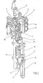
- FIG. 1 The basic structure of a device for forming preforms (1) in container (2) is shown in FIG. 1 and in FIG. 2.
- the device for forming the container (2) consists essentially of a blowing station (3), which is provided with a blow mold (4) into which a preform (1) can be inserted.
- the preform (1) may be an injection-molded part of polyethylene terephthalate.
- the blow mold (4) consists of mold halves (5, 6) and a bottom part (7), which is a lifting device (8) is positionable.
- the preform (1) can be held in the region of the blowing station (3) by a transport mandrel (9) which, together with the preform (1), passes through a plurality of treatment stations within the device. But it is also possible to use the preform (1), for example via pliers or other handling means directly into the blow mold (4).
- a connecting piston (10) is arranged, which feeds the preform (1) compressed air and at the same time makes a seal relative to the transport mandrel (9).
- a connecting piston (10) is arranged, which feeds the preform (1) compressed air and at the same time makes a seal relative to the transport mandrel (9).
- a stretching of the preform (1) takes place in this embodiment by means of a stretching rod (11), which is positioned by a cylinder (12).
- a mechanical positioning of the stretch rod (11) is carried out over curve segments, which are acted upon by Abgriff rollers.
- the use of curve segments is particularly useful when a plurality of blowing stations (3) are arranged on a rotating blowing wheel
- the stretching system is designed such that a tandem arrangement of two cylinders (12) is provided. From a primary cylinder (13), the stretch rod (11) is first moved to the area of a bottom (14) of the preform (1) before the beginning of the actual stretching operation.
- the primary cylinder (13) with extended stretching rod together with a carriage (15) carrying the primary cylinder (13) is positioned by a secondary cylinder (16) or via a cam control.
- the secondary cylinder (16) in such a cam-controlled manner that a current stretching position is predetermined by a guide roller (17) which slides along a curved path during the execution of the stretching operation.
- the guide roller (17) is pressed by the secondary cylinder (16) against the guideway.
- the carriage (15) slides along two guide elements (18).
- the carriers (19, 20) are locked relative to one another by means of a locking device (20).
- Fig. 2 shows in addition to the blown container (2) and dashed lines drawn the preform (1) and schematically a developing container bladder (23).
- Fig. 3 shows the basic structure of a blow molding machine, which is provided with a heating section (24) and a rotating blowing wheel (25).
- a preform input (26) the preforms (1) are transported by transfer wheels (27, 28, 29) into the region of the heating path (24).
- Heater (30) and fan (31) are arranged along the heating path (24) in order to temper the preforms (1).
- After a sufficient temperature control of the preforms (1) they are transferred to the blowing wheel (25), in the region of which the blowing stations (3) are arranged.
- the finished blown containers (2) are fed by further transfer wheels to a delivery line (32).
- thermoplastic material different plastics can be used. Suitable for example PET, PEN or PP.
- the expansion of the preform (1) during the orientation process is carried out by compressed air supply.
- the compressed air supply is in a Vorblasphase in which gas, for example, compressed air, is supplied at a low pressure level and divided into a subsequent Hauptblasphase in which gas is supplied at a higher pressure level.
- compressed air is typically used at a pressure in the interval of 10 bar to 25 bar and during the main blowing phase compressed air is supplied at a pressure in the interval of 25 bar to 40 bar.
- the heating section (24) from a plurality of revolving transport elements (33) is formed, which are strung together like a chain and guided by guide wheels (34).
- guide wheels (34) In particular, it is envisaged to open a substantially rectangular basic contour by the chain-like arrangement.
- a single relatively large-sized guide wheel (34) and in the region of adjacent deflections two comparatively smaller dimensioned guide wheels (36) used In principle, however, any other guides are conceivable.
- the arrangement shown to be particularly useful since in the region of the corresponding extent of the heating section (24) three deflecting wheels (34, 36) are positioned, and although in each case the smaller deflection wheels (36) in Range of the transition to the linear curves of the heating section (24) and the larger deflection wheel (34) in the immediate transfer area to the transfer wheel (29) and the input wheel (35).
- chain-like transport elements (33) it is also possible, for example, to use a rotating heating wheel.
- a larger amount of preforms (1) per unit time can be tempered by the larger number of radiant heaters (30).
- the fans (31) introduce cooling air into the region of cooling air ducts (39), which in each case oppose the associated radiant heaters (30) and emit the cooling air via outflow openings.
- a flow direction for the cooling air is realized substantially transversely to a transport direction of the preforms (1).
- the cooling air ducts (39) can provide reflectors for the heating radiation in the area opposite the radiant heaters (30), and it is likewise possible to realize cooling of the radiant heaters (30) via the discharged cooling air.
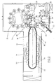
- Fig. 5 shows the basic structure of a radiation source (41) of the radiant heater (30).
- the radiation source (41) is formed as a gas discharge lamp, which consists essentially of a glass bulb (42) and two electrodes (43, 44) which are supported by sockets (45, 46).
- the glass bulb (42) is filled with a gas, such as xenon.
- a gas such as xenon.
- a high voltage of about 20,000 to 25,000 volts is applied to the electrodes (43, 44) and thereby an arc (47) is ignited.
- quartz glass is typically used due to the required temperature resistance.
- xenon other noble gases can be used to fill the glass bulb.
- mercury is introduced into the glass bulb (42) and the noble gas also present serves merely as a starting gas for igniting the arc (47). After ignition of the arc (47), the mercury vaporizes and provides the required discharge gas.
- tungsten As material for the electrodes (43, 44) tungsten can be used.
- the addition of metal salts into the interior of the glass bulb (42) is also advantageous for specifying a suitable radiation emission. As a result, in particular the emission spectrum of the radiation is influenced.
- Fig. 6 shows another embodiment for constructing a radiant heater (30).
- the radiation sources (41) are designed as light-emitting diodes.
- Currently available LED's generate a power of 10 watts with a diameter of about 8 mm. It can be installed on a surface of 10 x 10 cm, a radiator power between 1.0 and 1.5 kilowatts. Due to the almost complete implementation of the supply power of the LEDs in radiated power an extremely compact and energy-efficient heating is provided.
- a typical arrangement of the radiation sources (41) in the region of the radiant heater (30) is such that at least a plurality of radiation sources (21) are arranged one above the other in order to carry out a temperature profiling in a longitudinal direction of the preform (1).
- LEDs are used as radiation sources (41)
- two-dimensional arrays of radiation sources (41) are preferably constructed in order to achieve a high radiation intensity.
- the individual LEDs can each be controlled separately or in groups to specify the respective radiation intensity.
- An electrical intensity control of the radiation sources (41) can take place in different ways. Particularly suitable are control methods in which the color temperature of the emitted radiation is not or only insignificantly changed. In the case of radiation generation using arcs, it is particularly conceivable to vary the current through the arc at essentially the same supply voltage. It is also possible to vary the current or the voltage in the form of a pulse width modulation and thereby to provide a desired average energy output.
Landscapes
- Engineering & Computer Science (AREA)
- Manufacturing & Machinery (AREA)
- Mechanical Engineering (AREA)
- Physics & Mathematics (AREA)
- Thermal Sciences (AREA)
- Blow-Moulding Or Thermoforming Of Plastics Or The Like (AREA)
Applications Claiming Priority (1)
| Application Number | Priority Date | Filing Date | Title |
|---|---|---|---|
| DE102005060429.3A DE102005060429B4 (de) | 2005-12-15 | 2005-12-15 | Verfahren und Vorrichtung zur Blasformung von Behältern |
Publications (3)
| Publication Number | Publication Date |
|---|---|
| EP1798017A2 true EP1798017A2 (fr) | 2007-06-20 |
| EP1798017A3 EP1798017A3 (fr) | 2007-08-15 |
| EP1798017B1 EP1798017B1 (fr) | 2009-07-29 |
Family
ID=37814480
Family Applications (1)
| Application Number | Title | Priority Date | Filing Date |
|---|---|---|---|
| EP06023891A Active EP1798017B1 (fr) | 2005-12-15 | 2006-11-17 | Procédé et appareil pour fabriquer des récipients par soufflage |
Country Status (3)
| Country | Link |
|---|---|
| EP (1) | EP1798017B1 (fr) |
| AT (1) | ATE437742T1 (fr) |
| DE (2) | DE102005060429B4 (fr) |
Cited By (4)
| Publication number | Priority date | Publication date | Assignee | Title |
|---|---|---|---|---|
| EP2011617A1 (fr) * | 2007-07-02 | 2009-01-07 | Carlsberg Breweries A/S | Procédé de moulage par étirage-soufflage d'un produit, préforme à utiliser avec le procédé et produit réalisé par le procédé |
| WO2009036715A2 (fr) * | 2007-09-21 | 2009-03-26 | Khs Corpoplast Gmbh & Co. Kg | Procédé et dispositif de moulage par soufflage de récipients |
| EP2078602A1 (fr) * | 2008-01-09 | 2009-07-15 | Carlsberg Breweries A/S | Procédé de moulage par soufflage à étirement d'un récipient pour boissons |
| CN101480844B (zh) * | 2008-01-12 | 2011-01-12 | 蔡业 | 并列整体式手工取管加热拉吹机 |
Families Citing this family (2)
| Publication number | Priority date | Publication date | Assignee | Title |
|---|---|---|---|---|
| DE102005061334B4 (de) * | 2005-12-21 | 2016-12-29 | Khs Corpoplast Gmbh | Streckblasanlage und Verfahren zum Streckblasen |
| DE102013013592A1 (de) | 2013-08-19 | 2015-02-19 | Khs Corpoplast Gmbh | Vorrichtung und Verfahren zur Herstellung steriler Behälter |
Citations (7)
| Publication number | Priority date | Publication date | Assignee | Title |
|---|---|---|---|---|
| DE2352926A1 (de) | 1973-10-22 | 1975-04-24 | Heidenreich & Harbeck Gmbh | Verfahren und vorrichtung zum erwaermen eines werkstueckes aus kunststoff |
| DE4212583A1 (de) | 1992-04-15 | 1993-10-21 | Krupp Corpoplast Masch | Vorrichtung zur Blasformung |
| DE4340291A1 (de) | 1993-11-26 | 1995-06-01 | Krupp Corpoplast Masch | Mehrfachnutzung von Blasluft |
| DE19736462A1 (de) | 1997-08-21 | 1999-02-25 | Kai K O Dr Ing Baer | Verfahren und Vorrichtung zum Warmverformen von Thermoplasten |
| DE19906438A1 (de) | 1999-02-16 | 2000-08-17 | Krupp Corpoplast Masch | Verfahren und Vorrichtung zur Übergabe von Behältern |
| DE19909542A1 (de) | 1999-03-04 | 2000-09-14 | Industrieservis Ges Fuer Innov | Lampen- und Reflektoranordnung |
| DE20020150U1 (de) | 2000-10-17 | 2001-03-08 | Advanced Photonics Tech Ag | Erwärmungsstrecke zum Streckblasen |
Family Cites Families (5)
| Publication number | Priority date | Publication date | Assignee | Title |
|---|---|---|---|---|
| US4571173A (en) | 1982-05-14 | 1986-02-18 | Owens-Illinois, Inc. | Method for thermally conditioning a thermoplastic preform |
| FR2678542B1 (fr) | 1991-07-01 | 1993-10-29 | Sidel | Procede et installation pour le chauffage, par rayonnement infrarouge, de preformes en matiere plastique, notamment en pet, destinees a la fabrication de recipients. |
| DE59908097D1 (de) | 1998-11-04 | 2004-01-29 | Advanced Photonics Tech Ag | Lampen- und Reflektoranordnung |
| FR2878185B1 (fr) * | 2004-11-22 | 2008-11-07 | Sidel Sas | Procede de fabrication de recipients comprenant une etape de chauffe au moyen d'un faisceau de rayonnement electromagnetique coherent |
| US7425296B2 (en) * | 2004-12-03 | 2008-09-16 | Pressco Technology Inc. | Method and system for wavelength specific thermal irradiation and treatment |
-
2005
- 2005-12-15 DE DE102005060429.3A patent/DE102005060429B4/de not_active Expired - Fee Related
-
2006
- 2006-11-17 EP EP06023891A patent/EP1798017B1/fr active Active
- 2006-11-17 AT AT06023891T patent/ATE437742T1/de active
- 2006-11-17 DE DE502006004363T patent/DE502006004363D1/de active Active
Patent Citations (7)
| Publication number | Priority date | Publication date | Assignee | Title |
|---|---|---|---|---|
| DE2352926A1 (de) | 1973-10-22 | 1975-04-24 | Heidenreich & Harbeck Gmbh | Verfahren und vorrichtung zum erwaermen eines werkstueckes aus kunststoff |
| DE4212583A1 (de) | 1992-04-15 | 1993-10-21 | Krupp Corpoplast Masch | Vorrichtung zur Blasformung |
| DE4340291A1 (de) | 1993-11-26 | 1995-06-01 | Krupp Corpoplast Masch | Mehrfachnutzung von Blasluft |
| DE19736462A1 (de) | 1997-08-21 | 1999-02-25 | Kai K O Dr Ing Baer | Verfahren und Vorrichtung zum Warmverformen von Thermoplasten |
| DE19906438A1 (de) | 1999-02-16 | 2000-08-17 | Krupp Corpoplast Masch | Verfahren und Vorrichtung zur Übergabe von Behältern |
| DE19909542A1 (de) | 1999-03-04 | 2000-09-14 | Industrieservis Ges Fuer Innov | Lampen- und Reflektoranordnung |
| DE20020150U1 (de) | 2000-10-17 | 2001-03-08 | Advanced Photonics Tech Ag | Erwärmungsstrecke zum Streckblasen |
Cited By (9)
| Publication number | Priority date | Publication date | Assignee | Title |
|---|---|---|---|---|
| EP2011617A1 (fr) * | 2007-07-02 | 2009-01-07 | Carlsberg Breweries A/S | Procédé de moulage par étirage-soufflage d'un produit, préforme à utiliser avec le procédé et produit réalisé par le procédé |
| EP2014432A1 (fr) * | 2007-07-02 | 2009-01-14 | Carlsberg Breweries A/S | Procédé de moulage par soufflage à étirement d'un produit, préforme à utiliser avec le procédé et produit réalisé par le procédé |
| WO2009036715A2 (fr) * | 2007-09-21 | 2009-03-26 | Khs Corpoplast Gmbh & Co. Kg | Procédé et dispositif de moulage par soufflage de récipients |
| WO2009036715A3 (fr) * | 2007-09-21 | 2009-10-15 | Khs Corpoplast Gmbh & Co. Kg | Procédé et dispositif de moulage par soufflage de récipients |
| EP2078602A1 (fr) * | 2008-01-09 | 2009-07-15 | Carlsberg Breweries A/S | Procédé de moulage par soufflage à étirement d'un récipient pour boissons |
| WO2009086830A3 (fr) * | 2008-01-09 | 2009-09-17 | Carlsberg Breweries A/S | Procédé de soufflage bi-orienté d'un récipient pour boisson |
| US8241551B2 (en) | 2008-01-09 | 2012-08-14 | Carlsberg Breweries A/S | Method of stretch-blow-moulding a beverage container |
| EA018043B1 (ru) * | 2008-01-09 | 2013-05-30 | Карлсберг Брюириз А/С | Способ ориентированного формования раздувом контейнера для напитков |
| CN101480844B (zh) * | 2008-01-12 | 2011-01-12 | 蔡业 | 并列整体式手工取管加热拉吹机 |
Also Published As
| Publication number | Publication date |
|---|---|
| DE102005060429B4 (de) | 2020-06-04 |
| DE102005060429A1 (de) | 2007-07-12 |
| ATE437742T1 (de) | 2009-08-15 |
| EP1798017A3 (fr) | 2007-08-15 |
| EP1798017B1 (fr) | 2009-07-29 |
| DE502006004363D1 (de) | 2009-09-10 |
Similar Documents
| Publication | Publication Date | Title |
|---|---|---|
| EP2588295B1 (fr) | Procédé et dispositif de stérilisation de paraisons | |
| EP1383636B1 (fr) | Procede et dispositif pour temperer des ebauches | |
| EP1798017B1 (fr) | Procédé et appareil pour fabriquer des récipients par soufflage | |
| EP2454066B1 (fr) | Procédé et dispositif pour former des contenants par soufflage | |
| EP1112166A1 (fr) | Procede et dispositif pour assurer la commande du moulage de recipients | |
| EP2504148B1 (fr) | Procédé de moulage par soufflage de récipients | |
| WO2012130197A1 (fr) | Procédé de stérilisation et dispositif pour le moulage par soufflage de récipients | |
| EP1868785A1 (fr) | Procede et dispositif servant a equilibrer la temperature de preformes | |
| EP2957414B1 (fr) | Procédé et dispositif destinés au formage par soufflage de récipients stériles | |
| EP3036081A1 (fr) | Procédé et dispositif permettant de produire par moulage par soufflage des contenants stériles au moins par endroits | |
| EP2307185A1 (fr) | Procédé et dispositif de moulage par soufflage de contenants | |
| EP2173535B1 (fr) | Procédé et dispositif de moulage par soufflage de récipients | |
| EP3036079A1 (fr) | Dispositif et procédé permettant de produire des contenants stériles | |
| DE102013013592A1 (de) | Vorrichtung und Verfahren zur Herstellung steriler Behälter | |
| DE102006015475A1 (de) | Verfahren und Vorrichtung zur Temperierung von Vorformlingen | |
| DE102007016027A1 (de) | Verfahren und Vorrichtung zur Blasformung von Behältern | |
| EP1537976A1 (fr) | Procédé et appareil pour travailler des pièces | |
| EP1732743B1 (fr) | Procede et dispositif de moulage de contenants par soufflage, faisant appel a une vitesse d'augmentation de pression reduite | |
| DE19906309A1 (de) | Verfahren und Vorrichtung zur Blasformung von Behältern | |
| DE102007016028A1 (de) | Verfahren und Vorrichtung zur Blasformung von Behältern | |
| EP1660301B1 (fr) | Procede et dispositif de moulage par soufflage de recipients | |
| DE102016004163A1 (de) | Heizvorrichtung und Blasmaschine mit Abführeinrichtung zur Abführung erwärmter Heizungsabluft und Verfahren zur Bereitstellung einer Kühlung für eine Blasmaschine | |
| EP1660302B1 (fr) | Procede et dispositif de moulage par soufflage de pieces a l'aide d'une broche d'etirage par soufflage pourvue d'orifices d'amenee d'air speciaux | |
| DE10141639A1 (de) | Vorrichtung zur Temperierung von Vorformlingen | |
| DE19906439A1 (de) | Vorrichtung und Verfahren zur Blasformung von Behältern |
Legal Events
| Date | Code | Title | Description |
|---|---|---|---|
| PUAI | Public reference made under article 153(3) epc to a published international application that has entered the european phase |
Free format text: ORIGINAL CODE: 0009012 |
|
| AK | Designated contracting states |
Kind code of ref document: A2 Designated state(s): AT BE BG CH CY CZ DE DK EE ES FI FR GB GR HU IE IS IT LI LT LU LV MC NL PL PT RO SE SI SK TR |
|
| AX | Request for extension of the european patent |
Extension state: AL BA HR MK YU |
|
| PUAL | Search report despatched |
Free format text: ORIGINAL CODE: 0009013 |
|
| AK | Designated contracting states |
Kind code of ref document: A3 Designated state(s): AT BE BG CH CY CZ DE DK EE ES FI FR GB GR HU IE IS IT LI LT LU LV MC NL PL PT RO SE SI SK TR |
|
| AX | Request for extension of the european patent |
Extension state: AL BA HR MK YU |
|
| 17P | Request for examination filed |
Effective date: 20071020 |
|
| 17Q | First examination report despatched |
Effective date: 20071121 |
|
| AKX | Designation fees paid |
Designated state(s): AT BE BG CH CY CZ DE DK EE ES FI FR GB GR HU IE IS IT LI LT LU LV MC NL PL PT RO SE SI SK TR |
|
| RAP1 | Party data changed (applicant data changed or rights of an application transferred) |
Owner name: KHS CORPOPLAST GMBH & CO. KG |
|
| GRAP | Despatch of communication of intention to grant a patent |
Free format text: ORIGINAL CODE: EPIDOSNIGR1 |
|
| GRAS | Grant fee paid |
Free format text: ORIGINAL CODE: EPIDOSNIGR3 |
|
| GRAA | (expected) grant |
Free format text: ORIGINAL CODE: 0009210 |
|
| AK | Designated contracting states |
Kind code of ref document: B1 Designated state(s): AT BE BG CH CY CZ DE DK EE ES FI FR GB GR HU IE IS IT LI LT LU LV MC NL PL PT RO SE SI SK TR |
|
| REG | Reference to a national code |
Ref country code: GB Ref legal event code: FG4D Free format text: NOT ENGLISH |
|
| REG | Reference to a national code |
Ref country code: CH Ref legal event code: EP |
|
| REG | Reference to a national code |
Ref country code: IE Ref legal event code: FG4D |
|
| REF | Corresponds to: |
Ref document number: 502006004363 Country of ref document: DE Date of ref document: 20090910 Kind code of ref document: P |
|
| NLV1 | Nl: lapsed or annulled due to failure to fulfill the requirements of art. 29p and 29m of the patents act | ||
| PG25 | Lapsed in a contracting state [announced via postgrant information from national office to epo] |
Ref country code: ES Free format text: LAPSE BECAUSE OF FAILURE TO SUBMIT A TRANSLATION OF THE DESCRIPTION OR TO PAY THE FEE WITHIN THE PRESCRIBED TIME-LIMIT Effective date: 20091109 Ref country code: SE Free format text: LAPSE BECAUSE OF FAILURE TO SUBMIT A TRANSLATION OF THE DESCRIPTION OR TO PAY THE FEE WITHIN THE PRESCRIBED TIME-LIMIT Effective date: 20090729 Ref country code: FI Free format text: LAPSE BECAUSE OF FAILURE TO SUBMIT A TRANSLATION OF THE DESCRIPTION OR TO PAY THE FEE WITHIN THE PRESCRIBED TIME-LIMIT Effective date: 20090729 Ref country code: IS Free format text: LAPSE BECAUSE OF FAILURE TO SUBMIT A TRANSLATION OF THE DESCRIPTION OR TO PAY THE FEE WITHIN THE PRESCRIBED TIME-LIMIT Effective date: 20091129 Ref country code: LT Free format text: LAPSE BECAUSE OF FAILURE TO SUBMIT A TRANSLATION OF THE DESCRIPTION OR TO PAY THE FEE WITHIN THE PRESCRIBED TIME-LIMIT Effective date: 20090729 |
|
| PG25 | Lapsed in a contracting state [announced via postgrant information from national office to epo] |
Ref country code: LV Free format text: LAPSE BECAUSE OF FAILURE TO SUBMIT A TRANSLATION OF THE DESCRIPTION OR TO PAY THE FEE WITHIN THE PRESCRIBED TIME-LIMIT Effective date: 20090729 Ref country code: NL Free format text: LAPSE BECAUSE OF FAILURE TO SUBMIT A TRANSLATION OF THE DESCRIPTION OR TO PAY THE FEE WITHIN THE PRESCRIBED TIME-LIMIT Effective date: 20090729 Ref country code: PL Free format text: LAPSE BECAUSE OF FAILURE TO SUBMIT A TRANSLATION OF THE DESCRIPTION OR TO PAY THE FEE WITHIN THE PRESCRIBED TIME-LIMIT Effective date: 20090729 Ref country code: SI Free format text: LAPSE BECAUSE OF FAILURE TO SUBMIT A TRANSLATION OF THE DESCRIPTION OR TO PAY THE FEE WITHIN THE PRESCRIBED TIME-LIMIT Effective date: 20090729 |
|
| REG | Reference to a national code |
Ref country code: IE Ref legal event code: FD4D |
|
| PG25 | Lapsed in a contracting state [announced via postgrant information from national office to epo] |
Ref country code: BG Free format text: LAPSE BECAUSE OF FAILURE TO SUBMIT A TRANSLATION OF THE DESCRIPTION OR TO PAY THE FEE WITHIN THE PRESCRIBED TIME-LIMIT Effective date: 20091029 Ref country code: PT Free format text: LAPSE BECAUSE OF FAILURE TO SUBMIT A TRANSLATION OF THE DESCRIPTION OR TO PAY THE FEE WITHIN THE PRESCRIBED TIME-LIMIT Effective date: 20091129 |
|
| PG25 | Lapsed in a contracting state [announced via postgrant information from national office to epo] |
Ref country code: RO Free format text: LAPSE BECAUSE OF FAILURE TO SUBMIT A TRANSLATION OF THE DESCRIPTION OR TO PAY THE FEE WITHIN THE PRESCRIBED TIME-LIMIT Effective date: 20090729 Ref country code: EE Free format text: LAPSE BECAUSE OF FAILURE TO SUBMIT A TRANSLATION OF THE DESCRIPTION OR TO PAY THE FEE WITHIN THE PRESCRIBED TIME-LIMIT Effective date: 20090729 Ref country code: DK Free format text: LAPSE BECAUSE OF FAILURE TO SUBMIT A TRANSLATION OF THE DESCRIPTION OR TO PAY THE FEE WITHIN THE PRESCRIBED TIME-LIMIT Effective date: 20090729 Ref country code: CZ Free format text: LAPSE BECAUSE OF FAILURE TO SUBMIT A TRANSLATION OF THE DESCRIPTION OR TO PAY THE FEE WITHIN THE PRESCRIBED TIME-LIMIT Effective date: 20090729 Ref country code: IE Free format text: LAPSE BECAUSE OF FAILURE TO SUBMIT A TRANSLATION OF THE DESCRIPTION OR TO PAY THE FEE WITHIN THE PRESCRIBED TIME-LIMIT Effective date: 20090729 |
|
| BERE | Be: lapsed |
Owner name: KHS CORPOPLAST G.M.B.H. & CO. KG Effective date: 20091130 |
|
| PG25 | Lapsed in a contracting state [announced via postgrant information from national office to epo] |
Ref country code: SK Free format text: LAPSE BECAUSE OF FAILURE TO SUBMIT A TRANSLATION OF THE DESCRIPTION OR TO PAY THE FEE WITHIN THE PRESCRIBED TIME-LIMIT Effective date: 20090729 |
|
| PLBE | No opposition filed within time limit |
Free format text: ORIGINAL CODE: 0009261 |
|
| STAA | Information on the status of an ep patent application or granted ep patent |
Free format text: STATUS: NO OPPOSITION FILED WITHIN TIME LIMIT |
|
| PG25 | Lapsed in a contracting state [announced via postgrant information from national office to epo] |
Ref country code: MC Free format text: LAPSE BECAUSE OF NON-PAYMENT OF DUE FEES Effective date: 20091130 |
|
| 26N | No opposition filed |
Effective date: 20100503 |
|
| PG25 | Lapsed in a contracting state [announced via postgrant information from national office to epo] |
Ref country code: BE Free format text: LAPSE BECAUSE OF NON-PAYMENT OF DUE FEES Effective date: 20091130 Ref country code: GR Free format text: LAPSE BECAUSE OF FAILURE TO SUBMIT A TRANSLATION OF THE DESCRIPTION OR TO PAY THE FEE WITHIN THE PRESCRIBED TIME-LIMIT Effective date: 20091030 |
|
| PG25 | Lapsed in a contracting state [announced via postgrant information from national office to epo] |
Ref country code: LU Free format text: LAPSE BECAUSE OF NON-PAYMENT OF DUE FEES Effective date: 20091117 |
|
| PG25 | Lapsed in a contracting state [announced via postgrant information from national office to epo] |
Ref country code: HU Free format text: LAPSE BECAUSE OF FAILURE TO SUBMIT A TRANSLATION OF THE DESCRIPTION OR TO PAY THE FEE WITHIN THE PRESCRIBED TIME-LIMIT Effective date: 20100130 |
|
| REG | Reference to a national code |
Ref country code: CH Ref legal event code: PL |
|
| REG | Reference to a national code |
Ref country code: DE Ref legal event code: R081 Ref document number: 502006004363 Country of ref document: DE Owner name: KHS CORPOPLAST GMBH, DE Free format text: FORMER OWNER: KHS CORPOPLAST GMBH & CO. KG, 22145 HAMBURG, DE Effective date: 20110504 |
|
| GBPC | Gb: european patent ceased through non-payment of renewal fee |
Effective date: 20101117 |
|
| PG25 | Lapsed in a contracting state [announced via postgrant information from national office to epo] |
Ref country code: LI Free format text: LAPSE BECAUSE OF NON-PAYMENT OF DUE FEES Effective date: 20101130 Ref country code: CH Free format text: LAPSE BECAUSE OF NON-PAYMENT OF DUE FEES Effective date: 20101130 |
|
| PG25 | Lapsed in a contracting state [announced via postgrant information from national office to epo] |
Ref country code: TR Free format text: LAPSE BECAUSE OF FAILURE TO SUBMIT A TRANSLATION OF THE DESCRIPTION OR TO PAY THE FEE WITHIN THE PRESCRIBED TIME-LIMIT Effective date: 20090729 |
|
| PG25 | Lapsed in a contracting state [announced via postgrant information from national office to epo] |
Ref country code: CY Free format text: LAPSE BECAUSE OF FAILURE TO SUBMIT A TRANSLATION OF THE DESCRIPTION OR TO PAY THE FEE WITHIN THE PRESCRIBED TIME-LIMIT Effective date: 20090729 |
|
| PG25 | Lapsed in a contracting state [announced via postgrant information from national office to epo] |
Ref country code: GB Free format text: LAPSE BECAUSE OF NON-PAYMENT OF DUE FEES Effective date: 20101117 |
|
| REG | Reference to a national code |
Ref country code: DE Ref legal event code: R082 Ref document number: 502006004363 Country of ref document: DE |
|
| REG | Reference to a national code |
Ref country code: FR Ref legal event code: PLFP Year of fee payment: 10 |
|
| REG | Reference to a national code |
Ref country code: FR Ref legal event code: PLFP Year of fee payment: 11 |
|
| REG | Reference to a national code |
Ref country code: FR Ref legal event code: PLFP Year of fee payment: 12 |
|
| REG | Reference to a national code |
Ref country code: DE Ref legal event code: R081 Ref document number: 502006004363 Country of ref document: DE Owner name: KHS GMBH, DE Free format text: FORMER OWNER: KHS CORPOPLAST GMBH, 22145 HAMBURG, DE |
|
| REG | Reference to a national code |
Ref country code: AT Ref legal event code: PC Ref document number: 437742 Country of ref document: AT Kind code of ref document: T Owner name: KHS GMBH, DE Effective date: 20220921 |
|
| PGFP | Annual fee paid to national office [announced via postgrant information from national office to epo] |
Ref country code: IT Payment date: 20221124 Year of fee payment: 17 Ref country code: FR Payment date: 20221128 Year of fee payment: 17 Ref country code: DE Payment date: 20221123 Year of fee payment: 17 Ref country code: AT Payment date: 20221121 Year of fee payment: 17 |
|
| REG | Reference to a national code |
Ref country code: DE Ref legal event code: R119 Ref document number: 502006004363 Country of ref document: DE |
|
| REG | Reference to a national code |
Ref country code: AT Ref legal event code: MM01 Ref document number: 437742 Country of ref document: AT Kind code of ref document: T Effective date: 20231117 |
|
| PG25 | Lapsed in a contracting state [announced via postgrant information from national office to epo] |
Ref country code: AT Free format text: LAPSE BECAUSE OF NON-PAYMENT OF DUE FEES Effective date: 20231117 |
|
| PG25 | Lapsed in a contracting state [announced via postgrant information from national office to epo] |
Ref country code: AT Free format text: LAPSE BECAUSE OF NON-PAYMENT OF DUE FEES Effective date: 20231117 |