EP1797283B1 - Turbolader mit leitschaufeln variabler geometrie - Google Patents
Turbolader mit leitschaufeln variabler geometrie Download PDFInfo
- Publication number
- EP1797283B1 EP1797283B1 EP04797934.9A EP04797934A EP1797283B1 EP 1797283 B1 EP1797283 B1 EP 1797283B1 EP 04797934 A EP04797934 A EP 04797934A EP 1797283 B1 EP1797283 B1 EP 1797283B1
- Authority
- EP
- European Patent Office
- Prior art keywords
- ple
- vane
- leading edge
- axis
- airfoil surface
- Prior art date
- Legal status (The legal status is an assumption and is not a legal conclusion. Google has not performed a legal analysis and makes no representation as to the accuracy of the status listed.)
- Expired - Lifetime
Links
- 230000007704 transition Effects 0.000 claims abstract description 10
- 230000014509 gene expression Effects 0.000 claims description 17
- 239000002131 composite material Substances 0.000 claims description 8
- 230000002349 favourable effect Effects 0.000 description 7
- 230000000295 complement effect Effects 0.000 description 2
- 230000000694 effects Effects 0.000 description 2
- 230000001133 acceleration Effects 0.000 description 1
- 230000002301 combined effect Effects 0.000 description 1
- 230000003247 decreasing effect Effects 0.000 description 1
- 238000010586 diagram Methods 0.000 description 1
- 238000005206 flow analysis Methods 0.000 description 1
- 238000000034 method Methods 0.000 description 1
- 230000035945 sensitivity Effects 0.000 description 1
Images

Classifications
-
- F—MECHANICAL ENGINEERING; LIGHTING; HEATING; WEAPONS; BLASTING
- F01—MACHINES OR ENGINES IN GENERAL; ENGINE PLANTS IN GENERAL; STEAM ENGINES
- F01D—NON-POSITIVE DISPLACEMENT MACHINES OR ENGINES, e.g. STEAM TURBINES
- F01D17/00—Regulating or controlling by varying flow
- F01D17/10—Final actuators
- F01D17/12—Final actuators arranged in stator parts
- F01D17/14—Final actuators arranged in stator parts varying effective cross-sectional area of nozzles or guide conduits
- F01D17/16—Final actuators arranged in stator parts varying effective cross-sectional area of nozzles or guide conduits by means of nozzle vanes
- F01D17/165—Final actuators arranged in stator parts varying effective cross-sectional area of nozzles or guide conduits by means of nozzle vanes for radial flow, i.e. the vanes turning around axes which are essentially parallel to the rotor centre line
-
- F—MECHANICAL ENGINEERING; LIGHTING; HEATING; WEAPONS; BLASTING
- F01—MACHINES OR ENGINES IN GENERAL; ENGINE PLANTS IN GENERAL; STEAM ENGINES
- F01D—NON-POSITIVE DISPLACEMENT MACHINES OR ENGINES, e.g. STEAM TURBINES
- F01D5/00—Blades; Blade-carrying members; Heating, heat-insulating, cooling or antivibration means on the blades or the members
- F01D5/12—Blades
- F01D5/14—Form or construction
- F01D5/141—Shape, i.e. outer, aerodynamic form
-
- F—MECHANICAL ENGINEERING; LIGHTING; HEATING; WEAPONS; BLASTING
- F05—INDEXING SCHEMES RELATING TO ENGINES OR PUMPS IN VARIOUS SUBCLASSES OF CLASSES F01-F04
- F05D—INDEXING SCHEME FOR ASPECTS RELATING TO NON-POSITIVE-DISPLACEMENT MACHINES OR ENGINES, GAS-TURBINES OR JET-PROPULSION PLANTS
- F05D2220/00—Application
- F05D2220/40—Application in turbochargers
-
- F—MECHANICAL ENGINEERING; LIGHTING; HEATING; WEAPONS; BLASTING
- F05—INDEXING SCHEMES RELATING TO ENGINES OR PUMPS IN VARIOUS SUBCLASSES OF CLASSES F01-F04
- F05D—INDEXING SCHEME FOR ASPECTS RELATING TO NON-POSITIVE-DISPLACEMENT MACHINES OR ENGINES, GAS-TURBINES OR JET-PROPULSION PLANTS
- F05D2250/00—Geometry
- F05D2250/10—Two-dimensional
- F05D2250/16—Two-dimensional parabolic
-
- F—MECHANICAL ENGINEERING; LIGHTING; HEATING; WEAPONS; BLASTING
- F05—INDEXING SCHEMES RELATING TO ENGINES OR PUMPS IN VARIOUS SUBCLASSES OF CLASSES F01-F04
- F05D—INDEXING SCHEME FOR ASPECTS RELATING TO NON-POSITIVE-DISPLACEMENT MACHINES OR ENGINES, GAS-TURBINES OR JET-PROPULSION PLANTS
- F05D2250/00—Geometry
- F05D2250/70—Shape
- F05D2250/71—Shape curved
- F05D2250/711—Shape curved convex
-
- F—MECHANICAL ENGINEERING; LIGHTING; HEATING; WEAPONS; BLASTING
- F05—INDEXING SCHEMES RELATING TO ENGINES OR PUMPS IN VARIOUS SUBCLASSES OF CLASSES F01-F04
- F05D—INDEXING SCHEME FOR ASPECTS RELATING TO NON-POSITIVE-DISPLACEMENT MACHINES OR ENGINES, GAS-TURBINES OR JET-PROPULSION PLANTS
- F05D2250/00—Geometry
- F05D2250/70—Shape
- F05D2250/71—Shape curved
- F05D2250/712—Shape curved concave
-
- F—MECHANICAL ENGINEERING; LIGHTING; HEATING; WEAPONS; BLASTING
- F05—INDEXING SCHEMES RELATING TO ENGINES OR PUMPS IN VARIOUS SUBCLASSES OF CLASSES F01-F04
- F05D—INDEXING SCHEME FOR ASPECTS RELATING TO NON-POSITIVE-DISPLACEMENT MACHINES OR ENGINES, GAS-TURBINES OR JET-PROPULSION PLANTS
- F05D2250/00—Geometry
- F05D2250/70—Shape
- F05D2250/71—Shape curved
- F05D2250/713—Shape curved inflexed
Definitions
- This invention relates generally to the field of variable nozzle turbochargers and, more particularly, to an improved vane design for a plurality of pivoting vanes within a turbine housing of the variable nozzle turbocharger.
- a variable nozzle turbocharger generally comprises a center housing having a turbine housing attached at one end, and a compressor housing attached at an opposite end.
- a shaft is rotatably disposed within a bearing assembly contained within the center housing.
- a turbine or turbine wheel is attached to one shaft end and is carried within the turbine housing, and a compressor impeller is attached to an opposite shaft end and is carried within the compressor housing.
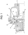
- Fig. 1 illustrates a part of a known variable nozzle turbocharger 10 including the.turbine housing 12 and the center housing 32.
- the turbine housing 12 has an exhaust gas inlet (not shown) for receiving an exhaust gas stream and an exhaust gas outlet 16 for directing exhaust gas to the exhaust system of the engine.
- a volute 14 connect the exhaust inlet and a nozzle which is defined between an insert 18 and a nozzle ring 28.
- the insert 18 forms an outer nozzle wall and is attached to the center housing 32 such that it is incorporated in the turbine housing 12 adjacent the volute 14.
- the nozzle ring 28 acts as an inner nozzle wall and is fitted into the insert 18.
- a turbine wheel 30 is carried within the exhaust gas outlet 16 of the turbine housing 12.
- Exhaust gas or other high energy gas supplying the turbocharger 10, enters the turbine wheel 30 through the exhaust gas inlet and is distributed through the volute 14 in the turbine housing 12 for substantially radial entry into the turbine wheel 30 through the circumferential nozzle defined by the insert 18 and the nozzle ring 28.
- vanes 20 are mounted to the nozzle ring 28 using vane pins 22 that project perpendicularly outwardly from the vanes 20.
- Each vane pin 22 is attached to a vane arm 24, and the vane arms 24 are received in a rotatably mounted unison ring 28.
- An actuator assembly is connected with the unison ring 26 and is configured to rotate the unison ring 26 in one direction or the other as necessary to move the vanes 20 radially, with respect to an axis of rotation of the turbine wheel 30, outwardly or inwardly to respectively increase or decrease the pressure differential and to modify the flow of exhaust gas through the turbine wheel 30.
- the vane arms 24 are caused to move, and the movement of the vane arms 24 causes the vanes 20 to pivot via rotation of the vane pins 24 and open or close a throat area of the nozzle depending on the rotational direction of the unison ring 26.
- the vanes are generally designed having an airfoil shape that is configured to both provide a complementary fit with adjacent vanes when placed in a closed position, and to provide for the passage of exhaust gas within the turbine housing to the turbine wheel when placed in an open position.
- a vane has a leading edge or nose having a first radius of curvature and a trailing edge or tail having a substantially smaller second radius of curvature connected by an inner airfoil surface on an inner side of the vane and an outer airfoil surface on an outer side of the vane.
- the outer airfoil surface is convex in shape
- the inner airfoil surface is convex in shape at the leading edge and concave in shape towards the trailing edge.
- the inner and outer airfoil surfaces are defined by a substantially continuous curve which complement each other.
- the vane surfaces are characterized as “concave” or “convex” relative to the interior (not the exterior) of the vane.
- the asymmetric shape of such a vane results in a curved centerline, which is also commonly referred to as the camberline of the vane.
- the camberline is the line that runs through the midpoints between the vane inner and outer airfoil surfaces between the leading and trailing edges of the vane. Its meaning is well understood by those skilled in the relevant technical field. Because this vane has a curved camberline, it is a "cambered" vane.
- variable nozzle turbocharger be provided with improved vane operational controllability when compared to conventional turbochargers.
- the inventors did extensive research to find the cause of torque reversion in a turbocharger with a variable nozzle assembly having a plurality of cambered vanes positioned annularly around a turbine wheel. They found that the predominant factors are: (a) the position of the vane pivot point, (b) the position of a local extreme of curvature in the convex section of the inner airfoil surface with respect to the pivot point, (c) the shape of the convex section of the inner airfoil surface, and (d) the flow incidence angle of exhaust gas on the vane surface.
- the convex section of the inner airfoil surface preferably has a somewhat longish shape. Therefore, it is favorable that in the above-mentioned coordinate system, the local extreme is located at a position which meets the following expression: 0.40 ⁇ Yex / Xex ⁇ 0.83 , wherein Xex is a distance between the local extreme and the leading edge on the x-axis, and Yex is a distance between the local extreme and the leading edge on the y-axis.
- the vane leading edge is defined by a circular curve having a radius r which meets the following expression: 0.045 ⁇ r / Xp ⁇ 0.08 , wherein Xp is a distance between the pivot point and the leading edge on the x-axis.
- the convex section of the inner airfoil surface is defined by a composite series of curves consisting of a circular curve that defines the leading edge and transitions into a parabolic curve, and optionally a circular or elliptic curve that connects the parabolic curve and the concave section.
- the outer airfoil surface is defined by a composite series of curves including a circular curve that defines the leading edge and transitions into an elliptic curve.
- a ratio Rle/Rte of a radius Rle tangent to the leading edges (Ple) of the vanes (20) to a radius Rte tangent to the trailing edges (Pte) ranges from 1.03 to 1.5.
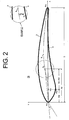
- Fig. 2 illustrates a cambered vane 20 according to a preferred embodiment of this invention.
- the cambered vane 20 according to this embodiment may be used in the variable nozzle turbocharger 10 shown in Fig. 1 .
- Other turbocharger layouts may be suitable as well.
- the cambered vane 20 comprises an outer airfoil surface 2 that is substantially convex in shape and that is defined by a composite series of curves, and an opposite inner airfoil surface 4 that includes convex and concave-shaped sections and that is also defined by a composite series of curves.
- a leading edge or nose Ple is located at one end of the vane between the inner and outer airfoil surfaces, and a trailing edge or tail Pte is located at an opposite end of the vane between the inner and outer airfoil surfaces.
- the leading edge Ple is defined by a circular curve having a first radius of curvature r (not shown), and the trailing edge Pte is defined by a circular curve preferably having a smaller second radius of curvature.
- the vane has a certain length which is defined as the length of the chord (straight line) C that runs between the leading and trailing vane edges Ple, Pte. Furthermore, the vane has a pivot point Pp, so it can rotate.
- the composite series of curves defining the outer airfoil surface 2 includes a section having the shape of a truncated ellipse for the first 10 or 20% of the vane length C and a section having a constant or decreasing radius of curvature for the rest of the vane length C.
- the composite series of curves defining the inner airfoil surface 4 includes a convex section that is defined by a second order polynomial for the first 20 to 30% of the vane length C and a concave section having a constant or increasing radius of curvature for almost the rest of the vane length C. The end of the convex section is marked by the inflection point.
- the convex section resembles a parabolic curve that potentially transitions into a short circular or elliptic curve connecting the parabolic curve and the concave section.
- the vertex of the parabolic curve defines a local extreme of curvature Pex.
- the midpoints between the inner and outer airfoil surfaces 2, 4 having the above shape define a curved camberline 6.
- the camberline is almost flat for the first 15 to 25% of the vane length C, at which point the camberline 6 becomes curved.
- the coordinate system shown in Fig. 2 is used for defining the positions of the pivot point Pp and the local extreme Pex.
- the origin of this coordinate system is the leading edge Ple.
- the x-axis coincides with the chord C that defines the vane length and runs between the leading and trailing vane edges Ple, Pte.
- the y-axis is normal to the x-axis and runs to the outer side of the vane in the direction in which the outer airfoil surface 2 extends.
- the pivot point Pp is located at a position which is defined by a distance Xp between the pivot point Pp and the leading edge Ple on the x-axis and a distance Yp between the pivot point Pp and the camberline 6 of the vane on the y-axis.
- Negative values of Yp represent a pivot point Pp which is closer to the inner airfoil surface 4 or the inner side of the vane (see example on the upper right of the drawing).
- the local extreme Pex is located at a position which is defined by a distance Xex between the leading edge Ple and the local extreme Pex on the x-axis and a distance Yex between the leading edge Ple and the local extreme Pex on the y-axis.
- a plurality of, for example, eleven vanes 20 is disposed in the turbine housing of the turbocharger, equally spaced and radially around a turbine wheel so as to form a variable exhaust nozzle assembly.
- the pivot point of each vane 20 is located on a radius Rp coaxial to a radial center 0 of the variable exhaust nozzle assembly.
- the vanes 20 pivot between a minimum and a maximum stagger angle ⁇ .
- the stagger angle ⁇ is defined between the chord C of the vane and a straight line running between the radial center 0 of the variable exhaust nozzle assembly and the pivot point Pp of the vane.
- the vanes 20 are in a closed position defining a minimum throat distance d between two adjacent vanes. At the minimum stagger angle ⁇ , the vanes 20 are in an open position defining a maximum throat distance d.
- the vane leading edges Ple define a first radius Rle and the vane trailing edges Pte define a second radius Rte which is smaller than the first radius Rle.
- the vanes 20 are disposed in the turbine housing such that that the inner airfoil surface 4 faces the exhaust gas stream.
- the flow incidence angle ⁇ of exhaust gas is defined with respect to a straight line running between the leading edge Ple and the pivot point Pp of the vane 20. Positive values of ⁇ tend to open the nozzle, while negative values of ⁇ tend to close the nozzle. Accordingly, the risk of an aerodynamic torque reversion affecting the controllability of the vanes 20 is the highest when the stagger angle ⁇ is high and the flow incidence angle ⁇ is small.
- the inventors prepared a large number of vanes having different vane profiles and investigated the influence of the vane profile on operational controllability and turbocharger operating efficiency by using flow analysis and other methods.
- the aerodynamic torque was measured at two stagger angles ⁇ near the minimum and maximum stagger angle, and the efficiency was measured at the minimum stagger angle where the throat distance d is maximum.
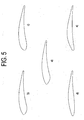
- Fig. 5 shows some examples of the vane profiles examined by the inventors. The following table gives details on the specifications. It is to be noted that Example a) is the same as the one shown in Fig. 2 . Table Example Xp/C Yp/C (Xp-Xex)/Xp Yex/Xex a) 0.35 0.00 0.56 0.50 b) 0.34 0.00 0.60 0.51 c) 0.36 0.00 0.44 0.19 d) 0.36 0.00 0.67 0.32 e) 0.37 0.00 0.94 1.04
- Example a) exhibited both excellent controllability and excellent efficiency when mounted in a turbocharger.
- the controllability of Example b) was as good as the controllability of Example a), but the efficiency, though still being good, was somewhat reduced.
- Example c) was best in controllability but exhibited only fair efficiency.
- Example d) was best in efficiency but controllability was not sufficient.
- Example e) had controllability as poor as Example d) and efficiency similar to Example c). It follows that Example a) corresponding to the vane shown in Fig. 2 is the best compromise between the needs for good controllability and good efficiency. However, Examples b) and c) meet the needs as well.
- the local extreme Pex is located at a position where the distance Xex between the local extreme Pex and the leading edge Ple on the x-axis meets the expression 0.3 ⁇ (Xp-Xex)/Xp ⁇ 0.8, preferably 0.4 ⁇ (Xp-Xex)/Xp ⁇ 0.7, and most preferably 0.49 ⁇ (Xp-Xex)/Xp ⁇ 0.60.
- the local extreme Pex is preferably located such that the convex section of the inner airfoil surface 2 has a somewhat longish shape.
- the local extreme is located at a position Xex, Yex where the respective distances Xex and Yex between the local extreme Pex and the leading edge Ple on the x-axis and the y-axis meet the expression 0.40 ⁇ Yex/Xex ⁇ 0.83.
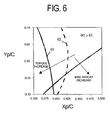
- the inventors prepared a number of vanes having the same shape as the vane 20 shown in Fig. 2 but having the pivot point Pp located at different positions Xp, Yp. Again, aerodynamic torque was measured at two stagger angles ⁇ 1 and ⁇ 2 near the minimum and maximum stagger angle, respectively, and efficiency was measured at the minimum stagger angle where the throat distance d is maximum. The results of these tests are shown in Fig. 6 .
- the left side of the two vertical lines corresponding to the stagger angles 01 and 02 defines the area of positive torque, and the lower right of the oblique curve the area of increasing maximum nozzle throat area. It follows that it is possible to achieve a desired positive torque if the distance Xp between the pivot point Pp and the leading edge Ple on the x-axis and the vane length C meet the expression Xp/C ⁇ 0.45. However, the smaller Xp/C is the smaller is the maximum nozzle throat area and thus the turbocharger and turbocharged engine operating efficiencies. Therefore, it is preferable that Xp/C is more than 0.25. More preferably, Xp and C meet the expression 0.30 ⁇ Xp/C ⁇ 0.40.
- Fig. 6 shows that the distance Yp between the pivot point Pp and the camberline 6 of the vane 8 on the y-axis has some impact on aerodynamic torque and efficiency as well.
- the pivot point Pp is located at a position meeting the expression -0.10 ⁇ Yp/C ⁇ 0.05, preferably -0.10 ⁇ Yp/C ⁇ 0, most preferably -0.10 ⁇ Yp/C ⁇ -0.05. Be that is it may, constructional requirements may be against locating the pivot point Pp outside the outer and inner airfoil surfaces 2, 4.
- the radius r defining the circular curve of the leading edge Ple and the distance Xp between the pivot point Pp and the leading edge Ple on the x-axis preferably meet the expression 0.045 ⁇ r/Xp ⁇ 0.08. Setting the radius r within this range reduces the sensitivity of the vane against variation of flow incidence.
- the shape of the convex section of the inner airfoil surface 4 is not restricted to a parabolic curve or a curve having a local maximum between the leading edge Ple and the inflection point marking the transition to the concave section, but that a second order polynomial having a local minimum is suitable as well. However, a local maximum is preferred.
Landscapes
- Engineering & Computer Science (AREA)
- Mechanical Engineering (AREA)
- General Engineering & Computer Science (AREA)
- Physics & Mathematics (AREA)
- Fluid Mechanics (AREA)
- Supercharger (AREA)
- Control Of Turbines (AREA)
Claims (12)
- Turbolader (10) mit einem variablen Turbinenaufbau, der eine Vielzahl von gewölbten Leitschaufeln (20) hat, die ringförmig um ein Turbinenrad (30) herum positioniert sind, wobei jede Leitschaufel (20) um einen Drehpunkt (Pp) herum drehbar ist und so gestaltet ist, dass sie eine Anströmkante (Ple) und eine Hinterkante (Pte) hat, die durch eine äußere Flügelprofilfläche (2) auf einer Außenseite der Leitschaufel (20) und eine innere Flügelprofilfläche (4) auf einer Innenseite der Leitschaufel (20) verbunden sind, wobei die äußere Flügelprofilfläche (2) im Wesentlichen konvex ist und die innere Flügelprofilfläche (4) an der Anströmkante (Ple) einen konvexen Bereich hat, der ein lokales Extrem (Pex) an Krümmung hat, und zur Hinterkante (Pte) hin in einen konkaven Bereich übergeht,
wobei sich in einem Koordinatensystem, in dem der Ursprung die Anströmkante (Ple) ist, die x-Achse durch die Hinterkante (Pte) läuft und die y-Achse zur x-Achse normal ist und zur Außenseite der Leitschaufel (20) läuft, der Drehpunkt (Pp) an einer Position befindet, die den folgenden Ausdruck erfüllt:
wobei Xp der Abstand zwischen dem Drehpunkt (Pp) und der Anströmkante (Ple) auf der x-Achse ist und C der Abstand zwischen der Anströmkante (Ple) und der Hinterkante (Pte) ist,
dadurch gekennzeichnet, dass
sich der Drehpunkt (Pp) an einer Position befindet, die den folgenden Ausdruck erfüllt:
wobei Yp der Abstand zwischen dem Drehpunkt (Pp) und einer Wölbungslinie (6) der Leitschaufel (20) auf der y-Achse ist, wobei negative Werte von Yp einen Drehpunkt (Pp) darstellen, der sich mehr auf der Innenseite der Leitschaufel (20) befindet. - Turbolader (10) nach Anspruch 1, wobei Yp derart eingestellt ist, dass sich der Drehpunkt (Pp) zwischen der äußeren Flügelprofilfläche (2) und der inneren Flügelprofilfläche (4) befindet.
- Turbolader (10) nach Anspruch 1 oder 2, wobei sich das lokale Extrem (Pex) an einer Position befindet, die den folgenden Ausdruck erfüllt:

wobei Xex ein Abstand zwischen dem lokalen Extrem (Pex) und der Anströmkante (Ple) auf der x-Achse ist. - Turbolader (10) nach einem vorstehenden Anspruch, wobei sich das lokale Extrem (Pex) an einer Position befindet, die den folgenden Ausdruck erfüllt:

wobei Xex ein Abstand zwischen dem lokalen Extrem (Pex) und der Anströmkante (Ple) auf der x-Achse ist und Yex ein Abstand zwischen dem lokalen Extrem (Pex) und der Anströmkante (Ple) auf der y-Achse ist. - Turbolader (10) nach einem vorstehenden Anspruch, wobei das lokale Extrem (Pex) ein lokales Maximum ist.
- Turbolader (10) nach einem vorstehenden Anspruch, wobei, wenn die Leitschaufeln (20) in einer geschlossenen Position platziert sind, ein Strömungsauftreffwinkel (α) von Abgas bezüglich einer die Anströmkante (Ple) und den Drehpunkt (Pp) verbindenden Linie 5° oder mehr beträgt.
- Turbolader (10) mit einem variablen Turbinenaufbau, der eine Vielzahl von gewölbten Leitschaufeln (20) hat, die ringförmig um ein Turbinenrad (30) herum positioniert sind, wobei jede Leitschaufel (20) um einen Drehpunkt (Pp) herum drehbar ist und so gestaltet ist, dass sie eine Anströmkante (Ple) und eine Hinterkante (Pte) hat, die durch eine äußere Flügelprofilfläche (2) auf einer Außenseite der Leitschaufel (20) und eine innere Flügelprofilfläche (4) auf einer Innenseite der Leitschaufel (20) verbunden sind, wobei die äußere Flügelprofilfläche (2) im Wesentlichen konvex ist, und dadurch gekennzeichnet, dass die innere Flügelprofilfläche (4) an der Anströmkante (Ple) einen konvexen Bereich hat, der ein lokales Maximum (Pex) an Krümmung hat, und zur Hinterkante (Pte) hin in einen konkaven Bereich übergeht und
sich in einem Koordinatensystem, in dem der Ursprung die Anströmkante (Ple) ist, die x-Achse durch die Hinterkante (Pte) läuft und die y-Achse zur x-Achse normal ist und zur Außenseite der Leitschaufel (20) läuft, das lokale Maximum (Pex) an einer Position befindet, die den folgenden Ausdruck erfüllt:
wobei Xp ein Abstand zwischen dem Drehpunkt (Pp) und der Anströmkante (Ple) auf der x-Achse ist und (Xex) ein Abstand zwischen dem lokalen Maximum (Pex) und der Anströmkante (Ple) auf der x-Achse ist. - Turbolader (10) mit einem variablen Turbinenaufbau, der eine Vielzahl von gewölbten Leitschaufeln (20) hat, die ringförmig um ein Turbinenrad (30) herum positioniert sind, wobei jede Leitschaufel (20) um einen Drehpunkt (Pp) herum drehbar ist und so gestaltet ist, dass sie eine Anströmkante (Ple) und eine Hinterkante (Pte) hat, die durch eine äußere Flügelprofilfläche (2) auf einer Außenseite der Leitschaufel (20) und eine innere Flügelprofilfläche (4) auf einer Innenseite der Leitschaufel (20) verbunden sind, wobei die äußere Flügelprofilfläche (2) im Wesentlichen konvex ist, und dadurch gekennzeichnet, dass die innere Flügelprofilfläche (4) an der Anströmkante (Ple) einen konvexen Bereich hat, der ein lokales Maximum (Pex) an Krümmung hat, und zur Hinterkante (Pte) hin in einen konkaven Bereich übergeht und
sich in einem Koordinatensystem, in dem der Ursprung die Anströmkante (Ple) ist, die x-Achse durch die Hinterkante (Pte) läuft und die y-Achse zur x-Achse normal ist und zur Außenseite der Leitschaufel (20) läuft, das lokale Maximum (Pex) an einer Position befindet, die den folgenden Ausdruck erfüllt:
wobei Xex ein Abstand zwischen dem lokalen Maximum (Pex) und der Anströmkante (Ple) auf der x-Achse ist und Yex ein Abstand zwischen dem lokalen Maximum (Pex) und der Anströmkante (Ple) auf der y-Achse ist. - Turbolader (10) nach einem vorstehenden Anspruch, wobei die Anströmkante (Ple) durch eine kreisförmige Kurve mit einem Radius r definiert ist, der den folgenden Ausdruck erfüllt:

wobei Xp ein Abstand zwischen dem Drehpunkt (Pp) und der Anströmkante (Ple) auf der x-Achse ist. - Turbolader (10) nach einem vorstehenden Anspruch, wobei der konvexe Bereich der inneren Flügelprofilfläche (4) durch eine zusammengesetzte Reihe von Kurven definiert ist, die aus einer kreisförmigen Kurve, die die Anströmkante (Ple) definiert und in eine parabolische Kurve übergeht, und optional einer kreisförmigen oder elliptischen Kurve besteht, die die parabolische Kurve und den konkaven Bereich verbindet.
- Turbolader (10) nach einem vorstehenden Anspruch, wobei die äußere Flügelprofilfläche (2) durch eine zusammengesetzte Reihe von Kurven definiert ist, die eine kreisförmige Kurve enthält, die die Anströmkante (Ple) definiert und in eine elliptische Kurve übergeht.
- Turbolader (10) nach einem vorstehenden Anspruch, wobei, wenn sich die Leitschaufeln (20) zwischen einer geschlossenen Position und einer offenen Position drehen, ein Verhältnis Rle/Rte eines Radius Rle tangential zu den Anströmkanten (Ple) der Leitschaufeln (20) zu einem Radius Rte tangential zu den Hinterkanten (Pte) von 1.03 bis 1.5 reicht.
Applications Claiming Priority (1)
| Application Number | Priority Date | Filing Date | Title |
|---|---|---|---|
| PCT/EP2004/012992 WO2006053579A1 (en) | 2004-11-16 | 2004-11-16 | Variable nozzle turbocharger |
Publications (3)
| Publication Number | Publication Date |
|---|---|
| EP1797283A1 EP1797283A1 (de) | 2007-06-20 |
| EP1797283B1 true EP1797283B1 (de) | 2013-12-18 |
| EP1797283B2 EP1797283B2 (de) | 2017-11-29 |
Family
ID=34959456
Family Applications (1)
| Application Number | Title | Priority Date | Filing Date |
|---|---|---|---|
| EP04797934.9A Expired - Lifetime EP1797283B2 (de) | 2004-11-16 | 2004-11-16 | Turbolader mit leitschaufeln variabler geometrie |
Country Status (5)
| Country | Link |
|---|---|
| US (1) | US8109715B2 (de) |
| EP (1) | EP1797283B2 (de) |
| JP (1) | JP2008520881A (de) |
| CN (1) | CN101103178B (de) |
| WO (1) | WO2006053579A1 (de) |
Cited By (3)
| Publication number | Priority date | Publication date | Assignee | Title |
|---|---|---|---|---|
| EP3073063A1 (de) | 2015-03-23 | 2016-09-28 | Bosch Mahle Turbo Systems GmbH & Co. KG | Ladeeinrichtung und zugehörige leitschaufel |
| US11333034B2 (en) | 2018-11-13 | 2022-05-17 | Mitsubishi Heavy Industries Engine & Turbocharger, Ltd. | Nozzle vane |
| US11428154B2 (en) | 2018-12-19 | 2022-08-30 | Mitsubishi Heavy Industries Engine & Turbocharger, Ltd. | Nozzle vane |
Families Citing this family (25)
| Publication number | Priority date | Publication date | Assignee | Title |
|---|---|---|---|---|
| EP3150805B1 (de) * | 2005-11-25 | 2020-09-23 | BorgWarner, Inc. | Schaufel eines turboladers mit verstellbarer turbinengeometrie sowie turbolader |
| DE102008004014A1 (de) * | 2008-01-11 | 2009-07-23 | Continental Automotive Gmbh | Leitschaufel für eine variable Turbinengeometrie |
| JP5201333B2 (ja) * | 2008-03-11 | 2013-06-05 | 株式会社Ihi | 可変ノズルのベーン形状及び可変容量過給機 |
| DE102009006209B4 (de) * | 2009-01-27 | 2022-12-01 | BMTS Technology GmbH & Co. KG | Ladeeinrichtung mit variabler Turbinengeometrie |
| DE102009014004A1 (de) * | 2009-03-19 | 2010-09-23 | Bosch Mahle Turbo Systems Gmbh & Co. Kg | Turbolader und zugehörige Leitschaufel |
| DE102009036406A1 (de) * | 2009-08-06 | 2011-02-10 | Mtu Aero Engines Gmbh | Schaufelblatt |
| DE102009041027B4 (de) * | 2009-09-14 | 2012-02-09 | Continental Automotive Gmbh | Leitschaufel für einen Turbolader, Leitschaufelanordnung, Turbolader, Kraftfahrzeug und Verfahren |
| US8393872B2 (en) * | 2009-10-23 | 2013-03-12 | General Electric Company | Turbine airfoil |
| US8834104B2 (en) * | 2010-06-25 | 2014-09-16 | Honeywell International Inc. | Vanes for directing exhaust to a turbine wheel |
| JP5866802B2 (ja) | 2011-05-26 | 2016-02-17 | 株式会社Ihi | ノズル翼 |
| FR2976018B1 (fr) * | 2011-06-01 | 2014-12-05 | Turbomeca | Distributeur de turbine radiale a calage variable, en particulier de turbine de source de puissance auxiliaire |
| GB201119531D0 (en) * | 2011-11-14 | 2011-12-21 | Rolls Royce Plc | Aerofoils |
| JP5964081B2 (ja) * | 2012-02-29 | 2016-08-03 | 三菱重工業株式会社 | 可変容量ターボチャージャ |
| US9957969B2 (en) | 2012-06-19 | 2018-05-01 | Volvo Lastvagnar Ab | Device for controlling a gas flow, an exhaust aftertreatment system and a system for propelling a vehicle |
| JP6225515B2 (ja) * | 2013-07-05 | 2017-11-08 | 株式会社Ihi | 可変ノズルユニット及び可変容量型過給機 |
| DE102013224572A1 (de) * | 2013-11-29 | 2015-06-03 | Bosch Mahle Turbo Systems Gmbh & Co. Kg | Abgasturbolader, insbesondere für ein Kraftfahrzeug |
| GB2523133B (en) * | 2014-02-13 | 2016-06-01 | X-Wind Power Ltd | Vertical axis wind turbine rotor and aerofoil |
| DE102015006458A1 (de) | 2015-05-20 | 2015-12-03 | Daimler Ag | Leitschaufel für einen Diffusor eines Radialverdichters |
| CN105387893B (zh) * | 2015-12-11 | 2020-02-11 | 罗美特(上海)自动化仪表股份有限公司 | 一种涡轮流量计的叶轮结构及其涡轮流量计 |
| WO2018084154A1 (ja) * | 2016-11-01 | 2018-05-11 | 株式会社Ihi | 可変ノズルユニットおよび過給機 |
| US10392961B2 (en) | 2017-05-18 | 2019-08-27 | Ford Global Technologies, Llc | Nozzle blade design for a variable nozzle turbine |
| US20190063254A1 (en) * | 2017-08-31 | 2019-02-28 | GM Global Technology Operations LLC | Turbocharger utilizing variable-camber turbine guide vane system |
| CN108952825B (zh) * | 2018-06-22 | 2021-11-16 | 苏州诺迅汽车部件有限公司 | 一种用于喷嘴环的叶片组件 |
| CN109578085B (zh) * | 2018-12-26 | 2021-06-22 | 中国船舶重工集团公司第七0三研究所 | 一种通过导叶倾斜减弱涡轮动叶非定常作用力的方法 |
| GB2592446A (en) | 2020-02-28 | 2021-09-01 | Cummins Ltd | Variable geometry turbine |
Family Cites Families (12)
| Publication number | Priority date | Publication date | Assignee | Title |
|---|---|---|---|---|
| US4629396A (en) | 1984-10-17 | 1986-12-16 | Borg-Warner Corporation | Adjustable stator mechanism for high pressure radial turbines and the like |
| US5299909A (en) * | 1993-03-25 | 1994-04-05 | Praxair Technology, Inc. | Radial turbine nozzle vane |
| CN1074511C (zh) * | 1994-12-28 | 2001-11-07 | 株式会社荏原制作所 | 具有可变角度导流装置的涡轮机械 |
| US5564895A (en) | 1995-04-26 | 1996-10-15 | Rotoflow Corporation | Active automatic clamping control |
| GB0025244D0 (en) * | 2000-10-12 | 2000-11-29 | Holset Engineering Co | Turbine |
| US6419464B1 (en) | 2001-01-16 | 2002-07-16 | Honeywell International Inc. | Vane for variable nozzle turbocharger |
| DE10153301B4 (de) | 2001-10-31 | 2010-09-23 | Daimler Ag | Abgasturbolader für eine Brennkraftmaschine |
| JP3605398B2 (ja) * | 2002-02-26 | 2004-12-22 | 三菱重工業株式会社 | 可変容量ターボチャージャ |
| US6755612B2 (en) * | 2002-09-03 | 2004-06-29 | Rolls-Royce Plc | Guide vane for a gas turbine engine |
| US6709232B1 (en) * | 2002-09-05 | 2004-03-23 | Honeywell International Inc. | Cambered vane for use in turbochargers |
| WO2005064121A1 (en) * | 2003-12-31 | 2005-07-14 | Honeywell International, Inc. | Cambered vane for use in turbochargers |
| DE102004044324A1 (de) | 2004-09-10 | 2006-03-16 | Bayerische Motoren Werke Ag | Abgasturbolader |
-
2004
- 2004-11-16 US US11/667,799 patent/US8109715B2/en active Active
- 2004-11-16 EP EP04797934.9A patent/EP1797283B2/de not_active Expired - Lifetime
- 2004-11-16 WO PCT/EP2004/012992 patent/WO2006053579A1/en not_active Ceased
- 2004-11-16 CN CN2004800448224A patent/CN101103178B/zh not_active Expired - Lifetime
- 2004-11-16 JP JP2007541695A patent/JP2008520881A/ja active Pending
Cited By (4)
| Publication number | Priority date | Publication date | Assignee | Title |
|---|---|---|---|---|
| EP3073063A1 (de) | 2015-03-23 | 2016-09-28 | Bosch Mahle Turbo Systems GmbH & Co. KG | Ladeeinrichtung und zugehörige leitschaufel |
| DE102015205208A1 (de) | 2015-03-23 | 2016-09-29 | Bosch Mahle Turbo Systems Gmbh & Co. Kg | Ladeeinrichtung mit variabler Turbinengeometrie |
| US11333034B2 (en) | 2018-11-13 | 2022-05-17 | Mitsubishi Heavy Industries Engine & Turbocharger, Ltd. | Nozzle vane |
| US11428154B2 (en) | 2018-12-19 | 2022-08-30 | Mitsubishi Heavy Industries Engine & Turbocharger, Ltd. | Nozzle vane |
Also Published As
| Publication number | Publication date |
|---|---|
| US8109715B2 (en) | 2012-02-07 |
| CN101103178A (zh) | 2008-01-09 |
| US20080131267A1 (en) | 2008-06-05 |
| CN101103178B (zh) | 2010-09-29 |
| JP2008520881A (ja) | 2008-06-19 |
| EP1797283A1 (de) | 2007-06-20 |
| EP1797283B2 (de) | 2017-11-29 |
| WO2006053579A1 (en) | 2006-05-26 |
Similar Documents
| Publication | Publication Date | Title |
|---|---|---|
| EP1797283B1 (de) | Turbolader mit leitschaufeln variabler geometrie | |
| US6709232B1 (en) | Cambered vane for use in turbochargers | |
| EP1714008B1 (de) | Abgasturbolader | |
| US8123471B2 (en) | Variable stator vane contoured button | |
| US7758306B2 (en) | Turbine assembly for a gas turbine engine and method of manufacturing the same | |
| CA2495186C (en) | Recirculation structure for turbocompressors | |
| EP2716878B1 (de) | Turbolader mit verstellbarer Leistungsfähigkeit mit Eintrittsleitschaufeln | |
| EP1904730B1 (de) | Turbolader mit variabler düse | |
| US10927849B2 (en) | Apparatus for transferring energy between a rotating element and fluid | |
| CN110121599A (zh) | 离心压缩机、涡轮增压器 | |
| US10914190B2 (en) | Variable nozzle unit and turbocharger | |
| EP3161323B1 (de) | Einlassleitschaufelsystem | |
| US7794201B2 (en) | Gas turbine engines including lean stator vanes and methods of assembling the same | |
| US11047256B2 (en) | Variable nozzle unit and turbocharger | |
| JP4436346B2 (ja) | 可変容量タービン及びこれを備えた可変容量ターボチャージャ | |
| CN216618021U (zh) | 一种自适应缝隙调节可变弯度进口导叶 | |
| JP3905811B2 (ja) | 可変容量タービン及びこれを備えた可変容量ターボチャージャ | |
| KR20070085560A (ko) | 가변 노즐 터보차저 | |
| CN115176071A (zh) | 可变几何涡轮机 | |
| CN109312659A (zh) | 涡轮增压器、涡轮增压器的喷嘴叶片以及涡轮机 |
Legal Events
| Date | Code | Title | Description |
|---|---|---|---|
| PUAI | Public reference made under article 153(3) epc to a published international application that has entered the european phase |
Free format text: ORIGINAL CODE: 0009012 |
|
| 17P | Request for examination filed |
Effective date: 20070323 |
|
| AK | Designated contracting states |
Kind code of ref document: A1 Designated state(s): DE FR GB |
|
| DAX | Request for extension of the european patent (deleted) | ||
| RBV | Designated contracting states (corrected) |
Designated state(s): DE FR GB |
|
| 17Q | First examination report despatched |
Effective date: 20080404 |
|
| GRAP | Despatch of communication of intention to grant a patent |
Free format text: ORIGINAL CODE: EPIDOSNIGR1 |
|
| INTG | Intention to grant announced |
Effective date: 20130705 |
|
| GRAS | Grant fee paid |
Free format text: ORIGINAL CODE: EPIDOSNIGR3 |
|
| GRAA | (expected) grant |
Free format text: ORIGINAL CODE: 0009210 |
|
| AK | Designated contracting states |
Kind code of ref document: B1 Designated state(s): DE FR GB |
|
| REG | Reference to a national code |
Ref country code: GB Ref legal event code: FG4D |
|
| REG | Reference to a national code |
Ref country code: DE Ref legal event code: R096 Ref document number: 602004044035 Country of ref document: DE Effective date: 20140213 |
|
| REG | Reference to a national code |
Ref country code: DE Ref legal event code: R026 Ref document number: 602004044035 Country of ref document: DE |
|
| PLBI | Opposition filed |
Free format text: ORIGINAL CODE: 0009260 |
|
| PLBI | Opposition filed |
Free format text: ORIGINAL CODE: 0009260 |
|
| 26 | Opposition filed |
Opponent name: BOSCH MAHLE TURBO SYSTEMS GMBH & CO. KG Effective date: 20140916 |
|
| 26 | Opposition filed |
Opponent name: BORGWARNER, INC. Effective date: 20140918 |
|
| PLAX | Notice of opposition and request to file observation + time limit sent |
Free format text: ORIGINAL CODE: EPIDOSNOBS2 |
|
| REG | Reference to a national code |
Ref country code: DE Ref legal event code: R026 Ref document number: 602004044035 Country of ref document: DE Effective date: 20140916 |
|
| PLBB | Reply of patent proprietor to notice(s) of opposition received |
Free format text: ORIGINAL CODE: EPIDOSNOBS3 |
|
| PLAB | Opposition data, opponent's data or that of the opponent's representative modified |
Free format text: ORIGINAL CODE: 0009299OPPO |
|
| R26 | Opposition filed (corrected) |
Opponent name: BORGWARNER, INC. Effective date: 20140918 |
|
| PLAB | Opposition data, opponent's data or that of the opponent's representative modified |
Free format text: ORIGINAL CODE: 0009299OPPO |
|
| R26 | Opposition filed (corrected) |
Opponent name: BORGWARNER, INC. Effective date: 20140918 |
|
| REG | Reference to a national code |
Ref country code: FR Ref legal event code: PLFP Year of fee payment: 12 |
|
| RAP2 | Party data changed (patent owner data changed or rights of a patent transferred) |
Owner name: HONEYWELL INTERNATIONAL INC. |
|
| REG | Reference to a national code |
Ref country code: FR Ref legal event code: PLFP Year of fee payment: 13 |
|
| APAH | Appeal reference modified |
Free format text: ORIGINAL CODE: EPIDOSCREFNO |
|
| APBM | Appeal reference recorded |
Free format text: ORIGINAL CODE: EPIDOSNREFNO |
|
| APBP | Date of receipt of notice of appeal recorded |
Free format text: ORIGINAL CODE: EPIDOSNNOA2O |
|
| APBU | Appeal procedure closed |
Free format text: ORIGINAL CODE: EPIDOSNNOA9O |
|
| PUAH | Patent maintained in amended form |
Free format text: ORIGINAL CODE: 0009272 |
|
| STAA | Information on the status of an ep patent application or granted ep patent |
Free format text: STATUS: PATENT MAINTAINED AS AMENDED |
|
| REG | Reference to a national code |
Ref country code: FR Ref legal event code: PLFP Year of fee payment: 14 |
|
| 27A | Patent maintained in amended form |
Effective date: 20171129 |
|
| AK | Designated contracting states |
Kind code of ref document: B2 Designated state(s): DE FR GB |
|
| REG | Reference to a national code |
Ref country code: DE Ref legal event code: R102 Ref document number: 602004044035 Country of ref document: DE |
|
| REG | Reference to a national code |
Ref country code: DE Ref legal event code: R081 Ref document number: 602004044035 Country of ref document: DE Owner name: GARRETT TRANSPORTATION I INC., TORRANCE, US Free format text: FORMER OWNER: HONEYWELL INTERNATIONAL INC., MORRISTOWN, N.J., US |
|
| REG | Reference to a national code |
Ref country code: GB Ref legal event code: 732E Free format text: REGISTERED BETWEEN 20190725 AND 20190731 |
|
| PGFP | Annual fee paid to national office [announced via postgrant information from national office to epo] |
Ref country code: GB Payment date: 20221122 Year of fee payment: 19 Ref country code: FR Payment date: 20221122 Year of fee payment: 19 Ref country code: DE Payment date: 20221128 Year of fee payment: 19 |
|
| REG | Reference to a national code |
Ref country code: DE Ref legal event code: R119 Ref document number: 602004044035 Country of ref document: DE |
|
| GBPC | Gb: european patent ceased through non-payment of renewal fee |
Effective date: 20231116 |
|
| PG25 | Lapsed in a contracting state [announced via postgrant information from national office to epo] |
Ref country code: DE Free format text: LAPSE BECAUSE OF NON-PAYMENT OF DUE FEES Effective date: 20240601 |
|
| PG25 | Lapsed in a contracting state [announced via postgrant information from national office to epo] |
Ref country code: GB Free format text: LAPSE BECAUSE OF NON-PAYMENT OF DUE FEES Effective date: 20231116 |
|
| PG25 | Lapsed in a contracting state [announced via postgrant information from national office to epo] |
Ref country code: FR Free format text: LAPSE BECAUSE OF NON-PAYMENT OF DUE FEES Effective date: 20231130 |
|
| PG25 | Lapsed in a contracting state [announced via postgrant information from national office to epo] |
Ref country code: GB Free format text: LAPSE BECAUSE OF NON-PAYMENT OF DUE FEES Effective date: 20231116 Ref country code: FR Free format text: LAPSE BECAUSE OF NON-PAYMENT OF DUE FEES Effective date: 20231130 Ref country code: DE Free format text: LAPSE BECAUSE OF NON-PAYMENT OF DUE FEES Effective date: 20240601 |