EP1795635A1 - Heald for warp yarns having a band shape - Google Patents
Heald for warp yarns having a band shape Download PDFInfo
- Publication number
- EP1795635A1 EP1795635A1 EP05026813A EP05026813A EP1795635A1 EP 1795635 A1 EP1795635 A1 EP 1795635A1 EP 05026813 A EP05026813 A EP 05026813A EP 05026813 A EP05026813 A EP 05026813A EP 1795635 A1 EP1795635 A1 EP 1795635A1
- Authority
- EP
- European Patent Office
- Prior art keywords
- thread
- heald
- heddle
- eye
- thread eye
- Prior art date
- Legal status (The legal status is an assumption and is not a legal conclusion. Google has not performed a legal analysis and makes no representation as to the accuracy of the status listed.)
- Granted
Links
Images


Classifications
-
- D—TEXTILES; PAPER
- D03—WEAVING
- D03C—SHEDDING MECHANISMS; PATTERN CARDS OR CHAINS; PUNCHING OF CARDS; DESIGNING PATTERNS
- D03C9/00—Healds; Heald frames
- D03C9/02—Healds
- D03C9/024—Eyelets
-
- D—TEXTILES; PAPER
- D03—WEAVING
- D03C—SHEDDING MECHANISMS; PATTERN CARDS OR CHAINS; PUNCHING OF CARDS; DESIGNING PATTERNS
- D03C9/00—Healds; Heald frames
- D03C9/02—Healds
-
- D—TEXTILES; PAPER
- D03—WEAVING
- D03D—WOVEN FABRICS; METHODS OF WEAVING; LOOMS
- D03D41/00—Looms not otherwise provided for, e.g. for weaving chenille yarn; Details peculiar to these looms
- D03D41/008—Looms for weaving flat yarns
Definitions
- the invention relates to a heddle, which is adapted for processing warp threads, which are formed in the manner of ribbons.
- looms which have at least one, but usually many so-called heald shanks for shedding.
- Each weave is formed by a substantially rectangular frame made vertically arranged side supports and an upper and a lower spar, the so-called shaft rod exists.
- Litzentragschienen are held on the shaft rods, which are usually formed by elongated steel rails with a rectangular cross-section. The steel rails are used to hold healds.
- Each heald has end loops for threading onto the top and bottom steel rails. Between the end eyelets of the heddle body extends. Approximately in the middle a thread eye is provided, through which the warp thread leads. If the shaft rod is moved upwards or downwards, all warp threads leading through the thread eyes of the strands are guided out of the warp thread bundle upwards or downwards, so that a shed is formed.
- the FR 394 156 discloses such a heddle made of flat strip steel.
- the flat sides of the steel strip are oriented in warp direction.
- the heald is compressed and punched in the area of the same.
- the resulting thread eye has a height measured in the vertical direction which is greater than the width measured in the horizontal direction.
- the thread eye is oriented in warp direction.
- the DE-PS 22996 discloses a heddle with warp-oriented yarn eye.
- the heald consists of two layers of thin metal strips that lie parallel to each other. In the area of the thread eye the metal strips are arched away from each other.
- the heddle is wound around its longitudinal direction, so that the thread eye is oriented transversely to the end eyelets.
- the presented healds are suitable for processing substantially round threads.
- ribbon-shaped fiber arrangements for example, polyester, aramid or carbon fiber band-shaped thread arrangements are to be processed, e.g. for producing fabrics for reinforcing highly stressed composite structures.
- the demand arises that the band-shaped fiber bundle retains its band-shaped structure in the weaving process, and e.g. aligned parallel to the tissue plane.
- the thread eye at its upper and lower Edge to be provided with a thread guide surface, the thread inlet side and / or yarn outlet side is rounded, wherein the extending in the warp direction length of this yarn guide is greater than the thickness of the strand body to be measured in the same direction.
- the heddle body can be made relatively thin and, for example, consist of sufficiently strong steel. The risk that form sharp edges on the thread eye, which can damage sensitive threads is banned by the inventively provided Fadenleit Structure. The thickness of the heald can thus be reduced to a minimum, which reduces the weight of the strands and thus the material costs and on the other hand increases the possible achievable working speed.
- the heald is rotated at least in the region of the thread eye transversely to the warp thread, i. the flat sides of the heald lie in a plane which also contains the two heddle rails or encloses with them an at least very acute angle near 0 °.
- This ensures that the opening direction of the thread eye substantially coincides with the running direction of the warp thread.
- the minimum thread eye width is made possible for the required opening width of the thread eye.
- a first heald is moved down to the lower position and a second heald up to the upper position. Both heddles have healds according to the invention, through the thread eye of which warp threads run.
- the warp thread of the first heald passes through a thread eye of a strand in the first heald in the lower region, wherein the warp thread of the second heald passes through a thread eye a strand of the second heald in the upper region.
- the two shafts change their position.
- the first weaving shaft goes up, at the same time the second weaving shaft goes down.
- the heddles also change the positions of the heddles and thus the warp threads or warp thread bundles passing through the thread eyes of the heddles.
- the warp thread passing through the thread eye of the first heald passes the outer edge of the adjacent heald of the second web shaft.
- the thread eye of a strand according to the invention is rotated transversely to the warp thread, the area between the outer edge of the strand and the thread eye can be made very small.
- This provides a warp thread of an adjacent strand of an adjacent heald shaft when changing position enough space to pass freely on the edge of the heald of the adjacent heald shaft over.
- the risk of injury to warp threads when changing position is greatly reduced.
- the formation of close-meshed tissues is possible.
- the formation of close-meshed fabrics may serve a slight inclination of the strand body in the region of the thread eye, whereby the opening direction the thread eye is inclined at an acute angle of a few degrees against the plane mentioned in claim 3.
- the heddle body is made of a band-shaped material, e.g. a steel band. At least on his thread eye he can be oriented transversely to the warp. The twist between the thread eye and the end eyelets is preferably 90 °.
- a band-shaped material e.g. a steel band.
- the Endulate can be formed by a separate, connected to the heald body element. Preferably, however, it is an integral part of the strand body, i. It is made of the same material as this one and goes seamlessly and seamlessly into it.
- the heald can thereby be produced as a simple punched body.
- the end eyelet may have any known shape such as the so-called O-shape, C-shape or J-shape or any future developed form.
- the end eyelets are formed by projections which are attached to the heald body and protrude over the flat side.
- the projections can be formed for example by tongues, which are cut free from the heald body and bent out laterally.
- the projections may also be formed by subsequently attached to the flat side of the strand body elements.
- Such elements may be, for example, by laser welding or riveted metal tabs, wherein the weld can be made longitudinally or transversely to the longitudinal direction of the strand body.
- the version with longitudinally oriented weld leads to a particularly high stability of the end eyelet thus formed.
- Fadenleit vom which may be formed for example by tabs that are bent out of the thread eye.
- the released tabs are bent out of the thread eye by at least 110 °. This results in generously dimensioned yarn guide surfaces, which can be used to weave brittle, break-sensitive threads.
- the Fadenleit vom on separate elements which are connected to the strand body. They thus form the upper and / or the lower edge of the thread eye.
- the separate elements may be made of hardened steel, carbide, plastic or ceramic.
- the elements can be connected to the strand body by gluing, soldering or welding.
- cemented carbide or ceramic allows interweaving particularly aggressive tapes, such as aramid fibers.
- the additional elements may also be provided with portions which protect at least a portion of the lateral flanks of the thread eye. This is achieved, for example, by having the elements in the form of a pin or disk end pin.
- the elements clearly project beyond the upper and lower edges of the thread eye.
- the elements are in the form of smaller, arranged on the flat sides of the strand body platelets whose edges are well rounded. These plates are attached to the front and back flat side of the strand body and lay according to their positioning, the height of the thread eye in the longitudinal direction of the strand. With this measure, thread eyes of different height can be realized on uniformly punched strand bodies, so that the respective strands can be set up for different band-shaped warp threads.
- FIG. 1 shows a heddle 1 for flat, band-shaped, not further illustrated warp threads.
- the heald 1 belongs to a group of the same or similarly formed healds, which are held on a heald, as it is used for shedding on a weaving machine.
- the heald 1 is mounted on two Litzentragschienen 2, 2 ', which are held at a distance parallel to each other at the upper and lower shaft rod of a heald.
- the heald 1 has a main body 3 consisting of strips of sheet steel, whose longitudinal direction 4 in FIG. 1 is oriented vertically and at a right angle to the heddle support rails 2, 2 '.
- end eyelets 5, 6, which can be formed in the simplest case by punched into the body 3 openings whose shape and size with a corresponding play addition to the cross section of the Litzentragschienen 2, 2 'corresponds.
- the main body 3 is provided with a thread eye 7, which serves to receive a warp thread.
- the thread eye 7 has, as can be seen in particular Figure 2, a substantially rectangular cross section, wherein its lateral edges 8, 9, which extend in the longitudinal direction 4, are shorter than its upper and its lower edge 10, 11, the transverse to the longitudinal direction 4 stand.
- the thread eye 7 is surrounded by a flat, essentially flat region 12, which lies at least approximately in or parallel to a plane defined by the heddle support rails 2, 2 '.
- the heddle 1 between the region 12 and the respective end eyelet 6, 7 respectively wound at points 13, 14 about 90 ° about the longitudinal direction 4.
- the heddle body is formed integrally from a relatively thin flat material made of metal, for example steel as a pure stamped and bent part.
- the width of the heddle body 3 is at least at the area 12, but preferably greater overall than the illustrated in Figure 2 width B of the thread eye 7.
- On both sides of the thread eye 7 remain webs 15, 16th , whose width is preferably slightly larger than the thickness of the sheet material from which the heald 1 is formed.
- the height H of the thread eye 7 to be measured in the longitudinal direction 4 is significantly smaller than its width B.
- the thread eye 7 can also be shaped oval or otherwise, deviating from the rectangular shape illustrated in FIG. 2, but in each case its width B is greater than its height H. is.
- the upper and lower edges 10, 11 are preferably formed by thread guide surfaces 17, 18, which, as shown in Figure 2, can connect directly to the flat sides of the region 12. However, the transitions may be rounded to save delicate warp threads 36.
- the warp threads 36 may each be formed by individual threads or strips (e.g., plastic tapes) or each of a plurality of interconnected or unjoined threads, a group of threads or a thread band 36.
- the regions 12 of the healds 1 are not rotated by exactly 90 ° against the end eyes 5, 6.
- the healds 1 of the first and second heald can thereby slightly overlap, whereby denser tissues can be produced.
- the existing from the viewpoint of the warp 36 clear width is at least slightly greater than the width of the flat warp 36th
- heald 1 slightly asymmetrical, either by the openings of the end eyelets 5, 6 are eccentrically punched into the heald body 3 or by the twisted areas or the rotation areas 13, 14 are bent somewhat asymmetrically.
- FIG. 3a and 3b illustrate a modified embodiment of the heald 1, to which the above explanation applies, with the exception of subsequent modifications and additions accordingly.
- the thread eye 7 is in turn formed substantially rectangular. However, it will initially, as illustrated in Figure 3a, punched in an H-shape so as to free upper and lower flaps 19, 20 which extend toward one another. The flaps 19, 20 are then bent away from each other as illustrated in FIG. 3b. You can, as shown, are bent out of the thread eye 7 to the same side or in opposite directions out and form a wedge-shaped or funnel-shaped thread eye. Preferably, they are bent by an angle that is significantly greater than 90 °. The preferred embodiments use angles ⁇ between 110 ° and 150 °.
- the tabs 19, 20 can be oriented in the thread running direction or against the running direction of the warp threads 36.
- thread guide surfaces 17, 18 are formed, which, as can be seen in FIG. 3b, start on a flat side 21 of the region 12 and extend in each case as far as the free end 22, 23 of each lobe 19, 20.
- the corresponding length to be measured is thus greater than the thickness of the strand body 3.
- This embodiment is particularly suitable for band-shaped warp threads 36 made of sensitive, but less abrasive material.
- heald 1 'as well as all healds described below 1' have a thread eye 7 with a height H, which is smaller than the width B.
- the healds 1 'of these embodiments can be provided with thread eyes 7 without exception whose height H is greater than their width B.
- FIGS. 4a, 4b illustrate another embodiment of the heald 1 '.
- the peculiarity of this embodiment is in Fadenleitmaschinen 24, 25, the thread eye 7 above and below gebanden and thus an upper and form a bottom edge.
- the yarn guide elements 24, 25 are formed for example by cylindrical pins which lie in corresponding grooves 26, 27 which are formed on the edges 10, 11. These grooves can be formed channel-shaped.
- the thread elements 24, 25 preferably have a diameter which is greater than the thickness of the strand body 3.
- the yarn guide surfaces 17, 18 formed on the yarn guide elements 24, 25 are given a length that is greater than the thickness of the strand body third
- the thread guide elements 24, 25 are preferably identical to each other. They may for example be formed according to Figure 10a and made of a suitable material, such as hardened steel, hard metal, ceramic or other wear-resistant material. They can be soldered, welded or glued to the strand body 3. In addition, the yarn guide 24, 25 may consist of a plastic. The choice of the material of the yarn guide element 24, 25 may be based on the to be guided by the thread eye 7 warp.
- FIG. 5a, 5b a modified embodiment of the heald 1 'is illustrated.
- the thread guide elements 24, 25 here have a part-cylindrical, preferably semicircular cross-section. This simplifies the production in terms of the storage of Fadenleitelements 24, 25 and the attachment thereof to the heald body 3. Otherwise, the previous description of the embodiment according to Figure 4a, 4b applies accordingly for the embodiment of Figure 5a, 5b.
- Figure 6a, 6b illustrates another modified embodiment of the heald 1 '.
- yarn guide elements 24, 25 are provided, which start from a cylindrical basic shape and each have a corresponding groove for receiving the stranded body 3 at its side facing away from the thread eye 7 sides.
- the Fadenleitmaschine 24, 25 can be easily and securely attached to the heald body 3 in this way.
- a cohesive connection by gluing, soldering or welding. Otherwise, the previous statements apply accordingly.
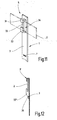
- FIGS. 7a, 7b illustrate another embodiment of the heddle 1 'according to the invention.
- the peculiarity of this heddle is that the heddle body 3 is provided on its flat side 28 with flat rod-shaped thread guide elements 24, 25 which overlap the upper edge 10 and the lower edge 11 of the thread eye 7.
- the projection of the thread guide elements 24, 25 over the edges 10, 11 is preferably so large that the warp thread does not touch the edges 10, 11.
- the projection of the thread guide elements 24, 25 over the edges 10, 11 is preferably so large that the warp thread does not reach the edges 10, 11 even if it is in a shedding position, i. when the heald has reached its upper or lower extreme position.
- FIGS. 8a and 8b show, corresponding yarn guide elements 24a, 24b, 25a, 25b can also be used on both flat sides 21, 28 of the base body 3 are attached.
- the overall width of these Fadenleit vom 17, 18 is now again greater than the thickness of the Litzen stresses 3.
- the total width is here in Figure 8b to be measured from left to right Width of the individual partial surfaces 17a, 17b, 18a, 18b plus the respective distance between the partial surfaces 17a, 17b and 18a, 18b understood.
- the thread guide elements 24, 25 may be formed as shown as separate elements or alternatively as part of a frame, each flat on the flat side 21 and / or 28 is attached. The geometry of the thread eye 7 is then determined by the frame. However, the illustrated embodiment is preferred with separate thread guide elements 24, 25 not connected to one another. The webs remaining on both sides of the thread eye 7 can vibrate or spring, without this being hindered by glued, soldered or welded elements, or by e.g. a ceramic thread guide would break. On the other hand, in the solution with a frame-shaped thread guide element, a reinforcement of the thread eye area of the strand body 3 can be achieved.
- FIGS. 9a and 9b illustrate a further embodiment based on the embodiment according to FIGS. 8a, 8b, which differs in the form of the thread guide elements 24a, 24b, 25a, 25b from the preceding embodiment.
- the thread guide elements 24a, 24b, 25a, 25b are again designed as a cylindrical pin according to FIG. They are at the Flat sides 21, 28 attached and project beyond the edges 10, 11.
- the band-shaped warp thread passes over the yarn guide elements 24a, 24b, 25a, 25b, without touching the edges 10, 11.
- the thread guiding elements 24, 25 may also be designed in the form of a cylindrical pin with end-side starting elements 29, 30 according to FIG. 10b.
- the thrust elements 29, 30 may be, for example, disk-shaped sections, the diameter D1, D2 is greater than the diameter D0 of the central cylindrical pin-shaped portion.
- the thrust elements 29, 30 may be provided with a one-sided flattening in order to facilitate attachment to one of the flat sides 21, 28 of the heddle body 3.
- Figure 11 illustrates an alternative embodiment of the end loop 5 of the heald 1, which is suitable for all the aforementioned embodiments.
- To the end eyelet 5 include projections 31, 32, which are adapted to overlap the heddle support rail 2 and thereby secure the heald 1 to the heddle support rail 2.
- the projections 31, 32 are formed in the form of angled tongues, which have been released when punching an opening 33. The tongues have then been bent out of this opening 33 and angled at their ends on each other to form the heald bar 2 cross hooks.
- This embodiment has the advantage that the heddle body 3 rests flat against the support rail 2 and thus can not suffer any torsion.
- the defined by the projections 31, 32 receiving opening 34 for the Litzentragschiene 2 has compared to the Litzentragschiene 2 a significant vertical play, but only a small other game on.
- the embodiment of the end eyelet 5 according to FIG. 11 can be modified.
- the upper projection 31 can be replaced by a correspondingly bent end 31 'of the stranded body 3, as Figure 12 illustrates schematically.
- the protrusion 32 may be replaced according to Figure 12 by an attached or welded sheet metal element 32 ', which is connected, for example, on a vertically oriented edge 35 with the heald body 3.
- the element 32 ' can be obtained by bending over an edge portion of the heddle body 3 or separately attached to it.
- a heddle 1 for flat, ribbon-like warp threads 36 has a thread eye 7, the width of which is preferably greater than its height. Such a thread eye 7 prevents deformation of the band-shaped warp thread 36, in particular a lateral collapse during shedding.
- the invention Weblitze 1 preferably Fadenleit vom 17, 18, which, based on the running direction of the warp thread 37, are longer than the thickness of the heddle body 3 of the heald 1. By this measure, the wear on the heald 1, as well as on the Warp 36 can be reduced.
Landscapes
- Engineering & Computer Science (AREA)
- Textile Engineering (AREA)
- Looms (AREA)
- Ropes Or Cables (AREA)
Abstract
Description
Die Erfindung betrifft eine Weblitze, die zur Verarbeitung von Kettfäden eingerichtet ist, die nach Art von Bändern ausgebildet sind.The invention relates to a heddle, which is adapted for processing warp threads, which are formed in the manner of ribbons.
Zur Herstellung von Geweben dienen Webmaschinen, die zumindest einen, in der Regel aber viele so genannte Webschäfte zur Fachbildung aufweisen. Jeder Webschaft wird durch einen im Wesentlichen rechteckigen Rahmen gebildet, der aus vertikal angeordneten Seitenstützen sowie einem oberen und einem unteren Holm, dem sogenannten Schaftstab, besteht. An den Schaftstäben sind Litzentragschienen gehalten, die meist durch längliche Stahlschienen mit rechteckigem Querschnitt gebildet sind. Die Stahlschienen dienen der Aufnahme von Weblitzen. Jede Weblitze weist Endösen auf, mit denen sie sich auf die obere und die untere Stahlschiene auffädeln lässt. Zwischen den Endösen erstreckt sich der Litzenkörper. Etwa mittig ist ein Fadenauge vorgesehen, durch das der Kettfaden führt. Wird der Schaftstab nach oben oder nach unten bewegt, werden alle durch die Fadenaugen der Litzen führenden Kettfäden aus der Kettfadenschar nach oben oder nach unten heraus geführt, so dass ein Webfach entsteht.For the production of fabrics are looms, which have at least one, but usually many so-called heald shanks for shedding. Each weave is formed by a substantially rectangular frame made vertically arranged side supports and an upper and a lower spar, the so-called shaft rod exists. Litzentragschienen are held on the shaft rods, which are usually formed by elongated steel rails with a rectangular cross-section. The steel rails are used to hold healds. Each heald has end loops for threading onto the top and bottom steel rails. Between the end eyelets of the heddle body extends. Approximately in the middle a thread eye is provided, through which the warp thread leads. If the shaft rod is moved upwards or downwards, all warp threads leading through the thread eyes of the strands are guided out of the warp thread bundle upwards or downwards, so that a shed is formed.
Die
Auch die
Die vorgestellten Weblitzen sind zur Verarbeitung im Wesentlichen runder Fäden geeignet. Zunehmend stellt sich jedoch die Forderung nach der Verarbeitung bandförmiger Faseranordnungen. Häufig sind beispielsweise aus Polyester-, Aramid- oder Kohlenstofffaser bestehende bandförmige Fadenanordnungen zu verarbeiten, z.B. zur Herstellung von Geweben zur Verstärkung von hochbeanspruchten Kompositstrukturen. Häufig stellt sich die Forderung, dass das bandförmige Faserbündel bei dem Webprozess seine bandförmige Struktur behält und z.B. parallel zur Gewebeebene ausgerichtet ist.The presented healds are suitable for processing substantially round threads. However, there is an increasing demand for the processing of ribbon-shaped fiber arrangements. Frequently, for example, polyester, aramid or carbon fiber band-shaped thread arrangements are to be processed, e.g. for producing fabrics for reinforcing highly stressed composite structures. Frequently the demand arises that the band-shaped fiber bundle retains its band-shaped structure in the weaving process, and e.g. aligned parallel to the tissue plane.
Davon ausgehend ist es Aufgabe der Erfindung, eine Litze zu schaffen, die zum Verweben bandartiger Kettfäden geeignet ist.On this basis, it is an object of the invention to provide a strand which is suitable for weaving ribbon-like warp threads.
Diese Aufgabe wird mit der Weblitze nach Anspruch 1 sowie mit der Weblitze nach Anspruch 2 gelöst:
- Gemäß
Anspruch 1 weist die erfindungsgemäße Weblitze einen Litzenkörper mit einem Fadenauge auf, das in Kettfadenrichtung gesehen breiter als hoch ist. Die Form des Fadenauges ist insoweit der Form des bandförmigen oder bandartigen Kettfadens oder einer entsprechenden Kettfadengruppe angenähert, die hier als Kettfaden angesehen wird. Die Breite des Fadenauges ist wenigstens einige Zehntelmillimeter größer als die Breite des bandartigen Kettfadens für den die betreffende Weblitze vorgesehen ist. Dadurch kann ein flacher bandartiger Kettfaden ungehindert durch das Fadenauge laufen, wobei er in dem Fadenauge mit geringem Vertikalspiel sicher geführt ist.
- According to
claim 1, the heddle according to the invention on a strand body with a thread eye, seen in the warp direction is wider than high. The shape of the thread eye is insofar approximated to the shape of the band-shaped or ribbon-like warp thread or a corresponding warp thread group, which is considered here as a warp thread. The width of the thread eye is at least a few tenths of a millimeter larger than the width of the ribbon-like warp thread for which the heald in question is provided. As a result, a flat ribbon-like warp thread can pass unhindered through the thread eye, being securely guided in the thread eye with little vertical clearance.
Unabhängig von dieser Maßnahme ist es gemäß Anspruch 2 vorteilhaft, das Fadenauge an seinem oberen und an seinem unteren Rand mit einer Fadenleitfläche zu versehen, die fadeneinlaufseitig und/oder fadenauslaufseitig gerundet ausgebildet ist, wobei die sich in Kettfadenrichtung erstreckende Länge dieser Fadenleitfläche größer ist als die in gleicher Richtung zu messende Dicke des Litzenkörpers. Der Litzenkörper kann relativ dünn ausgebildet sein und beispielsweise aus ausreichend festem Stahl bestehen. Die Gefahr, dass sich an dem Fadenauge dadurch scharfe Kanten bilden, die empfindliche Fäden beschädigen können, wird durch die erfindungsgemäß vorzusehende Fadenleitfläche gebannt. Die Dicke der Weblitze kann somit bis auf ein Minimum reduziert werden, was das Gewicht der Litzen und somit die Materialkosten reduziert und andererseits die mögliche erreichbare Arbeitsgeschwindigkeit erhöht.Regardless of this measure, it is advantageous according to
Vorzugsweise ist die Weblitze zumindest im Bereich des Fadenauges quer zum Kettfaden gedreht, d.h. die Flachseiten der Weblitze liegen in einer Ebene, die auch die beiden Litzentragschienen enthält oder mit diesen einen zumindest sehr spitzen Winkel nahe 0° einschließt. Dadurch wird erreicht, dass die Öffnungsrichtung des Fadenauges im Wesentlichen mit der Laufrichtung des Kettfadens übereinstimmt. Dadurch wird für die geforderte Öffnungsweite des Fadenauges die minimale Fadenaugenbreite ermöglicht.Preferably, the heald is rotated at least in the region of the thread eye transversely to the warp thread, i. the flat sides of the heald lie in a plane which also contains the two heddle rails or encloses with them an at least very acute angle near 0 °. This ensures that the opening direction of the thread eye substantially coincides with the running direction of the warp thread. As a result, the minimum thread eye width is made possible for the required opening width of the thread eye.
Für die Bildung eines Webfaches wird z.B. ein erster Webschaft nach unten in die untere Position und ein zweiter Webschaft nach oben in die obere Position bewegt. Beide Webschäfte weisen erfindungsgemäße Weblitzen auf, durch deren Fadenauge Kettfadenbänder laufen. Nach der Bewegung des ersten Webschafts in die untere Position und des zweiten Webschafts in die obere Position bildet z.B. jeweils ein Kettfaden des ersten Webschafts mit einem Kettfaden des zweiten Webschafts ein so genanntes Webfach. Der Kettfaden des ersten Webschafts verläuft durch ein Fadenauge einer Litze im ersten Webschaft im unteren Bereich, wobei der Kettfaden des zweiten Webschafts durch ein Fadenauge eine Litze des zweiten Webschafts im oberen Bereich läuft. So wird ein Webfach gebildet. Nach dem Schusseintrag in dieses Webfach verändern die beiden webschäfte ihre Position. Der erste Webschaft fährt nach oben, gleichzeitig fährt der zweite Webschaft nach unten. Mit den Webschäften verändern sich auch die Positionen der Weblitzen und somit die durch die Fadenaugen der Weblitzen laufenden Kettfäden bzw. Kettfadenbündel. Bei dieser Positionsänderung der Kettfäden streicht der Kettfaden des zweiten Webschafts an der Außenkante der benachbarten Weblitze des ersten Webschafts vorbei. Umgekehrt streicht der Kettfaden der durch das Fadenauge des ersten Webschafts läuft an der Außenkante der benachbarten Litze des zweiten webschafts vorbei.For the formation of a shed, for example, a first heald is moved down to the lower position and a second heald up to the upper position. Both heddles have healds according to the invention, through the thread eye of which warp threads run. After the movement of the first heald to the lower position and the second heald to the upper position forms, for example, in each case a warp thread of the first heald with a warp thread of the second heald a so-called shed. The warp thread of the first heald passes through a thread eye of a strand in the first heald in the lower region, wherein the warp thread of the second heald passes through a thread eye a strand of the second heald in the upper region. This is how a shed is formed. After the weft insertion into this shed the two shafts change their position. The first weaving shaft goes up, at the same time the second weaving shaft goes down. The heddles also change the positions of the heddles and thus the warp threads or warp thread bundles passing through the thread eyes of the heddles. In this change in position of the warp threads of the warp thread of the second weaving sheath sweeps past the outer edge of the adjacent heald of the first heald shaft. Conversely, the warp thread passing through the thread eye of the first heald passes the outer edge of the adjacent heald of the second web shaft.
Weil das Fadenauge einer erfindungsgemäßen Litze quer zum Kettfaden gedreht ist, kann der Bereich zwischen Außenkante der Litze und Fadenauge sehr klein ausgebildet werden. Dies bietet einem Kettfadenband einer benachbarten Litze eines benachbarten Webschafts beim Positionswechsel ausreichend Raum, um ungehindert an der Kante der Weblitze des benachbarten Webschafts vorbei zu streichen. Somit wird die Gefahr der Verletzung von Kettfäden beim Positionswechsel stark reduziert. Zusätzlich ist die Bildung von engmaschigen Geweben möglich. Zum gleichen Zweck, der Bildung von engmaschigen Geweben, kann eine geringe Schrägstellung der Litzenkörper im Bereich des Fadenauges dienen, wodurch die Öffnungsrichtung des Fadenauges in einem spitzen Winkel von wenigen Grad gegen die in Anspruch 3 genannte Ebene geneigt ist.Because the thread eye of a strand according to the invention is rotated transversely to the warp thread, the area between the outer edge of the strand and the thread eye can be made very small. This provides a warp thread of an adjacent strand of an adjacent heald shaft when changing position enough space to pass freely on the edge of the heald of the adjacent heald shaft over. Thus, the risk of injury to warp threads when changing position is greatly reduced. In addition, the formation of close-meshed tissues is possible. For the same purpose, the formation of close-meshed fabrics, may serve a slight inclination of the strand body in the region of the thread eye, whereby the opening direction the thread eye is inclined at an acute angle of a few degrees against the plane mentioned in
Vorzugsweise besteht der Litzenkörper aus einem bandförmigen Material, z.B. einem Stahlband. Zumindest an seinem Fadenauge kann er quer zu dem Kettfaden orientiert sein. Die Verwindung zwischen dem Fadenauge und den Endösen beträgt vorzugsweise 90°. Damit werden die oben beschriebenen Verhältnisse und Vorteile erreicht.Preferably, the heddle body is made of a band-shaped material, e.g. a steel band. At least on his thread eye he can be oriented transversely to the warp. The twist between the thread eye and the end eyelets is preferably 90 °. Thus, the above-described conditions and advantages are achieved.
Die Endöse kann durch ein gesondertes, mit dem Litzenkörper verbundenes Element gebildet sein. Vorzugsweise ist sie jedoch einstückiger Bestandteil des Litzenkörpers, d.h. sie besteht aus demselben Material wie dieser und geht naht- und übergangslos in diesen über. Die Weblitze kann dadurch als einfacher Stanzkörper hergestellt werden. Die Endöse kann jede bekannte Form wie die so genannte O-Form, C-Form oder J-Form oder auch jede zukünftig entwickelte Form haben.The Endöse can be formed by a separate, connected to the heald body element. Preferably, however, it is an integral part of the strand body, i. It is made of the same material as this one and goes seamlessly and seamlessly into it. The heald can thereby be produced as a simple punched body. The end eyelet may have any known shape such as the so-called O-shape, C-shape or J-shape or any future developed form.
Es ist auch möglich, die Weblitze ohne Verwindung aus einem Flachmaterial herzustellen, wobei die Endösen durch Vorsprünge gebildet sind, die an dem Litzenkörper angebracht sind und über dessen Flachseite vorstehen. Die vorsprünge können beispielsweise durch Zungen gebildet sein, die aus dem Litzenkörper freigeschnitten und seitlich ausgebogen sind. Die Vorsprünge können außerdem durch an die Flachseite des Litzenkörpers nachträglich angebrachte Elemente gebildet sein. Solche Elemente können beispielsweise durch Laserschweißen angebrachte oder auch angenietete Blechlaschen sein, wobei die Schweißnaht längs oder quer zu der Längsrichtung des Litzenkörpers geführt sein kann. Die Version mit längs orientierter Schweißnaht führt zu einer besonders hohen Stabilität der so gebildeten Endöse.It is also possible to make the heald without twisting from a flat material, wherein the end eyelets are formed by projections which are attached to the heald body and protrude over the flat side. The projections can be formed for example by tongues, which are cut free from the heald body and bent out laterally. The projections may also be formed by subsequently attached to the flat side of the strand body elements. Such elements may be, for example, by laser welding or riveted metal tabs, wherein the weld can be made longitudinally or transversely to the longitudinal direction of the strand body. The version with longitudinally oriented weld leads to a particularly high stability of the end eyelet thus formed.
Besonderes Augenmerk richtet die Erfindung bei einer bevorzugten Ausführungsform auf die Ausbildung der Fadenleitflächen, die beispielsweise durch Laschen gebildet sein können, die aus dem Fadenauge herausgebogen sind. Bei einer bevorzugten Ausführungsform sind die freigestellten Laschen um wenigstens 110° aus dem Fadenauge heraus gebogen. Es werden dadurch großzügig dimensionierte Fadenleitflächen erhalten, mit denen auch spröde bruchempfindliche Fäden gewebt werden können.Particular attention is directed to the invention in a preferred embodiment on the formation of Fadenleitflächen, which may be formed for example by tabs that are bent out of the thread eye. In a preferred embodiment, the released tabs are bent out of the thread eye by at least 110 °. This results in generously dimensioned yarn guide surfaces, which can be used to weave brittle, break-sensitive threads.
Insbesondere zur Verarbeitung stark haftender oder abrasiver Fäden ist es vorteilhaft, die Fadenleitflächen an gesonderten Elementen auszubilden, die mit dem Litzenkörper verbunden sind. Sie bilden somit den oberen und/oder den unteren Rand des Fadenauges. Die gesonderten Elemente können aus gehärtetem Stahl, Hartmetall, Kunststoff oder Keramik bestehen. Die Elemente können mit dem Litzenkörper durch Kleben, Löten oder Schweißen verbunden werden. Die Verwendung von Hartmetall oder Keramik gestattet das Verweben besonders aggressiver Bänder, wie beispielsweise Aramidfasern. Die zusätzlichen Elemente können außerdem mit Abschnitten versehen sein, die wenigstens einen Teil der seitlichen Flanken des Fadenauges schützen. Dies wird beispielsweise erreicht, indem die Elemente die Form eines endseitig mit Platten oder Scheiben versehenen Stifts aufweisen. Des Weiteren ist es vorteilhaft, die Weblitze im Bereich des Fadenauges mit einer Hartstoffauflage, beispielsweise Titannitrid oder einer anderweitigen Hartstoffverbindung, zu versehen. Diese Auflage kann, wenn zur Ausbildung der Fadenleitfläche Hartmetallelemente verwendet werden, sich auf die Hartmetallelemente beschränken.In particular, for processing strongly adhering or abrasive threads, it is advantageous to form the Fadenleitflächen on separate elements which are connected to the strand body. They thus form the upper and / or the lower edge of the thread eye. The separate elements may be made of hardened steel, carbide, plastic or ceramic. The elements can be connected to the strand body by gluing, soldering or welding. The use of cemented carbide or ceramic allows interweaving particularly aggressive tapes, such as aramid fibers. The additional elements may also be provided with portions which protect at least a portion of the lateral flanks of the thread eye. This is achieved, for example, by having the elements in the form of a pin or disk end pin. Furthermore, it is advantageous to provide the heald in the region of the thread eye with a hard material support, for example titanium nitride or another hard material compound. This edition can, if to form the yarn guide carbide elements be limited to the carbide elements.
Bei einer sehr kostengünstigen Ausführungsform der erfindungsgemäßen Litze überragen die Elemente den oberen und den unteren Rand des Fadenauges deutlich. Die Elemente sind in Form kleinerer, an den Flachseiten des Litzenkörpers angeordneter Plättchen ausgebildet, deren Kanten gut gerundet sind. Diese Plättchen werden an der vorderen und rückseitigen Flachseite des Litzenkörpers befestigt und legen gemäß ihrer Positionierung die Höhe des Fadenauges in Längsrichtung der Litze fest. Mit dieser Maßnahme können an einheitlich ausgestanzten Litzenkörpern Fadenaugen unterschiedlicher Höhe realisiert werden, so dass die betreffenden Litzen für unterschiedliche bandförmige Kettfäden eingerichtet sein können.In a very cost-effective embodiment of the strand according to the invention, the elements clearly project beyond the upper and lower edges of the thread eye. The elements are in the form of smaller, arranged on the flat sides of the strand body platelets whose edges are well rounded. These plates are attached to the front and back flat side of the strand body and lay according to their positioning, the height of the thread eye in the longitudinal direction of the strand. With this measure, thread eyes of different height can be realized on uniformly punched strand bodies, so that the respective strands can be set up for different band-shaped warp threads.
Weitere Einzelheiten vorteilhafter Ausführungsformen der Erfindung sind Gegenstand der Zeichnung, der Beschreibung oder von Ansprüchen. In der Zeichnung sind Ausführungsbeispiele der Erfindung veranschaulicht. Es zeigen:
Figur 1 einen Webschaft mit einer Weblitze in ausschnittsweiser, schematisierter Perspektivdarstellung,Figur 2 dieWeblitze nach Figur 1 in einer ausschnittsweisen, perspektivischen Ansicht ihres Fadenauges,- Figur 3a und 3b eine abgewandelte Ausführungsform des Fadenauges einer Weblitze in Draufsicht nach dem Ausstanzen der Weblitze (Figur 3a) und im Vertikalschnitt nach Fertigstellung des Fadenauges (Figur 3b),
- Figur 4a und 4b eine abgewandelte Ausführungsform eines Fadenauges mit Elementen zur Festlegung von Fadenleitflächen in Draufsicht (Figur 4a) und im Vertikalschnitt (Figur 4b),
- Figur 5a und 5b eine weitere Ausführungsform eines Fadenauges mit Elementen zur Ausbildung von Fadenleitflächen in Draufsicht (Figur 5a) und im Vertikalschnitt (Figur 5b),
- Figur 6a und 6b ein Fadenauge mit formschlüssig unterstützten Elementen zur Festlegung von Fadenleitflächen in Draufsicht (Figur 6a) und im Vertikalschnitt (Figur 6b),
- Figur 7a und 7b eine abgewandelte Ausführungsform des Fadenauges einer Weblitze mit in Form von Plättchen ausgebildeten Elementen zur Ausbildung von Fadenleitflächen in Draufsicht (Figur 7a) und im Vertikalschnitt (Figur 7b),
- Figur 8a und 8b eine Ausführungsform einer Weblitze mit verbreiterter Fadenauflagefläche in Draufsicht (Figur 8a) und im Vertikalschnitt (Figur 8b),
- Figur 9a und 9b eine abgewandelte Ausführungsform der Weblitze mit runden Fadenleitelementen an ihrem Fadenauge in Draufsicht (Figur 9a) und im Vertikalschnitt (9b),
- Figur 10a ein Fadenleitelement für eine weblitze gemäß Figur 4a, 4b oder alternativ Figur 9a, 9b,
- Figur 10b ein Fadenleitelement für die Weblitze nach Figur 4a, 4b oder alternativ Figur 9a, 9b,
Figur 11 dieWeblitze nach Figur 1 mit einer abgewandelten Ausführungsform einer Endöse ohne Verdrehung des Litzenkörpers in perspektivischer Darstellung undFigur 12 eine abgewandelte Ausführungsform der Endöse in schematischer Darstellung.
- FIG. 1 shows a heddle with a heddle in a fragmentary, schematic perspective view;
- FIG. 2 shows the heddle according to FIG. 1 in a fragmentary, perspective view of its thread eye;
- 3a and 3b show a modified embodiment of the thread eye of a heald in plan view after the punching of the heddle (FIG. 3a) and in vertical section after completion of the thread eye (FIG. 3b), FIG.
- 4a and 4b show a modified embodiment of a thread eye with elements for fixing thread guide surfaces in plan view (FIG. 4a) and in a vertical section (FIG. 4b), FIG.
- 5a and 5b show a further embodiment of a thread eye with elements for the formation of yarn guide surfaces in plan view (FIG. 5a) and in a vertical section (FIG. 5b), FIG.
- 6a and 6b, a thread eye with positively supported elements for fixing Fadenleitflächen in plan view (Figure 6a) and in vertical section (Figure 6b),
- 7a and 7b show a modified embodiment of the thread eye of a heddle with elements formed in the form of platelets for the formation of thread guide surfaces in plan view (FIG. 7a) and in a vertical section (FIG. 7b), FIG.
- 8a and 8b show an embodiment of a heald having a widened thread support surface in plan view (FIG. 8a) and in a vertical section (FIG. 8b), FIG.
- FIGS. 9a and 9b show a modified embodiment of the heddle with round thread guide elements on its thread eye in plan view (FIG. 9a) and in vertical section (9b),
- FIG. 10a shows a thread guiding element for a woven strand according to FIG. 4a, 4b or alternatively FIG. 9a, 9b, FIG.
- 10b shows a thread guide element for the heddle according to FIG. 4a, 4b or alternatively FIG. 9a, 9b, FIG.
- Figure 11 shows the heddle according to Figure 1 with a modified embodiment of an end eye without rotation of the heddle body in a perspective view and
- Figure 12 shows a modified embodiment of the end eye in a schematic representation.
In Figur 1 ist eine Weblitze 1 für flache, bandförmige, nicht weiter veranschaulichte Kettfäden dargestellt. Die Weblitze 1 gehört zu einer Gruppe gleich oder ähnlich ausgebildeter Weblitzen, die auf einem Webschaft gehalten sind, wie er zur Fachbildung an einer webmaschine verwendet wird. Die Weblitze 1 ist auf zwei Litzentragschienen 2, 2' gelagert, die im Abstand parallel zueinander an dem oberen und dem unteren Schaftstab eines Webschafts gehalten sind. Die Weblitze 1 weist einen aus Stahlblechstreifen bestehenden Grundkörper 3 auf, dessen Längsrichtung 4 in Figur 1 vertikal und dabei rechtwinklig zu den Litzentragschienen 2, 2' orientiert ist. Er weist an seinen Enden Endösen 5, 6 auf, die im einfachsten Fall durch in den Grundkörper 3 eingestanzte Öffnungen gebildet werden können, deren Form und Größe mit einer entsprechenden Spielzugabe dem Querschnitt der Litzentragschienen 2, 2' entspricht. In einem zwischen den Endösen 5, 6 liegenden Bereich ist der Grundkörper 3 mit einem Fadenauge 7 versehen, das zur Aufnahme eines Kettfadens dient. Das Fadenauge 7 weist dabei, wie insbesondere Figur 2 erkennen lässt, einen im Wesentlichen rechteckigen Querschnitt auf, wobei seine seitlichen Kanten 8, 9, die sich in Längsrichtung 4 erstrecken, kürzer sind als seine obere und seine untere Kante 10, 11, die quer zu der Längsrichtung 4 stehen.FIG. 1 shows a
Wie Figur 1 erkennen lässt, ist das Fadenauge 7 von einem flachen, im Wesentlichen ebenen Bereich 12 umgeben, der wenigstens ungefähr in oder parallel einer Ebene liegt, die von den Litzentragschienen 2, 2' festgelegt ist. Dazu ist die Weblitze 1 zwischen dem Bereich 12 und der jeweiligen Endöse 6, 7 jeweils an Stellen 13, 14 um etwa 90° um die Längsrichtung 4 verwunden.As can be seen from FIG. 1, the
Wie die Figuren 1 und 2 erkennen lassen, ist der Litzenkörper aus einem relativ dünnen Flachmaterial aus Metall, beispielsweise Stahl als reines Stanzbiegeteil einstückig ausgebildet. Die Endösen 5, 6 sind Bestandteil des Litzenkörpers 3. Die Breite des Litzenkörpers 3 ist wenigstens an dem Bereich 12, vorzugsweise aber insgesamt größer als die in Figur 2 veranschaulichte Breite B des Fadenauges 7. Zu beiden Seiten des Fadenauges 7 verbleiben Stege 15, 16, deren Breite vorzugsweise etwas größer ist als die Dicke des Flachmaterials aus dem die Weblitze 1 ausgebildet ist. Die in Längsrichtung 4 zu messende Höhe H des Fadenauges 7 ist deutlich geringer als seine Breite B. Das Fadenauge 7 kann allerdings abweichend von der in Figur 2 veranschaulichten Rechteckform auch oval oder anderweitig geformt sein, wobei aber jeweils seine Breite B größer als seine Höhe H ist.As can be seen from FIGS. 1 and 2, the heddle body is formed integrally from a relatively thin flat material made of metal, for example steel as a pure stamped and bent part. The width of the
Die obere und die untere Kante 10, 11 werden vorzugsweise durch Fadenleitflächen 17, 18 gebildet, die, wie in Figur 2 dargestellt, unmittelbar an die Flachseiten des Bereichs 12 anschließen können. Die Übergänge können jedoch gerundet sein, um empfindliche Kettfäden 36 zu schonen. Die Kettfäden 36 können jeweils durch einzelne Fäden bzw. Streifen (z.B. Kunststoffbänder) oder jeweils aus mehreren miteinander verbundenen oder unverbundenen Fäden, einer Fadenschar oder einem Fadenband 36 gebildet sein.The upper and
Die insoweit beschriebene Weblitze 1 arbeitet wie folgt:
- Für den Betrieb einer Webmaschine, zur Bildung eines Webfachs, werden mehrere Weblitzen 1 gemäß der Bauart nach Figur 1 auf die
Litzentragschienen 2, 2' von mindestens zwei webschäften aufgereiht.Die Weblitzen 1 sind im einfachsten Fall untereinander vollkommen identisch ausgebildet. Sie sind pro Webschaft in einem Abstand, der im Wesentlichen der Kettfadenbreite 36 entspricht, gehalten.Durch die Fadenaugen 7 laufen diejenigen bandförmigen Kettfäden 36, die der Fachbildung zu unterwerfen sind. Zur Fachbildung werden die beiden Webschäfte, mitvon den Litzentragschienen 2, 2'gehaltenen Weblitzen 1, in Längsrichtung 4 auf und ab bewegt. Dabei werden die durch dieFadenaugen 7 laufenden bandförmigen Kettfäden 36 unverformt nach oben oder nach unten ausgelenkt und somit ein Webfach gebildet, welches dem Schusseintrag eines Schussfadens zur Verfügung steht.
- For the operation of a weaving machine, to form a shed, a plurality of
healds 1 according to the design of Figure 1 are strung on theLitzentragschienen 2, 2 'of at least two webschäften. Thehealds 1 are the simplest Case formed completely identical to each other. They are held per heald at a distance which essentially corresponds to thewarp width 36. Through thethread eyes 7 run those band-shapedwarp threads 36, which are subject to the shedding. For shedding, the two healds are moved up and down in the longitudinal direction 4 withheddles 1 held by the heddle support rails 2, 2 '. The current through thethread eyes 7 band-shapedwarp threads 36 are deflected undeformed up or down, thus forming a shed, which is the weft insertion of a weft available.
Bei einer abgewandelten Ausführungsform sind die Bereiche 12 der Weblitzen 1 nicht um genau 90° gegen die Endösen 5, 6 gedreht. Die Weblitzen 1 des ersten und zweiten Webschafts können sich dadurch etwas überlappen, wodurch dichtere Gewebe hergestellt werden können. Auch bei dieser Ausführungsform ist die aus Sicht des Kettfadens 36 vorhandene lichte Weite zumindest geringfügig größer als die Breite des flachen Kettfadens 36.In a modified embodiment, the
Es ist weiter möglich, die Weblitze 1 geringfügig asymmetrisch zu gestalten, entweder indem die Öffnungen der Endösen 5, 6 außermittig in den Litzenkörper 3 eingestanzt werden oder indem die verwundenen Bereiche bzw. die Drehbereiche 13, 14 etwas asymmetrisch gebogen werden.It is further possible to make the
Die Figuren 3a und 3b veranschaulichen eine abgewandelte Ausführungsform der Weblitze 1, für die die vorstehende Erläuterung mit Ausnahme nachfolgenden Abwandlungen und Ergänzungen entsprechend gilt. Das Fadenauge 7 ist wiederum im Wesentlichen rechteckig ausgebildet. Jedoch wird es zunächst, wie in Figur 3a veranschaulicht, H-förmig ausgestanzt, so dass ein oberer und ein unterer Lappen 19, 20 freigestellt werden, die sich aufeinander zu erstrecken. Die Lappen 19, 20 werden dann, wie Figur 3b veranschaulicht, voneinander weg gebogen. Sie können dabei, wie dargestellt, zur gleichen Seite oder auch in entgegen gesetzten Richtungen aus dem Fadenauge 7 heraus gebogen werden und formen ein keil- oder trichterförmiges Fadenauge. Vorzugsweise werden sie dabei um einen Winkel gebogen, der deutlich größer als 90° ist. Die bevorzugten Ausführungsbeispiele nutzen Winkel α zwischen 110° und 150°. Die Lappen 19, 20 können dabei in Fadenlaufrichtung oder gegen die Laufrichtung der Kettfäden 36 orientiert sein. In jedem Fall entstehen Fadenleitflächen 17, 18, die, wie aus Figur 3b ersichtlich, an einer Flachseite 21 des Bereichs 12 beginnen und sich jeweils bis zu dem freien Ende 22, 23 jedes Lappens 19, 20 erstrecken. Die entsprechend zu messende Länge ist somit größer als die Dicke des Litzenkörpers 3. Diese Ausführungsform eignet sich insbesondere für bandförmige Kettfäden 36 aus empfindlichem, aber wenig abrasivem Material.Figures 3a and 3b illustrate a modified embodiment of the
Es wird darauf hingewiesen, dass die Weblitze 1' wie auch alle nachfolgend beschriebenen Weblitzen 1' ein Fadenauge 7 mit einer Höhe H haben, die geringer ist als die Breite B. Jedoch können die Weblitzen 1' dieser Ausführungsformen ausnahmslos auch mit Fadenaugen 7 versehen sein, deren Höhe H größer ist als deren Breite B.It should be noted that the heald 1 'as well as all healds described below 1' have a
In den Figuren 4a, 4b ist eine weitere Ausführungsform der Weblitze 1' veranschaulicht. Die Besonderheit dieser Ausführungsform besteht in Fadenleitelementen 24, 25, die das Fadenauge 7 oben und unten beranden und somit einen oberen und einen unteren Rand bilden. Die Fadenleitelemente 24, 25 sind z.B. durch zylindrische Stifte gebildet, die in entsprechenden Auskehlungen 26, 27 liegen, die an den Kanten 10, 11 ausgebildet sind. Diese Auskehlungen können rinnenförmig gebildet sein. Die Fadenelemente 24, 25 weisen vorzugsweise einen Durchmesser auf, der größer ist als die Dicke des Litzenkörpers 3. Dadurch erhalten die Fadenleitflächen 17, 18, die an den Fadenleitelementen 24, 25 ausgebildet sind, eine Länge, die größer ist als die Dicke des Litzenkörpers 3.FIGS. 4a, 4b illustrate another embodiment of the heald 1 '. The peculiarity of this embodiment is in
Die Fadenleitelemente 24, 25 sind untereinander vorzugsweise gleich ausgebildet. Sie können beispielsweise gemäß Figur 10a ausgebildet sein und aus einem geeigneten Material, wie beispielsweise gehärtetem Stahl, Hartmetall, Keramik oder einem anderen verschleißfesten Stoff bestehen. Sie können mit dem Litzenkörper 3 verlötet, verschweißt oder verklebt sein. Außerdem kann das Fadenleitelement 24, 25 aus einem Kunststoff bestehen. Die Wahl des Materials des Fadenleitelements 24, 25 kann sich an dem von dem Fadenauge 7 zu leitenden Kettfaden orientieren.The
In Figur 5a, 5b ist eine abgewandelte Ausführungsform der Weblitze 1' veranschaulicht. Die Fadenleitelemente 24, 25 weisen hier einen teilzylindrischen, vorzugsweise halbrunden Querschnitt auf. Dies vereinfacht die Herstellung hinsichtlich der Lagerung des Fadenleitelements 24, 25 und der Befestigung desselben an dem Litzenkörper 3. Ansonsten gilt die vorige Beschreibung des Ausführungsbeispiels gemäß Figur 4a, 4b entsprechend für das Ausführungsbeispiel gemäß Figur 5a, 5b.In Figure 5a, 5b, a modified embodiment of the heald 1 'is illustrated. The
Figur 6a, 6b veranschaulicht eine weitere abgewandelte Ausführungsform der Weblitze 1'. Bei dieser Ausführungsform sind Fadenleitelemente 24, 25 vorgesehen, die von einer zylindrischen Grundform ausgehen und zur Aufnahme des Litzenkörpers 3 an ihren von dem Fadenauge 7 weg weisenden Seiten jeweils eine entsprechende Nut aufweisen. Die Fadenleitelemente 24, 25 können auf diese Weise einfach und sicher an dem Litzenkörper 3 befestigt werden. Bevorzugt wird eine stoffschlüssige Verbindung durch Kleben, Löten oder Schweißen. Ansonsten gelten die vorigen Ausführungen entsprechend.Figure 6a, 6b illustrates another modified embodiment of the heald 1 '. In this embodiment,
In den Figuren 7a, 7b ist eine weitere Ausführungsform der erfindungsgemäßen Weblitze 1' veranschaulicht. Die Besonderheit dieser Weblitze besteht darin, dass der Litzenkörper 3 an seiner Flachseite 28 mit flachstabförmigen Fadenleitelementen 24, 25 versehen ist, die die obere Kante 10 und die untere Kante 11 des Fadenauges 7 überlappen. Die Fadenleitflächen 17, 18, die durch gerundete Kanten der Fadenleitelemente 24, 25 gebildet werden, begrenzen dabei die lichte Höhe H des Fadenauges 7, wobei diese lichte Höhe H deutlich geringer ist als der in gleicher Richtung gemessene Abstand zwischen den Kanten 10, 11. Der Überstand der Fadenleitelemente 24, 25 über die Kanten 10, 11 ist vorzugsweise so groß, dass der Kettfaden die Kanten 10, 11 nicht berührt. Der Überstand der Fadenleitelemente 24, 25 über die Kanten 10, 11 ist dabei vorzugsweise so groß, dass der Kettfaden die Kanten 10, 11 auch dann nicht erreicht, wenn er in Fachbildestellung steht, d.h. wenn der Webschaft seine obere oder seine untere Extremposition erreicht hat.FIGS. 7a, 7b illustrate another embodiment of the heddle 1 'according to the invention. The peculiarity of this heddle is that the
Wie die Figuren 8a und 8b zeigen, können entsprechende Fadenleitelemente 24a, 24b, 25a, 25b auch an beiden Flachseiten 21, 28 des Grundkörpers 3 befestigt werden. Dadurch entstehen jeweils in Teilflächen 17a, 17b, 18a, 18b unterteilte Fadenleitflächen 17, 18. Die Gesamtbreite dieser Fadenleitflächen 17, 18 wird nun wiederum größer als die Dicke des Litzenkörpers 3. Als Gesamtbreite wird hier die in Figur 8b von links nach rechts zu messende Breite der einzelnen Teilflächen 17a, 17b, 18a, 18b zuzüglich des jeweiligen Abstands zwischen den Teilflächen 17a, 17b bzw. 18a, 18b verstanden.As FIGS. 8a and 8b show, corresponding
Sowohl bei dem Ausführungsbeispiel nach Figur 7a, 7b als auch bei dem Ausführungsbeispiel nach Figur 8a, 8b können die Fadenleitelemente 24, 25 wie dargestellt als gesonderte Elemente oder alternativ auch als Teil eines Rahmens ausgebildet sein, der jeweils flach auf die Flachseite 21 und/oder 28 aufgesetzt wird. Die Geometrie des Fadenauges 7 wird dann von dem Rahmen festgelegt. Bevorzugt wird jedoch die veranschaulichte Ausführungsform mit gesonderten, untereinander nicht verbundenen Fadenleitelementen 24, 25. Die zu beiden Seiten des Fadenauges 7 verbleibenden Stege können schwingen oder federn, ohne dass dies durch aufgeklebte, gelötete oder geschweißte Elemente behindert würde oder dass dadurch z.B. ein keramisches Fadenleitelement brechen würde. Andererseits kann bei der Lösung mit rahmenförmigem Fadenleitelement eine Verstärkung des Fadenaugenbereichs des Litzenkörpers 3 erreicht werden.Both in the embodiment of Figure 7a, 7b and in the embodiment of Figure 8a, 8b, the
Figur 9a und 9b veranschaulicht eine auf der Ausführungsform nach Figur 8a, 8b beruhende weitere Ausführungsform, die sich in der Form der Fadenleitelemente 24a, 24b, 25a, 25b von der vorstehenden Ausführungsform unterscheidet. Die Fadenleitelemente 24a, 24b, 25a, 25b sind wiederum gemäß Figur 10a als Zylinderstift ausgebildet. Sie sind an den Flachseiten 21, 28 angebracht und überragen die Kanten 10, 11. Der bandförmige Kettfaden läuft über die Fadenleitelemente 24a, 24b, 25a, 25b, ohne die Kanten 10, 11 zu berühren.FIGS. 9a and 9b illustrate a further embodiment based on the embodiment according to FIGS. 8a, 8b, which differs in the form of the
Bei den vorgenannten Ausführungsformen können die Fadenleitelemente 24, 25 auch gemäß Figur 10b in Form eines Zylinderstifts mit endseitigen Anlaufelementen 29, 30 ausgebildet sein. Die Anlaufelemente 29, 30 können beispielsweise scheibenförmige Abschnitte sein, deren Durchmesser D1, D2 größer ist als der Durchmesser D0 des mittleren zylinderstiftförmigen Abschnitts. Die Anlaufelemente 29, 30 können mit einer einseitigen Abflachung versehen sein, um das Anbringen an einer der Flachseiten 21, 28 des Litzenkörpers 3 zu erleichtern.In the aforementioned embodiments, the
Figur 11 veranschaulicht eine alternative Ausführungsform der Endöse 5 der Weblitze 1, die sich für alle vorgenannten Ausführungsformen eignet. Zu der Endöse 5 gehören Vorsprünge 31, 32, die dazu eingerichtet sind, die Litzentragschiene 2 zu übergreifen und dadurch die Weblitze 1 an der Litzentragschiene 2 zu sichern. Im vorliegenden Ausführungsbeispiel sind die Vorsprünge 31, 32 in Form abgewinkelter Zungen ausgebildet, die beim Ausstanzen einer Öffnung 33 freigestellt worden sind. Die Zungen sind dann aus dieser Öffnung 33 heraus gebogen und an ihren Enden auf einander zu abgewinkelt worden, um die Litzentragschiene 2 übergreifende Haken zu bilden. Diese Ausführungsform hat den Vorteil, dass der Litzenkörper 3 flach an der Tragschiene 2 anliegt und somit keine Verdrehung erleiden kann. Die von den Vorsprüngen 31, 32 definierte Aufnahmeöffnung 34 für die Litzentragschiene 2 weist gegenüber der Litzentragschiene 2 ein erhebliches Vertikalspiel, jedoch nur ein geringes sonstiges Spiel auf.Figure 11 illustrates an alternative embodiment of the
Die Ausführungsform der Endöse 5 gemäß Figur 11 kann abgewandelt werden. Beispielsweise kann der obere Vorsprung 31 durch ein entsprechend umgebogenes Ende 31' des Litzenkörpers 3 ersetzt werden, wie Figur 12 schematisch veranschaulicht. Auch kann der Vorsprung 32 gemäß Figur 12 durch ein angesetztes oder angeschweißtes Blechelement 32' ersetzt sein, das beispielsweise an einer vertikal orientierten Kante 35 mit dem Litzenkörper 3 verbunden ist. Das Element 32' kann durch Umbiegen eines Randabschnitts des Litzenkörpers 3 erhalten oder gesondert an diesen angesetzt werden.The embodiment of the
Eine Weblitze 1 für flache, bandartige Kettfäden 36 weist ein Fadenauge 7 auf, dessen Breite vorzugsweise größer als seine Höhe ist. Ein solches Fadenauge 7 verhindert eine Verformung des bandförmigen Kettfadens 36, insbesondere ein seitliches Zusammenschieben während der Fachbildung. Außerdem weist die erfindungsgemäße weblitze 1 vorzugsweise Fadenleitflächen 17, 18 auf, die, bezogen auf die Laufrichtung des Kettfadens 37, länger sind als die Dicke des Litzenkörpers 3 der Weblitze 1. Durch diese Maßnahme kann der Verschleiß an der Weblitze 1, wie auch an dem Kettfaden 36 reduziert werden.A
- 11
- Weblitzeheald
- 2, 2'2, 2 '
- Litzentragschieneshaft stave
- 33
- Grundkörperbody
- 44
- Längsrichtunglongitudinal direction
- 5, 65, 6
- Endösenend loops
- 77
- Fadenaugethread eye
- 8, 9, 10, 118, 9, 10, 11
- Kantenedge
- 1212
- BereichArea
- 13, 1413, 14
- Stellen, DrehstellenBodies, turning points
- 15, 1615, 16
- StegeStege
- 17, 1817, 18
- Fadenleitflächenthread guiding surfaces
- 17a, 17b, 18b, 18b17a, 17b, 18b, 18b
- Teilflächensubareas
- 19, 2019, 20
- Lappencloth
- 2121
- Flachseiteflat side
- 22, 2322, 23
- EndeThe End
- 24, 25, 24a, 24b, 25a, 25b24, 25, 24a, 24b, 25a, 25b
- Fadenleitelementethread guiding elements
- 26, 2726, 27
- Auskehlungengrooves
- 2828
- Flachseiteflat side
- 29, 3029, 30
- Endseitige AnlaufelementeEnd stop elements
- 31, 3231, 32
- Vorsprüngeprojections
- 31'31 '
- umgebogenes Endebent end
- 32'32 '
- Blechelementsheet metal element
- 3333
- Öffnungopening
- 3434
- Aufnahmeöffnungreceiving opening
- 3535
- Kanteedge
- BB
- Breitewidth
- HH
- Höheheight
- D0, D1, D2D0, D1, D2
- Durchmesserdiameter
Claims (11)
mit einem sich entlang einer Längsrichtung (4) erstreckenden Litzenkörper (3), der an wenigstens einem Ende mit einer Endöse (5, 6) zur Lagerung an einer Litzentragschiene (2, 2') versehen ist,
mit einem Fadenauge (7), das an dem Litzenkörper (3) vorgesehen ist und dessen quer zu der Längsrichtung (4) und parallel zu der Litzentragschiene (2, 2') zu messende Breite (B) größer ist als seine in Längsrichtung (4) zu messende Höhe (H).Heald (1) for ribbon-like warp threads (36),
with a heddle body (3) extending along a longitudinal direction (4), which is provided at least at one end with an end eye (5, 6) for mounting on a heddle support rail (2, 2 '),
with a thread eye (7) which is provided on the heddle body (3) and whose width (B) to be measured transversely to the longitudinal direction (4) and parallel to the heddle support rail (2, 2 ') is greater than its longitudinal direction (4) ) height to be measured (H).
mit einem sich entlang einer Längsrichtung (4) erstreckenden Litzenkörper (3), der an wenigstens einem Ende mit einer Endöse (5, 6) zur Lagerung an einer Litzentragschiene (2, 2') versehen ist,
mit einem Fadenauge (7), das an dem Litzenkörper (3) vorgesehen ist und das eine obere Kante (10) und eine untere Kante (11) aufweist, die voneinander in Längsrichtung (4) beabstandet sind,
wobei die obere Kante (10) und die untere Kante (11) eine Fadenleitfläche (17, 18) bilden, die fadeneinlaufseitig und/oder fadenauslaufseitig gerundet ausgebildet ist und deren sich in Kettfadenrichtung (36) erstreckende Länge größer ist als die in gleicher Richtung zu messende Dicke des Litzenkörpers (3) an dem Fadenauge (7).Heald (1) for ribbon-like warp threads (36),
with a heddle body (3) extending along a longitudinal direction (4), which is provided at least at one end with an end eye (5, 6) for mounting on a heddle support rail (2, 2 '),
a thread eye (7) provided on the heddle body (3) and having an upper edge (10) and a lower edge (11) spaced from one another in the longitudinal direction (4),
wherein the upper edge (10) and the lower edge (11) form a thread guide surface (17, 18), which is formed on the thread inlet side and / or thread outlet side rounded and extending in the warp direction (36) Length is greater than the thickness of the heddle body (3) to be measured in the same direction on the thread eye (7).
Priority Applications (6)
| Application Number | Priority Date | Filing Date | Title |
|---|---|---|---|
| EP20050026813 EP1795635B1 (en) | 2005-12-08 | 2005-12-08 | Heald for warp yarns having a band shape |
| DE200550005422 DE502005005422D1 (en) | 2005-12-08 | 2005-12-08 | Heald for band-shaped warp threads |
| JP2006328234A JP4617288B2 (en) | 2005-12-08 | 2006-12-05 | Heddle for band warp |
| TW95145547A TWI332534B (en) | 2005-12-08 | 2006-12-07 | Heddle for band-shaped warp threads |
| CN2006101642468A CN1978723B (en) | 2005-12-08 | 2006-12-07 | Heddle for band-shaped warp threads |
| US11/635,612 US7581566B2 (en) | 2005-12-08 | 2006-12-08 | Heddle for band-shaped warp threads |
Applications Claiming Priority (1)
| Application Number | Priority Date | Filing Date | Title |
|---|---|---|---|
| EP20050026813 EP1795635B1 (en) | 2005-12-08 | 2005-12-08 | Heald for warp yarns having a band shape |
Publications (2)
| Publication Number | Publication Date |
|---|---|
| EP1795635A1 true EP1795635A1 (en) | 2007-06-13 |
| EP1795635B1 EP1795635B1 (en) | 2008-09-17 |
Family
ID=36282661
Family Applications (1)
| Application Number | Title | Priority Date | Filing Date |
|---|---|---|---|
| EP20050026813 Expired - Fee Related EP1795635B1 (en) | 2005-12-08 | 2005-12-08 | Heald for warp yarns having a band shape |
Country Status (5)
| Country | Link |
|---|---|
| EP (1) | EP1795635B1 (en) |
| JP (1) | JP4617288B2 (en) |
| CN (1) | CN1978723B (en) |
| DE (1) | DE502005005422D1 (en) |
| TW (1) | TWI332534B (en) |
Cited By (2)
| Publication number | Priority date | Publication date | Assignee | Title |
|---|---|---|---|---|
| EP2505700A1 (en) | 2011-03-28 | 2012-10-03 | Groz-Beckert KG | Heald with a feed eye for improved uptake of the warp thread |
| US9518343B2 (en) | 2012-11-08 | 2016-12-13 | Groz-Beckert Kg | Heddle preferably for handling strip-shaped material and method for the production thereof |
Families Citing this family (6)
| Publication number | Priority date | Publication date | Assignee | Title |
|---|---|---|---|---|
| BE1018304A3 (en) * | 2008-10-13 | 2010-08-03 | Wiele Michel Van De Nv | HEVEL. |
| EP2505703B1 (en) * | 2011-03-28 | 2014-12-03 | Groz-Beckert KG | Plastic heald and method for producing same from a sheet of film |
| EP3067448B1 (en) * | 2011-03-28 | 2019-08-07 | Groz-Beckert KG | Method for the production of a heald |
| EP2584078B1 (en) * | 2011-10-21 | 2015-08-26 | Groz-Beckert KG | Heald with yarn-friendly yarn eyelet |
| CN103015006A (en) * | 2012-12-12 | 2013-04-03 | 青岛金三阳纺织机械有限公司 | Plastic woven cloth water jet loom |
| KR101523362B1 (en) * | 2014-04-08 | 2015-05-27 | 주식회사 새날테크-텍스 | Heald for loom having piezoelectric sensors for measuring warp tension of warp threads and Heald frame equipped therewith |
Citations (6)
| Publication number | Priority date | Publication date | Assignee | Title |
|---|---|---|---|---|
| DE22996C (en) | G. A. GROSS in Chemnitz, Neustädter Markt 4 | Shaft braid made of metal | ||
| FR394156A (en) | 1908-08-22 | 1909-01-16 | Sakichi Toyoda | Smooth |
| GB408188A (en) * | 1933-02-23 | 1934-04-05 | Carl Walter Braecker | Improvements in or relating to eyes made in a continuous piece, for healds, and to a method of producing the same |
| US6145549A (en) * | 1998-02-26 | 2000-11-14 | Fabric Development, Inc. | Apparatus for the production of rigid biaxial fabric material |
| US6283163B1 (en) * | 1997-09-16 | 2001-09-04 | Bracker Ag | Rod-shaped thread-guiding element for textiles machines |
| US20020033198A1 (en) * | 2000-09-18 | 2002-03-21 | Alon Nahir | Modified loom and method for incorporating wide strips in weaving processes |
Family Cites Families (7)
| Publication number | Priority date | Publication date | Assignee | Title |
|---|---|---|---|---|
| US828544A (en) * | 1903-06-09 | 1906-08-14 | Lothar Fiedler | Electrode for arc-lights. |
| US2147258A (en) * | 1937-08-25 | 1939-02-14 | Steel Heddle Mfg Co | Textile apparatus |
| US3960182A (en) * | 1975-04-07 | 1976-06-01 | Staeubli, Ltd. | Heddles for weaving machines having heddle frame bars for several heddles, which bars are moved by a shed-forming device |
| JPS5870731A (en) * | 1981-10-20 | 1983-04-27 | 日産自動車株式会社 | Heald for yarn of which yarn end is caught |
| JPS63192479U (en) * | 1987-05-28 | 1988-12-12 | ||
| JPH0460579U (en) * | 1990-09-27 | 1992-05-25 | ||
| JP2001303384A (en) * | 2000-04-24 | 2001-10-31 | Mitsubishi Rayon Co Ltd | Heald and method for producing reinforced fiber fabric using the same |
-
2005
- 2005-12-08 EP EP20050026813 patent/EP1795635B1/en not_active Expired - Fee Related
- 2005-12-08 DE DE200550005422 patent/DE502005005422D1/en active Active
-
2006
- 2006-12-05 JP JP2006328234A patent/JP4617288B2/en not_active Expired - Fee Related
- 2006-12-07 TW TW95145547A patent/TWI332534B/en not_active IP Right Cessation
- 2006-12-07 CN CN2006101642468A patent/CN1978723B/en not_active Expired - Fee Related
Patent Citations (6)
| Publication number | Priority date | Publication date | Assignee | Title |
|---|---|---|---|---|
| DE22996C (en) | G. A. GROSS in Chemnitz, Neustädter Markt 4 | Shaft braid made of metal | ||
| FR394156A (en) | 1908-08-22 | 1909-01-16 | Sakichi Toyoda | Smooth |
| GB408188A (en) * | 1933-02-23 | 1934-04-05 | Carl Walter Braecker | Improvements in or relating to eyes made in a continuous piece, for healds, and to a method of producing the same |
| US6283163B1 (en) * | 1997-09-16 | 2001-09-04 | Bracker Ag | Rod-shaped thread-guiding element for textiles machines |
| US6145549A (en) * | 1998-02-26 | 2000-11-14 | Fabric Development, Inc. | Apparatus for the production of rigid biaxial fabric material |
| US20020033198A1 (en) * | 2000-09-18 | 2002-03-21 | Alon Nahir | Modified loom and method for incorporating wide strips in weaving processes |
Cited By (4)
| Publication number | Priority date | Publication date | Assignee | Title |
|---|---|---|---|---|
| EP2505700A1 (en) | 2011-03-28 | 2012-10-03 | Groz-Beckert KG | Heald with a feed eye for improved uptake of the warp thread |
| EP2505704A1 (en) | 2011-03-28 | 2012-10-03 | Groz-Beckert KG | Heald with a feed eye for improved reception of the warp thread |
| US9518343B2 (en) | 2012-11-08 | 2016-12-13 | Groz-Beckert Kg | Heddle preferably for handling strip-shaped material and method for the production thereof |
| US9556544B2 (en) | 2012-11-08 | 2017-01-31 | Groz-Beckert Kg | Heddle for a loom, in particular a circular loom |
Also Published As
| Publication number | Publication date |
|---|---|
| TW200736429A (en) | 2007-10-01 |
| CN1978723A (en) | 2007-06-13 |
| CN1978723B (en) | 2011-08-24 |
| EP1795635B1 (en) | 2008-09-17 |
| JP2007154405A (en) | 2007-06-21 |
| TWI332534B (en) | 2010-11-01 |
| JP4617288B2 (en) | 2011-01-19 |
| DE502005005422D1 (en) | 2008-10-30 |
Similar Documents
| Publication | Publication Date | Title |
|---|---|---|
| EP1795635B1 (en) | Heald for warp yarns having a band shape | |
| EP1739215B1 (en) | Thread protecting heddle | |
| EP1795636B1 (en) | Heald for warp yarns having a band shape | |
| EP2166139B1 (en) | Jacquard braiding with embossed fibre eye area | |
| EP0888478B1 (en) | Reinforced stitched seam for high-tensile woven fabrics | |
| EP2730687B1 (en) | Heald for a weaving machine, in particular a circular loom | |
| EP1120485B1 (en) | Loom for weaving a leno cloth | |
| DE102005033175B3 (en) | Heddle comprises an elongated one-piece body with a straight edge, a thread eyelet and end eyelets, where the body is wider at the end eyelets than at the thread eyelet | |
| EP1489209B1 (en) | Weaving heddle | |
| EP1514961B1 (en) | Heald with reduced play | |
| CH631755A5 (en) | FABRIC. | |
| EP2843092B1 (en) | Warp stop motion with a guide rail | |
| DE60312581T2 (en) | Heald and method for its production, shed forming device and loom with such a heald | |
| DE19917868A1 (en) | Paired offset healds for loom have deformations near ends to improve longitudinal elasticity | |
| EP0121648A1 (en) | Ribbon loom | |
| EP2584078B1 (en) | Heald with yarn-friendly yarn eyelet | |
| DE1535864C3 (en) | Heald made of spring steel tape with open end eyelets | |
| DE60311403T2 (en) | Wire and stranded frame for loom | |
| EP2505704B1 (en) | Heald with a feed eye for improved reception of the warp thread | |
| DE3042054A1 (en) | Shuttleless loom gripper lance - has plastics strip for drive section with reinforcement round openings to mesh with pinion | |
| DE2404980A1 (en) | RIETZING ARRANGEMENT FOR A SHAFT WEAVING MACHINE | |
| DE1535849C (en) | ||
| DE3326212C2 (en) | Jacquard loom | |
| DE2449974A1 (en) | WEB SHEET OR RIET | |
| WO2000023643A1 (en) | Guide means for guiding a gripper band inside a weaving shed of a rapier loom |
Legal Events
| Date | Code | Title | Description |
|---|---|---|---|
| PUAI | Public reference made under article 153(3) epc to a published international application that has entered the european phase |
Free format text: ORIGINAL CODE: 0009012 |
|
| AK | Designated contracting states |
Kind code of ref document: A1 Designated state(s): AT BE BG CH CY CZ DE DK EE ES FI FR GB GR HU IE IS IT LI LT LU LV MC NL PL PT RO SE SI SK TR |
|
| AX | Request for extension of the european patent |
Extension state: AL BA HR MK YU |
|
| 17P | Request for examination filed |
Effective date: 20070627 |
|
| AKX | Designation fees paid |
Designated state(s): BE CZ DE FR GB IT |
|
| GRAP | Despatch of communication of intention to grant a patent |
Free format text: ORIGINAL CODE: EPIDOSNIGR1 |
|
| GRAS | Grant fee paid |
Free format text: ORIGINAL CODE: EPIDOSNIGR3 |
|
| GRAA | (expected) grant |
Free format text: ORIGINAL CODE: 0009210 |
|
| AK | Designated contracting states |
Kind code of ref document: B1 Designated state(s): BE CZ DE FR GB IT |
|
| REG | Reference to a national code |
Ref country code: GB Ref legal event code: FG4D Free format text: NOT ENGLISH |
|
| REF | Corresponds to: |
Ref document number: 502005005422 Country of ref document: DE Date of ref document: 20081030 Kind code of ref document: P |
|
| PLBE | No opposition filed within time limit |
Free format text: ORIGINAL CODE: 0009261 |
|
| STAA | Information on the status of an ep patent application or granted ep patent |
Free format text: STATUS: NO OPPOSITION FILED WITHIN TIME LIMIT |
|
| 26N | No opposition filed |
Effective date: 20090618 |
|
| PGFP | Annual fee paid to national office [announced via postgrant information from national office to epo] |
Ref country code: GB Payment date: 20141219 Year of fee payment: 10 |
|
| PGFP | Annual fee paid to national office [announced via postgrant information from national office to epo] |
Ref country code: FR Payment date: 20141219 Year of fee payment: 10 |
|
| GBPC | Gb: european patent ceased through non-payment of renewal fee |
Effective date: 20151208 |
|
| REG | Reference to a national code |
Ref country code: FR Ref legal event code: ST Effective date: 20160831 |
|
| PG25 | Lapsed in a contracting state [announced via postgrant information from national office to epo] |
Ref country code: GB Free format text: LAPSE BECAUSE OF NON-PAYMENT OF DUE FEES Effective date: 20151208 |
|
| PG25 | Lapsed in a contracting state [announced via postgrant information from national office to epo] |
Ref country code: FR Free format text: LAPSE BECAUSE OF NON-PAYMENT OF DUE FEES Effective date: 20151231 |
|
| PGFP | Annual fee paid to national office [announced via postgrant information from national office to epo] |
Ref country code: IT Payment date: 20201110 Year of fee payment: 16 Ref country code: CZ Payment date: 20201118 Year of fee payment: 16 |
|
| PGFP | Annual fee paid to national office [announced via postgrant information from national office to epo] |
Ref country code: BE Payment date: 20201116 Year of fee payment: 16 |
|
| PGFP | Annual fee paid to national office [announced via postgrant information from national office to epo] |
Ref country code: DE Payment date: 20201231 Year of fee payment: 16 |
|
| REG | Reference to a national code |
Ref country code: DE Ref legal event code: R119 Ref document number: 502005005422 Country of ref document: DE |
|
| PG25 | Lapsed in a contracting state [announced via postgrant information from national office to epo] |
Ref country code: CZ Free format text: LAPSE BECAUSE OF NON-PAYMENT OF DUE FEES Effective date: 20211208 |
|
| REG | Reference to a national code |
Ref country code: BE Ref legal event code: MM Effective date: 20211231 |
|
| PG25 | Lapsed in a contracting state [announced via postgrant information from national office to epo] |
Ref country code: DE Free format text: LAPSE BECAUSE OF NON-PAYMENT OF DUE FEES Effective date: 20220701 |
|
| PG25 | Lapsed in a contracting state [announced via postgrant information from national office to epo] |
Ref country code: BE Free format text: LAPSE BECAUSE OF NON-PAYMENT OF DUE FEES Effective date: 20211231 |
|
| PG25 | Lapsed in a contracting state [announced via postgrant information from national office to epo] |
Ref country code: IT Free format text: LAPSE BECAUSE OF NON-PAYMENT OF DUE FEES Effective date: 20211208 |