EP1795489B1 - Lifting system. - Google Patents
Lifting system. Download PDFInfo
- Publication number
- EP1795489B1 EP1795489B1 EP06125373A EP06125373A EP1795489B1 EP 1795489 B1 EP1795489 B1 EP 1795489B1 EP 06125373 A EP06125373 A EP 06125373A EP 06125373 A EP06125373 A EP 06125373A EP 1795489 B1 EP1795489 B1 EP 1795489B1
- Authority
- EP
- European Patent Office
- Prior art keywords
- foot
- assembly
- lifting system
- cradle
- wedge
- Prior art date
- Legal status (The legal status is an assumption and is not a legal conclusion. Google has not performed a legal analysis and makes no representation as to the accuracy of the status listed.)
- Active
Links
- 238000004519 manufacturing process Methods 0.000 claims description 17
- 239000013067 intermediate product Substances 0.000 claims description 9
- 230000000295 complement effect Effects 0.000 claims description 3
- 230000000284 resting effect Effects 0.000 claims 1
- 239000000543 intermediate Substances 0.000 description 4
- 238000006073 displacement reaction Methods 0.000 description 3
- 239000000463 material Substances 0.000 description 3
- 238000000429 assembly Methods 0.000 description 2
- 230000000712 assembly Effects 0.000 description 2
- 238000000034 method Methods 0.000 description 2
- 229910001369 Brass Inorganic materials 0.000 description 1
- 229910000906 Bronze Inorganic materials 0.000 description 1
- 239000010951 brass Substances 0.000 description 1
- 239000010974 bronze Substances 0.000 description 1
- KUNSUQLRTQLHQQ-UHFFFAOYSA-N copper tin Chemical compound [Cu].[Sn] KUNSUQLRTQLHQQ-UHFFFAOYSA-N 0.000 description 1
- 230000001419 dependent effect Effects 0.000 description 1
- 238000011161 development Methods 0.000 description 1
- 230000018109 developmental process Effects 0.000 description 1
- 230000000694 effects Effects 0.000 description 1
- 239000004519 grease Substances 0.000 description 1
- 239000000314 lubricant Substances 0.000 description 1
- 239000010687 lubricating oil Substances 0.000 description 1
- 238000005096 rolling process Methods 0.000 description 1
- 239000004575 stone Substances 0.000 description 1
- 230000001360 synchronised effect Effects 0.000 description 1
Images

Classifications
-
- B—PERFORMING OPERATIONS; TRANSPORTING
- B66—HOISTING; LIFTING; HAULING
- B66B—ELEVATORS; ESCALATORS OR MOVING WALKWAYS
- B66B31/00—Accessories for escalators, or moving walkways, e.g. for sterilising or cleaning
-
- B—PERFORMING OPERATIONS; TRANSPORTING
- B62—LAND VEHICLES FOR TRAVELLING OTHERWISE THAN ON RAILS
- B62B—HAND-PROPELLED VEHICLES, e.g. HAND CARTS OR PERAMBULATORS; SLEDGES
- B62B5/00—Accessories or details specially adapted for hand carts
- B62B5/0083—Wheeled supports connected to the transported object
-
- B—PERFORMING OPERATIONS; TRANSPORTING
- B62—LAND VEHICLES FOR TRAVELLING OTHERWISE THAN ON RAILS
- B62B—HAND-PROPELLED VEHICLES, e.g. HAND CARTS OR PERAMBULATORS; SLEDGES
- B62B2206/00—Adjustable or convertible hand-propelled vehicles or sledges
- B62B2206/06—Adjustable or convertible hand-propelled vehicles or sledges adjustable in height
-
- B—PERFORMING OPERATIONS; TRANSPORTING
- B62—LAND VEHICLES FOR TRAVELLING OTHERWISE THAN ON RAILS
- B62B—HAND-PROPELLED VEHICLES, e.g. HAND CARTS OR PERAMBULATORS; SLEDGES
- B62B5/00—Accessories or details specially adapted for hand carts
- B62B5/0026—Propulsion aids
- B62B5/0079—Towing by connecting to another vehicle
Definitions
- the invention relates to a lifting system for a vertical adjustment of a driving system structure and a use of the lifting system for mounting and / or manufacturing assembly of driving systems.
- Production assembly is defined as assembly of various individual parts and assemblies of an escalator or a moving walkway.
- Lifting systems according to the invention are used to level drive system structures in assembly stations.
- the term driving system structure is intended to mean a driving system, that is to say an escalator or a moving walk, in unfinished state during its factory production assembly or complete assembly, which may be, for example, a frame or a truss during manufacture assembly other elements and assemblies or production parts is fitted.
- the drive system structure is precisely leveled or precisely in the balance.
- a lift system useful in manufacturing assembly of ride system structures for height adjustment may be configured to include a plurality of Has feet, each of which is recorded in a foot shots. Each foot rests on a supporting surface. To make a height adjustment, the supporting surface is raised or lowered.
- the generic JP 07315740 relates to a device with two hoists for the dismantling of an inclined elevator or an escalator, which has a truss, which is subdivided into several parts.
- the hoists are arranged at the lower and upper end of the elevator.
- Under the top to be disassembled part of the truss girder provided with rolling elements lifting systems are pushed. These each have a vertically displaceable wing, which is applied to the part of the truss girder to be dismantled and with which this is raised. Then this part of the truss girder is pulled up.
- a plate is placed on the upper end edge of the remaining truss girder and supported on the sloping portion of the substructure of the elevator and allowed to slide up the pulled part of the truss girder over the plate and the top of the remaining truss girder down.
- the carrier part is guided by the upper and lower hoist by means of ropes.
- the new lifting system includes a foot that is rigidly attached to the driving system at least during the assembly phase and facing down during manufacturing assembly, and a foot receptacle in which the foot is receivable or received in the assembly stations.
- the foot can be cylindrical, round, spherical, spherical or prismatic stone. This foot can be limited, for example, on opposite sides by two foot surfaces, which are arranged at an angle to each other. So the foot can be prismatic in a vertical section.
- the foot receptacle in this case has two wings on which rest the foot surfaces. These wings are complementary to the foot surfaces, namely also prismatic, formed and arranged. The wings are vertically displaceable. When the wings are moved, the foot changes its absolute height, which causes the vertical adjustment.
- the two support surfaces of the foot receptacle are arranged mirror-symmetrically to a vertical center plane and preferably are horizontally displaceable relative to this vertical center plane.
- the support surface forms an upper boundary surface of a wedge element.
- This wedge member has a lower boundary surface with which it is slidably supported on a sliding surface of a base body.
- the lower boundary surface of the wedge body is advantageously at a wedge angle to a horizontal plane, so that the upper boundary surface and the lower boundary surface of the wedge body are directed mirror-symmetrically to a horizontal plane.
- the lifting system may have a mechanical arrangement, in particular a screw arrangement.
- the screw arrangement may, for example, have a central screw, and this may be actuated by means of a fork, ring or socket wrench or an electrically or hydraulically or by compressed air actuated key.
- the lifting system may comprise a spring arrangement to bias the wings of the foot receptacle on the foot and to facilitate the operation of the lifting system.
- the foot receptacle may have two opposing vertical side plates which together with the wings define a space for the foot.
- the lifting system usually has more feet and foot shots, for example, three or four feet and foot shots.
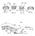
- Fig. 1 (A + B) shows a driving system structure 10, namely a truss 10A of a still unfinished escalator with a balustrade 10B.
- the driving system structure 10 has a downwardly pointing foot or transport foot 20, which is accommodated in a foot receptacle 220.
- the foot 20 and the foot receptacle 220 essentially form a lifting system 20/220 according to the invention.
- the foot 20 and thus the adjacent to him area of the driving system structure 10th can be moved up and down in the direction of the arrows 0 and U relative to the foot receptacle 220.
- FIG. 1 (A + B) shown lifting system 20/220 is stationary and can be located, for example, at an unspecified assembly station 410 of a mounting location 400, the show Fig. 2A and Fig. 2B two essentially identical lifting systems 20/220 acting as a pair, in Fig. 2B left and right, on a mobile receiving unit of a driving system transport device or a Fahrsystemaufillons 200 are arranged.
- Fig. 1 (A + B) shown foot 20 is wedge-shaped or round and has two opposing, downwardly tapering foot surfaces 22, which together include a foot angle W1. These tapered foot surfaces 22 are connected by two further, parallel, vertical foot surfaces.
- the foot can be cylindrical, round, spherical, spherical or prismatic.
- the space for the foot 20 is laterally through the opposing wings 222 and FIGS. 3A and 3D bounded by opposing side plates 224 which are disposed between the airfoils 222.
- the inclined foot surfaces 22 abut against the airfoils 222, and one of the vertical airfoils abuts a side plate 224 as long as the foot 20 is received in the foot receptacle 220.
- the inclined arrangement of the support surfaces 222 facilitates the sinking of the foot 20 into the foot receptacle 220, so that the support surfaces 222 in this case exert a centering effect.
- the Fig. 3A to 3D show details of the foot 220 of the lifting system 20/220.
- the show Figs. 3B and 3C two wedge bodies 232, which are arranged symmetrically with respect to a vertical center plane.
- Each of the wedge bodies 232 has a wedge surface 230 as the upper boundary surface.
- On the wings 222 the complementarily shaped or round, spherical or cambered or tonnig shaped and arranged foot surfaces 22 of the foot 20 come to rest.
- the wings 222 include the angle W1. This angle W1 can also be enclosed by the foot surfaces 22.
- the wedge bodies 232 are formed and arranged symmetrically to a horizontal plane. They have an upper boundary surface or wedge surface 230, and they have a lower boundary surface 242.
- the wedge bodies 232 rest on sliding surfaces 252 of a base element 250.
- the sliding surfaces 252 are complementary, that is arranged with the same inclination angle to a horizontal plane as the lower boundary surfaces 242.
- a screw device 260 serves to move the wedge body 232 and thus the wedge surfaces 230 horizontally.
- the wedge surfaces 230 maintain their symmetrical arrangement relative to the vertical center plane, so that no lateral displacement of the foot 20 and thus the driving system structure 10 occurs.
- the wedge bodies 232 approach each other and the wedge surface 230 slides upwardly, with the downwardly tapered foot surfaces 22 on the wings 222 relative to each other performing a stationary or no movement in which the foot 20 and thus the ride system structure 10 are raised becomes. Accordingly, the lower boundary surfaces 242 and the sliding surfaces 252 of the base member 250 perform a sliding relative movement.
- the reverse sliding movements ie the wedge body 232 are removed from each other and the foot 20 is lowered down.
- Tension springs 270 are arranged laterally and serve to produce a uniform bias of the arrangement with the wedge bodies 232. In addition, the extension springs 270 facilitate the downward sliding of the wedge bodies 232 on the base 250.
- Both wedge surfaces 230 are to be made of a particularly slip-friendly material, with suitable materials for the wedge bodies 232 being, for example, brass or bronze or other coated materials having similar properties.
- the sliding surfaces must usually be lubricated with a suitable lubricant such as grease or lubricating oil.
- the Fahrsystemetz choir 200 according to the invention is in the Fig. 2A to 2B shown.
- FIGS. 4A and 4B show an intermediate product 300 according to the invention, with a driving system sensor and a driving system structure.
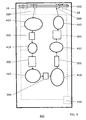
- Fig. 5 shows an assembly site 400 according to the invention, wherein from this Fig. 5 Also the method according to the invention can be seen.
- the mounting location is 400 during a transfer phase.
- the assembly site 400 includes a plurality of assembly stations 410 configured to perform station-specific, different assembly steps, wherein each assembly step may include substeps.
- the assembly station 410 also includes a plurality of driving system receivers 200 and a control system 430 that controls the operations in the assembly station 400 fully or partially automated.
- a hoist 420 such as a gantry crane or bridge crane, serves to lower the driving system structures 10 into the driving system receivers 200 and to remove them from the driving system receivers. Further hoists are not necessary, so that the mounting location requires no complex building structures.
- a first driving system pickup 200 in Fig. 5 shown at the top left is provided to receive a ride system structure 10. Further driving system receivers 200 have already picked up driving system structures 10 and together with them form intermediate products 300.
- the intermediates 300 are conveyed during the transfer phases by means of the autonomously movable driving system receivers 200 in the direction of the arrows to the individual assembly stations 410 or moved away therefrom.
- the intermediates 300 can be both longitudinally and transversely thereto, as between the in Fig. 5 below shown assembly stations to be transferred.
- the intermediates 300 are stationary in the assembly stations 410.
- the driving system structure 200 is removed from the respectively finished intermediate product 300, which can be done with the aid of the already mentioned hoist, as described in US Pat Fig. 5 shown on the top right.
- the control system 430 shown symbolically with dash-dotted lines, serves to control the entire process of complete assembly.
- the control system 430 may also include only parts of the mounting location, for example one or more or not all assembly stations.
Landscapes
- Engineering & Computer Science (AREA)
- Chemical & Material Sciences (AREA)
- Combustion & Propulsion (AREA)
- Transportation (AREA)
- Mechanical Engineering (AREA)
- Escalators And Moving Walkways (AREA)
- Automatic Assembly (AREA)
Description
Die Erfindung betrifft ein Hubsystem für eine Vertikaljustierung einer Fahrsystemstruktur und eine Verwendung des Hubsystems zum Montieren und/oder Fertigungsmontieren von Fahrsystemen. Fertigungsmontage ist definiert als Zusammenbau von diversen Einzelteilen und Baugruppen einer Fahrtreppe bzw. eines Fahrsteiges.The invention relates to a lifting system for a vertical adjustment of a driving system structure and a use of the lifting system for mounting and / or manufacturing assembly of driving systems. Production assembly is defined as assembly of various individual parts and assemblies of an escalator or a moving walkway.
Hubsysteme im Sinne der Erfindung werden benutzt, um Fahrsystemstrukturen in Montagestationen niveaumässig auszurichten. Unter dem Begriff einer Fahrsystemstruktur soll ein Fahrsystem, das heisst eine Fahrtreppe oder ein Fahrsteig, in unfertigem Zustand während seiner werkseitigen Fertigungsmontage bzw. komplett Montage verstanden werden, wobei es sich zum Beispiel um einen Rahmen oder ein Fachwerk handeln kann, das während der Fertigungsmontage mit weiteren Elementen und Baugruppen bzw. Fertigungsteilen bestückt wird.Lifting systems according to the invention are used to level drive system structures in assembly stations. The term driving system structure is intended to mean a driving system, that is to say an escalator or a moving walk, in unfinished state during its factory production assembly or complete assembly, which may be, for example, a frame or a truss during manufacture assembly other elements and assemblies or production parts is fitted.
Bei der Fertigungsmontage kann es von Bedeutung sein, dass die Fahrsystemstruktur genau horizontiert bzw. genauestens in der Waage ist.During production assembly, it may be important that the drive system structure is precisely leveled or precisely in the balance.
Ein Hubsystem, das bei der Fertigungsmontage von Fahrsystemstrukturen für eine Höhenjustierung verwendbar ist, kann zum Beispiel so ausgebildet sein, dass es mehrere Füsse aufweist, von denen jeder in einer Fussaufnahmen aufgenommen ist. Jeder Fuss stützt sich auf eine tragende Fläche auf. Um eine Höhenjustierung vorzunehmen, wird die tragende Fläche angehoben oder abgesenkt.For example, a lift system useful in manufacturing assembly of ride system structures for height adjustment may be configured to include a plurality of Has feet, each of which is recorded in a foot shots. Each foot rests on a supporting surface. To make a height adjustment, the supporting surface is raised or lowered.
Die hierbei hauptsächlich auftretenden Probleme sind die Folgenden:
- Erstens muss das Hubsystem eine möglichst perfekte Horizontrierung bzw. Höhenjustierung im Bereich von einigen Millimetern oder Zentimetern gewährleisten.
- Zweitens sind die Fahrsystemstrukturen sperrig und schwer, so dass an das Hubsystem hohe mechanische Anforderungen gestellt werden müssen.
- Drittens sollten die Hubsysteme rasch beschickbar und rasch und einfach zu bedienen sein. Die werkseitige Fertigungsmontage von Fahrsystemen kann nämlich stark rationalisiert werden, wenn sie in einer Fertigungsstrasse erfolgt. Eine solche Fertigungsstrasse umfasst mehrere Montagestationen, die von den Fahrsystemstrukturen nacheinander durchlaufen werden und gleichzeitig beschickt werden. In jeder Montagestation werden während einer Montagephase stationsspezifische Montageschritte durchgeführt. Nach Beendigung der möglichst synchron durchgeführten Montagephase werden die Fahrsystemstrukturen während einer Transportphase zur jeweils folgenden Montagestation gebracht, wobei unter optimalen Fabrikationsbedingungen auch der Transport aller Fahrsystemstrukturen möglichst synchron vor sich gehen sollte. Es ist offensichtlich, dass eine rasche Beschickung und Bedienung der Hubsysteme die Manipulationszeiten stark verkürzt.
- Viertens sollen die Hubsysteme preisgünstig sein, da eine Vielzahl von ihnen, nämlich mehrere Hubsysteme für jede Montagestation, benötigt werden.
- Firstly, the lifting system must ensure the most perfect possible horizontal or height adjustment in the range of a few millimeters or centimeters.
- Second, the driving system structures are bulky and heavy, requiring high mechanical demands on the lifting system.
- Third, the lifting systems should be quick to load and quick and easy to use. The factory production assembly of driving systems can be greatly streamlined, if it takes place in a production line. Such a production line comprises a plurality of assembly stations, which are run through by the driving system structures in succession and fed simultaneously. In each assembly station station-specific assembly steps are performed during an assembly phase. After completion of the synchronous as possible carried out assembly phase, the driving system structures are brought during a transport phase to the respective following assembly station, under optimal manufacturing conditions and the transport of all driving system structures should go as synchronously as possible. It is obvious that a quick loading and operation of the lifting systems greatly reduces the manipulation times.
- Fourth, the lifting systems should be inexpensive, since a large number of them, namely several lifting systems for each assembly station, are needed.
Zwar ist aus der
Die gattungsbildende
Ein Hubsystem, mit welchem die weiter oben erwähnten Probleme gelöst werden können, ist nicht bekannt.A lifting system with which the above-mentioned problems can be solved is not known.
Die Aufgabe der Erfindung wird somit darin gesehen,
- ein Hubsystem zu schaffen, das sich für den Einsatz bei der Fertigungsmontage von Fahrsystemstrukturen eignet
- eine Verwendung zur Durchführung einer derartigen Fertigungsmontage vorzuschlagen.
- To create a lifting system that is suitable for use in the manufacturing assembly of driving system structures
- to propose a use for carrying out such a production assembly.
Die Lösung dieser Aufgabe erfolgt erfindungsgemäss
- für das Hubsystem durch die Merkmale des Patentanspruchs 1,
- für die Verwendung durch die Merkmale des
Patentanspruchs 10.
- for the lifting system by the features of claim 1,
- for use by the features of
claim 10.
Vorteilhafte Weiterbildungen des erfindungsgemässen Hubsystems sind durch die abhängigen Patentansprüche definiert.Advantageous developments of the inventive lifting system are defined by the dependent claims.
Das neue Hubsystem umfasst einen Fuss, der mindestens während der Zusammenbauphase starr am Fahrsystem angebracht ist und während der Fertigungsmontage nach unten weist, sowie eine Fussaufnahme, in welcher der Fuss aufnehmbar bzw. in den Montagestationen aufgenommen ist. Der Fuss kann zylindrisch, rund, kugelig, ballig oder prismatisch stein. Dieser Fuss kann beilspielsweise an gegenüberliegenden Seiten durch zwei Fussflächen begrenzt werden, die unter einem Fussflächenwinkel zueinander angeordnet sind. Der Fuss kann also in einem Vertikalschnitt prismatisch sein. Die Fussaufnahme weist in diesem Fall zwei Tragflächen auf, an denen die Fussflächen anliegen. Diese Tragflächen sind komplementär zu den Fussflächen, nämlich ebenfalls prismatisch, ausgebildet und angeordnet. Die Tragflächen sind vertikal verschiebbar. Bei der Verschiebung der Tragflächen ändert der Fuss seine absolute Höhenlage, wodurch die Vertikaljustierung erfolgt.The new lifting system includes a foot that is rigidly attached to the driving system at least during the assembly phase and facing down during manufacturing assembly, and a foot receptacle in which the foot is receivable or received in the assembly stations. The foot can be cylindrical, round, spherical, spherical or prismatic stone. This foot can be limited, for example, on opposite sides by two foot surfaces, which are arranged at an angle to each other. So the foot can be prismatic in a vertical section. The foot receptacle in this case has two wings on which rest the foot surfaces. These wings are complementary to the foot surfaces, namely also prismatic, formed and arranged. The wings are vertically displaceable. When the wings are moved, the foot changes its absolute height, which causes the vertical adjustment.
Um bei der Höhenjustierung eine seitliche Verschiebung einer vertikalen Fussachse zu vermeiden, ist vorgesehen, dass die beiden Tragflächen der Fussaufnahme spiegelsymmetrisch zu einer Vertikalmittelebene angeordnet und vorzugsweise relativ zu dieser Vertikalmittelebene horizontal verschiebbar sind.In order to avoid a lateral displacement of a vertical foot axis in the height adjustment, it is provided that the two support surfaces of the foot receptacle are arranged mirror-symmetrically to a vertical center plane and preferably are horizontally displaceable relative to this vertical center plane.
Bei einer vorteilhaften Ausbildung des Hubsystems bildet die Tragfläche eine obere Begrenzungsfläche eines Keilelementes. Dieses Keilelement besitzt eine untere Begrenzungsfläche, mit der es auf einer Gleitfläche eines Grundkörpers verschiebbar abgestützt ist.In an advantageous embodiment of the lifting system, the support surface forms an upper boundary surface of a wedge element. This wedge member has a lower boundary surface with which it is slidably supported on a sliding surface of a base body.
Die untere Begrenzungsfläche des Keilkörpers steht vorteilhaft unter einem Keilwinkel zu einer Horizontalebene, so dass die obere Begrenzungsfläche und die untere Begrenzungsfläche des Keilkörpers spiegelsymmetrisch zu einer Horizontalebene gerichtet sind.The lower boundary surface of the wedge body is advantageously at a wedge angle to a horizontal plane, so that the upper boundary surface and the lower boundary surface of the wedge body are directed mirror-symmetrically to a horizontal plane.
Zur Verschiebung der Tragflächen bzw. der Keilkörper kann das Hubsystem eine mechanische Anordnung, insbesondere eine Schraubenanordnung aufweisen.For displacement of the wings or the wedge body, the lifting system may have a mechanical arrangement, in particular a screw arrangement.
Die Schraubenanordnung kann zum Beispiel eine Zentralschraube aufweisen, und diese kann mittels eines Gabel-, Ring- oder Steckschlüssels oder eines elektrisch oder hydraulisch oder per Pressluft betätigbaren Schlüssels betätigbar sein bzw. betrieben werden.The screw arrangement may, for example, have a central screw, and this may be actuated by means of a fork, ring or socket wrench or an electrically or hydraulically or by compressed air actuated key.
Im Weiteren kann das Hubsystem eine Federanordnung aufweisen, um die Tragflächen der Fussaufnahme auf den Fuss vorzuspannen und die Betätigung des Hubsystems zu erleichtern.Furthermore, the lifting system may comprise a spring arrangement to bias the wings of the foot receptacle on the foot and to facilitate the operation of the lifting system.
Um den Fuss sicher in der Fussaufnahme zu halten, kann die Fussaufnahme zwei einander gegenüberliegende vertikale Seitenplatten besitzt, die zusammen mit den Tragflächen einen Raum für den Fuss begrenzen.To hold the foot securely in the foot receptacle, the foot receptacle may have two opposing vertical side plates which together with the wings define a space for the foot.
Das Hubsystem weist üblicherweise weitere Füsse und Fussaufnahmen, insgesamt zum Beispiel drei oder vier Füsse und Fussaufnahmen auf.The lifting system usually has more feet and foot shots, for example, three or four feet and foot shots.
Weitere Einzelheiten und Vorteile der Erfindung werden im Folgenden an Hand eines Beispieles und mit Bezug auf die Zeichnungen beschrieben. Es zeigen:
- Fig. 1A
- ein Zwischenprodukt, umfassend ein stationäres Hubsystem mit einem Bereich einer auf ihm abgestützten Fahrtreppe, von der Seite;
- Fig. 1B
- den in
Fig. 1A eingekreisten Bereich, in gegenüberFig. 1A vergrösserter Darstellung; - Fig. 2A
- einen Fahrsystemaufnehmer mit zwei Hubsystemen, von denen nur eines sichtbar ist, wobei das Hubsystem auf einer mobilen Aufnahmeeinheit des Fahrsystemaufnehmers angeordnet ist, von der Seite;
- Fig. 2B
- die in
Fig. 2A dargestellten, auf der Aufnahmeeinheit des Fahrsystemaufnehmers angebrachten Hubsysteme, von vorne; - Fig. 3A
- ein Hubsystem nach der Erfindung in einer oberen Lage, von vorne;
- Fig. 3B
- das in
Fig. 3A gezeigte Hubsystem in der oberen Lage, von der Seite; - Fig. 3C
- das in den
Fig. 3A und 3B gezeigte Hubsystem in einer unteren Lage, von der Seite; - Fig. 3D
- das in den
Fig. 3A bis 3C gezeigte Hubsystem in der unteren Lage, von vorne; - Fig. 4A
- ein Zwischenprodukt nach der Erfindung;
- Fig. 4B
- den in
Fig. 4A eingekreisten Bereich in gegenüberFig. 4A vergrösserter Darstellung; und - Fig. 5
- einen Montagestandort nach der Erfindung.
- Fig. 1A
- an intermediate product comprising a stationary lifting system with an area of escalator supported thereon, from the side;
- Fig. 1B
- the in
Fig. 1A circled area, in oppositeFig. 1A enlarged view; - Fig. 2A
- a driving system pick-up with two lifting systems, only one of which is visible, the lifting system being arranged on a mobile receiving unit of the driving system pick-up, from the side;
- Fig. 2B
- in the
Fig. 2A shown, mounted on the receiving unit of Fahrsystemaufnehmers lifting systems, from the front; - Fig. 3A
- a lifting system according to the invention in an upper position, from the front;
- Fig. 3B
- this in
Fig. 3A shown lifting system in the upper position, from the side; - Fig. 3C
- that in the
FIGS. 3A and 3B shown lifting system in a lower position, from the side; - Fig. 3D
- that in the
Figs. 3A to 3C shown lifting system in the lower position, from the front; - Fig. 4A
- an intermediate of the invention;
- Fig. 4B
- the in
Fig. 4A circled area in oppositeFig. 4A enlarged view; and - Fig. 5
- a mounting location according to the invention.
Während das in
Der nur in
Der Raum für den Fuss 20 ist seitlich durch die einander gegenüberstehenden Tragflächen 222 und gemäss
The space for the
Durch die geneigte Anordnung der Tragflächen 222 wird das Einsenken des Fusses 20 in die Fussaufnahme 220 erleichtert, so dass die Tragflächen 222 hierbei eine zentrierende Wirkung ausüben.The inclined arrangement of the support surfaces 222 facilitates the sinking of the
Die
Eine Schraubenvorrichtung 260, bzw. im vorliegenden Fall eine einzige Zentralschraube, dient dazu, die Keilkörper 232 und damit die Keilflächen 230 horizontal zu verschieben. Hierbei behalten die Keilflächen 230 ihre symmetrische Anordnung relativ zur Vertikalmittelebene bei, so dass keine seitliche Verschiebung des Fusses 20 und damit der Fahrsystemstruktur 10 eintritt.A
Beim Anziehen der Schraubenvorrichtung 260 nähern sich die Keilkörper 232 einander und die Keilfläche 230 gleitet aufwärts, wobei die nach unten zulaufenden Fussflächen 22 auf den Tragflächen 222 relativ zueinander eine ruhende oder keine Bewegung ausführt, bei welcher der Fuss 20 und somit die Fahrsystemstruktur 10 angehoben wird. Entsprechend führen auch die unteren Begrenzungsflächen 242 und die Gleitflächen 252 des Grundelementes 250 eine gleitende Relativbewegung durch. Beim Lockern der Schraubenvorrichtung 260 erfolgen die umgekehrten Gleitbewegungen, das heisst die Keilkörper 232 entfernen sich voneinander und der Fuss 20 senkt sich nach unten ab.As the
Zugfedern 270 sind seitlich angeordnet und dienen dazu, eine gleichmässige Vorspannung der Anordnung mit den Keilkörpern 232 zu erzeugen. Ausserdem erleichtern die Zugfedern 270 das Abwärtsgleiten der Keilkörper 232 am Grundelement 250.Tension springs 270 are arranged laterally and serve to produce a uniform bias of the arrangement with the
Beide Keilflächen 230 sind aus einem besonders gleitfreundlichen Material herzustellen, wobei sich als geeignetes Material für die Keilkörper 232 zum Beispiel Messing oder Bronze oder andere, beschichtete Materialien mit ähnlichen Eigenschaften erwiesen haben.Both wedge surfaces 230 are to be made of a particularly slip-friendly material, with suitable materials for the
Die aneinander gleitenden Flächen müssen üblicherweise mit einem geeigneten Schmiermittel wie Schmierfett oder Schmieröl geschmiert werden.The sliding surfaces must usually be lubricated with a suitable lubricant such as grease or lubricating oil.
Der Fahrsystemaufnehmer 200 nach der Erfindung ist in den
Die
Ein erster Fahrsystemaufnehmer 200, in
Claims (10)
- Lifting system (20/220) for vertical adjustment of a transportation system structure (10), which lifting system (20/220) has a vertically displaceable supporting surface (222) on which the transportation system structure (10) can be laid,
characterized in that
during assembly of the transportation system structure (10) the latter is provided with a downwardly pointing foot or positioning piece (20), in that the supporting surface (222) serves as foot receptacle (220), in that the foot (20) has at least one foot surface or positioning piece surface (22), in that the foot cradle (220) has two supporting surfaces (222), and in that the two supporting surfaces (222) of the foot cradle (220) are arranged mirror-symmetrical to a vertical central plane and are vertically displaceable relative to this vertical central plane, the supporting surfaces (222) being embodied complementary to the foot surfaces (22), and the latter resting against the supporting surfaces (222) . - Lifting system (20/220) according to Claim 1,
characterized in that
the foot cradle (220) has at least one wedge element (232) which has a lower bounding surface (242) with which it is movably supported on a sliding surface (252) of a base element (250) . - Lifting system (20/220) according to Claim 3,
characterized in that
the wedge body has an upper bounding surface or wedge surface (230) which is arranged at a wedge angle to a horizontal plane in such manner that the upper bounding surface (230) and the lower bounding surface (242) of the wedge body (232) are arranged mirror-symmetrical to the horizontal plane. - Lifting system (20/220) according to one of the foregoing claims,
characterized in that
it has a screw arrangement (260) by means of which the wedge surface (230) is horizontally movable. - Lifting system (20/220) according to Claim 4,
characterized in that
the screw arrangement (260) has a central screw which is actuatable by means of a wrench, or by means of an electrically or hydraulically or pneumatically actuatable wrench. - Lifting system (20/220) according to one of the foregoing claims,
characterized in that
it has a spring arrangement (270) by means of which the supporting surfaces (222) of the foot cradle (220) are pretensioned in the vertical direction. - Lifting system (20/220) according to one of the foregoing claims,
characterized in that
the foot cradle (220) has two side plates (224) lying opposite to each other, which together with the supporting surfaces (222) bound a space for the foot (20) . - Lifting system (20/220) according to one of the foregoing claims,
characterized in that
the foot (20) is so formed and arranged that it can be cradled by a foot cradle (220) of a cradle unit of a transportation system cradle (200) so as to serve as transport foot. - Lifting system (20/220) according to one of the foregoing claims,
characterized in that
it has preferably one, two, or three further feet (20) and foot cradles (220) . - Use of the lifting system according to one of claims 1-9 for the assembly and/or manufacturing assembly of transportation systems, in which, from one transportation system structure (10) of a transportation system and one transportation system cradle (200) with at least one lifting system (20/220) respectively an intermediate product (300) is formed, the intermediate products (300) pass sequentially, rhythmically, and simultaneously through an assembly plant (400), during the transfer phases each of the intermediate products (300) is transferred between one of the assembly stations (410) and the respective subsequent assembly station (410), and during the assembly phases in the respective assembly stations (410) a station-specific assembly step is executed on the transportation system structures (10) of the intermediate products (300), and preferably a control system (430) of the assembly plant (400) maintains the respective assembly phases and/or transfer phases at least approximately equal with respect to time, and controls the transfer of the intermediate products (300).
Priority Applications (2)
| Application Number | Priority Date | Filing Date | Title |
|---|---|---|---|
| EP06125373A EP1795489B1 (en) | 2005-12-07 | 2006-12-05 | Lifting system. |
| PL06125373T PL1795489T3 (en) | 2005-12-07 | 2006-12-05 | Lifting system. |
Applications Claiming Priority (3)
| Application Number | Priority Date | Filing Date | Title |
|---|---|---|---|
| EP05111810 | 2005-12-07 | ||
| EP06112650 | 2006-04-13 | ||
| EP06125373A EP1795489B1 (en) | 2005-12-07 | 2006-12-05 | Lifting system. |
Publications (2)
| Publication Number | Publication Date |
|---|---|
| EP1795489A1 EP1795489A1 (en) | 2007-06-13 |
| EP1795489B1 true EP1795489B1 (en) | 2010-09-22 |
Family
ID=37887983
Family Applications (1)
| Application Number | Title | Priority Date | Filing Date |
|---|---|---|---|
| EP06125373A Active EP1795489B1 (en) | 2005-12-07 | 2006-12-05 | Lifting system. |
Country Status (2)
| Country | Link |
|---|---|
| EP (1) | EP1795489B1 (en) |
| PL (1) | PL1795489T3 (en) |
Cited By (2)
| Publication number | Priority date | Publication date | Assignee | Title |
|---|---|---|---|---|
| WO2017153314A1 (en) | 2016-03-10 | 2017-09-14 | Inventio Ag | Device for the robot-assisted production of a support structure for a passenger transport system |
| WO2017153324A1 (en) | 2016-03-10 | 2017-09-14 | Inventio Ag | Method for robot-assisted production of a support structure for a passenger transport system |
Families Citing this family (1)
| Publication number | Priority date | Publication date | Assignee | Title |
|---|---|---|---|---|
| US9440820B2 (en) | 2015-01-09 | 2016-09-13 | Kone Coporation | Escalator lifting frame and method of using the same |
Family Cites Families (5)
| Publication number | Priority date | Publication date | Assignee | Title |
|---|---|---|---|---|
| US3137512A (en) * | 1961-08-11 | 1964-06-16 | Carpezzi Leo Joseph | Height adjustable dolly |
| JPH07315740A (en) * | 1994-05-24 | 1995-12-05 | Hitachi Building Syst Eng & Service Co Ltd | Carrying out method for escalator truss |
| JPH11199165A (en) * | 1998-01-14 | 1999-07-27 | Hitachi Building Systems Co Ltd | Escalator frame moving method across staircase |
| CA2280414C (en) * | 1999-08-03 | 2000-10-31 | Honda Canada Inc. | Zone inspection manufacturing line |
| DE10041578A1 (en) * | 2000-08-24 | 2002-03-21 | Markus Helling | chassis system |
-
2006
- 2006-12-05 EP EP06125373A patent/EP1795489B1/en active Active
- 2006-12-05 PL PL06125373T patent/PL1795489T3/en unknown
Cited By (4)
| Publication number | Priority date | Publication date | Assignee | Title |
|---|---|---|---|---|
| WO2017153314A1 (en) | 2016-03-10 | 2017-09-14 | Inventio Ag | Device for the robot-assisted production of a support structure for a passenger transport system |
| WO2017153324A1 (en) | 2016-03-10 | 2017-09-14 | Inventio Ag | Method for robot-assisted production of a support structure for a passenger transport system |
| US10562133B2 (en) | 2016-03-10 | 2020-02-18 | Inventio Ag | Method for a robot-assisted assembly of a supporting structure for a passenger transport system |
| US11407051B2 (en) | 2016-03-10 | 2022-08-09 | Inventio Ag | Device for the robot-assisted manufacturing of a supporting structure for a passenger transport system |
Also Published As
| Publication number | Publication date |
|---|---|
| EP1795489A1 (en) | 2007-06-13 |
| PL1795489T3 (en) | 2011-03-31 |
Similar Documents
| Publication | Publication Date | Title |
|---|---|---|
| EP2792431B1 (en) | Machining system for structural components of aircraft | |
| EP1780167B1 (en) | Mobile crane with counterweight | |
| DE69321786T2 (en) | Mobile crane with device for attaching the counterweight | |
| DE69815902T2 (en) | Counterweight handling device for slewing cranes | |
| WO2007056969A1 (en) | Large mobile crane | |
| EP0469182A2 (en) | Device for lifting, lowering and the water carriage of heavy loads | |
| DE2611468C2 (en) | Method for lifting loads and device for carrying out the method | |
| EP1795489B1 (en) | Lifting system. | |
| DE1808989C3 (en) | Device for the production of monolithic reinforced concrete room cells with one open side pointing downwards, in particular prefabricated garages, under the corridor | |
| EP1795488B1 (en) | Pick-up device for travelling system. | |
| DE102011120408A1 (en) | Load lifting device for lifting tripod foundation structure of wind-power plant to transport structure to port, has bolts moved after approximation of load lifting part to abutment parts to couple lifting part with abutment parts | |
| DE69001231T2 (en) | DEVICE AND METHOD FOR PICKING UP AND MOVING OBJECTS. | |
| DE3608096C2 (en) | ||
| DE19900688A1 (en) | Crane system with esp. lifting beams to move loads on rails has automatic transfer handler to move load lifting beam loads at lower level without crane | |
| EP2921563A1 (en) | Device for vertically raising and/or lowering a metallurgical container, assembly with such a device and method | |
| EP3904270B1 (en) | Lifting device and method for extracting a mast or support anchored in a foundation | |
| DE8423632U1 (en) | Device for replacing worn electrolysis cells | |
| DE1658602B1 (en) | Device for assembling the prefabricated components of a prestressed concrete bridge, each comprising a complete bridge section, in cantilevered cantilevered sections | |
| EP1661843B2 (en) | Method for transferring a heavy load and lifting accessories for a lifting apparatus | |
| WO1989003795A1 (en) | Device for lifting loads | |
| DE10245438B4 (en) | Method for removing a heavy load, in particular a container containing activated primary circuit components, from the reactor building of a nuclear power plant | |
| EP1170189B1 (en) | Track system for a workshop | |
| DE2136401C3 (en) | Device for room-sized structures made of reinforced concrete standing on a formwork frame | |
| DE3634546A1 (en) | Device for lifting load bodies | |
| DE102016216768A1 (en) | manufacturing device |
Legal Events
| Date | Code | Title | Description |
|---|---|---|---|
| PUAI | Public reference made under article 153(3) epc to a published international application that has entered the european phase |
Free format text: ORIGINAL CODE: 0009012 |
|
| AK | Designated contracting states |
Kind code of ref document: A1 Designated state(s): AT BE BG CH CY CZ DE DK EE ES FI FR GB GR HU IE IS IT LI LT LU LV MC NL PL PT RO SE SI SK TR |
|
| AX | Request for extension of the european patent |
Extension state: AL BA HR MK YU |
|
| 17P | Request for examination filed |
Effective date: 20071211 |
|
| AKX | Designation fees paid |
Designated state(s): AT BE BG CH CY CZ DE DK EE ES FI FR GB GR HU IE IS IT LI LT LU LV MC NL PL PT RO SE SI SK TR |
|
| 17Q | First examination report despatched |
Effective date: 20080225 |
|
| REG | Reference to a national code |
Ref country code: HK Ref legal event code: DE Ref document number: 1107688 Country of ref document: HK |
|
| GRAP | Despatch of communication of intention to grant a patent |
Free format text: ORIGINAL CODE: EPIDOSNIGR1 |
|
| GRAS | Grant fee paid |
Free format text: ORIGINAL CODE: EPIDOSNIGR3 |
|
| GRAA | (expected) grant |
Free format text: ORIGINAL CODE: 0009210 |
|
| AK | Designated contracting states |
Kind code of ref document: B1 Designated state(s): AT BE BG CH CY CZ DE DK EE ES FI FR GB GR HU IE IS IT LI LT LU LV MC NL PL PT RO SE SI SK TR |
|
| REG | Reference to a national code |
Ref country code: GB Ref legal event code: FG4D Free format text: NOT ENGLISH |
|
| REG | Reference to a national code |
Ref country code: CH Ref legal event code: EP |
|
| REG | Reference to a national code |
Ref country code: IE Ref legal event code: FG4D Free format text: LANGUAGE OF EP DOCUMENT: GERMAN |
|
| REF | Corresponds to: |
Ref document number: 502006007918 Country of ref document: DE Date of ref document: 20101104 Kind code of ref document: P |
|
| REG | Reference to a national code |
Ref country code: RO Ref legal event code: EPE |
|
| REG | Reference to a national code |
Ref country code: NL Ref legal event code: T3 |
|
| REG | Reference to a national code |
Ref country code: HK Ref legal event code: GR Ref document number: 1107688 Country of ref document: HK |
|
| PG25 | Lapsed in a contracting state [announced via postgrant information from national office to epo] |
Ref country code: LT Free format text: LAPSE BECAUSE OF FAILURE TO SUBMIT A TRANSLATION OF THE DESCRIPTION OR TO PAY THE FEE WITHIN THE PRESCRIBED TIME-LIMIT Effective date: 20100922 |
|
| REG | Reference to a national code |
Ref country code: ES Ref legal event code: FG2A Effective date: 20110214 |
|
| LTIE | Lt: invalidation of european patent or patent extension |
Effective date: 20100922 |
|
| PG25 | Lapsed in a contracting state [announced via postgrant information from national office to epo] |
Ref country code: SI Free format text: LAPSE BECAUSE OF FAILURE TO SUBMIT A TRANSLATION OF THE DESCRIPTION OR TO PAY THE FEE WITHIN THE PRESCRIBED TIME-LIMIT Effective date: 20100922 |
|
| PG25 | Lapsed in a contracting state [announced via postgrant information from national office to epo] |
Ref country code: LV Free format text: LAPSE BECAUSE OF FAILURE TO SUBMIT A TRANSLATION OF THE DESCRIPTION OR TO PAY THE FEE WITHIN THE PRESCRIBED TIME-LIMIT Effective date: 20100922 Ref country code: GR Free format text: LAPSE BECAUSE OF FAILURE TO SUBMIT A TRANSLATION OF THE DESCRIPTION OR TO PAY THE FEE WITHIN THE PRESCRIBED TIME-LIMIT Effective date: 20101223 Ref country code: SE Free format text: LAPSE BECAUSE OF FAILURE TO SUBMIT A TRANSLATION OF THE DESCRIPTION OR TO PAY THE FEE WITHIN THE PRESCRIBED TIME-LIMIT Effective date: 20100922 |
|
| REG | Reference to a national code |
Ref country code: PL Ref legal event code: T3 |
|
| REG | Reference to a national code |
Ref country code: SK Ref legal event code: T3 Ref document number: E 8451 Country of ref document: SK |
|
| REG | Reference to a national code |
Ref country code: IE Ref legal event code: FD4D |
|
| PG25 | Lapsed in a contracting state [announced via postgrant information from national office to epo] |
Ref country code: IE Free format text: LAPSE BECAUSE OF FAILURE TO SUBMIT A TRANSLATION OF THE DESCRIPTION OR TO PAY THE FEE WITHIN THE PRESCRIBED TIME-LIMIT Effective date: 20100922 |
|
| PG25 | Lapsed in a contracting state [announced via postgrant information from national office to epo] |
Ref country code: PT Free format text: LAPSE BECAUSE OF FAILURE TO SUBMIT A TRANSLATION OF THE DESCRIPTION OR TO PAY THE FEE WITHIN THE PRESCRIBED TIME-LIMIT Effective date: 20110124 Ref country code: IS Free format text: LAPSE BECAUSE OF FAILURE TO SUBMIT A TRANSLATION OF THE DESCRIPTION OR TO PAY THE FEE WITHIN THE PRESCRIBED TIME-LIMIT Effective date: 20110122 Ref country code: EE Free format text: LAPSE BECAUSE OF FAILURE TO SUBMIT A TRANSLATION OF THE DESCRIPTION OR TO PAY THE FEE WITHIN THE PRESCRIBED TIME-LIMIT Effective date: 20100922 |
|
| BERE | Be: lapsed |
Owner name: INVENTIO A.G. Effective date: 20101231 |
|
| PG25 | Lapsed in a contracting state [announced via postgrant information from national office to epo] |
Ref country code: MC Free format text: LAPSE BECAUSE OF NON-PAYMENT OF DUE FEES Effective date: 20101231 |
|
| PLBE | No opposition filed within time limit |
Free format text: ORIGINAL CODE: 0009261 |
|
| STAA | Information on the status of an ep patent application or granted ep patent |
Free format text: STATUS: NO OPPOSITION FILED WITHIN TIME LIMIT |
|
| 26N | No opposition filed |
Effective date: 20110623 |
|
| PG25 | Lapsed in a contracting state [announced via postgrant information from national office to epo] |
Ref country code: DK Free format text: LAPSE BECAUSE OF FAILURE TO SUBMIT A TRANSLATION OF THE DESCRIPTION OR TO PAY THE FEE WITHIN THE PRESCRIBED TIME-LIMIT Effective date: 20100922 |
|
| PG25 | Lapsed in a contracting state [announced via postgrant information from national office to epo] |
Ref country code: BE Free format text: LAPSE BECAUSE OF NON-PAYMENT OF DUE FEES Effective date: 20101231 |
|
| REG | Reference to a national code |
Ref country code: DE Ref legal event code: R097 Ref document number: 502006007918 Country of ref document: DE Effective date: 20110623 |
|
| PGFP | Annual fee paid to national office [announced via postgrant information from national office to epo] |
Ref country code: NL Payment date: 20111228 Year of fee payment: 6 |
|
| PG25 | Lapsed in a contracting state [announced via postgrant information from national office to epo] |
Ref country code: CY Free format text: LAPSE BECAUSE OF FAILURE TO SUBMIT A TRANSLATION OF THE DESCRIPTION OR TO PAY THE FEE WITHIN THE PRESCRIBED TIME-LIMIT Effective date: 20100922 |
|
| PG25 | Lapsed in a contracting state [announced via postgrant information from national office to epo] |
Ref country code: LU Free format text: LAPSE BECAUSE OF NON-PAYMENT OF DUE FEES Effective date: 20101205 Ref country code: HU Free format text: LAPSE BECAUSE OF FAILURE TO SUBMIT A TRANSLATION OF THE DESCRIPTION OR TO PAY THE FEE WITHIN THE PRESCRIBED TIME-LIMIT Effective date: 20110323 |
|
| REG | Reference to a national code |
Ref country code: NL Ref legal event code: V1 Effective date: 20130701 |
|
| REG | Reference to a national code |
Ref country code: AT Ref legal event code: MM01 Ref document number: 482167 Country of ref document: AT Kind code of ref document: T Effective date: 20121205 |
|
| PG25 | Lapsed in a contracting state [announced via postgrant information from national office to epo] |
Ref country code: NL Free format text: LAPSE BECAUSE OF NON-PAYMENT OF DUE FEES Effective date: 20130701 Ref country code: AT Free format text: LAPSE BECAUSE OF NON-PAYMENT OF DUE FEES Effective date: 20121205 |
|
| REG | Reference to a national code |
Ref country code: FR Ref legal event code: PLFP Year of fee payment: 10 |
|
| REG | Reference to a national code |
Ref country code: FR Ref legal event code: PLFP Year of fee payment: 11 |
|
| PGFP | Annual fee paid to national office [announced via postgrant information from national office to epo] |
Ref country code: FI Payment date: 20161213 Year of fee payment: 11 |
|
| REG | Reference to a national code |
Ref country code: FR Ref legal event code: PLFP Year of fee payment: 12 |
|
| PG25 | Lapsed in a contracting state [announced via postgrant information from national office to epo] |
Ref country code: FI Free format text: LAPSE BECAUSE OF NON-PAYMENT OF DUE FEES Effective date: 20171205 |
|
| PGFP | Annual fee paid to national office [announced via postgrant information from national office to epo] |
Ref country code: FR Payment date: 20201229 Year of fee payment: 15 Ref country code: BG Payment date: 20201221 Year of fee payment: 15 Ref country code: CZ Payment date: 20201207 Year of fee payment: 15 Ref country code: CH Payment date: 20201222 Year of fee payment: 15 Ref country code: RO Payment date: 20201203 Year of fee payment: 15 Ref country code: GB Payment date: 20201228 Year of fee payment: 15 |
|
| PGFP | Annual fee paid to national office [announced via postgrant information from national office to epo] |
Ref country code: SK Payment date: 20201125 Year of fee payment: 15 |
|
| PGFP | Annual fee paid to national office [announced via postgrant information from national office to epo] |
Ref country code: IT Payment date: 20201221 Year of fee payment: 15 |
|
| PGFP | Annual fee paid to national office [announced via postgrant information from national office to epo] |
Ref country code: TR Payment date: 20201204 Year of fee payment: 15 Ref country code: PL Payment date: 20201201 Year of fee payment: 15 |
|
| REG | Reference to a national code |
Ref country code: SK Ref legal event code: MM4A Ref document number: E 8451 Country of ref document: SK Effective date: 20211205 |
|
| PG25 | Lapsed in a contracting state [announced via postgrant information from national office to epo] |
Ref country code: RO Free format text: LAPSE BECAUSE OF NON-PAYMENT OF DUE FEES Effective date: 20211205 Ref country code: CZ Free format text: LAPSE BECAUSE OF NON-PAYMENT OF DUE FEES Effective date: 20211205 |
|
| REG | Reference to a national code |
Ref country code: CH Ref legal event code: PL |
|
| GBPC | Gb: european patent ceased through non-payment of renewal fee |
Effective date: 20211205 |
|
| PG25 | Lapsed in a contracting state [announced via postgrant information from national office to epo] |
Ref country code: SK Free format text: LAPSE BECAUSE OF NON-PAYMENT OF DUE FEES Effective date: 20211205 Ref country code: GB Free format text: LAPSE BECAUSE OF NON-PAYMENT OF DUE FEES Effective date: 20211205 Ref country code: BG Free format text: LAPSE BECAUSE OF NON-PAYMENT OF DUE FEES Effective date: 20220630 |
|
| PG25 | Lapsed in a contracting state [announced via postgrant information from national office to epo] |
Ref country code: FR Free format text: LAPSE BECAUSE OF NON-PAYMENT OF DUE FEES Effective date: 20211231 |
|
| PG25 | Lapsed in a contracting state [announced via postgrant information from national office to epo] |
Ref country code: LI Free format text: LAPSE BECAUSE OF NON-PAYMENT OF DUE FEES Effective date: 20211231 Ref country code: CH Free format text: LAPSE BECAUSE OF NON-PAYMENT OF DUE FEES Effective date: 20211231 |
|
| PG25 | Lapsed in a contracting state [announced via postgrant information from national office to epo] |
Ref country code: IT Free format text: LAPSE BECAUSE OF NON-PAYMENT OF DUE FEES Effective date: 20211205 |
|
| PGFP | Annual fee paid to national office [announced via postgrant information from national office to epo] |
Ref country code: ES Payment date: 20230120 Year of fee payment: 17 |
|
| PGFP | Annual fee paid to national office [announced via postgrant information from national office to epo] |
Ref country code: DE Payment date: 20221227 Year of fee payment: 17 |
|
| PG25 | Lapsed in a contracting state [announced via postgrant information from national office to epo] |
Ref country code: PL Free format text: LAPSE BECAUSE OF NON-PAYMENT OF DUE FEES Effective date: 20211205 |
|
| REG | Reference to a national code |
Ref country code: DE Ref legal event code: R119 Ref document number: 502006007918 Country of ref document: DE |