EP1795406A1 - Scheibenwischvorrichtung - Google Patents
Scheibenwischvorrichtung Download PDFInfo
- Publication number
- EP1795406A1 EP1795406A1 EP05111926A EP05111926A EP1795406A1 EP 1795406 A1 EP1795406 A1 EP 1795406A1 EP 05111926 A EP05111926 A EP 05111926A EP 05111926 A EP05111926 A EP 05111926A EP 1795406 A1 EP1795406 A1 EP 1795406A1
- Authority
- EP
- European Patent Office
- Prior art keywords
- joint part
- windscreen wiper
- wiper device
- oscillating arm
- shaped cross
- Prior art date
- Legal status (The legal status is an assumption and is not a legal conclusion. Google has not performed a legal analysis and makes no representation as to the accuracy of the status listed.)
- Granted
Links
- 210000002105 tongue Anatomy 0.000 claims description 22
- 230000000903 blocking effect Effects 0.000 claims description 3
- 239000000463 material Substances 0.000 claims description 3
- 229910000831 Steel Inorganic materials 0.000 description 3
- 239000010959 steel Substances 0.000 description 3
- 206010052904 Musculoskeletal stiffness Diseases 0.000 description 2
- 238000004026 adhesive bonding Methods 0.000 description 2
- 238000005219 brazing Methods 0.000 description 2
- 230000014759 maintenance of location Effects 0.000 description 2
- 238000005476 soldering Methods 0.000 description 2
- 238000003466 welding Methods 0.000 description 2
- 229910052782 aluminium Inorganic materials 0.000 description 1
- XAGFODPZIPBFFR-UHFFFAOYSA-N aluminium Chemical compound [Al] XAGFODPZIPBFFR-UHFFFAOYSA-N 0.000 description 1
- 238000004519 manufacturing process Methods 0.000 description 1
- 229910052751 metal Inorganic materials 0.000 description 1
- 239000002184 metal Substances 0.000 description 1
- 229920002994 synthetic fiber Polymers 0.000 description 1
Images


Classifications
-
- B—PERFORMING OPERATIONS; TRANSPORTING
- B60—VEHICLES IN GENERAL
- B60S—SERVICING, CLEANING, REPAIRING, SUPPORTING, LIFTING, OR MANOEUVRING OF VEHICLES, NOT OTHERWISE PROVIDED FOR
- B60S1/00—Cleaning of vehicles
- B60S1/02—Cleaning windscreens, windows or optical devices
- B60S1/04—Wipers or the like, e.g. scrapers
- B60S1/32—Wipers or the like, e.g. scrapers characterised by constructional features of wiper blade arms or blades
- B60S1/40—Connections between blades and arms
- B60S1/4038—Connections between blades and arms for arms provided with a channel-shaped end
-
- B—PERFORMING OPERATIONS; TRANSPORTING
- B60—VEHICLES IN GENERAL
- B60S—SERVICING, CLEANING, REPAIRING, SUPPORTING, LIFTING, OR MANOEUVRING OF VEHICLES, NOT OTHERWISE PROVIDED FOR
- B60S1/00—Cleaning of vehicles
- B60S1/02—Cleaning windscreens, windows or optical devices
- B60S1/04—Wipers or the like, e.g. scrapers
- B60S1/32—Wipers or the like, e.g. scrapers characterised by constructional features of wiper blade arms or blades
- B60S1/38—Wiper blades
- B60S1/3848—Flat-type wiper blade, i.e. without harness
- B60S1/3849—Connectors therefor; Connection to wiper arm; Attached to blade
- B60S1/3851—Mounting of connector to blade assembly
- B60S1/3856—Gripping the blade
-
- B—PERFORMING OPERATIONS; TRANSPORTING
- B60—VEHICLES IN GENERAL
- B60S—SERVICING, CLEANING, REPAIRING, SUPPORTING, LIFTING, OR MANOEUVRING OF VEHICLES, NOT OTHERWISE PROVIDED FOR
- B60S1/00—Cleaning of vehicles
- B60S1/02—Cleaning windscreens, windows or optical devices
- B60S1/04—Wipers or the like, e.g. scrapers
- B60S1/32—Wipers or the like, e.g. scrapers characterised by constructional features of wiper blade arms or blades
- B60S1/38—Wiper blades
- B60S1/3806—Means, or measures taken, for influencing the aerodynamic quality of the wiper blades
-
- B—PERFORMING OPERATIONS; TRANSPORTING
- B60—VEHICLES IN GENERAL
- B60S—SERVICING, CLEANING, REPAIRING, SUPPORTING, LIFTING, OR MANOEUVRING OF VEHICLES, NOT OTHERWISE PROVIDED FOR
- B60S1/00—Cleaning of vehicles
- B60S1/02—Cleaning windscreens, windows or optical devices
- B60S1/04—Wipers or the like, e.g. scrapers
- B60S1/32—Wipers or the like, e.g. scrapers characterised by constructional features of wiper blade arms or blades
- B60S1/40—Connections between blades and arms
- B60S1/4038—Connections between blades and arms for arms provided with a channel-shaped end
- B60S1/4045—Connections between blades and arms for arms provided with a channel-shaped end comprising a detachable intermediate element mounted on the channel-shaped end
- B60S1/4048—Connections between blades and arms for arms provided with a channel-shaped end comprising a detachable intermediate element mounted on the channel-shaped end the element being provided with retention means co-operating with the channel-shaped end of the arm
- B60S2001/4051—Connections between blades and arms for arms provided with a channel-shaped end comprising a detachable intermediate element mounted on the channel-shaped end the element being provided with retention means co-operating with the channel-shaped end of the arm the intermediate element engaging the side walls of the arm
-
- B—PERFORMING OPERATIONS; TRANSPORTING
- B60—VEHICLES IN GENERAL
- B60S—SERVICING, CLEANING, REPAIRING, SUPPORTING, LIFTING, OR MANOEUVRING OF VEHICLES, NOT OTHERWISE PROVIDED FOR
- B60S1/00—Cleaning of vehicles
- B60S1/02—Cleaning windscreens, windows or optical devices
- B60S1/04—Wipers or the like, e.g. scrapers
- B60S1/32—Wipers or the like, e.g. scrapers characterised by constructional features of wiper blade arms or blades
- B60S1/40—Connections between blades and arms
- B60S1/4038—Connections between blades and arms for arms provided with a channel-shaped end
- B60S1/4045—Connections between blades and arms for arms provided with a channel-shaped end comprising a detachable intermediate element mounted on the channel-shaped end
- B60S1/4048—Connections between blades and arms for arms provided with a channel-shaped end comprising a detachable intermediate element mounted on the channel-shaped end the element being provided with retention means co-operating with the channel-shaped end of the arm
- B60S2001/4054—Connections between blades and arms for arms provided with a channel-shaped end comprising a detachable intermediate element mounted on the channel-shaped end the element being provided with retention means co-operating with the channel-shaped end of the arm the intermediate element engaging the back part of the arm
Definitions
- the present invention relates to a windscreen wiper device comprising an elastic, elongated carrier element, as well as an elongated wiper blade of a flexible material, which can be placed in abutment with a windscreen to be wiped, which wiper blade includes opposing longitudinal grooves on its longitudinal sides, in which grooves spaced-apart longitudinal strips of the carrier element are disposed, wherein neighbouring ends of said longitudinal strips are interconnected by a respective connecting piece, which windscreen wiper device comprises a connecting device for an oscillating arm, wherein said oscillating arm is pivotally connected to said connecting device about a pivot axis near one end, with the interposition of a joint part.
- Such a windscreen wiper device is known from European patent publication no. 1 403 156 of the same Applicant.
- This prior art windscreen wiper device is designed as a "yokeless" wiper device, wherein no use is made of several yokes pivotally connected to each other, but wherein the wiper blade is biassed by the carrier element, as a result of which it exhibits a specific curvature.
- the joint part comprises at least one resilient tongue engaging in a correspondingly shaped hole provided in the oscillating arm, wherein the resilient tongue is rotatable along an hinge axis between an outward position retaining the wiper blade onto the oscillating arm and an inward position releasing the wiper blade from the oscillating arm.
- the resilient tongue In order to connect the wiper blade onto the oscillating arm, the resilient tongue is initially pushed in against a spring force - as if it were a push button - and then allowed to spring back into the hole provided in the oscillating arm, thus snapping, that is clipping the resilient tongue into the hole. By subsequently pushing in again the resilient tongue against the spring force, the wiper blade may be released from the oscillating arm.
- the object of the invention is to provide a improved windscreen wiper device.
- a windscreen wiper device of the type referred to in the introduction is characterized according to the invention in that said connecting device comprises a first part connected to said longitudinal strips, as well as a second part connected to said first part, wherein said second part and said joint part are provided with mutually cooperating pivot means for pivotally connecting said joint part to said second part.
- Said first part preferably has a flat shape and acts as a base part, wherein the first part is preferably fixedly connected to the longitudinal strips through a welding, brazing ("soldering"), glueing or clamping operation.
- said first part is a universal connection part for each type of interconnection between the wiper blade and the oscillating arm.
- a different type of said second part to be connected to said first part may be used for each different type of interconnection between the wiper blade and the oscillating arm.
- the advantage achieved by the invention is that a unit consisting of said wiper blade and said first part connected to said longitudinal strips can be manufactured for each and every type of interconnection between said wiper blade and said oscillating arm, while only a relatively cheap and easy to manufacture second part to be connected to said first part has to correspond with a specific type of interconnection between said wiper blade and said oscillating arm.
- Said second part may be connected to said first part through a welding, brazing ("soldering"), glueing or clamping operation.
- said second part is detachably connected to said first part particularly through a snapping/clipping operation.
- said second part comprises clamping means integral therewith engaging around longitudinal sides of said first part that face away from each other.
- said joint part is connected to said second part by pivotally engaging protrusions of said second part, at the location of said pivot axis, in recesses provided in said joint part.
- protrusions that function as bearing surfaces are spaced far apart, so that the forces exerted thereon will be relatively low.
- said joint part has an at least substantially U-shaped cross-section at the location of its connection to said second part, wherein said joint part in each leg of said U-shaped cross-section is provided with a recess provided coaxially with said pivot axis.
- the protrusions extend outwards on either side of said second part, wherein the protrusions are at least substantially cylindrical.
- said protrusions are at least substantially spherical or frusto-conical.
- said joint part is connected to said second part by pivotally engaging protrusions of said joint part, at the location of said pivot axis, in recesses provided in said second part.
- said joint part has an at least substantially U-shaped cross-section at the location of its connection to said second part, and wherein said joint part in each leg of said U-shaped cross-section is provided with a protrusion provided coaxially with said pivot axis.
- the protrusions preferably extend inwards on either side of said joint part, wherein the protrusions are at least substantially cylindrical.
- said protrusions are at least substantially spherical or frusto-conical.
- the recesses are correspondingly shaped.
- said joint part comprises at least one resilient tongue engaging in a correspondingly shaped hole provided in said oscillating arm, wherein said resilient tongue is rotatable along a hinge axis between an outward position retaining said wiper blade onto said oscillating arm and an inward position releasing said wiper blade from said oscillating arm.
- Said hinge axis is particularly located near an inner edge of said joint part.
- said hinge axis is located near an outer edge of said joint part, as described in European patent application no. 04103735.9 of the same Applicant.
- said resilient tongue is forced in the outward position under the influence of a moment in case a force is exerted on the wiper blade in a direction away from the oscillating arm.
- the counterforce exerted by the oscillating arm on the resilient tongue engages at a point located behind the hinge axis, seen in the direction of the force exerted on the wiper blade.
- said moment of force ensures in a natural way that the resilient tongue is forced automatically in its outward position, that is its position retaining the wiper blade onto the oscillating arm.
- said moment during use compels the resilient tongue to automatically take its inward position, thereby releasing the wiper blade from the oscillating arm, with all negative consequences involved.
- the oscillating arm has an at least substantially U-shaped cross-section at the location of its connection to said joint part, wherein said hole is provided in a base of said U-shaped cross-section.
- said joint part comprises at least two lateral resilient tongues extending outwardly, wherein the oscillating arm has an at least substantially U-shaped cross-section at the location of its connection to said joint part, and wherein each tongue engages in a correspondingly shaped hole provided in a leg of said U-shaped cross-section.
- said hole(s) has/have a closed circumference.
- Such (a) closed hole(s) enhance(s) the retention of the connection device/joint part onto the oscillating arm in all possible directions, particularly both horizontally and vertically.
- said hole(s) has/have a non-closed circumference.
- said joint part is made of plastic (including any synthetic material having some flexibility).
- said joint part comprises a recess for snappingly receiving a free end of said oscillating arm.
- a top surface of said free end of said oscillating arm is snappingly received into said recess.
- said free end of said oscillating arm is provided with a finger extending longitudinally therefrom, wherein said finger is snappingly received by said recess.
- said joint part comprises at least one protrusion extending laterally from a longitudinal side of said joint part, said protrusion hooking behind a correspondingly shaped protrusion on said oscillating arm for blocking a longitudinal movement of said wiper blade with respect to said oscillating arm.
- a resilient free end of said joint part can pivot about a hinge axis for snappingly connecting said oscillating arm to said joint part.
- FIG. 1 shows a preferred variant of a windscreen wiper device 1 according to the invention.
- Said windscreen wiper device 1 is built up of an elastomeric wiper blade 2, in the longitudinal sides of which opposing longitudinal grooves 3 are formed, and of longitudinal strips 4 made of spring band steel, which are fitted in said longitudinal grooves 3.
- Said strips 4 form a flexible carrier element for the wiper blade 2, as it were, which is thus biassed in a curved position (the curvature in operative position being that of a windscreen to be wiped).
- Neighbouring ends 5 of the strips 4 are interconnected on either side of the windscreen wiper device 1 by means of connecting pieces 6 functioning as clamping members.
- the connecting pieces 6 are separate constructional elements, which may be form-locked ("positive locking” or “having a positive fit") or force-locked to the ends 5 of the strips 4.
- said connecting pieces 6 are in one piece with the strips 4 made of spring band steel. In the latter case said connecting pieces 6 form transverse bridges for the strips 4, as it were.
- the windscreen wiper device 1 is furthermore built up of a connecting device 7 of plastic material for an oscillating arm 8.
- the connecting device 7 may also be made of metal, such as steel or aluminum.
- the connecting device 7 comprises a first flat base part 9 fixedly connected to said strips 4, as well as a second part 9' detachably connected to said first part 9.
- Said first part 9 is a universal part in the sense that it can be used for each and every type of interconnection between the wiper blade and the oscillating arm, that is, for example, for said interconnection as shown is figures 2 through 5 on the one end and for said interconnection as shown in figures 6 through 9 on the other hand.
- Said first part 9 is particularly welded, brazed ("soldered"), glued or clamped onto said strips 4.
- said second part 9' differs for each different type of interconnection between the wiper blade and the oscillating arm.
- said second part 9' is detachably connected to said first part 9 using clamping means in the form of resilient legs C integral therewith engaging around longitudinal sides of said first part 9 that face away from each other, as a result of which the second part 9' is firmly attached to the unit consisting of the first part 9, the wiper blade 2 and the strips 4.
- said downwardly extending legs C are resilient such that they can be clipped/snapped around said longitudinal sides of said first part 9, wherein each pair of legs C on one side of said wiper blade are introduced in corresponding recesses C' in said first part 9.
- the oscillating arm 8 is pivotally connected to said unit about a pivot axis near one end, as will be described hereunder.
- the second part 9' comprises two cylindrical protrusions 10 extending outwards on either side of said connecting device 7.
- said protrusions may have a spherical or frusto-conical shape.
- These protrusions 10 pivotally engage in identically shaped cylindrical recesses 11 of a plastic joint part 12.
- the recesses 11 may have a non-closed shape (i.e. open circumference).
- Said protrusions 10 act as bearing surfaces at the location of a pivot axis in order to pivot the joint part 12 (and the oscillating arm 8 attached thereto) about said pivot axis near one end of the oscillating arm 8.
- the protrusions 10 are preferably in one piece with the second part 9'; in the alternative, the protrusions 10 are part of a single pivot pin perpendicular to the second part 9'.
- Said second part 9' may be equipped with a cover or cap in order to obtain an aesthetic appearance thereof, to avoid sharp edges and to provide protection against UV-light etcetera.
- the joint part 12 comprises one resilient tongue 13 extending outwardly, while the oscillating arm 8 has an U-shaped cross-section at the location of its connection to said joint part 12, so that the tongue 13 engages in an identically shaped hole 14 provided in a base 15 of said U-shaped cross-section (figure 5).
- Figure 3 shows the steps of mounting the connecting device 7 with the wiper blade 2 onto the oscillating arm 8.
- the joint part 12 being already clipped onto the second part 9' is pivoted relative to said second part 9', so that said joint part 12 can be easily slid on a free end of the oscillating arm 8.
- the resilient tongue 13 is initially pushed in against a spring force and then allowed to spring back into said hole 14, thus snapping, that is clipping the resilient tongue 13 into the hole 14.
- This is a so-called bayonet-connection.
- the oscillating arm 8 together with the joint part 12 may then be pivoted back in a position parallel to the wiper blade 2 in order to be ready for use.
- the connecting device 7 and the joint part 2 together with the wiper blade 2 may be released from the oscillating arm 8. Dismounting the connecting device 7 with the wiper blade 2 from the oscillating arm 8 is thus realized by sliding the connecting device 7 and the joint part 2 together with the wiper blade 2 in a direction away from the oscillating arm 8.
- Each leg 16 of the U-shaped cross-section of the oscillating arm 8 comprises clamping members formed as inwardly bended edges 17 integral with said legs 16, wherein during use said edges 17 engage round longitudinal sides of said joint part 12 that face away from each other.
- an enhanced retention of the connecting device 7/joint part 12 onto the oscillating arm 8 is achieved in vertical direction, that is perpendicular to the longitudinal direction of the oscillating arm 8.
- a spoiler 19 is furthermore present being made in one piece with said wiper blade 2.
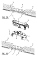
- FIGS 4, 5 and 6 correspond to figures 1, 2 and 3, respectively, but now relating to another preferred embodiment of a windscreen wiper device according to the invention, wherein corresponding parts have been designated with the same reference numerals.
- a first part 9 as shown in figures 4 through 6 is identical to the same of figures 1 through 3, so that said first part 9 is a true universal part for several types of interconnection between a wiper blade 2 and an oscillating arm 8.
- second part 9' in figures 4 through 6 is detachably connected to said first part 9 through a clipping/snapping operation with the help of resilient legs C extending downwardly and engaging around longitudinal sides of said strips 4 (figures 5 and 6), wherein again one pair of legs C of said second part 9' are introduced in corresponding recesses C' in said first part 9.
- the second part 9' comprises two cylindrical protrusions 10 extending outwards on either side of said second part 9'.
- said protrusions may have a spherical or frusto-conical shape.
- These protrusions 10 pivotally engage in identically shaped cylindrical recesses 11 of a plastic joint part 12. Said protrusions 10 and recesses 11 form mutually cooperating pivot means for pivotally connecting said joint part 12 to said second part 9'.
- the embodiments of figures 1 through 3 on the one hand and figures 4 through 6 on the other hand basically differ in the way the oscillating arm 8 is pivotally connected to said joint part 12. While in the embodiment of figures 1 through 3 a so-called bayonet-connection is used for detachably connecting said oscillating arm 8 to said joint part 12, in the embodiment of figures 4 through 6 a snapconnection is also applied for detachably connecting said oscillating arm 8 to said joint part 12.
- said joint part 12 comprises a recess 20 for receiving a top surface of a free end of said oscillating arm 8, while said second part 9 comprises at least one protrusion 22 extending laterally from a longitudinal side of said joint part 12.
- Said protrusion 22 hookes behind a correspondingly shaped protrusion 23 on said oscillating arm 8 for blocking a longitudinal movement of said wiper blade with respect to said oscillating arm 8 (figure 6).
- Said top surface of said free end of said oscillating arm 8 is provided with a stiff finger 21 extending longitudinally therefrom.
- Figure 5 shows the steps of mounting the wiper blade 2 onto the oscillating arm 8.
- First the joint part 12 is clipped onto the second part 9' (figure 5A), while said oscillating arm 8 is subsequently pivoted relative to said joint part 12, so that said protrusion 22 on said second part 9' is hooking behind said correspondingly shaped protrusion 23 on said oscillating arm 8 (figure 5C).
- said oscillating arm 8 may then be pivoted back relative to said joint part 12 in a position parallel to the wiper blade 2 (figure 6).
Landscapes
- Engineering & Computer Science (AREA)
- Mechanical Engineering (AREA)
- Pivots And Pivotal Connections (AREA)
- Brushes (AREA)
Priority Applications (2)
| Application Number | Priority Date | Filing Date | Title |
|---|---|---|---|
| EP20050111926 EP1795406B1 (de) | 2005-12-09 | 2005-12-09 | Scheibenwischvorrichtung |
| ES05111926T ES2374734T3 (es) | 2005-12-09 | 2005-12-09 | Dispositivo limpiaparabrisas. |
Applications Claiming Priority (1)
| Application Number | Priority Date | Filing Date | Title |
|---|---|---|---|
| EP20050111926 EP1795406B1 (de) | 2005-12-09 | 2005-12-09 | Scheibenwischvorrichtung |
Publications (2)
| Publication Number | Publication Date |
|---|---|
| EP1795406A1 true EP1795406A1 (de) | 2007-06-13 |
| EP1795406B1 EP1795406B1 (de) | 2011-10-26 |
Family
ID=36095819
Family Applications (1)
| Application Number | Title | Priority Date | Filing Date |
|---|---|---|---|
| EP20050111926 Active EP1795406B1 (de) | 2005-12-09 | 2005-12-09 | Scheibenwischvorrichtung |
Country Status (2)
| Country | Link |
|---|---|
| EP (1) | EP1795406B1 (de) |
| ES (1) | ES2374734T3 (de) |
Cited By (21)
| Publication number | Priority date | Publication date | Assignee | Title |
|---|---|---|---|---|
| US7434291B2 (en) * | 2007-03-15 | 2008-10-14 | Fu Gang Co., Ltd. | Connector for windscreen wiper |
| FR2924079A1 (fr) * | 2007-11-28 | 2009-05-29 | Valeo Systemes Dessuyage | Plateforme de connexion d'un balai d'essuie-glace pour vehicule automobile |
| EP2113432A1 (de) * | 2008-05-02 | 2009-11-04 | Eletromecanica Dyna S/A | Scheibenwischer, insbesondere für Kraftfahrzeuge |
| EP1847425B1 (de) * | 2006-04-21 | 2009-11-25 | Federal-Mogul S.A. | Scheibenwischervorrichtung |
| EP1849666B1 (de) * | 2006-04-28 | 2011-02-23 | Federal-Mogul S.A. | Scheibenwischervorrichtung |
| WO2011116995A1 (de) * | 2010-03-25 | 2011-09-29 | Robert Bosch Gmbh | Adapter zum gelenkigen verbinden eines verbindungselements am ende eines wischarms mit einem anschlusselement eines wischblatts |
| US8191200B2 (en) | 2007-05-21 | 2012-06-05 | Adm21 Co., Ltd. | Wiper blade |
| US20120180248A1 (en) * | 2009-02-13 | 2012-07-19 | Robert Bosch Gmbh | Wiper blade having an adapter unit for attaching to a wiper arm |
| WO2013000626A1 (de) * | 2011-06-28 | 2013-01-03 | Robert Bosch Gmbh | Wischvorrichtung |
| CN103347747A (zh) * | 2011-02-03 | 2013-10-09 | 联邦莫古尔股份有限公司 | 风挡雨刮器装置 |
| JP2014510674A (ja) * | 2011-04-13 | 2014-05-01 | フェデラル−モグル エス.エー. | フロントガラス用ワイパー装置 |
| EP2781416A1 (de) * | 2013-03-18 | 2014-09-24 | Danyang UPC Auto Parts Co., Ltd. | Wischeranschlussvorrichtung |
| EP3159225A1 (de) * | 2015-10-22 | 2017-04-26 | Valeo Systèmes d'Essuyage | Verbindungsvorrichtung für scheibenwischerarm |
| FR3042757A1 (fr) * | 2015-10-22 | 2017-04-28 | Valeo Systemes Dessuyage | Dispositif de connexion pour balai d'essuie-glace |
| WO2018006978A1 (en) * | 2016-07-08 | 2018-01-11 | Federal-Mogul S.A. | A windscreen wiper device |
| CN107878406A (zh) * | 2016-09-29 | 2018-04-06 | 法雷奥系统公司 | 构成擦拭器系统的适配器 |
| WO2020135961A1 (fr) * | 2018-12-28 | 2020-07-02 | Valeo Systèmes d'Essuyage | Adaptateur pour balai d'essuie-glace de vehicule automobile |
| USD928067S1 (en) | 2019-07-09 | 2021-08-17 | Trico Belgium Sa | Windshield wiper |
| USD928066S1 (en) | 2019-07-09 | 2021-08-17 | Trico Belgium Sa | Wiper assembly |
| USD933574S1 (en) | 2019-07-09 | 2021-10-19 | Trico Belgium Sa | Windshield wiper |
| USD974273S1 (en) | 2019-07-09 | 2023-01-03 | Trico Belgium, SA | Windshield wiper |
Citations (6)
| Publication number | Priority date | Publication date | Assignee | Title |
|---|---|---|---|---|
| EP0410373A2 (de) | 1989-07-24 | 1991-01-30 | The Furukawa Electric Co., Ltd. | Verfahren zur Herstellung einer supraleitenden Schaltung |
| WO2002053421A1 (de) * | 2000-12-28 | 2002-07-11 | Robert Bosch Gmbh | Vorrichtung zum lösbaren verbinden eines wischblatts mit einem wischerarm |
| EP1403156A1 (de) | 2002-09-24 | 2004-03-31 | Federal-Mogul S.A. | Scheibenwischervorrichtung |
| JP2005119453A (ja) * | 2003-10-16 | 2005-05-12 | Ichikoh Ind Ltd | ワイパーの連結構造 |
| DE10349637A1 (de) | 2003-10-24 | 2005-06-02 | Robert Bosch Gmbh | Gelenkverbindung |
| WO2005102801A1 (de) * | 2004-04-21 | 2005-11-03 | Robert Bosch Gmbh | Wischblatt |
-
2005
- 2005-12-09 EP EP20050111926 patent/EP1795406B1/de active Active
- 2005-12-09 ES ES05111926T patent/ES2374734T3/es active Active
Patent Citations (6)
| Publication number | Priority date | Publication date | Assignee | Title |
|---|---|---|---|---|
| EP0410373A2 (de) | 1989-07-24 | 1991-01-30 | The Furukawa Electric Co., Ltd. | Verfahren zur Herstellung einer supraleitenden Schaltung |
| WO2002053421A1 (de) * | 2000-12-28 | 2002-07-11 | Robert Bosch Gmbh | Vorrichtung zum lösbaren verbinden eines wischblatts mit einem wischerarm |
| EP1403156A1 (de) | 2002-09-24 | 2004-03-31 | Federal-Mogul S.A. | Scheibenwischervorrichtung |
| JP2005119453A (ja) * | 2003-10-16 | 2005-05-12 | Ichikoh Ind Ltd | ワイパーの連結構造 |
| DE10349637A1 (de) | 2003-10-24 | 2005-06-02 | Robert Bosch Gmbh | Gelenkverbindung |
| WO2005102801A1 (de) * | 2004-04-21 | 2005-11-03 | Robert Bosch Gmbh | Wischblatt |
Non-Patent Citations (1)
| Title |
|---|
| PATENT ABSTRACTS OF JAPAN vol. 2003, no. 12 5 December 2003 (2003-12-05) * |
Cited By (42)
| Publication number | Priority date | Publication date | Assignee | Title |
|---|---|---|---|---|
| EP1847425B1 (de) * | 2006-04-21 | 2009-11-25 | Federal-Mogul S.A. | Scheibenwischervorrichtung |
| EP1849666B1 (de) * | 2006-04-28 | 2011-02-23 | Federal-Mogul S.A. | Scheibenwischervorrichtung |
| US7434291B2 (en) * | 2007-03-15 | 2008-10-14 | Fu Gang Co., Ltd. | Connector for windscreen wiper |
| US8191200B2 (en) | 2007-05-21 | 2012-06-05 | Adm21 Co., Ltd. | Wiper blade |
| FR2924079A1 (fr) * | 2007-11-28 | 2009-05-29 | Valeo Systemes Dessuyage | Plateforme de connexion d'un balai d'essuie-glace pour vehicule automobile |
| WO2009068457A1 (fr) * | 2007-11-28 | 2009-06-04 | Valeo Systemes D'essuyage | Plateforme de connexion d'un balai d'essuie-glace pour vehicule automobile |
| CN101932482B (zh) * | 2007-11-28 | 2012-10-24 | 法雷奥系统公司 | 用于机动车风挡擦拭器刮片的连接平台 |
| EP2113432B1 (de) | 2008-05-02 | 2017-11-15 | Eletromecanica Dyna S/A | Scheibenwischer, insbesondere für Kraftfahrzeuge |
| EP2113432A1 (de) * | 2008-05-02 | 2009-11-04 | Eletromecanica Dyna S/A | Scheibenwischer, insbesondere für Kraftfahrzeuge |
| US20120180248A1 (en) * | 2009-02-13 | 2012-07-19 | Robert Bosch Gmbh | Wiper blade having an adapter unit for attaching to a wiper arm |
| US9114783B2 (en) * | 2009-02-13 | 2015-08-25 | Robert Bosch Gmbh | Wiper blade having an adapter unit for attaching to a wiper arm |
| US8782847B2 (en) | 2010-03-25 | 2014-07-22 | Robert Bosch Gmbh | Adapter for the articulated connection of a connecting element at the end of a wiper arm to a connector element of a wiper blade |
| CN103097207A (zh) * | 2010-03-25 | 2013-05-08 | 罗伯特·博世有限公司 | 使刮水臂端部上的连接件与刮水片的接合件铰接的适配器 |
| CN103097207B (zh) * | 2010-03-25 | 2015-07-08 | 罗伯特·博世有限公司 | 使刮水臂端部上的连接件与刮水片的接合件铰接的适配器 |
| RU2560954C2 (ru) * | 2010-03-25 | 2015-08-20 | Роберт Бош Гмбх | Переходник для шарнирного соединения соединительного элемента на конце рычага щетки стеклоочистителя с ее присоединительным элементом |
| WO2011116995A1 (de) * | 2010-03-25 | 2011-09-29 | Robert Bosch Gmbh | Adapter zum gelenkigen verbinden eines verbindungselements am ende eines wischarms mit einem anschlusselement eines wischblatts |
| CN103347747A (zh) * | 2011-02-03 | 2013-10-09 | 联邦莫古尔股份有限公司 | 风挡雨刮器装置 |
| US20140000057A1 (en) * | 2011-02-03 | 2014-01-02 | Sophie Genet | Windscreen wiper device |
| US9580048B2 (en) * | 2011-02-03 | 2017-02-28 | Federal-Mogul S.A. | Windscreen wiper device |
| EP2670636B1 (de) * | 2011-02-03 | 2018-01-03 | Federal-Mogul S.a. | Scheibenwischervorrichtung |
| JP2014510674A (ja) * | 2011-04-13 | 2014-05-01 | フェデラル−モグル エス.エー. | フロントガラス用ワイパー装置 |
| US9469277B2 (en) | 2011-06-28 | 2016-10-18 | Robert Bosch Gmbh | Wiping device |
| RU2635942C2 (ru) * | 2011-06-28 | 2017-11-17 | Роберт Бош Гмбх | Стеклоочиститель |
| WO2013000626A1 (de) * | 2011-06-28 | 2013-01-03 | Robert Bosch Gmbh | Wischvorrichtung |
| EP2781416A1 (de) * | 2013-03-18 | 2014-09-24 | Danyang UPC Auto Parts Co., Ltd. | Wischeranschlussvorrichtung |
| EP3159225A1 (de) * | 2015-10-22 | 2017-04-26 | Valeo Systèmes d'Essuyage | Verbindungsvorrichtung für scheibenwischerarm |
| US20170113657A1 (en) * | 2015-10-22 | 2017-04-27 | Valeo Systèmes d'Essuyage | Connection device for a windscreen wiper blade |
| FR3042757A1 (fr) * | 2015-10-22 | 2017-04-28 | Valeo Systemes Dessuyage | Dispositif de connexion pour balai d'essuie-glace |
| CN106994961A (zh) * | 2015-10-22 | 2017-08-01 | 法雷奥系统公司 | 用于风挡玻璃擦拭器刮片的连接装置 |
| CN106994961B (zh) * | 2015-10-22 | 2020-12-22 | 法雷奥系统公司 | 用于风挡玻璃擦拭器刮片的连接装置 |
| EP3481682B1 (de) | 2016-07-08 | 2020-07-01 | Federal-Mogul S.a. | Scheibenwischervorrichtung |
| CN109415035A (zh) * | 2016-07-08 | 2019-03-01 | 联邦莫古尔股份有限公司 | 风挡擦拭器装置 |
| WO2018006978A1 (en) * | 2016-07-08 | 2018-01-11 | Federal-Mogul S.A. | A windscreen wiper device |
| US11077831B2 (en) | 2016-07-08 | 2021-08-03 | Trico Belgium | Windscreen wiper device |
| CN107878406A (zh) * | 2016-09-29 | 2018-04-06 | 法雷奥系统公司 | 构成擦拭器系统的适配器 |
| CN107878406B (zh) * | 2016-09-29 | 2022-08-02 | 法雷奥系统公司 | 构成擦拭器系统的适配器 |
| WO2020135961A1 (fr) * | 2018-12-28 | 2020-07-02 | Valeo Systèmes d'Essuyage | Adaptateur pour balai d'essuie-glace de vehicule automobile |
| FR3091230A1 (fr) * | 2018-12-28 | 2020-07-03 | Valeo Systemes D'essuyage | Adaptateur pour balai d’essuie-glace de véhicule automobile |
| USD928067S1 (en) | 2019-07-09 | 2021-08-17 | Trico Belgium Sa | Windshield wiper |
| USD928066S1 (en) | 2019-07-09 | 2021-08-17 | Trico Belgium Sa | Wiper assembly |
| USD933574S1 (en) | 2019-07-09 | 2021-10-19 | Trico Belgium Sa | Windshield wiper |
| USD974273S1 (en) | 2019-07-09 | 2023-01-03 | Trico Belgium, SA | Windshield wiper |
Also Published As
| Publication number | Publication date |
|---|---|
| EP1795406B1 (de) | 2011-10-26 |
| ES2374734T3 (es) | 2012-02-21 |
Similar Documents
| Publication | Publication Date | Title |
|---|---|---|
| EP1795406B1 (de) | Scheibenwischvorrichtung | |
| EP1847425B1 (de) | Scheibenwischervorrichtung | |
| EP1854685B1 (de) | Scheibenwischervorrichtung | |
| EP1849666B1 (de) | Scheibenwischervorrichtung | |
| EP1623898B1 (de) | Scheibenwischervorrichtung | |
| EP1876073B1 (de) | Scheibenwischervorrichtung | |
| EP1681216B1 (de) | Scheibenwischvorrichtung | |
| EP2670637B1 (de) | Scheibenwischervorrichtung | |
| EP3164304B1 (de) | Scheibenwischervorrichtung | |
| EP1693260B1 (de) | Kraftfahrzeug mit mindestens zwei Scheibenwischvorrichtungen | |
| US11040704B2 (en) | Windscreen wiper device | |
| US9168897B2 (en) | Windscreen wiper device |
Legal Events
| Date | Code | Title | Description |
|---|---|---|---|
| PUAI | Public reference made under article 153(3) epc to a published international application that has entered the european phase |
Free format text: ORIGINAL CODE: 0009012 |
|
| AK | Designated contracting states |
Kind code of ref document: A1 Designated state(s): AT BE BG CH CY CZ DE DK EE ES FI FR GB GR HU IE IS IT LI LT LU LV MC NL PL PT RO SE SI SK TR |
|
| AX | Request for extension of the european patent |
Extension state: AL BA HR MK YU |
|
| 17P | Request for examination filed |
Effective date: 20071203 |
|
| 17Q | First examination report despatched |
Effective date: 20080108 |
|
| AKX | Designation fees paid |
Designated state(s): BE DE ES FR GB IT |
|
| GRAP | Despatch of communication of intention to grant a patent |
Free format text: ORIGINAL CODE: EPIDOSNIGR1 |
|
| GRAS | Grant fee paid |
Free format text: ORIGINAL CODE: EPIDOSNIGR3 |
|
| GRAA | (expected) grant |
Free format text: ORIGINAL CODE: 0009210 |
|
| AK | Designated contracting states |
Kind code of ref document: B1 Designated state(s): BE DE ES FR GB IT |
|
| REG | Reference to a national code |
Ref country code: GB Ref legal event code: FG4D |
|
| REG | Reference to a national code |
Ref country code: DE Ref legal event code: R096 Ref document number: 602005030798 Country of ref document: DE Effective date: 20120105 |
|
| REG | Reference to a national code |
Ref country code: ES Ref legal event code: FG2A Ref document number: 2374734 Country of ref document: ES Kind code of ref document: T3 Effective date: 20120221 |
|
| PLBI | Opposition filed |
Free format text: ORIGINAL CODE: 0009260 |
|
| PLAX | Notice of opposition and request to file observation + time limit sent |
Free format text: ORIGINAL CODE: EPIDOSNOBS2 |
|
| 26 | Opposition filed |
Opponent name: VALEO SYSTEMES D'ESSUYAGE Effective date: 20120726 |
|
| GBPC | Gb: european patent ceased through non-payment of renewal fee |
Effective date: 20120126 |
|
| REG | Reference to a national code |
Ref country code: DE Ref legal event code: R026 Ref document number: 602005030798 Country of ref document: DE Effective date: 20120726 |
|
| PG25 | Lapsed in a contracting state [announced via postgrant information from national office to epo] |
Ref country code: GB Free format text: LAPSE BECAUSE OF NON-PAYMENT OF DUE FEES Effective date: 20120126 |
|
| PLAF | Information modified related to communication of a notice of opposition and request to file observations + time limit |
Free format text: ORIGINAL CODE: EPIDOSCOBS2 |
|
| PLBB | Reply of patent proprietor to notice(s) of opposition received |
Free format text: ORIGINAL CODE: EPIDOSNOBS3 |
|
| PLCK | Communication despatched that opposition was rejected |
Free format text: ORIGINAL CODE: EPIDOSNREJ1 |
|
| APBM | Appeal reference recorded |
Free format text: ORIGINAL CODE: EPIDOSNREFNO |
|
| APBP | Date of receipt of notice of appeal recorded |
Free format text: ORIGINAL CODE: EPIDOSNNOA2O |
|
| APAH | Appeal reference modified |
Free format text: ORIGINAL CODE: EPIDOSCREFNO |
|
| APBQ | Date of receipt of statement of grounds of appeal recorded |
Free format text: ORIGINAL CODE: EPIDOSNNOA3O |
|
| REG | Reference to a national code |
Ref country code: FR Ref legal event code: PLFP Year of fee payment: 11 |
|
| REG | Reference to a national code |
Ref country code: DE Ref legal event code: R100 Ref document number: 602005030798 Country of ref document: DE |
|
| APBU | Appeal procedure closed |
Free format text: ORIGINAL CODE: EPIDOSNNOA9O |
|
| PLBN | Opposition rejected |
Free format text: ORIGINAL CODE: 0009273 |
|
| STAA | Information on the status of an ep patent application or granted ep patent |
Free format text: STATUS: OPPOSITION REJECTED |
|
| REG | Reference to a national code |
Ref country code: FR Ref legal event code: PLFP Year of fee payment: 12 |
|
| 27O | Opposition rejected |
Effective date: 20160616 |
|
| PGFP | Annual fee paid to national office [announced via postgrant information from national office to epo] |
Ref country code: ES Payment date: 20161215 Year of fee payment: 12 |
|
| REG | Reference to a national code |
Ref country code: FR Ref legal event code: PLFP Year of fee payment: 13 |
|
| REG | Reference to a national code |
Ref country code: ES Ref legal event code: FD2A Effective date: 20190702 |
|
| PG25 | Lapsed in a contracting state [announced via postgrant information from national office to epo] |
Ref country code: ES Free format text: LAPSE BECAUSE OF NON-PAYMENT OF DUE FEES Effective date: 20171210 |
|
| PGFP | Annual fee paid to national office [announced via postgrant information from national office to epo] |
Ref country code: IT Payment date: 20231220 Year of fee payment: 19 Ref country code: FR Payment date: 20231227 Year of fee payment: 19 |
|
| PGFP | Annual fee paid to national office [announced via postgrant information from national office to epo] |
Ref country code: BE Payment date: 20231227 Year of fee payment: 19 |
|
| PGFP | Annual fee paid to national office [announced via postgrant information from national office to epo] |
Ref country code: DE Payment date: 20231229 Year of fee payment: 19 |