EP1795399A1 - Lace end cap - Google Patents
Lace end cap Download PDFInfo
- Publication number
- EP1795399A1 EP1795399A1 EP04773708A EP04773708A EP1795399A1 EP 1795399 A1 EP1795399 A1 EP 1795399A1 EP 04773708 A EP04773708 A EP 04773708A EP 04773708 A EP04773708 A EP 04773708A EP 1795399 A1 EP1795399 A1 EP 1795399A1
- Authority
- EP
- European Patent Office
- Prior art keywords
- mould
- end cap
- step portion
- mould body
- front surface
- Prior art date
- Legal status (The legal status is an assumption and is not a legal conclusion. Google has not performed a legal analysis and makes no representation as to the accuracy of the status listed.)
- Granted
Links
Images


Classifications
-
- B—PERFORMING OPERATIONS; TRANSPORTING
- B60—VEHICLES IN GENERAL
- B60R—VEHICLES, VEHICLE FITTINGS, OR VEHICLE PARTS, NOT OTHERWISE PROVIDED FOR
- B60R13/00—Elements for body-finishing, identifying, or decorating; Arrangements or adaptations for advertising purposes
- B60R13/04—External Ornamental or guard strips; Ornamental inscriptive devices thereon
Definitions
- the present invention relates to a mould end cap to be attached to an end of a mould body.
- Such a mould end cap includes a cap end portion engaged with an end of a mould body for a vehicle frame, a mould insert portion inserted in the mould body, and a hook portion engaged with the mould body.
- Cited reference 1 discloses a bonding film made from PVC resin, which is coated on an inner surface of the mould body to which the mould end cap is attached. The hook portion is bonded to the bonding film.
- Cited reference 2 discloses a notch portion formed at the mould body, so that the hook portion of a mould end cap is engaged with the notch portion.
- the hook portion may be bonded to the bonding film of the mould body or engaged with the notch portion, so that the mould end cap can be assembled with the mould body.
- the hook portion may sway due to the elasticity of the bonding film coated on the inner surface of the mould body.
- the notch portion is formed at the mould body, a secure engagement between the hook portion and the notch portion may be disturbed when any deviation in the location or size of the notch portion occurs. As a result, a gap may be generated between the end of the mould body and the mould end cap, thereby degrading a desirable appearance when the mould end cap has been assembled with the mould body.
- the present invention has been made to solve the above-mentioned limitations occurring in the related art.
- the present invention provides a mould end cap, which can prevent generation of a gap between the mould end cap and a mould body assembled with each other and attain an intended design.
- the present invention provides the configuration capable of automatically correcting error in positions of assembly between the mould end cap and the mould body.
- the present invention provides a mould end cap as defined in claim 1 comprising: a cap end portion assembled with an end of a mould body for a vehicle frame; a mould insert portion extending from the cap end portion and inserted in the mould body; and a hook portion provided at the mould insert portion and engaged with the mould body, wherein the hook portion comprises: a first step portion having a quadrangular column shape, which has a front surface and a rear surface inclined and opposite to each other, and side surfaces each having a trapezoidal shape; and a second step portion located on an upper end of the first step portion, the second step portion having a quadrangular column or pyramid shape, which has an inclined front surface, a vertical rear surface, and side surfaces each having a trapezoidal or triangular shape.
- the front surface of the first step portion and the second step portion refers to a surface oriented toward the mould body
- the rear surface of the first step portion and the second step portion refers to a surface oriented toward the cap end portion.
- the front surface and the rear surface of the first step portion may be inclined either at the same angle or different angles.
- a mould end cap according to the present invention provides a mould end cap as defined in claim 2, the front surface of the first step portion and the second step portion compose a single continuous surface.
- the upper surface of the first step portion may be the same as the lower surface of the second step portion. Also, the side surfaces of the first step portion and the second step portion may compose a single continuous surface.
- a mould end cap provides a mould end cap as defined in claim 3, the mould insert portion includes a leaf spring portion extending in an insertion direction toward the mould body, and the hook portion is formed at the leaf spring portion.
- the present invention provides a mould end cap as defined in claim 4 further comprising an engagement part extending in a direction perpendicular to the insertion direction toward the mould body and engaged with the vehicle frame, wherein the engagement part is located near the hook portion.
- the configuration in which the engagement part is located near the hook portion implies that the engagement part is located, for example, either before or behind the hook portion in the insertion direction toward the mould body.
- the mould insert portion of the mould end cap can be easily inserted in the mould body for the vehicle frame, because the front surfaces of the first and second step portion in the hook portion form an inclined surface. Then, the front and rear surfaces of the first step portion and the front and rear surfaces of the second step portion in the hook portion are engaged with the notch portion, so that the mould end cap is assembled with the mould body. Even when a slight error occurs at the position at which the mould body and the mould end cap are assembled, at least one of the inclined front and rear surfaces of the first step portion and the inclined front surface and the vertical rear surface of the second step portion is engaged with the mould body without fail.
- the mould end cap according to the present invention can prevent generation of a gap between the mould end cap and the mould body assembled with each other, and attain an intended design.
- a mould end cap as defined in claim 2, because the front surface of the first step portion and the front surface of the second step portion in the hook portion of the mould end cap compose a single continuous surface, the mould insert portion of the mould end cap can be easily inserted in the mould body.
- a mould end cap as defined in claim 3, because the hook portion is formed at a leaf spring portion extending in an insertion direction toward the mould body, the hook portion can be pushed outward to the mould body by the elastic force of the leaf spring portion. By this, the hook portion of the mould end cap can be easily engaged with the mould body.
- the mould end cap as defined in claim 4, because the mould end cap further comprises an engagement part extending in a direction perpendicular to the insertion direction toward the mould body and engaged with the vehicle frame, it is possible to engage the mould body having the mould end cap attached thereto to the vehicle frame. Thus, it is possible to prevent the mould body with the mould end cap from being separated from the vehicle frame. Further, because the engagement part is located near the hook portion, it is possible to reduce the entire length of the mould end cap. As a result, it is possible to reduce the manufacturing cost of the mould end cap.
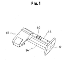
- a mould end cap is made from polyester resin and includes a cap end portion 12 having a large diameter and a mould insert portion 14 extending from the cap end portion 12.
- a leaf spring portion 16 extends in parallel with the mould insert portion 14 and a hook portion 10 protrudes convexly from a central portion of the leaf spring portion 16.
- An engagement part 18 substantially having a shape of letter "V" is formed across the ends of the mould insert portion 14 and the leaf spring portion 16 and extends in a direction perpendicular to the direction in which the mould insert portion 14 and the leaf spring portion 16 extend. Further, the mould insert portion 14 and the leaf spring portion 18 extend toward an opening end 22 of a mould body 20 as shown in FIG. 2.
- the direction from the mould end cap toward the opening end 22 of the mould body 20 is referred to as an "insertion direction.” Further, the insertion direction is referred to as “forward” (the front side), while its reverse direction is referred to as “backward” (the rear side).
- the hook portion 10 of the mould end cap has a first step portion 100 formed on the leaf spring portion 16, and a second portion 101 is formed on the first step portion 100.
- the first step portion 100 has a front surface 100a and a rear surface 100b, which are inclined and are opposite to each other.
- the front surface 100a and the rear surface 100b of the first step portion 100 may be inclined either at the same angle or at different angles.
- the first step portion 100 has a quadrangular column shape having a trapezoidal side surface 100c.
- the second step portion 101 on the first step portion 100 has an inclined front surface 101a, which is continuous to and in line with the front surface of 100a of the first step portion 100, so that the front surface 100a of the first step portion 100 and the front surface 101a of the second step portion 101 together compose a same single surface.
- the second step portion 101 has a vertical rear surface 101b connected to the rear surface 100b of the first step portion 100. Therefore, the second step portion 101 has a quadrangular column shape having a trapezoidal side surface 101c. Also, the second step portion 101 may have a quadrangular pyramid shape having a triangular side surface 101c.
- the upper surface 100d of the first step portion 100 is the same as the lower surface 101d of the second step portion 100.
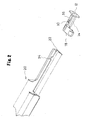
- the mould end cap configured as described above is inserted in the mould body 20 as shown in FIG. 2.
- the mould body 20 has an opening end 22 substantially having a shape of letter " ⁇ " into which the mould insert portion 14 of the mould end cap is inserted, and a notch portion 24 spaced a predetermined distance in the insertion direction of the mould insert portion 14 from the opening end 22.
- the mould insert portion 14 of the mould end cap is inserted in the opening end 22 of the mould body 20. Then, because the hook portion 10 includes the first step portion 100 and the second step portion 101, the mould insert portion 14 of the mould end cap can be inserted in the mould body 20 in an easy and smooth manner due to the front surfaces 100a and 101a of the first step portion 100 and the second step portion 101.
- the hook portion 10 is engaged with the notch portion 24.
- the engagement part 18 provided at the distal end of the mould end cap protrudes perpendicularly to the lengthwise direction of the mould body 20.
- the mould body 20 to which the mould end cap has been assembled may be attached as a part of a weather strip 32 to a door panel 30 of a vehicle frame as shown in FIG. 5.
- the engagement part 18 of the mould end cap is engaged with a portion inside of the door panel 30 of the vehicle frame, so as to prevent the mould body with the mould end cap from being separated from the door panel 30 of the vehicle frame.
- FIG. 1 because the engagement part 18 of the mould end cap is located adjacent to the hook portion 10, it is possible to reduce the entire length of the mould end cap and it is thus possible to reduce the manufacturing cost of the mould end cap.
- the engagement position between the notch portion 24 of the mould body 20 and the hook portion 10 of the mould end cap may have a small error according to the size or a positional deviation of the notch portion 24.
- the front end of the notch portion 24 is located at a position deviating backward from a predetermined position and the notch portion 24 has a size larger than a predetermined size. Then, the hook portion 10 is pushed outward by the elastic force of the leaf spring portion 16, so that the front surface 100a of the first step portion 100 or the front surface 101a of the second step portion 101 is engaged with the front end of the notch portion 24.
- the mould end cap has a hook portion 90 having a mountain-like shape as shown by a broken line in FIG. 6A, instead of the hook portion 10.
- the notch portion 24 has a size smaller than the predetermined size.
- the hook portion 10 is pushed outward in the way as described above, so that the front surface 100a and the rear surface 100b of the first step portion 100 or the front surface 101a and the rear surface 101b of the second step portion 101 are engaged with both ends of the notch portion 24.
- the mould end cap has a hook portion 90 having a mountain-like shape as shown by a broken line in FIG.
- a mould end cap according to an embodiment of the present invention can prevent generation of a gap between the mould end cap and the mould body 20 assembled with each other, and attain an intended design.
- a mould end cap according to an embodiment of the present invention can achieve the same effect as described above.
Landscapes
- Engineering & Computer Science (AREA)
- Mechanical Engineering (AREA)
- Vehicle Interior And Exterior Ornaments, Soundproofing, And Insulation (AREA)
- Braiding, Manufacturing Of Bobbin-Net Or Lace, And Manufacturing Of Nets By Knotting (AREA)
- Vehicle Step Arrangements And Article Storage (AREA)
Abstract
Description
- The present invention relates to a mould end cap to be attached to an end of a mould body.
- Conventional mould end caps are described in
Japanese Laid Open Utility Model No. 5-82694 Japanese Laid Open Patent No. 11-34757 - Cited reference 1 discloses a bonding film made from PVC resin, which is coated on an inner surface of the mould body to which the mould end cap is attached. The hook portion is bonded to the bonding film.
- Further, Cited reference 2 discloses a notch portion formed at the mould body, so that the hook portion of a mould end cap is engaged with the notch portion.
- Therefore, when the mould insert portion is inserted in the mould body, the hook portion may be bonded to the bonding film of the mould body or engaged with the notch portion, so that the mould end cap can be assembled with the mould body.
- However, in the conventional mould end cap disclosed in cited reference 1 as described above, the hook portion may sway due to the elasticity of the bonding film coated on the inner surface of the mould body. Further, in the conventional mould end cap disclosed in cited reference 2 as described above, because the notch portion is formed at the mould body, a secure engagement between the hook portion and the notch portion may be disturbed when any deviation in the location or size of the notch portion occurs. As a result, a gap may be generated between the end of the mould body and the mould end cap, thereby degrading a desirable appearance when the mould end cap has been assembled with the mould body.
- Accordingly, the present invention has been made to solve the above-mentioned limitations occurring in the related art. The present invention provides a mould end cap, which can prevent generation of a gap between the mould end cap and a mould body assembled with each other and attain an intended design.
- The present invention provides the configuration capable of automatically correcting error in positions of assembly between the mould end cap and the mould body.
- That is, in first aspect, the present invention provides a mould end cap as defined in claim 1 comprising: a cap end portion assembled with an end of a mould body for a vehicle frame; a mould insert portion extending from the cap end portion and inserted in the mould body; and a hook portion provided at the mould insert portion and engaged with the mould body, wherein the hook portion comprises: a first step portion having a quadrangular column shape, which has a front surface and a rear surface inclined and opposite to each other, and side surfaces each having a trapezoidal shape; and a second step portion located on an upper end of the first step portion, the second step portion having a quadrangular column or pyramid shape, which has an inclined front surface, a vertical rear surface, and side surfaces each having a trapezoidal or triangular shape.
- As used herein, the front surface of the first step portion and the second step portion refers to a surface oriented toward the mould body, and the rear surface of the first step portion and the second step portion refers to a surface oriented toward the cap end portion. The front surface and the rear surface of the first step portion may be inclined either at the same angle or different angles.
- Further, in second aspect of a mould end cap according to the present invention provides a mould end cap as defined in claim 2, the front surface of the first step portion and the second step portion compose a single continuous surface.
- The upper surface of the first step portion may be the same as the lower surface of the second step portion. Also, the side surfaces of the first step portion and the second step portion may compose a single continuous surface.
- Further, in third aspect of a mould end cap according to the present invention provides a mould end cap as defined in claim 3, the mould insert portion includes a leaf spring portion extending in an insertion direction toward the mould body, and the hook portion is formed at the leaf spring portion.
- Further, in forth aspect, the present invention provides a mould end cap as defined in claim 4 further comprising an engagement part extending in a direction perpendicular to the insertion direction toward the mould body and engaged with the vehicle frame, wherein the engagement part is located near the hook portion.
- The configuration in which the engagement part is located near the hook portion implies that the engagement part is located, for example, either before or behind the hook portion in the insertion direction toward the mould body.
- According to the first aspect of the present invention provides a mould end cap as defined in claim 1, the mould insert portion of the mould end cap can be easily inserted in the mould body for the vehicle frame, because the front surfaces of the first and second step portion in the hook portion form an inclined surface. Then, the front and rear surfaces of the first step portion and the front and rear surfaces of the second step portion in the hook portion are engaged with the notch portion, so that the mould end cap is assembled with the mould body. Even when a slight error occurs at the position at which the mould body and the mould end cap are assembled, at least one of the inclined front and rear surfaces of the first step portion and the inclined front surface and the vertical rear surface of the second step portion is engaged with the mould body without fail. By the engagement between at least one surface and the mould body as described above, it is possible to attach the mould end cap to the mould body at a portion between those surfaces and the cap end portion. Thus, it is possible to automatically correct an error that may occur at the position at which the mould body and the mould end cap are assembled. By such an automatic correction for the assembling position, it is possible to prevent a gap from being easily generated between the cap end portion of the mould end cap and the end portion of the mould body, thereby improving a desirable appearance in the state in which the mould end cap is assembled with the mould body.
- Therefore, the mould end cap according to the present invention can prevent generation of a gap between the mould end cap and the mould body assembled with each other, and attain an intended design.
- Further, according to a second aspect of the present invention provides a mould end cap as defined in claim 2, because the front surface of the first step portion and the front surface of the second step portion in the hook portion of the mould end cap compose a single continuous surface, the mould insert portion of the mould end cap can be easily inserted in the mould body.
- Further, according to a third aspect of the present invention provides a mould end cap as defined in claim 3, because the hook portion is formed at a leaf spring portion extending in an insertion direction toward the mould body, the hook portion can be pushed outward to the mould body by the elastic force of the leaf spring portion. By this, the hook portion of the mould end cap can be easily engaged with the mould body.
- Further, according to a forth aspect of the present invention provides a mould end cap as defined in claim 4, because the mould end cap further comprises an engagement part extending in a direction perpendicular to the insertion direction toward the mould body and engaged with the vehicle frame, it is possible to engage the mould body having the mould end cap attached thereto to the vehicle frame. Thus, it is possible to prevent the mould body with the mould end cap from being separated from the vehicle frame. Further, because the engagement part is located near the hook portion, it is possible to reduce the entire length of the mould end cap. As a result, it is possible to reduce the manufacturing cost of the mould end cap.
-
- FIG. 1 is a perspective view of a mould end cap according to an embodiment of the present invention;
- FIG. 2 is an exploded perspective view of a mould body and a mould end cap according to an embodiment of the present invention;
- FIG. 3 is an enlarged side view of a hook portion according to an embodiment of the present invention;
- FIG. 4 is a perspective view of a mould body and a mould end cap assembled with each other according to an embodiment of the present invention;
- FIG. 5 is a side view of a door panel of a vehicle frame according to an embodiment of the present invention; and
- FIGs. 6A to 6C are enlarged side views of a hook portion and a notch portion according to an embodiment of the present invention.
- Various embodiments of the present invention will now be described in detail with reference to the accompanying drawings.
- As shown in FIG. 1, a mould end cap according to an embodiment of the present invention is made from polyester resin and includes a
cap end portion 12 having a large diameter and amould insert portion 14 extending from thecap end portion 12. Aleaf spring portion 16 extends in parallel with themould insert portion 14 and ahook portion 10 protrudes convexly from a central portion of theleaf spring portion 16. Anengagement part 18 substantially having a shape of letter "V" is formed across the ends of themould insert portion 14 and theleaf spring portion 16 and extends in a direction perpendicular to the direction in which the mould insertportion 14 and theleaf spring portion 16 extend. Further, the mould insertportion 14 and theleaf spring portion 18 extend toward anopening end 22 of amould body 20 as shown in FIG. 2. As used herein, the direction from the mould end cap toward theopening end 22 of themould body 20 is referred to as an "insertion direction." Further, the insertion direction is referred to as "forward" (the front side), while its reverse direction is referred to as "backward" (the rear side). - Especially, as shown in FIG. 3, the
hook portion 10 of the mould end cap has afirst step portion 100 formed on theleaf spring portion 16, and asecond portion 101 is formed on thefirst step portion 100. Thefirst step portion 100 has afront surface 100a and arear surface 100b, which are inclined and are opposite to each other. Thefront surface 100a and therear surface 100b of thefirst step portion 100 may be inclined either at the same angle or at different angles. As a result, thefirst step portion 100 has a quadrangular column shape having atrapezoidal side surface 100c. Further, thesecond step portion 101 on thefirst step portion 100 has aninclined front surface 101a, which is continuous to and in line with the front surface of 100a of thefirst step portion 100, so that thefront surface 100a of thefirst step portion 100 and thefront surface 101a of thesecond step portion 101 together compose a same single surface. Further, thesecond step portion 101 has a verticalrear surface 101b connected to therear surface 100b of thefirst step portion 100. Therefore, thesecond step portion 101 has a quadrangular column shape having atrapezoidal side surface 101c. Also, thesecond step portion 101 may have a quadrangular pyramid shape having atriangular side surface 101c. Further, theupper surface 100d of thefirst step portion 100 is the same as thelower surface 101d of thesecond step portion 100. - The mould end cap configured as described above is inserted in the
mould body 20 as shown in FIG. 2. Themould body 20 has an openingend 22 substantially having a shape of letter "⊐" into which themould insert portion 14 of the mould end cap is inserted, and anotch portion 24 spaced a predetermined distance in the insertion direction of themould insert portion 14 from the openingend 22. - Therefore, as shown in FIG. 4, the
mould insert portion 14 of the mould end cap is inserted in the openingend 22 of themould body 20. Then, because thehook portion 10 includes thefirst step portion 100 and thesecond step portion 101, themould insert portion 14 of the mould end cap can be inserted in themould body 20 in an easy and smooth manner due to thefront surfaces first step portion 100 and thesecond step portion 101. - As the
mould insert portion 14 of the mould end cap is inserted in themould body 20, thehook portion 10 is engaged with thenotch portion 24. At this time, theengagement part 18 provided at the distal end of the mould end cap protrudes perpendicularly to the lengthwise direction of themould body 20. Themould body 20 to which the mould end cap has been assembled may be attached as a part of aweather strip 32 to adoor panel 30 of a vehicle frame as shown in FIG. 5. At this time, theengagement part 18 of the mould end cap is engaged with a portion inside of thedoor panel 30 of the vehicle frame, so as to prevent the mould body with the mould end cap from being separated from thedoor panel 30 of the vehicle frame. Further, as shown in FIG. 1, because theengagement part 18 of the mould end cap is located adjacent to thehook portion 10, it is possible to reduce the entire length of the mould end cap and it is thus possible to reduce the manufacturing cost of the mould end cap. - Herein, as shown in FIGs. 6A, 6B and 6C, the engagement position between the
notch portion 24 of themould body 20 and thehook portion 10 of the mould end cap may have a small error according to the size or a positional deviation of thenotch portion 24. Specifically, referring to FIG. 6A, the front end of thenotch portion 24 is located at a position deviating backward from a predetermined position and thenotch portion 24 has a size larger than a predetermined size. Then, thehook portion 10 is pushed outward by the elastic force of theleaf spring portion 16, so that thefront surface 100a of thefirst step portion 100 or thefront surface 101a of thesecond step portion 101 is engaged with the front end of thenotch portion 24. This engagement can be accomplished even when the mould end cap has ahook portion 90 having a mountain-like shape as shown by a broken line in FIG. 6A, instead of thehook portion 10. Further, in the case shown in FIG. 6B, thenotch portion 24 has a size smaller than the predetermined size. In this case also, thehook portion 10 is pushed outward in the way as described above, so that thefront surface 100a and therear surface 100b of thefirst step portion 100 or thefront surface 101a and therear surface 101b of thesecond step portion 101 are engaged with both ends of thenotch portion 24. However, when the mould end cap has ahook portion 90 having a mountain-like shape as shown by a broken line in FIG. 6B, instead of thehook portion 10, it is impossible to engage thehook portion 90 with thenotch portion 24. Further, in the case shown in FIG. 6C, the rear end of thenotch portion 24 is located at a position deviating forward from a predetermined position. In this case, thehook portion 10 is pushed outward in the way as described above, so that only therear surface 101b of thesecond step portion 101 is engaged with the rear end of thenotch portion 24. However, when the mould end cap has ahook portion 90 having a mountain-like shape as shown by a broken line in FIG. 6C, instead of thehook portion 10, it is impossible to engage thehook portion 90 with thenotch portion 24. As described above, when there is any deviation in the location or size of thenotch portion 24 of themould body 20, an error may occur in the position at which thehook portion 10 of the mould end cap is engaged with thenotch portion 24 of themould body 20. Even in this case, because of thefront surface rear surface first step portion 100 or thesecond step portion 101, thehook portion 10 can be engaged with thenotch portion 24 of themould body 20. Therefore, it is possible to attach the mould end cap to themould body 20 at a portion between those surfaces and thecap end portion 12. As a result, it is possible to automatically correct an error that may occur in the position at which thehook portion 10 of the mould end cap is engaged with thenotch portion 24 of themould body 20. Thus, it is possible to prevent a gap from easily generating between thecap end portion 12 of the mould end cap and the opening end of themould body 20, thereby providing a desirable appearance when the mould end cap has been assembled with themould body 20. - Therefore, a mould end cap according to an embodiment of the present invention can prevent generation of a gap between the mould end cap and the
mould body 20 assembled with each other, and attain an intended design. - Further, even when the
second step portion 101 has a quadrangular pyramidal shape, a mould end cap according to an embodiment of the present invention can achieve the same effect as described above.
Claims (4)
- A mould end cap comprising:a cap end portion engaged with an end of a mould body for a vehicle frame;a mould insert portion extending from the cap end portion and inserted in the mould body; anda hook portion provided at the mould insert portion and engaged with the mould body,wherein the hook portion comprises:a first step portion having a quadrangular column shape, which has a front surface and a rear surface inclined and opposite to each other, and side surfaces each having a trapezoidal shape; anda second step portion located on an upper end of the first step portion, the second step portion having a quadrangular column or pyramid shape, which has an inclined front surface, a vertical rear surface, and side surfaces each having a trapezoidal or triangular shape.
- The mould end cap as claimed in claim 1, wherein the front surface of the first step portion and the front surface of the second step portion compose a single continuous surface.
- The mould end cap as claimed in claim 1 or 2, wherein the mould insert portion includes a leaf spring portion extending in an insertion direction toward the mould body, and the hook portion is formed at the leaf spring portion.
- The mould end cap as claimed in any of claims 1 to 3, further comprising an engagement part extending in a direction perpendicular to the insertion direction toward the mould body and engaged with the vehicle frame, wherein the engagement part is located near the hook portion.
Applications Claiming Priority (1)
| Application Number | Priority Date | Filing Date | Title |
|---|---|---|---|
| PCT/JP2004/014974 WO2006038307A1 (en) | 2004-10-01 | 2004-10-01 | Lace end cap |
Publications (3)
| Publication Number | Publication Date |
|---|---|
| EP1795399A1 true EP1795399A1 (en) | 2007-06-13 |
| EP1795399A4 EP1795399A4 (en) | 2010-11-03 |
| EP1795399B1 EP1795399B1 (en) | 2011-09-28 |
Family
ID=36142397
Family Applications (1)
| Application Number | Title | Priority Date | Filing Date |
|---|---|---|---|
| EP04773708A Expired - Lifetime EP1795399B1 (en) | 2004-10-01 | 2004-10-01 | Mould end cap |
Country Status (4)
| Country | Link |
|---|---|
| US (1) | US7407205B2 (en) |
| EP (1) | EP1795399B1 (en) |
| CN (1) | CN100447021C (en) |
| WO (1) | WO2006038307A1 (en) |
Cited By (4)
| Publication number | Priority date | Publication date | Assignee | Title |
|---|---|---|---|---|
| GB2443319A (en) * | 2006-10-24 | 2008-04-30 | Nippon Pop Rivets And Fastners | Molding and end cap mounting structure |
| FR2943584A1 (en) * | 2009-03-24 | 2010-10-01 | Peugeot Citroen Automobiles Sa | Outer trim for front side door of motor vehicle, has interior surface comprising fixing unit for providing connection by co-operation of forms with complementary unit provided on part of door |
| FR2964348A1 (en) * | 2010-09-03 | 2012-03-09 | Peugeot Citroen Automobiles Sa | Device for fixing exterior window sealing strip on panel of door of e.g. motor vehicle, has rigid rod with portion whose eccentric form is blocked in support on extension of external skin of panel to exert effort on end part of strip |
| US8487044B2 (en) | 2009-11-25 | 2013-07-16 | Industrial Technology Research Institute | Oriented white polyester film |
Families Citing this family (20)
| Publication number | Priority date | Publication date | Assignee | Title |
|---|---|---|---|---|
| JP4272564B2 (en) * | 2004-03-10 | 2009-06-03 | シロキ工業株式会社 | Molding structure |
| US8001727B2 (en) * | 2007-07-24 | 2011-08-23 | Magna International Inc | Sealing molding with insert for forming closeout surface |
| JP5179284B2 (en) * | 2008-08-05 | 2013-04-10 | 片山工業株式会社 | Automotive mall |
| US20100313487A1 (en) * | 2009-06-16 | 2010-12-16 | Ellis Peter J | Applique with integrated end cap and window molding |
| KR101833202B1 (en) * | 2010-03-03 | 2018-03-02 | 쿠퍼-스탠다드 오토모티브 인코포레이티드 | Co-extruded roll formed bright extrusion with integral end forms |
| JP5355471B2 (en) * | 2010-03-30 | 2013-11-27 | シロキ工業株式会社 | End caps and moldings |
| DE102011014540A1 (en) * | 2011-03-19 | 2012-09-20 | Audi Ag | Profile seal with trim strip for a vehicle |
| MX2013011861A (en) * | 2011-04-13 | 2014-01-31 | Katayama Kogyo Co Ltd | Molding endcap. |
| US8572897B2 (en) * | 2011-09-14 | 2013-11-05 | Ford Global Technologies, Llc | Weatherstrip cinch clip |
| JP5909959B2 (en) * | 2011-09-26 | 2016-04-27 | アイシン精機株式会社 | Attaching the molding end cap |
| PL2692566T3 (en) | 2012-08-01 | 2019-03-29 | Henniges Automotive Sealing Systems North America, Inc. | Dual end cap for a seal assembly |
| EP3289573B1 (en) | 2015-04-30 | 2021-10-06 | Honeywell International Inc. | System for integrating multiple sensor data to predict a fall risk |
| KR20180044329A (en) | 2015-08-26 | 2018-05-02 | 쿠퍼-스탠다드 오토모티브 인코포레이티드 | End cap clip lock |
| JP6698368B2 (en) * | 2016-02-04 | 2020-05-27 | 西川ゴム工業株式会社 | Automotive door seal structure |
| DE102019116824A1 (en) * | 2019-06-21 | 2020-12-24 | Volkswagen Aktiengesellschaft | Sealing arrangement for a vehicle window, vehicle door and motor vehicle |
| JP7290334B2 (en) * | 2020-06-19 | 2023-06-13 | 片山工業株式会社 | Beltline molding and its terminal holding structure |
| CN112319394A (en) * | 2020-09-27 | 2021-02-05 | 宁波信泰机械有限公司 | Side wall trim structure |
| JP7406515B2 (en) * | 2021-02-04 | 2023-12-27 | 東海興業株式会社 | Belt molding and its manufacturing method |
| JP7605728B2 (en) | 2021-12-21 | 2024-12-24 | 東海興業株式会社 | Belt molding manufacturing method |
| US12403754B2 (en) | 2023-04-18 | 2025-09-02 | Rivian Ip Holdings, Llc | Hidden outer belt seal |
Family Cites Families (24)
| Publication number | Priority date | Publication date | Assignee | Title |
|---|---|---|---|---|
| US4066285A (en) * | 1976-12-09 | 1978-01-03 | Trim-Line, Inc. | Ornamental protective trim strip for motor vehicles |
| JPS5820437Y2 (en) * | 1979-05-28 | 1983-04-27 | 日産自動車株式会社 | Guard mold for automobiles |
| US4498697A (en) * | 1983-06-02 | 1985-02-12 | Mcglone William E | Portable, positionable, locking magnetic molding tubes for vehicle protection |
| US4617209A (en) * | 1985-01-08 | 1986-10-14 | Lof Plastics Inc. | Molded end cap for extruded trims |
| US4662671A (en) * | 1985-02-21 | 1987-05-05 | Carvalette Services Africa (Pty) Limited | Air deflector for motor vehicle |
| US4629232A (en) * | 1985-09-13 | 1986-12-16 | Chrysler Corporation | Spring mounted molding for a vehicle |
| US4726614A (en) * | 1986-08-25 | 1988-02-23 | Innovique Corporation | Vehicle body protector bumper |
| US4978490A (en) * | 1988-09-12 | 1990-12-18 | The Standard Products Company | Full overlaying injection molding |
| US4948637A (en) * | 1989-08-04 | 1990-08-14 | Gerald Kessler | Rub rail end caps |
| US4969674A (en) * | 1989-08-11 | 1990-11-13 | Wagner Scott J | Resilient vehicle side bumper |
| US5096753A (en) * | 1990-02-12 | 1992-03-17 | Mccue Corporation | Protective strip assembly |
| US5037148A (en) * | 1990-10-15 | 1991-08-06 | Alberto Kennedy | Body side guard |
| JPH04338525A (en) * | 1991-05-15 | 1992-11-25 | Tokai Kogyo Kk | Blow molded body and its manufacture |
| JPH0582694U (en) * | 1991-05-30 | 1993-11-09 | 株式会社東郷製作所 | End cap for mall |
| US6318045B1 (en) * | 1992-03-27 | 2001-11-20 | Ronald D. Kress | Clip for mounting molding |
| US5350608A (en) * | 1993-04-13 | 1994-09-27 | The Standard Products Company | Decorative trim with one-piece plastic cover |
| US5641547A (en) * | 1995-09-13 | 1997-06-24 | Plastic Trim, Inc. | Injection molded trim strip and method for making same |
| US5879037A (en) * | 1996-02-22 | 1999-03-09 | Batiste; Rene C. | Vehicle side panel dent preventer |
| JP3525692B2 (en) | 1997-07-23 | 2004-05-10 | 豊田合成株式会社 | Door belt molding outer for automobile |
| US6213186B1 (en) * | 1999-05-27 | 2001-04-10 | Irvin Automotive Products, Inc. | Unitary cassette assembly with integral package tray |
| JP4037191B2 (en) * | 2002-07-04 | 2008-01-23 | ポップリベット・ファスナー株式会社 | Clip for car door sash molding |
| JP4142464B2 (en) | 2003-02-18 | 2008-09-03 | シロキ工業株式会社 | Molding and manufacturing method thereof |
| US7210730B2 (en) * | 2004-02-26 | 2007-05-01 | Nishikawa Rubber Co., Ltd. | Mounting structure of automobile door |
| JP4235655B2 (en) * | 2006-04-27 | 2009-03-11 | アイシン精機株式会社 | Belt Mall |
-
2004
- 2004-10-01 WO PCT/JP2004/014974 patent/WO2006038307A1/en not_active Ceased
- 2004-10-01 CN CNB2004800441210A patent/CN100447021C/en not_active Expired - Fee Related
- 2004-10-01 EP EP04773708A patent/EP1795399B1/en not_active Expired - Lifetime
- 2004-10-01 US US11/662,382 patent/US7407205B2/en not_active Expired - Lifetime
Cited By (5)
| Publication number | Priority date | Publication date | Assignee | Title |
|---|---|---|---|---|
| GB2443319A (en) * | 2006-10-24 | 2008-04-30 | Nippon Pop Rivets And Fastners | Molding and end cap mounting structure |
| US7785686B2 (en) | 2006-10-24 | 2010-08-31 | Newfrey Llc | Molding |
| FR2943584A1 (en) * | 2009-03-24 | 2010-10-01 | Peugeot Citroen Automobiles Sa | Outer trim for front side door of motor vehicle, has interior surface comprising fixing unit for providing connection by co-operation of forms with complementary unit provided on part of door |
| US8487044B2 (en) | 2009-11-25 | 2013-07-16 | Industrial Technology Research Institute | Oriented white polyester film |
| FR2964348A1 (en) * | 2010-09-03 | 2012-03-09 | Peugeot Citroen Automobiles Sa | Device for fixing exterior window sealing strip on panel of door of e.g. motor vehicle, has rigid rod with portion whose eccentric form is blocked in support on extension of external skin of panel to exert effort on end part of strip |
Also Published As
| Publication number | Publication date |
|---|---|
| CN101031454A (en) | 2007-09-05 |
| CN100447021C (en) | 2008-12-31 |
| EP1795399A4 (en) | 2010-11-03 |
| US7407205B2 (en) | 2008-08-05 |
| EP1795399B1 (en) | 2011-09-28 |
| US20070278830A1 (en) | 2007-12-06 |
| WO2006038307A1 (en) | 2006-04-13 |
Similar Documents
| Publication | Publication Date | Title |
|---|---|---|
| EP1795399B1 (en) | Mould end cap | |
| US11162520B2 (en) | Dual material U-base fastener | |
| US6966601B2 (en) | Weather strip for a vehicle door | |
| US7188392B2 (en) | Spring fastener with highly improved lever/angle pulling force | |
| US7536755B2 (en) | Clip having engaging pawl portions and projecting portions | |
| US6718599B2 (en) | Spring fastener with ergonomically balanced removal to insertion force ratio | |
| US7018152B2 (en) | Clip | |
| US7640634B2 (en) | Ergonomic fastener | |
| EP1849643A3 (en) | Fuel flap for automobiles | |
| US20040083582A1 (en) | Fastener with ergonomic removal to insertion force ration | |
| JP2009012513A (en) | Weather Strip | |
| JP2004156722A (en) | Connector having male part for regular fixing | |
| US5597280A (en) | Locking clip with resilient barb arm | |
| US20140317889A1 (en) | Structure for attaching externally mounted member for vehicle | |
| US7219400B2 (en) | Clip and airbag body installation structure | |
| US20230220860A1 (en) | Fastener Clip Assembly with Locking Arms | |
| WO2012173248A1 (en) | Radiator grille clip, and vehicle attachment structure for radiator grille | |
| JP4292932B2 (en) | Mall end cap | |
| JP6851268B2 (en) | Automotive cover member and its mounting structure | |
| US20080315620A1 (en) | Auto Panel Attachment Device | |
| JP7060456B2 (en) | Automotive door weather strip | |
| US20050053425A1 (en) | Adjustable position retaining/mounting aperture | |
| US20030185644A1 (en) | Fastener for plastic structure | |
| JP3659902B2 (en) | Mall clips and malls with clips | |
| JP2019131092A (en) | Door weather strip for vehicle |
Legal Events
| Date | Code | Title | Description |
|---|---|---|---|
| PUAI | Public reference made under article 153(3) epc to a published international application that has entered the european phase |
Free format text: ORIGINAL CODE: 0009012 |
|
| 17P | Request for examination filed |
Effective date: 20070307 |
|
| AK | Designated contracting states |
Kind code of ref document: A1 Designated state(s): DE FR GB TR |
|
| DAX | Request for extension of the european patent (deleted) | ||
| RBV | Designated contracting states (corrected) |
Designated state(s): DE FR GB TR |
|
| A4 | Supplementary search report drawn up and despatched |
Effective date: 20101004 |
|
| 17Q | First examination report despatched |
Effective date: 20110204 |
|
| GRAP | Despatch of communication of intention to grant a patent |
Free format text: ORIGINAL CODE: EPIDOSNIGR1 |
|
| RIC1 | Information provided on ipc code assigned before grant |
Ipc: B60R 13/04 20060101AFI20110228BHEP |
|
| GRAS | Grant fee paid |
Free format text: ORIGINAL CODE: EPIDOSNIGR3 |
|
| GRAA | (expected) grant |
Free format text: ORIGINAL CODE: 0009210 |
|
| RTI1 | Title (correction) |
Free format text: MOULD END CAP |
|
| AK | Designated contracting states |
Kind code of ref document: B1 Designated state(s): DE FR GB TR |
|
| REG | Reference to a national code |
Ref country code: GB Ref legal event code: FG4D |
|
| REG | Reference to a national code |
Ref country code: DE Ref legal event code: R096 Ref document number: 602004034572 Country of ref document: DE Effective date: 20111201 |
|
| PLBE | No opposition filed within time limit |
Free format text: ORIGINAL CODE: 0009261 |
|
| STAA | Information on the status of an ep patent application or granted ep patent |
Free format text: STATUS: NO OPPOSITION FILED WITHIN TIME LIMIT |
|
| 26N | No opposition filed |
Effective date: 20120629 |
|
| REG | Reference to a national code |
Ref country code: DE Ref legal event code: R097 Ref document number: 602004034572 Country of ref document: DE Effective date: 20120629 |
|
| REG | Reference to a national code |
Ref country code: DE Ref legal event code: R084 Ref document number: 602004034572 Country of ref document: DE |
|
| REG | Reference to a national code |
Ref country code: DE Ref legal event code: R084 Ref document number: 602004034572 Country of ref document: DE Effective date: 20140904 |
|
| REG | Reference to a national code |
Ref country code: FR Ref legal event code: PLFP Year of fee payment: 13 |
|
| REG | Reference to a national code |
Ref country code: FR Ref legal event code: PLFP Year of fee payment: 14 |
|
| PGFP | Annual fee paid to national office [announced via postgrant information from national office to epo] |
Ref country code: TR Payment date: 20170921 Year of fee payment: 14 |
|
| REG | Reference to a national code |
Ref country code: FR Ref legal event code: PLFP Year of fee payment: 15 |
|
| PGFP | Annual fee paid to national office [announced via postgrant information from national office to epo] |
Ref country code: FR Payment date: 20190913 Year of fee payment: 16 |
|
| PGFP | Annual fee paid to national office [announced via postgrant information from national office to epo] |
Ref country code: GB Payment date: 20190926 Year of fee payment: 16 |
|
| PGFP | Annual fee paid to national office [announced via postgrant information from national office to epo] |
Ref country code: DE Payment date: 20190917 Year of fee payment: 16 |
|
| REG | Reference to a national code |
Ref country code: DE Ref legal event code: R119 Ref document number: 602004034572 Country of ref document: DE |
|
| GBPC | Gb: european patent ceased through non-payment of renewal fee |
Effective date: 20201001 |
|
| PG25 | Lapsed in a contracting state [announced via postgrant information from national office to epo] |
Ref country code: DE Free format text: LAPSE BECAUSE OF NON-PAYMENT OF DUE FEES Effective date: 20210501 Ref country code: FR Free format text: LAPSE BECAUSE OF NON-PAYMENT OF DUE FEES Effective date: 20201031 |
|
| PG25 | Lapsed in a contracting state [announced via postgrant information from national office to epo] |
Ref country code: GB Free format text: LAPSE BECAUSE OF NON-PAYMENT OF DUE FEES Effective date: 20201001 |
|
| PG25 | Lapsed in a contracting state [announced via postgrant information from national office to epo] |
Ref country code: TR Free format text: LAPSE BECAUSE OF NON-PAYMENT OF DUE FEES Effective date: 20201001 |