EP1795308A2 - Appareil à percussion - Google Patents
Appareil à percussion Download PDFInfo
- Publication number
- EP1795308A2 EP1795308A2 EP06124921A EP06124921A EP1795308A2 EP 1795308 A2 EP1795308 A2 EP 1795308A2 EP 06124921 A EP06124921 A EP 06124921A EP 06124921 A EP06124921 A EP 06124921A EP 1795308 A2 EP1795308 A2 EP 1795308A2
- Authority
- EP
- European Patent Office
- Prior art keywords
- damping element
- locking
- hammer
- tool holder
- striking device
- Prior art date
- Legal status (The legal status is an assumption and is not a legal conclusion. Google has not performed a legal analysis and makes no representation as to the accuracy of the status listed.)
- Withdrawn
Links
Images

Classifications
-
- B—PERFORMING OPERATIONS; TRANSPORTING
- B25—HAND TOOLS; PORTABLE POWER-DRIVEN TOOLS; MANIPULATORS
- B25D—PERCUSSIVE TOOLS
- B25D17/00—Details of, or accessories for, portable power-driven percussive tools
- B25D17/24—Damping the reaction force
-
- B—PERFORMING OPERATIONS; TRANSPORTING
- B25—HAND TOOLS; PORTABLE POWER-DRIVEN TOOLS; MANIPULATORS
- B25D—PERCUSSIVE TOOLS
- B25D2222/00—Materials of the tool or the workpiece
- B25D2222/54—Plastics
- B25D2222/57—Elastomers, e.g. rubber
Definitions
- the invention relates to a hammer blower, in particular an electro-pneumatic drill and / or chisel hammer, with a motor arranged in a housing, which drives an output element and a striking mechanism. Furthermore, the hammer blower on a tool holder on which an actable by the impact mechanism along an axis tool can be fixed and which can be fixed via a releasable locking mechanism on the output element.
- the locking mechanism has at least one locking body, via which a positive connection between a connecting part of the tool holder and the driven element can be produced in a locking position.
- the locking body can also be moved in the radial direction to the axis into an unlocking position, in which the positive locking is released, so that the tool holder can be removed from the driven element.
- an adjusting sleeve is provided, which supports the at least one locking body in the locking position against a radial displacement in a blocking position.
- the adjusting sleeve is adjustable in a working direction of the hammer-striking device against a spring force in a release position in which the locking body can be brought into the unlocking position.
- the tool holder can be removed in a particularly comfortable and tool-free manner of the driven element, for example, to replace it with a new or different tool holder.
- a hand tool machine which has a sleeve-shaped output element, in which an anvil is guided and on which a feed can be fixed.
- radially displaceable retaining elements are provided, via which an axial positive connection between a connecting part of the chuck and the driven element can be produced.
- the holding elements are in this case supported by an adjusting sleeve in the locking position, which is pressed counter to a working direction by a spring to a snap ring. To that To release food from the driven element, the adjusting sleeve is displaced in the working direction against a force of the spring, so that the holding elements are displaced radially outward and thereby cancel the positive connection between the connecting part and the output element.
- a disadvantage of the known device is that, during operation, in particular when empty beats, the striker strikes against an axial stop of the sleeve-shaped output element and a very large part of the impact energy is delivered via the connecting part and the snap ring held thereon to the adjusting sleeve. Often, in this case, the impact energy acting on the adjusting sleeve is sufficient to move it so far in the working direction that the retaining elements can be displaced into their unlocking position. This results in many cases an unintentional dropping of the feed from the hammer blower.
- the present invention has for its object to avoid the disadvantages mentioned in a hammer blower and to prevent unwanted loosening of the tool holder.
- the object is achieved in that in the attached state of the tool holder between the driven element and the connecting part, a damping element acting in the axial direction is provided.
- a damping element acting in the axial direction is provided in this way.
- the proportion of transmitted to the adjusting sleeve axially acting impact energy can be reduced so that even with empty blow of the striker on the connecting part of the tool holder, this can not give sufficient impulse to the adjusting sleeve to move it to the release position.
- the adjusting sleeve is unintentionally removed from the blocking position, which in turn the locking bodies are permanently supported in the locking position.
- the tool holder is securely held on the output element even in the case of clearances.
- a damping element receptacle for fixing the damping element is formed on the output element.
- the damping element receptacle is arranged on a side facing away from the impact mechanism side of an axial striker stop.
- the damping element can be securely supported against the working direction be without this additional recording elements would have to be provided. Rather, an already existing part is used as the axial limit of the damping element recording with the striker stop.
- the damping element has a radially protruding clamping element which is clamped in a terminal receiving the output element.
- the damping element can be completely determined in a particularly simple manner on the output element.
- the damping element in the unloaded state in the axial direction has a greater extent than an axial distance between a contact area of the connecting part and a support region facing the damping element receiving in the locked state of the tool holder.
- the damping element is axially biased in the locked state and pushes the tool holder away from the driven element.
- a good damping and on the other hand a particularly good definition of the tool holder relative to the driven element can be achieved.
- a required for the radial mobility of the locking body game is canceled.
- unnecessary noise and increased wear of the locking body or the elements that record this can be prevented as a result of the game.
- damping element is annular. As a result, the installation of the damping element is substantially facilitated.
- commercially available damping elements can be used in many cases, which reduces the manufacturing cost.
- the damping element is formed from an elastomer, whereby a sufficient degradation of the impact energy between the driven element and the tool holder and thus a sufficient reduction of the acceleration of the adjusting sleeve can be achieved in the working direction.
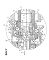
- Fig. 1 shows the front part of a hammer blower 2 in the form of a rotary hammer device, which has a motor 6 in a housing 4.
- the motor 6 is used as shown schematically for driving an exciter 8 of a percussion mechanism 10 and for rotary drive of an output element 12.
- the output element 12 is tubular and leads in a longitudinal bore 14 an anvil 16 of the impact mechanism 10, in turn of a through the exciter 8 driven bat 18 is acted upon.
- a tool holder 20 On the output member 12 is a tool holder 20, which serves to receive a tool 22 in the form of a drill or Meisselbits, via a releasable locking mechanism 24 can be fixed. In operation, this causes the tool holder 20 to rotate together with the driven element 12 about a common axis A. At the same time, the striking mechanism 10 acts on the tool 22 held on the tool holder 20 in a working direction R parallel to the axis A.
- the respective upper part relative to the axis A in FIGS. 1 and 2 shows the locking mechanism 24 in a locking position in which the tool holder 20 is locked to the driven element 12.
- the respective lower part in FIGS. 1 and 2 shows an unlocking position in which the tool holder 20 can be removed in the working direction R from the hammer-striking device 2, as indicated.
- the locking mechanism 24 on spherical locking body 26 which are held in radial bores 28 of a cup-shaped connecting part 30 of the tool holder 20 with respect to the axis A radially displaceable.
- this connection part 30 a free end 32 of the output element 12 is arranged.
- the displaceability of the locking body 26 is limited to the outside by an adjusting sleeve 34 with a recessed bearing ring 36.
- the adjusting sleeve 34 is biased by a spring force F of a spring 38 in a blocking position in which it bears against a snap ring 39 which is held on the connecting part 30.
- the locking bodies 26 are supported by the bearing ring 36 and protrude from an inner wall 40 of the connecting part 30.
- a positive connection between the output element 12 and the connecting part 30, whereby the tool holder 20 is fixed to the output member 12 via the locking body 26 is formed.
- the adjusting sleeve 34 can be moved by an operator, not shown, against the spring force F in the working direction R in a release position, which is shown in the lower part of Figs. 1 and 2.
- a recess 44 of the adjusting sleeve 34 is now arranged at the axial height of the radial bores 28. This allows the locking bodies 26 a radial movement to the outside until the locking body 26 are moved completely out of the locking receptacles 42 out.
- the positive connection of the connecting part 30 is lifted with the output member 12 via the locking body 26 and the tool holder 20 can, as shown, are removed in the working direction R of the output member 12 and thus from the hammer hammer 2.
- a circumferential striker stop 48 is fixedly connected to the output element 12, which limits the axial movement of the striker 16 in the working direction R.
- a support portion 50 which is arranged axially offset from an end face 52 of the driven element 12.
- the striker 48 and the output member 12 form an annular damping element receptacle 54, in which a likewise annular damping element 56 is held in elastomer.
- a radially outwardly directed rib-shaped clamping element 58 is formed on the damping element 56, which is pressed into a groove-shaped clamping receptacle 60 which is embedded in the inner surface 46 of the output element 12.
- This damping element 56 is located in the locking position, as can be seen from the upper half of Fig. 2, on a the output member 12 facing application area 62 of the connecting part 30 at.
- the damping element 56 as can be seen in particular from the lower half of Fig. 2 is an axial extent I, which is greater than an axial distance a between the application area 62 and the support portion 50 in the locked state of the tool holder 20, according to the upper part of Fig. 2.
- the damping element 56 is biased in producing the locking position according to the upper part of Fig. 2 and pushes the connecting member 30 away from the Output element 12.
Applications Claiming Priority (1)
| Application Number | Priority Date | Filing Date | Title |
|---|---|---|---|
| DE102005000179A DE102005000179A1 (de) | 2005-12-07 | 2005-12-07 | Hammerschlaggerät |
Publications (2)
| Publication Number | Publication Date |
|---|---|
| EP1795308A2 true EP1795308A2 (fr) | 2007-06-13 |
| EP1795308A3 EP1795308A3 (fr) | 2010-03-03 |
Family
ID=37771094
Family Applications (1)
| Application Number | Title | Priority Date | Filing Date |
|---|---|---|---|
| EP06124921A Withdrawn EP1795308A3 (fr) | 2005-12-07 | 2006-11-28 | Appareil à percussion |
Country Status (4)
| Country | Link |
|---|---|
| US (1) | US7357194B2 (fr) |
| EP (1) | EP1795308A3 (fr) |
| JP (1) | JP2007152550A (fr) |
| DE (1) | DE102005000179A1 (fr) |
Families Citing this family (5)
| Publication number | Priority date | Publication date | Assignee | Title |
|---|---|---|---|---|
| JP4898249B2 (ja) * | 2006-03-09 | 2012-03-14 | 株式会社マキタ | 作業工具 |
| DE102006000395A1 (de) * | 2006-08-07 | 2008-02-14 | Hilti Ag | Handwerkzeugmaschine mit pneumatischem Schlagwerk |
| CN203092484U (zh) * | 2013-02-22 | 2013-07-31 | 郭景辉 | 一种用于射钉枪的卸力装置 |
| JP7236921B2 (ja) * | 2019-04-18 | 2023-03-10 | 株式会社マキタ | 打撃工具 |
| US11826891B2 (en) * | 2019-10-21 | 2023-11-28 | Makita Corporation | Power tool having hammer mechanism |
Citations (3)
| Publication number | Priority date | Publication date | Assignee | Title |
|---|---|---|---|---|
| DE3443186A1 (de) * | 1984-11-27 | 1986-05-28 | Robert Bosch Gmbh, 7000 Stuttgart | Futter fuer handwerkzeugmaschinen, insbesondere bohr- und/oder schlaghaemmer |
| DE10005910A1 (de) * | 2000-02-10 | 2001-08-23 | Bosch Gmbh Robert | Handwerkzeugmaschine |
| WO2002024403A1 (fr) * | 2000-09-22 | 2002-03-28 | Robert Bosch Gmbh | Machine-outil a main pourvue d'un porte-outil amovible |
Family Cites Families (16)
| Publication number | Priority date | Publication date | Assignee | Title |
|---|---|---|---|---|
| US3168324A (en) * | 1963-02-15 | 1965-02-02 | Ingersoll Rand Co | Chuck |
| US3559753A (en) * | 1969-05-21 | 1971-02-02 | Ilmar Meri | Percussion tool |
| SU1662832A1 (ru) * | 1988-09-23 | 1991-07-15 | Московское Научно-Производственное Объединение По Механизированному Строительному Инструменту И Отделочным Машинам | Машина ударного действи |
| DE3924620A1 (de) * | 1989-07-26 | 1991-01-31 | Hilti Ag | Pulverkraftbetriebenes bolzensetzgeraet |
| US5325929A (en) * | 1991-07-09 | 1994-07-05 | Bretec Oy | Hydraulic impact hammer |
| SE469970B (sv) * | 1992-06-15 | 1993-10-18 | Uniroc Grinding Ab | Vibrationsdämpande slipkopp för slipning av hårdmetallstift hos stiftborrkronor och hållare för en sådan slipkopp |
| DE19604282A1 (de) * | 1996-02-07 | 1997-08-14 | Bosch Gmbh Robert | Werkzeughalter mit Aufnahme für verschiedene Werkzeugsysteme |
| DE19638341A1 (de) * | 1996-09-19 | 1998-03-26 | Wuerth Adolf Gmbh & Co Kg | Bolzenschubgerät und Feder dafür |
| KR200207572Y1 (ko) * | 1998-12-04 | 2001-01-15 | 이원해 | 유압식 착암기의 방음 방진 장치 |
| GB9910599D0 (en) * | 1999-05-08 | 1999-07-07 | Black & Decker Inc | Rotary hammer |
| DE19933972A1 (de) * | 1999-07-20 | 2001-01-25 | Bosch Gmbh Robert | Bohr- oder Schlaghammer |
| US6510904B1 (en) * | 2000-05-26 | 2003-01-28 | Nippon Pneumatic Mfg. Co., Ltd. | Protected tool bushing for an impact hammer |
| US6705409B2 (en) * | 2001-03-22 | 2004-03-16 | Chicago Pneumatic Tool Company | Reciprocating tool having a piston retaining system |
| WO2003024671A2 (fr) * | 2001-09-17 | 2003-03-27 | Milwaukee Electric Tool Corporation | Marteau rotatif |
| GB2401570B (en) * | 2003-05-12 | 2006-07-05 | Black & Decker Inc | Spindle assembly for hammer drill |
| US7131563B2 (en) * | 2005-01-28 | 2006-11-07 | De Poan Pneumatic Corp. | Nail driver bumper |
-
2005
- 2005-12-07 DE DE102005000179A patent/DE102005000179A1/de not_active Ceased
-
2006
- 2006-11-28 EP EP06124921A patent/EP1795308A3/fr not_active Withdrawn
- 2006-12-05 JP JP2006328027A patent/JP2007152550A/ja not_active Withdrawn
- 2006-12-06 US US11/635,263 patent/US7357194B2/en not_active Expired - Fee Related
Patent Citations (3)
| Publication number | Priority date | Publication date | Assignee | Title |
|---|---|---|---|---|
| DE3443186A1 (de) * | 1984-11-27 | 1986-05-28 | Robert Bosch Gmbh, 7000 Stuttgart | Futter fuer handwerkzeugmaschinen, insbesondere bohr- und/oder schlaghaemmer |
| DE10005910A1 (de) * | 2000-02-10 | 2001-08-23 | Bosch Gmbh Robert | Handwerkzeugmaschine |
| WO2002024403A1 (fr) * | 2000-09-22 | 2002-03-28 | Robert Bosch Gmbh | Machine-outil a main pourvue d'un porte-outil amovible |
Also Published As
| Publication number | Publication date |
|---|---|
| EP1795308A3 (fr) | 2010-03-03 |
| US7357194B2 (en) | 2008-04-15 |
| JP2007152550A (ja) | 2007-06-21 |
| US20070125564A1 (en) | 2007-06-07 |
| DE102005000179A1 (de) | 2007-06-14 |
Similar Documents
| Publication | Publication Date | Title |
|---|---|---|
| EP1882559B1 (fr) | Outil à main doté d'un dispositif de découplage | |
| EP1716979B1 (fr) | Marteau perforateur ou marteau-burineur | |
| EP0888851B1 (fr) | Appareil de forage - et/ou de percussion | |
| EP1326736B1 (fr) | Porte-outil pour une machine-outil | |
| EP1800803B1 (fr) | Outil manuel avec un mécanisme de percussion à rochet | |
| EP0733443B1 (fr) | Dispositif pour transmettre des coups par impulsion sur un outil à rotation continue | |
| EP0494400A2 (fr) | Outil à main avec porte-outil détachable | |
| DE10241054A1 (de) | Werkzeug und Werkzeughalter für eine Handwerkzeugmaschine | |
| CH655892A5 (de) | Bohrhammer mit fuehrungszylinder fuer das schlagwerk. | |
| DE3422195A1 (de) | Schlagbohreinrichtung | |
| EP0548008B1 (fr) | Outil pour forage à percussion et ciselage et mandrin pour cet outil | |
| EP1795308A2 (fr) | Appareil à percussion | |
| EP2116333A1 (fr) | Perceuse à percussion | |
| DE3828309C2 (fr) | ||
| EP0266305B1 (fr) | Marteau de forage avec mécanisme de percussion | |
| EP0155402B1 (fr) | Perforatrice à percussion | |
| DE4441820B4 (de) | Bohr- und/oder Schlaghammer | |
| DE4343583B4 (de) | Bohrhammer | |
| EP0152645B1 (fr) | Sélecteur de dispositif de forage à percussion ou rotation avec protection du mandrin | |
| EP1877227B1 (fr) | Outil d'insertion et porte-outil pour une machine outil a main | |
| WO2017032642A1 (fr) | Outil de pose | |
| DE3133085A1 (de) | Spannfutter, insbesondere fuer schlagbohrwerkzeuge | |
| DE69918532T2 (de) | Schlagbohrmaschine | |
| EP1293289B1 (fr) | Porte-outil interchangeable | |
| DE102011082080A1 (de) | Werkzeughalter für eine Handwerkzeugmaschine |
Legal Events
| Date | Code | Title | Description |
|---|---|---|---|
| PUAI | Public reference made under article 153(3) epc to a published international application that has entered the european phase |
Free format text: ORIGINAL CODE: 0009012 |
|
| AK | Designated contracting states |
Kind code of ref document: A2 Designated state(s): AT BE BG CH CY CZ DE DK EE ES FI FR GB GR HU IE IS IT LI LT LU LV MC NL PL PT RO SE SI SK TR |
|
| AX | Request for extension of the european patent |
Extension state: AL BA HR MK YU |
|
| PUAL | Search report despatched |
Free format text: ORIGINAL CODE: 0009013 |
|
| AK | Designated contracting states |
Kind code of ref document: A3 Designated state(s): AT BE BG CH CY CZ DE DK EE ES FI FR GB GR HU IE IS IT LI LT LU LV MC NL PL PT RO SE SI SK TR |
|
| AX | Request for extension of the european patent |
Extension state: AL BA HR MK RS |
|
| 17P | Request for examination filed |
Effective date: 20100903 |
|
| 17Q | First examination report despatched |
Effective date: 20101005 |
|
| AKX | Designation fees paid |
Designated state(s): CH DE ES FR GB IT LI |
|
| STAA | Information on the status of an ep patent application or granted ep patent |
Free format text: STATUS: THE APPLICATION IS DEEMED TO BE WITHDRAWN |
|
| 18D | Application deemed to be withdrawn |
Effective date: 20110416 |