EP1794402B1 - Invisible division bar modular assembly - Google Patents
Invisible division bar modular assembly Download PDFInfo
- Publication number
- EP1794402B1 EP1794402B1 EP05791162A EP05791162A EP1794402B1 EP 1794402 B1 EP1794402 B1 EP 1794402B1 EP 05791162 A EP05791162 A EP 05791162A EP 05791162 A EP05791162 A EP 05791162A EP 1794402 B1 EP1794402 B1 EP 1794402B1
- Authority
- EP
- European Patent Office
- Prior art keywords
- division bar
- window
- bar assembly
- leg
- support
- Prior art date
- Legal status (The legal status is an assumption and is not a legal conclusion. Google has not performed a legal analysis and makes no representation as to the accuracy of the status listed.)
- Ceased
Links
- 235000021189 garnishes Nutrition 0.000 claims description 10
- 239000013536 elastomeric material Substances 0.000 claims description 9
- 239000002783 friction material Substances 0.000 claims description 9
- 238000007789 sealing Methods 0.000 claims description 7
- 244000144992 flock Species 0.000 claims description 2
- 238000000465 moulding Methods 0.000 abstract description 27
- 239000011521 glass Substances 0.000 abstract description 23
- 238000005538 encapsulation Methods 0.000 abstract description 13
- 210000001503 joint Anatomy 0.000 abstract description 2
- 239000000463 material Substances 0.000 description 6
- 230000008901 benefit Effects 0.000 description 5
- 229920001971 elastomer Polymers 0.000 description 5
- 239000004033 plastic Substances 0.000 description 4
- 229920003023 plastic Polymers 0.000 description 4
- 229920000915 polyvinyl chloride Polymers 0.000 description 3
- 239000004800 polyvinyl chloride Substances 0.000 description 3
- 229920006342 thermoplastic vulcanizate Polymers 0.000 description 3
- 229920002943 EPDM rubber Polymers 0.000 description 2
- 230000000712 assembly Effects 0.000 description 2
- 238000000429 assembly Methods 0.000 description 2
- 239000004743 Polypropylene Substances 0.000 description 1
- 208000003443 Unconsciousness Diseases 0.000 description 1
- 230000004075 alteration Effects 0.000 description 1
- 230000009286 beneficial effect Effects 0.000 description 1
- 239000000806 elastomer Substances 0.000 description 1
- 239000008393 encapsulating agent Substances 0.000 description 1
- 230000006872 improvement Effects 0.000 description 1
- 238000010348 incorporation Methods 0.000 description 1
- 230000014759 maintenance of location Effects 0.000 description 1
- 230000000873 masking effect Effects 0.000 description 1
- 239000002184 metal Substances 0.000 description 1
- 238000000034 method Methods 0.000 description 1
- 239000000203 mixture Substances 0.000 description 1
- 238000012986 modification Methods 0.000 description 1
- 230000004048 modification Effects 0.000 description 1
- -1 polypropylene Polymers 0.000 description 1
- 229920001155 polypropylene Polymers 0.000 description 1
- 230000008569 process Effects 0.000 description 1
- 229920001169 thermoplastic Polymers 0.000 description 1
- 239000004416 thermosoftening plastic Substances 0.000 description 1
- 230000007704 transition Effects 0.000 description 1
Images


Classifications
-
- B—PERFORMING OPERATIONS; TRANSPORTING
- B60—VEHICLES IN GENERAL
- B60J—WINDOWS, WINDSCREENS, NON-FIXED ROOFS, DOORS, OR SIMILAR DEVICES FOR VEHICLES; REMOVABLE EXTERNAL PROTECTIVE COVERINGS SPECIALLY ADAPTED FOR VEHICLES
- B60J1/00—Windows; Windscreens; Accessories therefor
- B60J1/08—Windows; Windscreens; Accessories therefor arranged at vehicle sides
-
- B—PERFORMING OPERATIONS; TRANSPORTING
- B60—VEHICLES IN GENERAL
- B60J—WINDOWS, WINDSCREENS, NON-FIXED ROOFS, DOORS, OR SIMILAR DEVICES FOR VEHICLES; REMOVABLE EXTERNAL PROTECTIVE COVERINGS SPECIALLY ADAPTED FOR VEHICLES
- B60J10/00—Sealing arrangements
-
- B—PERFORMING OPERATIONS; TRANSPORTING
- B60—VEHICLES IN GENERAL
- B60J—WINDOWS, WINDSCREENS, NON-FIXED ROOFS, DOORS, OR SIMILAR DEVICES FOR VEHICLES; REMOVABLE EXTERNAL PROTECTIVE COVERINGS SPECIALLY ADAPTED FOR VEHICLES
- B60J10/00—Sealing arrangements
- B60J10/20—Sealing arrangements characterised by the shape
- B60J10/26—Sealing arrangements characterised by the shape characterised by the surface shape
-
- B—PERFORMING OPERATIONS; TRANSPORTING
- B60—VEHICLES IN GENERAL
- B60J—WINDOWS, WINDSCREENS, NON-FIXED ROOFS, DOORS, OR SIMILAR DEVICES FOR VEHICLES; REMOVABLE EXTERNAL PROTECTIVE COVERINGS SPECIALLY ADAPTED FOR VEHICLES
- B60J10/00—Sealing arrangements
- B60J10/30—Sealing arrangements characterised by the fastening means
-
- B—PERFORMING OPERATIONS; TRANSPORTING
- B60—VEHICLES IN GENERAL
- B60J—WINDOWS, WINDSCREENS, NON-FIXED ROOFS, DOORS, OR SIMILAR DEVICES FOR VEHICLES; REMOVABLE EXTERNAL PROTECTIVE COVERINGS SPECIALLY ADAPTED FOR VEHICLES
- B60J10/00—Sealing arrangements
- B60J10/50—Sealing arrangements characterised by means for prevention or reduction of noise, e.g. of rattling or vibration of windows
-
- B—PERFORMING OPERATIONS; TRANSPORTING
- B60—VEHICLES IN GENERAL
- B60J—WINDOWS, WINDSCREENS, NON-FIXED ROOFS, DOORS, OR SIMILAR DEVICES FOR VEHICLES; REMOVABLE EXTERNAL PROTECTIVE COVERINGS SPECIALLY ADAPTED FOR VEHICLES
- B60J10/00—Sealing arrangements
- B60J10/70—Sealing arrangements specially adapted for windows or windscreens
- B60J10/74—Sealing arrangements specially adapted for windows or windscreens for sliding window panes, e.g. sash guides
- B60J10/78—Sealing arrangements specially adapted for windows or windscreens for sliding window panes, e.g. sash guides adjacent to corner pieces, mirror supports or quarter windows
-
- E—FIXED CONSTRUCTIONS
- E06—DOORS, WINDOWS, SHUTTERS, OR ROLLER BLINDS IN GENERAL; LADDERS
- E06B—FIXED OR MOVABLE CLOSURES FOR OPENINGS IN BUILDINGS, VEHICLES, FENCES OR LIKE ENCLOSURES IN GENERAL, e.g. DOORS, WINDOWS, BLINDS, GATES
- E06B7/00—Special arrangements or measures in connection with doors or windows
- E06B7/16—Sealing arrangements on wings or parts co-operating with the wings
Definitions
- the present invention relates generally to a division bar modular assembly, according to the preamble of claim 1, that interfaces between a fixed window and a movable window of a vehicle.
- a division bar modular assembly according to the preamble of claim 1, that interfaces between a fixed window and a movable window of a vehicle.
- Such an assembly is known from US 4874201 A .
- An improvement of the modular molding assembly that adequately seals about the windows of a vehicle, addresses assembly issues, and provides a division bar assembly with a smooth and flush appearance and that improves wind noise is desired.
- An invisible division bar is provided that spans the interface between a movable widow and a fixed window, and guides and seals the movable window while providing a flush glass appearance, i.e., without protruding beyond an exterior surface of the windows.
- a preferred embodiment of the division bar assembly includes a first portion or support secured to a fixed window and a second portion or guide fixed to the movable window.
- the guide is received in a guide member cavity of the support which includes a low-friction material.
- At least one seal lip extends from the support for engaging an inner surface of the movable window.
- An inner garnish assembly is provided in a preferred arrangement to provide an aesthetic cover along the interior surface of the vehicle.
- the support preferably includes a cavity that receives a glass run channel.
- the glass run channel in a preferred arrangement includes the low friction material.
- the division bar assembly does not have any portion extending onto the external surfaces of the windows.
- a primary benefit of the invention is the improved aesthetics associated with the arrangement.
- Another benefit offered by the invention is the low profile and reduced wind noise associated therewith.
- Still another benefit is the ease of incorporation of the assembly into a surround molding module that facilitates assembly.
- FIGURE 1 is an elevational view of a prior art molding module used in association with a movable window and a fixed window.
- FIGURE 2 is a sectional view taken generally along the lines 2-2 in FIGURE 1 .
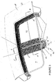
- FIGURE 3 is a representation, partly in section, of a preferred embodiment of the present invention.
- FIGURE 4 is a cross-sectional view taken generally along the lines 4-4 of FIGURE 3 .
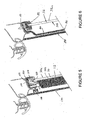
- FIGURE 5 is a sectional view taken generally along the lines 5-5 though the movable window portion of FIGURE 3 .
- FIGURE 6 is a sectional view taken generally along the lines 6-6 through the fixed window portion of FIGURE 3 .
- FIGURES 1 and 2 a prior art arrangement disclosed in U.S. Patent No. 5,702,148 commonly owned by the assignee of the present application, is shown. More particularly, the prior art arrangement shows a molding module 20 that comprises a one-piece surround molding 22, a glass run channel 24, a belt line outer seal 26, and a divider or division bar 28. The division bar is interposed between a movable window 30 and a fixed window 32 ( FIGURE 2 ).
- the one-piece surround molding includes a belt line portion 34, a B-pillar 36, top or header portion 38, and a sloping rear portion 40. Attachment flange portions and a series of attachment clips 42 provide for support and retention of the module or surround molding to the vehicle.
- the prior art division bar assembly 28 includes first and second legs 50, 52 that are in generally parallel relation and form a cavity 54 that receives the glass run channel 24.
- the glass run channel includes a pair of legs having seal lips 56, 58 that engage a first or outer surface 30a and a second or inner surface 30b, respectively, of the movable window 30.
- the glass run channel 24 typically incorporates a low-friction material such as flock 60 along the seal lips and in a base 62 of the glass run channel to provide a sliding, low friction engagement with the movable window.
- the conventional division bar assembly 28 further includes a molded elastomeric material 70 that encapsulates a perimeter edge of the fixed window 32. More particularly, the elastomeric window encapsulation 70 engages opposite first or exterior surface 32a and a second or interior surface 32b of the fixed window 32.
- the window encapsulation is preferably formed in an insert molding process where the elastomeric material is bonded to the first and second legs 50, 52 and forms a seal against the outside elements.
- a leg 72 of the surround molding 22 is received in a recess 74 between the division bar and the elastomer material to provide an aesthetic cover in the division bar region of the vehicle.
- the division bar Although this surround molding module has met with commercial success, the division bar unfortunately provides a raised surface at the interface between the movable and fixed windows, i.e., a raised division bar that is unsightly, and also contributes to wind noise because of the extent by which the division bar protrudes from the external surface of the windows.
- FIGURES 3 and 4 more particularly illustrate the subject invention which relates to what is termed herein as an invisible division bar assembly 80.
- the invisible division bar spans the interface between the movable window 30 and fixed window 32.
- the window encapsulation 82 preferably an elastomeric material molded to the fixed window, extends about the entire perimeter of the fixed window.
- the elastomeric encapsulation 82 engages not only the interior surface 32b of the fixed window and the outer edge 32c, but also extends over an outer extent of the exterior surface 32a of the fixed window.
- this portion of the elastomeric encapsulation at the invisible division bar region is also referred to as a support 84.
- the support spans generally vertically between the header and belt line and in a preferred arrangement includes a rigid support member 86, such as a metal or plastic support member, substantially encapsulated in the elastomeric material.
- the support member 86 includes a first leg 86a that extends generally parallel to the interior surface of the fixed window (and which may include one face that is not encapsulated in the elastomeric material), a second leg 86b extending generally perpendicularly toward the interior of the vehicle, and a third leg 86c that extends forwardly from the second leg and in generally parallel, spaced relation from the interior surface of the movable window ( FIGURE 4 ).
- the elastomeric material of the support 84 may be formed from a wide range of suitable materials such as molded rubber, TPV (thermoplastic vulcanizate), PVC (polyvinyl chloride), or thermoplastic, that is adhesively secured, molded, or rubber bonded to the interior surface 32b and outer edge 32c of the fixed window.
- TPV thermoplastic vulcanizate
- PVC polyvinyl chloride
- thermoplastic thermoplastic bonded to the interior surface 32b and outer edge 32c of the fixed window.
- this portion of the window encapsulation or support provides a butt joint between the movable and fixed windows and does not extend outwardly beyond the plane defined by the exterior surface of the movable and fixed windows. No portion of the support is received over the exterior surface 32a of the fixed window nor extends beyond the plane of the exterior surface of the window. This flush arrangement enhances the aesthetics of the division bar assembly and reduces issues with respect to wind noise.
- the surround molding portion includes a first portion or leg 92 secured to the support, shown here as extending parallel to and preferably secured by fasteners 94, to the second leg 86b of the support. It will be appreciated, however, that other securing arrangements may be used without departing from the scope and intent of the present invention.
- Second and third portions 96, 98 of the surround molding are disposed in spaced, generally parallel relation and define a recess or cavity 100, shown here as a pair of spaced legs extending generally parallel to the interior surface of the movable window.
- the second and third legs 96, 98 defining the recess 100 form a guide member adapted to receive a leg 110 of guide or window encapsulation 112 that is secured to the interior surface of the movable window adjacent the vertical rear edge thereof.
- the widow encapsulant of the movable window can be any suitable material such as a molded rubber, EPDM, TPV, PVC, etc., that is secured to the interior surface of the movable window, for example, adhesively secured thereto.
- the window encapsulation 112 can also be molded or rubber bonded to the movable window.
- the leg 110 is dimensioned for receipt in the cavity 100 and serves the function of guiding or tracking the rear vertical edge of the movable window.
- a low friction material is provided in the cavity shown here as a generally U-shaped insert 114 interposed between the legs 96, 98 and the guide leg 110.
- Generally parallel legs 114a, 114b of the low friction material insert may be slightly bowed or curved into engagement with the guide leg 110. This arrangement provides a desired low-friction, sliding engagement for the tracking of the rear vertical edge of the movable window.
- a glass run channel 116 that includes at least one and preferably a pair of sealing guide lips 118.
- the sealing guide lips are either formed of a low-friction material, or include a low-friction material along selected portions thereof to provide the desired low-friction, sliding sealing engagement with the interior surface of the movable window.
- the glass run channel is formed so that a first edge 120 defines a hook-shape or channel received over the leg 96 of the molding.
- a leg 122 is received in a recess formed between the first leg and the remainder of the surround molding body 90 and is contoured to provide a snap-fit connection with the molding body. This effectively secures the glass run channel 116 to the support which is, in turn, secured to the fixed window.
- the guide leg 110 received in the recess 100, an effective window seal and support is provided along the rear, vertical edge of the movable window.
- an inner garnish 130 is provided as a part of the invisible division bar assembly 80.
- the garnish 130 is a fully molded surround component that is mechanically secured to the invisible division bar assembly, as well as to the remainder of the surround molding.
- one preferred material is a plastic such as a polypropylene, although the invention should not be limited to this particular type of material.
- the inner garnish is also shown as being mechanically fastened to the support along the invisible division bar assembly, while along other regions of the surround molding module, the inner garnish may include a leg secured by clips (see left- and right-hand cross sections along the invisible division bar assembly).
- the inner garnish has overlay or cover portions 134; 136 that provide an aesthetic finish to the assembly so that the individual components of the division bar assembly are visible from the interior of the vehicle.
- the surround molding 90 is preferably either molded, extruded, or formed separately from the other components, while the glass run channel 116 in the preferred arrangement is molded at the upper B-pillar and molded in the division bar to the header.
- Preferred materials are EPDM or plastic, although plastic has the additional advantage of reduced cost.
- the front vertical edge of the fixed window 32 and the rear vertical edge of the movable window 30 are darkened, for example with a black-out frit 140.
- the frit is provided for aesthetic reasons of masking or hiding the remaining components of the invisible division bar assembly.
- FIGURE 5 illustrates a cross-section through the header portion adjacent the movable window.
- the surround molding 150 in this region includes a pair of spaced legs 152, 154 forming a channel 156 that receives a generally conventional glass run channel 160.
- the glass run channel legs include seal lips 162, 164 which engage the inner and outer surfaces of the movable window.
- the surround molding module further includes leg 166 that secures the inner trim 170. It is also apparent from FIGURE 5 that the guide or window encapsulation 112 secured to the interior surface 30b of the movable window also terminates before reaching the upper edge of the movable window. This allows that portion of the movable window to be effectively received in the glass run channel along the header.
- FIGURE 6 illustrates a cross-sectional view along the header portion, but through the fixed window region. This view further illustrates how the support assembly 84 of the invisible division bar assembly is secured to the vehicle body, for example via fasteners 150, and moreover how the inner trim 170 effectively covers the invisible division bar assembly in this region, as well as covering the interfit between the surround molding and the window encapsulation of the fixed window.
- the door seal assembly is secured to flanges of the vehicle body and has hollow bulb portions that extend into sealing engagement with portions of the door.
Landscapes
- Engineering & Computer Science (AREA)
- Mechanical Engineering (AREA)
- Civil Engineering (AREA)
- Structural Engineering (AREA)
- Seal Device For Vehicle (AREA)
- Window Of Vehicle (AREA)
- Vehicle Interior And Exterior Ornaments, Soundproofing, And Insulation (AREA)
- Fittings On The Vehicle Exterior For Carrying Loads, And Devices For Holding Or Mounting Articles (AREA)
- Coupling Device And Connection With Printed Circuit (AREA)
Abstract
Description
- The present invention relates generally to a division bar modular assembly, according to the preamble of claim 1, that interfaces between a fixed window and a movable window of a vehicle. Such an assembly is known from
US 4874201 A . - It is known to provide a division bar that extends in a generally vertical direction between header and belt line portions of a vehicle window opening. The division bar is typically attached to or molded into a window encapsulation assembly associated with the fixed window. Unfortunately, known arrangements do not adequately address wind noise, aesthetics or appearance, and are not integrally incorporated into a glass guide tracking system for the adjacent movable window. It would therefore be desirable to provide a flush appearance with no glass offset, and particularly one incorporated into a surround module that adequately seals against the movable window. It would also be beneficial if the window provided a flush appearance with the division bar. Aesthetically, it would create a smoother line that provides a generally continuous glass-look finish between the front and movable window and a rear or fixed window. Moreover, known division bar assemblies extend outwardly from an exterior surface or plane of the windows. Aside from the aesthetic appearance issues noted above, the outwardly extending division bar creates an undesired drag and generates wind noise.
- Conventional sealing systems often incorporate multiple components for sealing about the periphery of the window to the vehicle. In addition, these assemblies must provide a smooth transition with the vehicle body, i.e., blend in and provide an aesthetically pleasing appearance with the exterior vehicle appearance. Thus, moldings are provided with the glass run channels to improve the exterior appearance of the glass run channel. Likewise, a separate or inner garnish trim is usually provided to add a pleasing appearance about the window opening along the interior of the vehicle. Again, multiple assembly operations are typically required to Secure the glass run channel, belt weatherstrip, decorative molding, inner garnish, etc. Each component adds additional cost and assembly. Thus, it has been proposed by the assignee of the present application to provide a surround molding module such as shown and described in
U.S. Patent No. 5,702,148 . As described in the '148 patent, a fixed glass assembly typically incorporates a divider bar, one portion of which supports the glass run channel and a second portion formed of an elastomeric material molded about the periphery of the fixed window. - An improvement of the modular molding assembly that adequately seals about the windows of a vehicle, addresses assembly issues, and provides a division bar assembly with a smooth and flush appearance and that improves wind noise is desired.
- An invisible division bar is provided that spans the interface between a movable widow and a fixed window, and guides and seals the movable window while providing a flush glass appearance, i.e., without protruding beyond an exterior surface of the windows.
- A preferred embodiment of the division bar assembly includes a first portion or support secured to a fixed window and a second portion or guide fixed to the movable window. The guide is received in a guide member cavity of the support which includes a low-friction material.
- At least one seal lip extends from the support for engaging an inner surface of the movable window.
- An inner garnish assembly is provided in a preferred arrangement to provide an aesthetic cover along the interior surface of the vehicle.
- The support preferably includes a cavity that receives a glass run channel. The glass run channel in a preferred arrangement includes the low friction material.
- The division bar assembly does not have any portion extending onto the external surfaces of the windows.
- A primary benefit of the invention is the improved aesthetics associated with the arrangement.
- Another benefit offered by the invention is the low profile and reduced wind noise associated therewith.
- Still another benefit is the ease of incorporation of the assembly into a surround molding module that facilitates assembly.
- Still other features and benefits of the invention will become apparent to those skilled in the art upon reading and understanding the following detailed examplary description.
-
FIGURE 1 is an elevational view of a prior art molding module used in association with a movable window and a fixed window. -
FIGURE 2 is a sectional view taken generally along the lines 2-2 inFIGURE 1 . -
FIGURE 3 is a representation, partly in section, of a preferred embodiment of the present invention. -
FIGURE 4 is a cross-sectional view taken generally along the lines 4-4 ofFIGURE 3 . -
FIGURE 5 is a sectional view taken generally along the lines 5-5 though the movable window portion ofFIGURE 3 . -
FIGURE 6 is a sectional view taken generally along the lines 6-6 through the fixed window portion ofFIGURE 3 . - Turning briefly to
FIGURES 1 and 2 , a prior art arrangement disclosed inU.S. Patent No. 5,702,148 commonly owned by the assignee of the present application, is shown. More particularly, the prior art arrangement shows amolding module 20 that comprises a one-piece surround molding 22, aglass run channel 24, a belt lineouter seal 26, and a divider ordivision bar 28. The division bar is interposed between amovable window 30 and a fixed window 32 (FIGURE 2 ). With reference again toFIGURE 1 , the one-piece surround molding includes abelt line portion 34, a B-pillar 36, top orheader portion 38, and a slopingrear portion 40. Attachment flange portions and a series ofattachment clips 42 provide for support and retention of the module or surround molding to the vehicle. - As perhaps best illustrated in
FIGURE 2 , the prior artdivision bar assembly 28 includes first andsecond legs cavity 54 that receives theglass run channel 24. The glass run channel includes a pair of legs havingseal lips outer surface 30a and a second or inner surface 30b, respectively, of themovable window 30. As will be appreciated, theglass run channel 24 typically incorporates a low-friction material such asflock 60 along the seal lips and in abase 62 of the glass run channel to provide a sliding, low friction engagement with the movable window. - The conventional
division bar assembly 28 further includes a moldedelastomeric material 70 that encapsulates a perimeter edge of thefixed window 32. More particularly, theelastomeric window encapsulation 70 engages opposite first orexterior surface 32a and a second or interior surface 32b of thefixed window 32.
For example, the window encapsulation is preferably formed in an insert molding process where the elastomeric material is bonded to the first andsecond legs leg 72 of thesurround molding 22 is received in arecess 74 between the division bar and the elastomer material to provide an aesthetic cover in the division bar region of the vehicle. - Although this surround molding module has met with commercial success, the division bar unfortunately provides a raised surface at the interface between the movable and fixed windows, i.e., a raised division bar that is unsightly, and also contributes to wind noise because of the extent by which the division bar protrudes from the external surface of the windows.
-
FIGURES 3 and4 more particularly illustrate the subject invention which relates to what is termed herein as an invisibledivision bar assembly 80. The invisible division bar spans the interface between themovable window 30 andfixed window 32. Thewindow encapsulation 82, preferably an elastomeric material molded to the fixed window, extends about the entire perimeter of the fixed window. Along the three edges of the fixed window that abut or are contiguous with the vehicle body VB, theelastomeric encapsulation 82 engages not only the interior surface 32b of the fixed window and the outer edge 32c, but also extends over an outer extent of theexterior surface 32a of the fixed window. Along the edge that adjoins with the invisible division bar assembly, however, the window encapsulation only engages the inner surface 32b and outer edge 32c of the fixed window. For ease of reference, this portion of the elastomeric encapsulation at the invisible division bar region is also referred to as asupport 84. The support spans generally vertically between the header and belt line and in a preferred arrangement includes arigid support member 86, such as a metal or plastic support member, substantially encapsulated in the elastomeric material. In the preferred arrangement, thesupport member 86 includes a first leg 86a that extends generally parallel to the interior surface of the fixed window (and which may include one face that is not encapsulated in the elastomeric material), a second leg 86b extending generally perpendicularly toward the interior of the vehicle, and a third leg 86c that extends forwardly from the second leg and in generally parallel, spaced relation from the interior surface of the movable window (FIGURE 4 ). The elastomeric material of thesupport 84 may be formed from a wide range of suitable materials such as molded rubber, TPV (thermoplastic vulcanizate), PVC (polyvinyl chloride), or thermoplastic, that is adhesively secured, molded, or rubber bonded to the interior surface 32b and outer edge 32c of the fixed window. In other words, this portion of the window encapsulation or support provides a butt joint between the movable and fixed windows and does not extend outwardly beyond the plane defined by the exterior surface of the movable and fixed windows. No portion of the support is received over theexterior surface 32a of the fixed window nor extends beyond the plane of the exterior surface of the window. This flush arrangement enhances the aesthetics of the division bar assembly and reduces issues with respect to wind noise. - Secured to the
support 84 is a portion of the surround molding, identified here byreference numeral 90. The surround molding portion includes a first portion orleg 92 secured to the support, shown here as extending parallel to and preferably secured byfasteners 94, to the second leg 86b of the support. It will be appreciated, however, that other securing arrangements may be used without departing from the scope and intent of the present invention. Second andthird portions cavity 100, shown here as a pair of spaced legs extending generally parallel to the interior surface of the movable window. The second andthird legs recess 100 form a guide member adapted to receive aleg 110 of guide orwindow encapsulation 112 that is secured to the interior surface of the movable window adjacent the vertical rear edge thereof. The widow encapsulant of the movable window can be any suitable material such as a molded rubber, EPDM, TPV, PVC, etc., that is secured to the interior surface of the movable window, for example, adhesively secured thereto. Thewindow encapsulation 112 can also be molded or rubber bonded to the movable window.
Theleg 110 is dimensioned for receipt in thecavity 100 and serves the function of guiding or tracking the rear vertical edge of the movable window. To facilitate this movement, a low friction material, is provided in the cavity shown here as a generallyU-shaped insert 114 interposed between thelegs guide leg 110.
Generally parallel legs 114a, 114b of the low friction material insert may be slightly bowed or curved into engagement with theguide leg 110. This arrangement provides a desired low-friction, sliding engagement for the tracking of the rear vertical edge of the movable window. - Also secured to the molding is a
glass run channel 116 that includes at least one and preferably a pair of sealingguide lips 118. The sealing guide lips are either formed of a low-friction material, or include a low-friction material along selected portions thereof to provide the desired low-friction, sliding sealing engagement with the interior surface of the movable window. As shown inFIGURES 3 and4 , the glass run channel is formed so that afirst edge 120 defines a hook-shape or channel received over theleg 96 of the molding. A leg 122 is received in a recess formed between the first leg and the remainder of thesurround molding body 90 and is contoured to provide a snap-fit connection with the molding body. This effectively secures theglass run channel 116 to the support which is, in turn, secured to the fixed window. By virtue of theguide leg 110 received in therecess 100, an effective window seal and support is provided along the rear, vertical edge of the movable window. - For aesthetic purposes, an
inner garnish 130 is provided as a part of the invisibledivision bar assembly 80. Thegarnish 130 is a fully molded surround component that is mechanically secured to the invisible division bar assembly, as well as to the remainder of the surround molding. For example, one preferred material is a plastic such as a polypropylene, although the invention should not be limited to this particular type of material. The inner garnish is also shown as being mechanically fastened to the support along the invisible division bar assembly, while along other regions of the surround molding module, the inner garnish may include a leg secured by clips (see left- and right-hand cross sections along the invisible division bar assembly). The inner garnish has overlay or coverportions 134; 136 that provide an aesthetic finish to the assembly so that the individual components of the division bar assembly are visible from the interior of the vehicle. - It will be appreciated that the
surround molding 90 is preferably either molded, extruded, or formed separately from the other components, while theglass run channel 116 in the preferred arrangement is molded at the upper B-pillar and molded in the division bar to the header. Preferred materials are EPDM or plastic, although plastic has the additional advantage of reduced cost. - Preferably, the front vertical edge of the fixed
window 32 and the rear vertical edge of themovable window 30 are darkened, for example with a black-outfrit 140. The frit is provided for aesthetic reasons of masking or hiding the remaining components of the invisible division bar assembly. -
FIGURE 5 illustrates a cross-section through the header portion adjacent the movable window. Thesurround molding 150 in this region includes a pair of spacedlegs 152, 154 forming achannel 156 that receives a generally conventional glass run channel 160. The glass run channel legs include seallips 162, 164 which engage the inner and outer surfaces of the movable window. The surround molding module further includesleg 166 that secures theinner trim 170. It is also apparent fromFIGURE 5 that the guide orwindow encapsulation 112 secured to the interior surface 30b of the movable window also terminates before reaching the upper edge of the movable window. This allows that portion of the movable window to be effectively received in the glass run channel along the header. -
FIGURE 6 illustrates a cross-sectional view along the header portion, but through the fixed window region. This view further illustrates how thesupport assembly 84 of the invisible division bar assembly is secured to the vehicle body, for example viafasteners 150, and moreover how theinner trim 170 effectively covers the invisible division bar assembly in this region, as well as covering the interfit between the surround molding and the window encapsulation of the fixed window. - Although illustrated in
FIGURES 4-6 , the door seal assembly is secured to flanges of the vehicle body and has hollow bulb portions that extend into sealing engagement with portions of the door. These components are illustrated but form no part of the present invention, so that further discussion herein is deemed unnecessary. - The invention has been described with reference to the preferred embodiments. Of course, modifications and alterations will become apparent to those of ordinary skill in the art, and the invention should not be limited to the described embodiments, but to the scope of the appended claims
Claims (11)
- A division bar assembly (80) to be received between an associated fixed window (32) and an associated movable window (30) of a vehicle, the division bar assembly (80) comprising:a support (84) adapted to be secured to the associated fixed window 32);a guide (112) adapted to be affixed to the associated movable window (30) and adapted to extend from an inner surface (30b) thereof; anda guide member (90) extending from the support (84) including a cavity (100) dimensioned to receive the guide (112) therein,characterized in that the support (84) has a rigid support member (86) substantially encapsulated in an elastomeric material, the rigid support member (86) including a first leg (86a) that, in the mounted position, extends generally parallel to and is fixedly secured to an inner surface (32b) of the fixed window (32), a second leg (86b) extending generally perpendicular to the first leg (86a) extending toward the interior of the vehicle, and a third leg (86c) extending forwardly from the second leg (86b) and generally parallel to and in spaced relation from the inner surface (30b) of the associated movable window (30), the cavity (100) including a low friction material (114) over at least a portion thereof.
- The division bar assembly (80) of claim 1 further comprising at least one seal lip (118) extending outwardly from the guide member (90) for engagement with an associated inner surface (30b) of the movable window (30).
- The division bar assembly (80) of claim 1 further comprising an inner garnish (130) operatively secured to the support (84) and disposed in covering relation thereto.
- The division bar assembly (80) of claim 1 wherein the guide (112) extends from only one face of the movable window (30) when mounted.
- The division bar assembly (80) of claim 1 wherein the guide (112) is adapted to be fixedly secured to the inner surface (30b) of the movable window (30) and includes a first leg (110) spaced from the inner surface (30b) of the movable window (30).
- The division bar assembly (80) of claim 5 wherein the guide member (90) includes a channel dimensioned to receive the first leg (110) of the guide (112) therein.
- The division bar assembly (80) of claim 6 wherein the guide member (90) includes at least one seal lip (118) extending from the guide member (90) for sealing engagement with the inner surface (30b) of the movable window (30).
- The division bar assembly (80) of claim 7 wherein the support (84) extends from only one face (32b) of the fixed window (32) when mounted
- The division bar assembly (80) of claim 1 wherein the elastomeric material of the support (84) extends between facing edges of the moveable and fixed windows (30,32) and terminates at an exterior surface (30a, 32a) of the windows (30,32).
- The division bar assembly (80) of claim 6 further comprising an inner garnish assembly (130) secured to the support (84) having a first leg (134) that overlies the first leg (86a) of the support (84) and a second leg (136) that overlies the channel.
- The division bar assembly (80) of claim 1 wherein the low friction material (114) includes flock.
Applications Claiming Priority (3)
| Application Number | Priority Date | Filing Date | Title |
|---|---|---|---|
| US60397704P | 2004-08-24 | 2004-08-24 | |
| US10/966,199 US20060059799A1 (en) | 2004-08-24 | 2004-10-15 | Invisible division bar modular assembly |
| PCT/US2005/030090 WO2006023967A2 (en) | 2004-08-24 | 2005-08-24 | Invisible division bar modular assembly |
Publications (3)
| Publication Number | Publication Date |
|---|---|
| EP1794402A2 EP1794402A2 (en) | 2007-06-13 |
| EP1794402A4 EP1794402A4 (en) | 2008-02-13 |
| EP1794402B1 true EP1794402B1 (en) | 2010-06-02 |
Family
ID=35968311
Family Applications (1)
| Application Number | Title | Priority Date | Filing Date |
|---|---|---|---|
| EP05791162A Ceased EP1794402B1 (en) | 2004-08-24 | 2005-08-24 | Invisible division bar modular assembly |
Country Status (8)
| Country | Link |
|---|---|
| US (2) | US20060059799A1 (en) |
| EP (1) | EP1794402B1 (en) |
| JP (1) | JP2008510656A (en) |
| KR (1) | KR101298509B1 (en) |
| AT (1) | ATE469782T1 (en) |
| CA (1) | CA2578866C (en) |
| DE (1) | DE602005021662D1 (en) |
| WO (1) | WO2006023967A2 (en) |
Cited By (6)
| Publication number | Priority date | Publication date | Assignee | Title |
|---|---|---|---|---|
| WO2017076512A1 (en) | 2015-11-02 | 2017-05-11 | Cooper Standard GmbH | Window assembly, window pane, and window sealing profile |
| WO2017076513A1 (en) | 2015-11-02 | 2017-05-11 | Cooper Standard GmbH | Window assembly, and vehicle door and vehicle featuring the window assembly |
| WO2017076511A1 (en) | 2015-11-02 | 2017-05-11 | Cooper Standard GmbH | Window assembly, window pane, and window guiding profile |
| US10787851B2 (en) | 2015-11-13 | 2020-09-29 | Brose Fahrzeugteile Gmbh & Co. Kommanditgesellschaft, Bamberg | Window regulator assembly having snap-together guide elements for a flush-mount pane design, and assembly method |
| US10843538B2 (en) | 2016-01-15 | 2020-11-24 | Brose Fahrzeugteile Gmbh & Co. Kommanditgesellschaft, Bamberg | Vehicle-door assembly with insertion regions on frame-side guide elements and mounting method |
| US10844643B2 (en) | 2016-01-26 | 2020-11-24 | Brose Fahrzeugteile Gmbh & Co. Kommanditgesellschaft, Bamberg | Window lifter assembly with multipart pane guide element for a flush pane design, and assembly method |
Families Citing this family (47)
| Publication number | Priority date | Publication date | Assignee | Title |
|---|---|---|---|---|
| GB2419371A (en) * | 2004-10-20 | 2006-04-26 | Gdx Automotive Rehburg Gmbh & | Sealing, trimming or guiding strips |
| CA2575801C (en) * | 2004-11-18 | 2014-01-28 | Cooper-Standard Automotive Inc. | Inner garnish assembly |
| GB0428265D0 (en) * | 2004-12-23 | 2005-01-26 | Gdx North America Inc | Sealing or guiding assemblies and methods of making them |
| JP4248530B2 (en) * | 2005-06-27 | 2009-04-02 | トヨタ自動車株式会社 | Seal structure |
| DE102006006288A1 (en) * | 2006-02-10 | 2007-08-23 | Hte Ag The High Throughput Experimentation Company | Dosing station and method for dosing highly viscous liquids |
| JP4722765B2 (en) * | 2006-05-12 | 2011-07-13 | 西川ゴム工業株式会社 | Assembly method for door parts of automobile doors |
| DE102006053095A1 (en) * | 2006-11-10 | 2008-05-15 | Metzeler Automotive Profile Systems Gmbh | Guiding arrangement for a movable window pane, in particular of a motor vehicle |
| EP2139713A4 (en) * | 2007-03-27 | 2012-05-23 | Magna Int Inc | WINDOW ENTOURAGE WITH STAMPED CAP |
| US7798557B2 (en) * | 2007-08-20 | 2010-09-21 | Ford Global Technologies, Llc | Vehicle unguided four-bar rear door articulating and sliding mechanism |
| FR2920112B1 (en) * | 2007-08-24 | 2009-10-30 | Hutchinson Sa | METHOD FOR MANUFACTURING AN UPPER OPENING MODULE FOR GLAZING A VEHICLE, AND SUCH A MODULE |
| US7950719B2 (en) * | 2007-09-14 | 2011-05-31 | Ford Global Technologies, Llc | Vehicle dual hinge rear door articulating and sliding system |
| US7980621B2 (en) * | 2007-09-14 | 2011-07-19 | Ford Global Technologies, Llc | Vehicle rear door articulating mechanism |
| US7950109B2 (en) * | 2007-09-14 | 2011-05-31 | Ford Global Technologies, Llc | Vehicle 180 degree rear door articulating mechanism |
| US8333423B2 (en) * | 2007-11-13 | 2012-12-18 | Ford Global Technologies, Llc | False division bar for minimizing wind throb noise |
| WO2010006257A2 (en) * | 2008-07-11 | 2010-01-14 | Cooper-Standard Automotive Inc. | Flush quarter glass seal |
| US7887118B2 (en) * | 2008-11-21 | 2011-02-15 | Ford Global Technologies, Llc | Simultaneous movement system for a vehicle door |
| US7856759B2 (en) * | 2008-12-18 | 2010-12-28 | Ford Global Technologies, Llc | Dual action power drive unit for a vehicle door |
| US8397433B2 (en) * | 2008-12-22 | 2013-03-19 | Toyota Motor Engineering & Manufacturing North America, Inc. | Rear edge side window catch assemblies for vehicles |
| US7918492B2 (en) * | 2009-01-05 | 2011-04-05 | Ford Global Technologies, Llc | Vehicle door belt and cam articulating mechanism |
| US20100295337A1 (en) * | 2009-05-22 | 2010-11-25 | Adrian Elliott | Simultaneous single rail movement system for a vehicle door ii |
| US7896425B2 (en) * | 2009-07-15 | 2011-03-01 | Ford Global Technologies, Llc | Simultaneous movement system for a vehicle door II |
| US8495841B2 (en) * | 2009-08-07 | 2013-07-30 | Magna Mirrors Of America, Inc. | Window assembly for vehicle |
| DE102010061103A1 (en) * | 2010-12-08 | 2012-06-14 | Richard Fritz Gmbh + Co. Kg | Disc unit and method for its manufacture |
| DE102011012256A1 (en) * | 2011-02-24 | 2012-08-30 | Daimler Ag | Window element for a side door, in particular a rear side door, of a motor vehicle |
| DE202011000804U1 (en) * | 2011-04-06 | 2012-07-09 | Richard Fritz Gmbh + Co. Kg | Disk unit for windows on motor vehicles |
| US8650802B2 (en) | 2011-09-08 | 2014-02-18 | Ford Global Technologies, Llc | Vehicle (automobile) flush glass appearance assembly |
| US8561354B2 (en) | 2011-09-08 | 2013-10-22 | Ford Global Technologies, Llc | Lower door structure for flush glass system |
| US8646215B2 (en) | 2011-09-08 | 2014-02-11 | Ford Global Technologies, Llc | Flush glass assembly interfaces |
| US8572898B2 (en) | 2011-09-08 | 2013-11-05 | Ford Global Technologies, Llc | Method for assembling flush glass assembly |
| JP5804933B2 (en) * | 2011-12-22 | 2015-11-04 | 西川ゴム工業株式会社 | Automotive door sealing equipment |
| US8776435B2 (en) | 2012-07-03 | 2014-07-15 | Magna Mirrors Of America, Inc. | Window assembly for vehicle |
| KR101518912B1 (en) * | 2013-11-08 | 2015-05-11 | 현대자동차 주식회사 | Door frame for vehicle |
| US10315349B2 (en) | 2014-02-07 | 2019-06-11 | Henniges Automotive Sealing Systems North America, Inc. | Sealing assembly for a vehicle and method of manufacturing a sealing assembly |
| US9079480B1 (en) * | 2014-06-06 | 2015-07-14 | Toyota Motor Engineering & Manufacturing North America, Inc. | Glass run weather strip assembly |
| US10427511B2 (en) * | 2015-04-28 | 2019-10-01 | Hutchinson | Run seal for vehicle window and sealing module incorporating means for guiding the window in the seal and an element of the door frame |
| EP3118040A1 (en) * | 2015-07-15 | 2017-01-18 | AGC Glass Europe | Division set of a car, assembly of the division set with a frameless window and another adjacent window of a car, and process for manufacturing the set and the assembly |
| US10167664B2 (en) | 2015-09-09 | 2019-01-01 | Magna Mirrors Of America, Inc. | Window assembly for vehicle |
| JP6371269B2 (en) * | 2015-11-24 | 2018-08-08 | トヨタ自動車株式会社 | Vehicle door glass lifting structure |
| CN106945493B (en) * | 2017-03-14 | 2019-10-18 | 福耀玻璃工业集团股份有限公司 | A wrapping assembly for vehicle window glass |
| JP7095263B2 (en) * | 2017-11-10 | 2022-07-05 | 株式会社アイシン | Wind glass support structure for vehicle doors |
| JP7147485B2 (en) * | 2017-12-08 | 2022-10-05 | Agc株式会社 | Window glass with slider and manufacturing method thereof |
| US11117454B2 (en) * | 2019-04-25 | 2021-09-14 | Toyoda Gosei Co., Ltd. | Seal component for vehicle door window |
| FR3097169B1 (en) * | 2019-06-17 | 2021-05-28 | Hutchinson | FLUSH WINDOWS MODULE FOR A VEHICLE AND ITS MOUNTING PROCESS |
| FR3100752B1 (en) * | 2019-09-18 | 2021-10-29 | Saint Gobain | SLIDING GROOVE GLAZING AND GLASS MANUFACTURING PROCESS. |
| JP7359717B2 (en) * | 2020-02-20 | 2023-10-11 | 西川ゴム工業株式会社 | Division bar for automobiles and its manufacturing method |
| JP7369357B2 (en) * | 2020-02-26 | 2023-10-26 | Agc株式会社 | Fixed window glass with division bar |
| CN216580061U (en) | 2022-01-14 | 2022-05-24 | 瀚德(中国)汽车密封系统有限公司 | Zero-order-difference vehicle door structure and vehicle door |
Family Cites Families (24)
| Publication number | Priority date | Publication date | Assignee | Title |
|---|---|---|---|---|
| JPS5946809B2 (en) * | 1980-08-27 | 1984-11-15 | 日産自動車株式会社 | Weather strip mounting structure |
| DE3239395A1 (en) * | 1981-11-04 | 1983-05-11 | Draftex Development AG, 6300 Zug | Profiled strip |
| JPS6042122A (en) * | 1983-08-19 | 1985-03-06 | Nissan Motor Co Ltd | Glass-run structure in elevator type window panel |
| JPH0349049Y2 (en) * | 1985-03-13 | 1991-10-21 | ||
| JPS61226319A (en) * | 1985-03-29 | 1986-10-08 | Kinugawa Rubber Ind Co Ltd | Weather strip for slide window |
| JPS62265018A (en) * | 1986-05-14 | 1987-11-17 | Toyoda Gosei Co Ltd | Quarter window |
| IT1210806B (en) * | 1987-06-16 | 1989-09-29 | Ferrari Eng | SUPPORT AND DRIVE STRUCTURE OF THE CRYSTALS OF A CAR BODY |
| JPH01115724A (en) * | 1987-10-30 | 1989-05-09 | Mazda Motor Corp | Door structure for vehicle |
| US5054242A (en) * | 1988-11-16 | 1991-10-08 | The Standard Products Company | Four-sided flush glass assembly |
| FR2641025B1 (en) * | 1988-12-28 | 1995-05-24 | Mesnel Sa Ets | |
| FR2642375B1 (en) * | 1989-01-27 | 1994-05-13 | Mesnel Sa Ets | FLUSHING MOBILE WINDOW SYSTEM FOR A MOTOR VEHICLE DOOR, AS WELL AS WINDOW AND REINFORCED ELASTOMER PROFILE FOR USE IN SUCH A SYSTEM |
| GB8914301D0 (en) * | 1989-06-22 | 1989-08-09 | Draftex Ind Ltd | Window sealing and guiding arrangements |
| DE4106715C2 (en) * | 1991-03-02 | 1996-08-29 | Daimler Benz Ag | Side window for a motor vehicle |
| US5343609A (en) * | 1993-09-15 | 1994-09-06 | Schlegel Corporation | Method for assembling a flush glass window seal |
| JP3381456B2 (en) * | 1995-05-23 | 2003-02-24 | 日産自動車株式会社 | Pillar garnish support structure for automobiles |
| US5702148A (en) * | 1996-02-29 | 1997-12-30 | The Standard Products Company | Exterior decorative surround molding module |
| GB2318551B (en) * | 1996-10-25 | 2001-04-18 | Nissan Motor | Interior material for automotive vehicle |
| JPH10193976A (en) * | 1997-01-14 | 1998-07-28 | Nishikawa Rubber Co Ltd | Structure of door sash integrated with sealing material |
| JP4059971B2 (en) * | 1997-02-21 | 2008-03-12 | 三井化学株式会社 | Glass run channel |
| FR2782957B1 (en) * | 1998-09-03 | 2000-10-20 | Hutchinson | SLIDE FOR AUTOMOBILE DOOR AND ITS POSITIONING METHOD, IN PARTICULAR BY DIFFERENTIAL BENDING |
| US6220650B1 (en) * | 2000-07-07 | 2001-04-24 | Donnelly Corporation | Vehicle window assembly |
| JP3929930B2 (en) | 2003-04-02 | 2007-06-13 | 本田技研工業株式会社 | Support structure for automotive window glass |
| DE10313601B4 (en) * | 2003-03-26 | 2008-02-14 | Metzeler Automotive Profile Systems Gmbh | Sealing arrangement for sealing and guiding a movable window pane, in particular of a motor vehicle |
| US20050188622A1 (en) * | 2004-02-26 | 2005-09-01 | Nestell David E. | Vehicular window assembly |
-
2004
- 2004-10-15 US US10/966,199 patent/US20060059799A1/en not_active Abandoned
-
2005
- 2005-08-24 AT AT05791162T patent/ATE469782T1/en not_active IP Right Cessation
- 2005-08-24 CA CA2578866A patent/CA2578866C/en not_active Expired - Fee Related
- 2005-08-24 JP JP2007530081A patent/JP2008510656A/en active Pending
- 2005-08-24 KR KR1020077006418A patent/KR101298509B1/en not_active Expired - Fee Related
- 2005-08-24 EP EP05791162A patent/EP1794402B1/en not_active Ceased
- 2005-08-24 WO PCT/US2005/030090 patent/WO2006023967A2/en not_active Ceased
- 2005-08-24 DE DE602005021662T patent/DE602005021662D1/en not_active Expired - Lifetime
-
2008
- 2008-01-14 US US12/013,948 patent/US7854094B2/en not_active Expired - Fee Related
Cited By (9)
| Publication number | Priority date | Publication date | Assignee | Title |
|---|---|---|---|---|
| WO2017076512A1 (en) | 2015-11-02 | 2017-05-11 | Cooper Standard GmbH | Window assembly, window pane, and window sealing profile |
| WO2017076513A1 (en) | 2015-11-02 | 2017-05-11 | Cooper Standard GmbH | Window assembly, and vehicle door and vehicle featuring the window assembly |
| WO2017076511A1 (en) | 2015-11-02 | 2017-05-11 | Cooper Standard GmbH | Window assembly, window pane, and window guiding profile |
| US10442281B2 (en) | 2015-11-02 | 2019-10-15 | Cooper Standard GmbH | Window assembly, window pane, and window guiding profile |
| US10479173B2 (en) | 2015-11-02 | 2019-11-19 | Cooper Standard GmbH | Window assembly, and vehicle door and vehicle featuring the window assembly |
| US10562385B2 (en) | 2015-11-02 | 2020-02-18 | Cooper Standard GmbH | Window assembly, window pane, and window sealing profile |
| US10787851B2 (en) | 2015-11-13 | 2020-09-29 | Brose Fahrzeugteile Gmbh & Co. Kommanditgesellschaft, Bamberg | Window regulator assembly having snap-together guide elements for a flush-mount pane design, and assembly method |
| US10843538B2 (en) | 2016-01-15 | 2020-11-24 | Brose Fahrzeugteile Gmbh & Co. Kommanditgesellschaft, Bamberg | Vehicle-door assembly with insertion regions on frame-side guide elements and mounting method |
| US10844643B2 (en) | 2016-01-26 | 2020-11-24 | Brose Fahrzeugteile Gmbh & Co. Kommanditgesellschaft, Bamberg | Window lifter assembly with multipart pane guide element for a flush pane design, and assembly method |
Also Published As
| Publication number | Publication date |
|---|---|
| ATE469782T1 (en) | 2010-06-15 |
| WO2006023967A3 (en) | 2007-01-18 |
| EP1794402A2 (en) | 2007-06-13 |
| JP2008510656A (en) | 2008-04-10 |
| EP1794402A4 (en) | 2008-02-13 |
| DE602005021662D1 (en) | 2010-07-15 |
| KR101298509B1 (en) | 2013-08-27 |
| US20080224501A1 (en) | 2008-09-18 |
| US7854094B2 (en) | 2010-12-21 |
| WO2006023967A2 (en) | 2006-03-02 |
| CA2578866A1 (en) | 2006-03-02 |
| KR20070054665A (en) | 2007-05-29 |
| CA2578866C (en) | 2013-02-26 |
| US20060059799A1 (en) | 2006-03-23 |
Similar Documents
| Publication | Publication Date | Title |
|---|---|---|
| CA2578866C (en) | Invisible division bar modular assembly | |
| EP1232318B1 (en) | Window seal assembly having a T-shaped trim member | |
| EP0587428B1 (en) | Window enclosures for automobile doors | |
| US11059360B2 (en) | Encapsulated fixed window module for a motor vehicle | |
| EP1232887B1 (en) | Door frame structure of motor vehicle | |
| ES2223519T3 (en) | FENCE MOLDING AND GLASS GUIDE. | |
| US8166708B2 (en) | Integrated glass run and upper reveal with film | |
| US8033057B2 (en) | Sealing arrangement for sealing and guiding a powered window pane, particularly of a motor vehicle | |
| US20120025564A1 (en) | Flush Glass System Module | |
| EP0279998A1 (en) | Sealing and guiding element for flush mounted movable automobile window | |
| US5791088A (en) | Weatherstrip apparatus for vehicle door window | |
| US20100102597A1 (en) | Glass Run With Integrated Upper Reveal | |
| GB2399852A (en) | Sealing, trimming and guiding strips | |
| WO2009046179A1 (en) | Molded outer belt weatherstrip | |
| JP2002240565A (en) | Door for automobile | |
| GB2429027A (en) | Window sealing and guiding arrangements | |
| JP3218964B2 (en) | Automotive glass run | |
| US12403755B2 (en) | Encapsulated fixed window module for a motor vehicle | |
| JP3596628B2 (en) | Automotive seal structure | |
| JP3596629B2 (en) | Automotive seal structure | |
| JPH08197955A (en) | Structure for combining waist weather strips and door weather strips for automobile doors |
Legal Events
| Date | Code | Title | Description |
|---|---|---|---|
| PUAI | Public reference made under article 153(3) epc to a published international application that has entered the european phase |
Free format text: ORIGINAL CODE: 0009012 |
|
| 17P | Request for examination filed |
Effective date: 20070302 |
|
| AK | Designated contracting states |
Kind code of ref document: A2 Designated state(s): AT BE BG CH CY CZ DE DK EE ES FI FR GB GR HU IE IS IT LI LT LU LV MC NL PL PT RO SE SI SK TR |
|
| AX | Request for extension of the european patent |
Extension state: AL BA HR MK YU |
|
| DAX | Request for extension of the european patent (deleted) | ||
| A4 | Supplementary search report drawn up and despatched |
Effective date: 20080111 |
|
| RIC1 | Information provided on ipc code assigned before grant |
Ipc: B60J 10/04 20060101AFI20080107BHEP Ipc: B60J 10/00 20060101ALI20080107BHEP Ipc: B60J 10/02 20060101ALI20080107BHEP Ipc: B60J 1/08 20060101ALI20080107BHEP |
|
| 17Q | First examination report despatched |
Effective date: 20080417 |
|
| GRAP | Despatch of communication of intention to grant a patent |
Free format text: ORIGINAL CODE: EPIDOSNIGR1 |
|
| GRAS | Grant fee paid |
Free format text: ORIGINAL CODE: EPIDOSNIGR3 |
|
| GRAA | (expected) grant |
Free format text: ORIGINAL CODE: 0009210 |
|
| AK | Designated contracting states |
Kind code of ref document: B1 Designated state(s): AT BE BG CH CY CZ DE DK EE ES FI FR GB GR HU IE IS IT LI LT LU LV MC NL PL PT RO SE SI SK TR |
|
| REG | Reference to a national code |
Ref country code: GB Ref legal event code: FG4D |
|
| REG | Reference to a national code |
Ref country code: CH Ref legal event code: EP |
|
| REG | Reference to a national code |
Ref country code: IE Ref legal event code: FG4D |
|
| REF | Corresponds to: |
Ref document number: 602005021662 Country of ref document: DE Date of ref document: 20100715 Kind code of ref document: P |
|
| REG | Reference to a national code |
Ref country code: NL Ref legal event code: VDEP Effective date: 20100602 |
|
| PG25 | Lapsed in a contracting state [announced via postgrant information from national office to epo] |
Ref country code: SE Free format text: LAPSE BECAUSE OF FAILURE TO SUBMIT A TRANSLATION OF THE DESCRIPTION OR TO PAY THE FEE WITHIN THE PRESCRIBED TIME-LIMIT Effective date: 20100602 Ref country code: LT Free format text: LAPSE BECAUSE OF FAILURE TO SUBMIT A TRANSLATION OF THE DESCRIPTION OR TO PAY THE FEE WITHIN THE PRESCRIBED TIME-LIMIT Effective date: 20100602 |
|
| LTIE | Lt: invalidation of european patent or patent extension |
Effective date: 20100602 |
|
| PG25 | Lapsed in a contracting state [announced via postgrant information from national office to epo] |
Ref country code: LV Free format text: LAPSE BECAUSE OF FAILURE TO SUBMIT A TRANSLATION OF THE DESCRIPTION OR TO PAY THE FEE WITHIN THE PRESCRIBED TIME-LIMIT Effective date: 20100602 Ref country code: AT Free format text: LAPSE BECAUSE OF FAILURE TO SUBMIT A TRANSLATION OF THE DESCRIPTION OR TO PAY THE FEE WITHIN THE PRESCRIBED TIME-LIMIT Effective date: 20100602 Ref country code: SI Free format text: LAPSE BECAUSE OF FAILURE TO SUBMIT A TRANSLATION OF THE DESCRIPTION OR TO PAY THE FEE WITHIN THE PRESCRIBED TIME-LIMIT Effective date: 20100602 Ref country code: FI Free format text: LAPSE BECAUSE OF FAILURE TO SUBMIT A TRANSLATION OF THE DESCRIPTION OR TO PAY THE FEE WITHIN THE PRESCRIBED TIME-LIMIT Effective date: 20100602 |
|
| PG25 | Lapsed in a contracting state [announced via postgrant information from national office to epo] |
Ref country code: GR Free format text: LAPSE BECAUSE OF FAILURE TO SUBMIT A TRANSLATION OF THE DESCRIPTION OR TO PAY THE FEE WITHIN THE PRESCRIBED TIME-LIMIT Effective date: 20100903 Ref country code: CY Free format text: LAPSE BECAUSE OF FAILURE TO SUBMIT A TRANSLATION OF THE DESCRIPTION OR TO PAY THE FEE WITHIN THE PRESCRIBED TIME-LIMIT Effective date: 20100602 Ref country code: PL Free format text: LAPSE BECAUSE OF FAILURE TO SUBMIT A TRANSLATION OF THE DESCRIPTION OR TO PAY THE FEE WITHIN THE PRESCRIBED TIME-LIMIT Effective date: 20100602 |
|
| PG25 | Lapsed in a contracting state [announced via postgrant information from national office to epo] |
Ref country code: NL Free format text: LAPSE BECAUSE OF FAILURE TO SUBMIT A TRANSLATION OF THE DESCRIPTION OR TO PAY THE FEE WITHIN THE PRESCRIBED TIME-LIMIT Effective date: 20100602 Ref country code: EE Free format text: LAPSE BECAUSE OF FAILURE TO SUBMIT A TRANSLATION OF THE DESCRIPTION OR TO PAY THE FEE WITHIN THE PRESCRIBED TIME-LIMIT Effective date: 20100602 |
|
| PG25 | Lapsed in a contracting state [announced via postgrant information from national office to epo] |
Ref country code: PT Free format text: LAPSE BECAUSE OF FAILURE TO SUBMIT A TRANSLATION OF THE DESCRIPTION OR TO PAY THE FEE WITHIN THE PRESCRIBED TIME-LIMIT Effective date: 20101004 Ref country code: IS Free format text: LAPSE BECAUSE OF FAILURE TO SUBMIT A TRANSLATION OF THE DESCRIPTION OR TO PAY THE FEE WITHIN THE PRESCRIBED TIME-LIMIT Effective date: 20101002 Ref country code: CZ Free format text: LAPSE BECAUSE OF FAILURE TO SUBMIT A TRANSLATION OF THE DESCRIPTION OR TO PAY THE FEE WITHIN THE PRESCRIBED TIME-LIMIT Effective date: 20100602 Ref country code: RO Free format text: LAPSE BECAUSE OF FAILURE TO SUBMIT A TRANSLATION OF THE DESCRIPTION OR TO PAY THE FEE WITHIN THE PRESCRIBED TIME-LIMIT Effective date: 20100602 Ref country code: BE Free format text: LAPSE BECAUSE OF FAILURE TO SUBMIT A TRANSLATION OF THE DESCRIPTION OR TO PAY THE FEE WITHIN THE PRESCRIBED TIME-LIMIT Effective date: 20100602 Ref country code: SK Free format text: LAPSE BECAUSE OF FAILURE TO SUBMIT A TRANSLATION OF THE DESCRIPTION OR TO PAY THE FEE WITHIN THE PRESCRIBED TIME-LIMIT Effective date: 20100602 |
|
| PG25 | Lapsed in a contracting state [announced via postgrant information from national office to epo] |
Ref country code: MC Free format text: LAPSE BECAUSE OF NON-PAYMENT OF DUE FEES Effective date: 20100831 Ref country code: IT Free format text: LAPSE BECAUSE OF FAILURE TO SUBMIT A TRANSLATION OF THE DESCRIPTION OR TO PAY THE FEE WITHIN THE PRESCRIBED TIME-LIMIT Effective date: 20100602 |
|
| REG | Reference to a national code |
Ref country code: CH Ref legal event code: PL |
|
| PLBE | No opposition filed within time limit |
Free format text: ORIGINAL CODE: 0009261 |
|
| STAA | Information on the status of an ep patent application or granted ep patent |
Free format text: STATUS: NO OPPOSITION FILED WITHIN TIME LIMIT |
|
| PG25 | Lapsed in a contracting state [announced via postgrant information from national office to epo] |
Ref country code: LI Free format text: LAPSE BECAUSE OF NON-PAYMENT OF DUE FEES Effective date: 20100831 Ref country code: CH Free format text: LAPSE BECAUSE OF NON-PAYMENT OF DUE FEES Effective date: 20100831 Ref country code: DK Free format text: LAPSE BECAUSE OF FAILURE TO SUBMIT A TRANSLATION OF THE DESCRIPTION OR TO PAY THE FEE WITHIN THE PRESCRIBED TIME-LIMIT Effective date: 20100602 |
|
| 26N | No opposition filed |
Effective date: 20110303 |
|
| REG | Reference to a national code |
Ref country code: DE Ref legal event code: R097 Ref document number: 602005021662 Country of ref document: DE Effective date: 20110302 |
|
| PG25 | Lapsed in a contracting state [announced via postgrant information from national office to epo] |
Ref country code: IE Free format text: LAPSE BECAUSE OF NON-PAYMENT OF DUE FEES Effective date: 20100824 |
|
| PG25 | Lapsed in a contracting state [announced via postgrant information from national office to epo] |
Ref country code: HU Free format text: LAPSE BECAUSE OF FAILURE TO SUBMIT A TRANSLATION OF THE DESCRIPTION OR TO PAY THE FEE WITHIN THE PRESCRIBED TIME-LIMIT Effective date: 20101203 Ref country code: BG Free format text: LAPSE BECAUSE OF FAILURE TO SUBMIT A TRANSLATION OF THE DESCRIPTION OR TO PAY THE FEE WITHIN THE PRESCRIBED TIME-LIMIT Effective date: 20100602 Ref country code: LU Free format text: LAPSE BECAUSE OF NON-PAYMENT OF DUE FEES Effective date: 20100824 |
|
| PG25 | Lapsed in a contracting state [announced via postgrant information from national office to epo] |
Ref country code: TR Free format text: LAPSE BECAUSE OF FAILURE TO SUBMIT A TRANSLATION OF THE DESCRIPTION OR TO PAY THE FEE WITHIN THE PRESCRIBED TIME-LIMIT Effective date: 20100602 |
|
| PG25 | Lapsed in a contracting state [announced via postgrant information from national office to epo] |
Ref country code: BG Free format text: LAPSE BECAUSE OF FAILURE TO SUBMIT A TRANSLATION OF THE DESCRIPTION OR TO PAY THE FEE WITHIN THE PRESCRIBED TIME-LIMIT Effective date: 20100902 |
|
| PG25 | Lapsed in a contracting state [announced via postgrant information from national office to epo] |
Ref country code: ES Free format text: LAPSE BECAUSE OF FAILURE TO SUBMIT A TRANSLATION OF THE DESCRIPTION OR TO PAY THE FEE WITHIN THE PRESCRIBED TIME-LIMIT Effective date: 20100913 |
|
| REG | Reference to a national code |
Ref country code: FR Ref legal event code: PLFP Year of fee payment: 11 |
|
| REG | Reference to a national code |
Ref country code: FR Ref legal event code: PLFP Year of fee payment: 12 |
|
| REG | Reference to a national code |
Ref country code: FR Ref legal event code: PLFP Year of fee payment: 13 |
|
| REG | Reference to a national code |
Ref country code: FR Ref legal event code: PLFP Year of fee payment: 14 |
|
| PGFP | Annual fee paid to national office [announced via postgrant information from national office to epo] |
Ref country code: FR Payment date: 20210728 Year of fee payment: 17 |
|
| PGFP | Annual fee paid to national office [announced via postgrant information from national office to epo] |
Ref country code: DE Payment date: 20210713 Year of fee payment: 17 Ref country code: GB Payment date: 20210728 Year of fee payment: 17 |
|
| REG | Reference to a national code |
Ref country code: DE Ref legal event code: R119 Ref document number: 602005021662 Country of ref document: DE |
|
| GBPC | Gb: european patent ceased through non-payment of renewal fee |
Effective date: 20220824 |
|
| PG25 | Lapsed in a contracting state [announced via postgrant information from national office to epo] |
Ref country code: FR Free format text: LAPSE BECAUSE OF NON-PAYMENT OF DUE FEES Effective date: 20220831 Ref country code: DE Free format text: LAPSE BECAUSE OF NON-PAYMENT OF DUE FEES Effective date: 20230301 |
|
| PG25 | Lapsed in a contracting state [announced via postgrant information from national office to epo] |
Ref country code: GB Free format text: LAPSE BECAUSE OF NON-PAYMENT OF DUE FEES Effective date: 20220824 |