EP1793737B1 - Apparatus for blood sampling - Google Patents
Apparatus for blood sampling Download PDFInfo
- Publication number
- EP1793737B1 EP1793737B1 EP05802165.0A EP05802165A EP1793737B1 EP 1793737 B1 EP1793737 B1 EP 1793737B1 EP 05802165 A EP05802165 A EP 05802165A EP 1793737 B1 EP1793737 B1 EP 1793737B1
- Authority
- EP
- European Patent Office
- Prior art keywords
- blood
- container
- tube
- sampling
- sample
- Prior art date
- Legal status (The legal status is an assumption and is not a legal conclusion. Google has not performed a legal analysis and makes no representation as to the accuracy of the status listed.)
- Active
Links
- 238000010241 blood sampling Methods 0.000 title description 6
- 238000005070 sampling Methods 0.000 claims description 78
- 229920003023 plastic Polymers 0.000 claims description 17
- 239000004033 plastic Substances 0.000 claims description 17
- 230000017531 blood circulation Effects 0.000 claims description 7
- 239000013060 biological fluid Substances 0.000 claims description 2
- 239000012530 fluid Substances 0.000 claims 2
- 210000004369 blood Anatomy 0.000 description 132
- 239000008280 blood Substances 0.000 description 132
- 238000012545 processing Methods 0.000 description 37
- 238000000034 method Methods 0.000 description 24
- 239000000463 material Substances 0.000 description 13
- 230000008901 benefit Effects 0.000 description 12
- 230000004888 barrier function Effects 0.000 description 9
- 239000000306 component Substances 0.000 description 9
- 238000007789 sealing Methods 0.000 description 9
- 239000004014 plasticizer Substances 0.000 description 8
- 230000001954 sterilising effect Effects 0.000 description 8
- 238000004659 sterilization and disinfection Methods 0.000 description 8
- 230000036512 infertility Effects 0.000 description 7
- 239000004800 polyvinyl chloride Substances 0.000 description 7
- 229920000915 polyvinyl chloride Polymers 0.000 description 7
- 210000003462 vein Anatomy 0.000 description 7
- 239000003146 anticoagulant agent Substances 0.000 description 6
- 229940127219 anticoagulant drug Drugs 0.000 description 6
- 239000012503 blood component Substances 0.000 description 6
- 210000002381 plasma Anatomy 0.000 description 6
- 241000894006 Bacteria Species 0.000 description 4
- 206010018910 Haemolysis Diseases 0.000 description 4
- 238000010586 diagram Methods 0.000 description 4
- 210000003743 erythrocyte Anatomy 0.000 description 4
- 230000008588 hemolysis Effects 0.000 description 4
- 239000007788 liquid Substances 0.000 description 4
- 230000002093 peripheral effect Effects 0.000 description 4
- 239000002904 solvent Substances 0.000 description 4
- 239000000126 substance Substances 0.000 description 4
- 238000012546 transfer Methods 0.000 description 4
- RSGFPIWWSCWCFJ-VAXZQHAWSA-N 2-hydroxypropane-1,2,3-tricarboxylic acid;(2r,3s,4r,5r)-2,3,4,5,6-pentahydroxyhexanal;phosphoric acid Chemical compound OP(O)(O)=O.OC[C@@H](O)[C@@H](O)[C@H](O)[C@@H](O)C=O.OC(=O)CC(O)(C(O)=O)CC(O)=O RSGFPIWWSCWCFJ-VAXZQHAWSA-N 0.000 description 3
- -1 but not limited to Substances 0.000 description 3
- 239000002184 metal Substances 0.000 description 3
- 230000001681 protective effect Effects 0.000 description 3
- 238000012360 testing method Methods 0.000 description 3
- IJRKANNOPXMZSG-SSPAHAAFSA-N 2-hydroxypropane-1,2,3-tricarboxylic acid;(2r,3s,4r,5r)-2,3,4,5,6-pentahydroxyhexanal Chemical compound OC[C@@H](O)[C@@H](O)[C@H](O)[C@@H](O)C=O.OC(=O)CC(O)(C(O)=O)CC(O)=O IJRKANNOPXMZSG-SSPAHAAFSA-N 0.000 description 2
- 239000010836 blood and blood product Substances 0.000 description 2
- 210000001772 blood platelet Anatomy 0.000 description 2
- 229940125691 blood product Drugs 0.000 description 2
- 238000005534 hematocrit Methods 0.000 description 2
- 238000004806 packaging method and process Methods 0.000 description 2
- 238000000926 separation method Methods 0.000 description 2
- 229930024421 Adenine Natural products 0.000 description 1
- 239000004803 Di-2ethylhexylphthalate Substances 0.000 description 1
- 102000001554 Hemoglobins Human genes 0.000 description 1
- 108010054147 Hemoglobins Proteins 0.000 description 1
- 206010028980 Neoplasm Diseases 0.000 description 1
- 241000700605 Viruses Species 0.000 description 1
- 229960000643 adenine Drugs 0.000 description 1
- BJQHLKABXJIVAM-UHFFFAOYSA-N bis(2-ethylhexyl) phthalate Chemical compound CCCCC(CC)COC(=O)C1=CC=CC=C1C(=O)OCC(CC)CCCC BJQHLKABXJIVAM-UHFFFAOYSA-N 0.000 description 1
- 210000000601 blood cell Anatomy 0.000 description 1
- 201000011510 cancer Diseases 0.000 description 1
- 210000004027 cell Anatomy 0.000 description 1
- 230000001413 cellular effect Effects 0.000 description 1
- 150000001860 citric acid derivatives Chemical class 0.000 description 1
- 238000004891 communication Methods 0.000 description 1
- 201000010099 disease Diseases 0.000 description 1
- 208000037265 diseases, disorders, signs and symptoms Diseases 0.000 description 1
- 230000009977 dual effect Effects 0.000 description 1
- 230000000694 effects Effects 0.000 description 1
- 230000008030 elimination Effects 0.000 description 1
- 238000003379 elimination reaction Methods 0.000 description 1
- 239000003000 extruded plastic Substances 0.000 description 1
- 229920002457 flexible plastic Polymers 0.000 description 1
- 208000014674 injury Diseases 0.000 description 1
- 238000003780 insertion Methods 0.000 description 1
- 230000037431 insertion Effects 0.000 description 1
- 150000002500 ions Chemical class 0.000 description 1
- 238000002955 isolation Methods 0.000 description 1
- 239000004816 latex Substances 0.000 description 1
- 229920000126 latex Polymers 0.000 description 1
- 238000011866 long-term treatment Methods 0.000 description 1
- 238000013187 longer-term treatment Methods 0.000 description 1
- 244000052769 pathogen Species 0.000 description 1
- 239000004417 polycarbonate Substances 0.000 description 1
- 229920000515 polycarbonate Polymers 0.000 description 1
- 229920000098 polyolefin Polymers 0.000 description 1
- 239000003755 preservative agent Substances 0.000 description 1
- 230000002335 preservative effect Effects 0.000 description 1
- 230000001012 protector Effects 0.000 description 1
- 230000008733 trauma Effects 0.000 description 1
- DCTZJRUXIXPDJP-UHFFFAOYSA-N trihexyl 2-hydroxy-4-oxoheptane-1,2,3-tricarboxylate Chemical compound CCCCCCOC(=O)CC(O)(C(=O)OCCCCCC)C(C(=O)CCC)C(=O)OCCCCCC DCTZJRUXIXPDJP-UHFFFAOYSA-N 0.000 description 1
- 230000000007 visual effect Effects 0.000 description 1
Images


Classifications
-
- A—HUMAN NECESSITIES
- A61—MEDICAL OR VETERINARY SCIENCE; HYGIENE
- A61M—DEVICES FOR INTRODUCING MEDIA INTO, OR ONTO, THE BODY; DEVICES FOR TRANSDUCING BODY MEDIA OR FOR TAKING MEDIA FROM THE BODY; DEVICES FOR PRODUCING OR ENDING SLEEP OR STUPOR
- A61M1/00—Suction or pumping devices for medical purposes; Devices for carrying-off, for treatment of, or for carrying-over, body-liquids; Drainage systems
- A61M1/02—Blood transfusion apparatus
- A61M1/0209—Multiple bag systems for separating or storing blood components
- A61M1/0236—Multiple bag systems for separating or storing blood components with sampling means, e.g. sample bag or sampling port
-
- A—HUMAN NECESSITIES
- A61—MEDICAL OR VETERINARY SCIENCE; HYGIENE
- A61B—DIAGNOSIS; SURGERY; IDENTIFICATION
- A61B5/00—Measuring for diagnostic purposes; Identification of persons
- A61B5/15—Devices for taking samples of blood
-
- A—HUMAN NECESSITIES
- A61—MEDICAL OR VETERINARY SCIENCE; HYGIENE
- A61B—DIAGNOSIS; SURGERY; IDENTIFICATION
- A61B5/00—Measuring for diagnostic purposes; Identification of persons
- A61B5/15—Devices for taking samples of blood
- A61B5/150007—Details
- A61B5/150015—Source of blood
- A61B5/15003—Source of blood for venous or arterial blood
-
- A—HUMAN NECESSITIES
- A61—MEDICAL OR VETERINARY SCIENCE; HYGIENE
- A61B—DIAGNOSIS; SURGERY; IDENTIFICATION
- A61B5/00—Measuring for diagnostic purposes; Identification of persons
- A61B5/15—Devices for taking samples of blood
- A61B5/150007—Details
- A61B5/150366—Blood collection bags, e.g. connected to the patient by a catheter comprising means for removing a small sample of collected blood from the bag
-
- A—HUMAN NECESSITIES
- A61—MEDICAL OR VETERINARY SCIENCE; HYGIENE
- A61B—DIAGNOSIS; SURGERY; IDENTIFICATION
- A61B5/00—Measuring for diagnostic purposes; Identification of persons
- A61B5/15—Devices for taking samples of blood
- A61B5/150007—Details
- A61B5/150374—Details of piercing elements or protective means for preventing accidental injuries by such piercing elements
- A61B5/150381—Design of piercing elements
- A61B5/150389—Hollow piercing elements, e.g. canulas, needles, for piercing the skin
-
- A—HUMAN NECESSITIES
- A61—MEDICAL OR VETERINARY SCIENCE; HYGIENE
- A61B—DIAGNOSIS; SURGERY; IDENTIFICATION
- A61B5/00—Measuring for diagnostic purposes; Identification of persons
- A61B5/15—Devices for taking samples of blood
- A61B5/150007—Details
- A61B5/150374—Details of piercing elements or protective means for preventing accidental injuries by such piercing elements
- A61B5/150381—Design of piercing elements
- A61B5/150503—Single-ended needles
-
- A—HUMAN NECESSITIES
- A61—MEDICAL OR VETERINARY SCIENCE; HYGIENE
- A61B—DIAGNOSIS; SURGERY; IDENTIFICATION
- A61B5/00—Measuring for diagnostic purposes; Identification of persons
- A61B5/15—Devices for taking samples of blood
- A61B5/150007—Details
- A61B5/150374—Details of piercing elements or protective means for preventing accidental injuries by such piercing elements
- A61B5/150534—Design of protective means for piercing elements for preventing accidental needle sticks, e.g. shields, caps, protectors, axially extensible sleeves, pivotable protective sleeves
- A61B5/150694—Procedure for removing protection means at the time of piercing
- A61B5/150717—Procedure for removing protection means at the time of piercing manually removed
-
- A—HUMAN NECESSITIES
- A61—MEDICAL OR VETERINARY SCIENCE; HYGIENE
- A61B—DIAGNOSIS; SURGERY; IDENTIFICATION
- A61B5/00—Measuring for diagnostic purposes; Identification of persons
- A61B5/15—Devices for taking samples of blood
- A61B5/150007—Details
- A61B5/150755—Blood sample preparation for further analysis, e.g. by separating blood components or by mixing
-
- A—HUMAN NECESSITIES
- A61—MEDICAL OR VETERINARY SCIENCE; HYGIENE
- A61B—DIAGNOSIS; SURGERY; IDENTIFICATION
- A61B5/00—Measuring for diagnostic purposes; Identification of persons
- A61B5/15—Devices for taking samples of blood
- A61B5/150992—Blood sampling from a fluid line external to a patient, such as a catheter line, combined with an infusion line; blood sampling from indwelling needle sets, e.g. sealable ports, luer couplings, valves
-
- A—HUMAN NECESSITIES
- A61—MEDICAL OR VETERINARY SCIENCE; HYGIENE
- A61B—DIAGNOSIS; SURGERY; IDENTIFICATION
- A61B5/00—Measuring for diagnostic purposes; Identification of persons
- A61B5/15—Devices for taking samples of blood
- A61B5/153—Devices specially adapted for taking samples of venous or arterial blood, e.g. with syringes
- A61B5/154—Devices using pre-evacuated means
- A61B5/1545—Devices using pre-evacuated means comprising means for indicating vein or arterial entry
-
- A—HUMAN NECESSITIES
- A61—MEDICAL OR VETERINARY SCIENCE; HYGIENE
- A61M—DEVICES FOR INTRODUCING MEDIA INTO, OR ONTO, THE BODY; DEVICES FOR TRANSDUCING BODY MEDIA OR FOR TAKING MEDIA FROM THE BODY; DEVICES FOR PRODUCING OR ENDING SLEEP OR STUPOR
- A61M1/00—Suction or pumping devices for medical purposes; Devices for carrying-off, for treatment of, or for carrying-over, body-liquids; Drainage systems
- A61M1/02—Blood transfusion apparatus
- A61M1/0209—Multiple bag systems for separating or storing blood components
-
- A—HUMAN NECESSITIES
- A61—MEDICAL OR VETERINARY SCIENCE; HYGIENE
- A61J—CONTAINERS SPECIALLY ADAPTED FOR MEDICAL OR PHARMACEUTICAL PURPOSES; DEVICES OR METHODS SPECIALLY ADAPTED FOR BRINGING PHARMACEUTICAL PRODUCTS INTO PARTICULAR PHYSICAL OR ADMINISTERING FORMS; DEVICES FOR ADMINISTERING FOOD OR MEDICINES ORALLY; BABY COMFORTERS; DEVICES FOR RECEIVING SPITTLE
- A61J1/00—Containers specially adapted for medical or pharmaceutical purposes
- A61J1/05—Containers specially adapted for medical or pharmaceutical purposes for collecting, storing or administering blood, plasma or medical fluids ; Infusion or perfusion containers
- A61J1/10—Bag-type containers
- A61J1/12—Bag-type containers with means for holding samples of contents
Definitions
- Blood or blood components often plays a critical role in the emergency and/or long term treatment of patients.
- Blood or the individual components of blood may be administered or transfused to patients to treat a variety of conditions.
- blood may be administered to a patient to replace blood lost as a result of trauma, while individual blood components may be administered as part of a longer term treatment of patients suffering from cancer or certain blood related diseases.
- the blood or blood components administered to the patient come from blood previously collected from donors.
- “manual" collection refers to a collection method where whole blood is allowed to drain from the donor and into a collection container without the use of external pumps or similar devices. This is in contrast to the so-called “automated” procedures where blood is withdrawn from a donor and further processed by an instrument that typically includes a processing or separation device and pumps for moving blood or blood components into and out of the device.
- withdrawing blood from the donor typically includes inserting a vein access device, such as a needle, into the donor's arm (and, more specifically, the donor's vein) and withdrawing blood from the donor through the needle.
- a vein access device such as a needle
- the "venipuncture" needle typically has attached to it, one end of a plastic tube that provides a flow path for the blood. The other end of the plastic tube terminates in one or more pre-attached plastic blood containers or bags for collecting the blood.
- the needle, tubing and containers make up a blood processing set which is pre-sterilized and disposed of after a single use.
- the collection container and plastic tubing may also include a volume of a liquid anticoagulant, while in the automated technique, a separate container of anticoagulant may be provided from which the anticoagulant is metered into the flow path and mixed with the incoming whole blood.
- anticoagulant is required because of the tendency of blood to clot and adhere to the walls of the plastic surfaces which it contacts.
- the blood After collection but prior to transfusion to a patient, the blood is typically tested for determining blood type and the presence of pathogens such as virus, bacteria and/or other foreign substances in the donor's blood. Typically, testing of the collected blood requires obtaining a sample of the blood from the blood donor at or near the time of collection.
- One well-known technique of obtaining a blood sample is to simply withdraw or collect the blood remaining in the flow path of the disposable set after donation. This involves removing the needle from the donor, inserting the needle into a vacuum sealed sampling tube and allowing the blood from the flow path to drain into the tube.
- the technician obtaining the sample may continue draining the blood from the tubing, eventually withdrawing the collected anticoagulated blood from the collection container.
- Withdrawing blood from the collection container may be less desirable in that it may expose the collected blood in the collection container to the outside environment. Withdrawing blood from the collection container for sampling also reduces the volume of available blood for later processing and transfusion.
- An alternative to collecting anticoagulated blood from the collection container is to clamp off the flow path near the collection container and divert the blood being withdrawn from the donor to a collection (sampling) tube or tube of the type described above.
- This procedure typically employs a particular type of disposable tubing set having a pre-attached sampling site on the main flow path. Blood at or near the sampling- site may be obtained by piercing the sampling site with a separately provided needle or other piercing device, and attaching a sampling tube thereto.
- the sample is typically collected after completion of the blood donation.
- US 6 520 948 B1 discloses various systems for biological fluid sampling.
- the sample is typically obtained after the blood product (intended for further processing and transfusion) has been collected so as to preserve the sterility of the closed system.
- the donation procedure must be terminated before completion, there may not be an opportunity to obtain a sample directly from the donor.
- vacuum-filled tubes or tubes are common in blood sampling processes.
- suction may cause the tubing of the blood processing set to collapse and restrict blood flow.
- suction may cause the donor's vein to collapse.
- the sampling system includes a holder (with a piercing member) for receiving a sampling tube
- a holder for receiving a sampling tube
- a liquid flow conduit set such as a disposable processing set 10, which is particularly suitable for use in the manual collection of blood from a donor 11.
- the illustrated disposable set 10 may include a needle such as venipuncture needle 12, and plastic tubings 14 and 15 extending from needle 12 to a collection container such as a flexible plastic container 16.
- a needle protector 17 may also be provided for retraction and storage of needle 12 after use.
- the blood processing set 10 may include a single blood collection container 16 or, more preferably, as shown in Figure 1 , may be a multiple blood container system including additional containers 20 and 24.
- disposable processing set 10 includes a sampling system 18, described in more detail below.
- blood processing set 10 may include a primary container 16 and one or more integrally attached transfer containers 20 and 24.
- primary container 16 (sometimes referred to as the donor bag) receives whole blood from the donor through integrally attached donor tubings 14 and 15 and venipuncture needle 12.
- Container 16 typically includes a suitable anticoagulant such as citrate phosphate dextrose (CPD), citrate phosphate dextrose adenine (CPDA) or acid citrate dextrose (ACD).
- CPD citrate phosphate dextrose
- CPDA citrate phosphate dextrose adenine
- ACD acid citrate dextrose
- Containers 20 and 24 may be attached to primary container 16 by integrally attached transfer tubing 30 and 32.
- Containers 20 and 24 are provided to receive blood components such as, but not limited to, red blood cells and plasma that have been separated from whole blood.
- blood components such as, but not limited to, red blood cells and plasma that have been separated from whole blood.
- collected whole blood in container 16 may be centrifuged to separate the blood into layers of such components.
- the heavier cellular components, such as red blood cells settle to the bottom of the container 16 and the lighter, less dense components, such as plasma (with or without platelets), remain in the top layer.
- the components may then be separated by expressing the lighter components through transfer tubing 30 and into container 20.
- the heavier components may be expressed through transfer tubing 32 to container 24.
- Such "top and bottom" separation techniques and disposable processing sets are well known and are available from Baxter Healthcare Corporation of Deerfield, Illinois under the name Optipac ® .
- FIG. 24 may include a volume of a preservative or storage solution which is introduced into container 16 and combined with separated red cells after plasma has been expressed to container 20.
- Such blood processing sets are also available from Baxter Healthcare Corporation.
- Containers 16, 20 and 24 and associated tubing segments of processing set 10 are typically made from conventional and approved medical grade plastic materials.
- One such material may be polyvinyl chloride that includes a plasticizer such as, but not limited to, plasticizers selected from the family of citrate esters, which are described in U.S. Patent Nos. 5,167,657 , 5,100,401 and 5,026,347 .
- Containers made from polyvinyl chloride plasticized with citrate ester or other plasticizers are available from Baxter Healthcare Corporation of Deerfield, Illinois.
- containers may be made from other materials such as polyolefin materials with or without plasticizer.
- sampling system 18 may be integrally attached to the disposable processing set 10 at Y-connector 40.
- sampling system 18 may include a container 42 having an inlet port 46 and outlet port 50.
- Container 42 further includes an interior chamber 54 defined by walls 56 and 58 ( Fig. 4 ) that are joined together in a facing arrangement.
- Walls 56 and 58 may be made from sheets of extruded plastic.
- Container 42 may be made by heat sealing together walls 56 and 58 or by any other method known to those of skill in the art.
- walls 56 and 58 may joined together by radio frequency (RF) sealing the walls substantially along their peripheries.
- RF radio frequency
- a bushing 47 (typically made of polyvinyl chloride) may be included at, for example, inlet port 46, and may also be RF sealed to walls 56 and 58.
- Container 42 may typically be made of any conventional medical grade plastic material that is sterilizable by known sterilization techniques including autoclaving.
- a plasticizer such as a citrate ester (e.g. n-butyryltri-n-hexyl citrate), as substantially described above.
- TEHTM and DEHP may also be used.
- the material used to make walls 56 and 58 may include approximately 70%, by weight, polyvinyl chloride and approximately 30%, by weight, plasticizer.
- Container 42 may also include an internal flow path that extends substantially into the interior chamber 54 of container 42.
- the internal flow path may be defined by a plastic tube 43.
- one end of tube 43 is attached to container 42 and may provide outlet port 50.
- tube 43 may be RF sealed to container walls 56 and 58.
- Tube 43 may be made of any typical medical grade material such as polyvinyl chloride with a plasticizer. Tube 43 extends substantially into interior chamber 54 and terminates near inlet port 46.
- Extending tube 43 substantially into interior chamber 54 assures that the end of tube 43 will reside within or near the liquid inside container 42, making it less likely that air will be present when liquid (such as blood) is withdrawn from container 42 into a sampling tube.
- Tube 43 also separates walls 56 and 58 to provide chamber 54 and assists in preventing walls 56 and 58 from collapsing during, for example, heat sterilization.
- interior chamber 54 may be generally circular (i.e., have a generally circular profile). This may allow, for more complete drainage of container 42 by eliminating corners where the blood may otherwise reside.
- interior chamber 54 of container 42 may have a volume of approximately 20-100 ml and, more preferably, approximately 30-70 ml and, in some countries, a minimum volume of approximately 50 ml.
- sampling device 18 may include tubing segment 62 attached to container 42 at inlet port 46.
- Tubing segment 62 may be attached to container 42 and, more specifically, bushing 47 by, for example, solvent bonding.
- the other end of tubing segment may be bonded to Y-connector 40.
- Tubing segments 62 may further include an openable barrier 64 such as a frangible cannula or connector of the type described in U.S. Patent No. 5,330,464 , assigned to the assignee of the present application. Barrier 64 preserves the sterility of the flow path defined by tubing segment 62.
- Flow restrictor clamps such as Roberts-type clamps 65 and 66 ( Fig.
- tubing segment 62 and tubing segment 15 may also be provided to allow for flow control through blood processing set 10 by the technician.
- clamp 65 on tubing segment 62 may be a substantially irreversibly closeable clamp of the type described in WO 03/063 945 .
- Sampling system 18 may further include a receptacle or holder 68 as shown in Figure 3 .
- holder 68 is adapted to receive a blood sampling tube 70.
- Holder 68 may be attached to container 42 at outlet port 50 to provide an integrated system.
- holder 68 includes distal luer end 69 which may be mated with and bonded to outlet port 50 prior to heat sterilization. More preferably, distal end port 69 may be bonded to tube 43. Subsequent heat sterilization forms a bond between the polycarbonate material of distal end 69 and, for example, tube 43.
- holder 68 may be separately provided and attached to outlet port 50 at the time of use, or used to access an access site that communicates with container 42.
- holder 68 may have a central body portion 71, generally in the shape of a hollow cylinder. Holder 68 is open at its proximal end to allow for insertion of sampling tube 70. Holder 68 may be made of any plastic sterilizable material. Holders of the type generally discussed above are available from, for example, Becton-Dickinson Co. of Franklin Lakes, New Jersey.
- Holder 68 may include a piercing member 74 as generally shown in Fig. 3 (or Fig. 4 ).
- Piercing member 74 may be a needle, cannula or other biocompatible device having a sharpened tip.
- piercing member 74 includes a piercing end 76.
- Piercing member 74 may be made of any material of sufficient strength such as metal or plastic.
- end 76 of piercing member 74 may be enclosed within a protective sheath 80.
- Protective sheath 80 may preferably be made of a flexible material, such as latex, which is capable of being penetrated by the tip of piercing member end 76.
- protective sheath 80 should be sufficiently resilient to return to its original shape (covering end 76) upon withdrawal of sampling tube 70.
- Holder may include a cap, such as a flip-cap, of the type shown and described in U.S. Patent Application Publication No. US2004/0082899 .
- a sampling tube 70 may be inserted into the interior of holder 68.
- tube 70 which is typically a vacuum sealed tube, may itself include a piercable cap 84.
- Such tubes are available from the Becton-Dickinson Co. of Franklin Lakes, New Jersey and are sold under the trade name VACUTAINER ® .
- disposable processing set 10 may be provided with clamps 65 and 66 in a closed position, as shown in Fig. 5A .
- optional frangible connector 64 is opened and needle 12 is inserted into the arm of the donor 11.
- clamp 65 is opened and blood from the donor is allowed to flow into container or pouch 42.
- clamp 65 may be opened prior to venipuncture.
- sampling system 18 may be isolated from the remainder of the processing set 10 by heat sealing tubing segment 62 in ways that are known to those of skill in the art.
- One device that may be used for sealing is the tubing sealing device known as the Hematron ® , sold by Baxter Healthcare Corporation.
- line 62 may be sealed by a metal retaining clip or other means known to those of skill in the art.
- clamp 65 may be closed and clamp 66 or other flow control device (e.g., frangible 164 in Figs. 6 and 7 ) may be opened (to allow blood flow into container 16) before heat sealing tubing segment 62.
- flow control device e.g., frangible 164 in Figs. 6 and 7
- sampling tube 70 As shown in Fig. 5D and in more detail in Figs. 3 and 4C .
- Sampling tube 70 is inserted into the interior of holder 68 so that cap 84 of tube 70 is pierced by the piercing end 76 of piercing member 74, as generally shown in Fig. 4B .
- Applicants have discovered that such blood flow results in less hemolysis of red blood cells as compared to other collection techniques where the blood is allowed to drip into an upright tube.
- the blood processing sets shown therein are variants of the processing set 10 of Fig. 1 . While the sampling systems 18 shown in these embodiments are similar to the sampling system described above, the processing sets differ, in general, in the presence and location of openable barriers 64, the orientation of certain components, the introduction and withdrawal of blood into and from sample container 42 and the like.
- the blood processing set shown in Fig. 1A is virtually identical to the set of Fig. 1 with the exception that Y-connector 40 is oriented in the opposite direction (which may be desirable for packaging purposes).
- an additional openable barrier 64 of the type described above may be included on line 15. Inclusion of barrier 64 on line 14 may prevent additional anticoagulant from entering line 14 distal to Y-connector 40.
- FIG. 2B A similar but alternative embodiment is shown in Fig. 2B where an openable barrier 64a (such as a polyvinyl chloride frangible cannula) is located near the inlet port of container 16. In these embodiments, barrier 64 or 64A would be opened just prior to collection of blood in container 16.
- an openable barrier 64 may be included on line 14, but not on line 62.
- holder 68 preserves the sterility of the system.
- a Y-site of the type described in U.S. Patent No. 5,372,143 may be used in combination with the sampling system 18 of the present disclosure.
- sampling system 18, shown in Fig. 2D includes a sample container or pouch 42, tube 43 that extends substantially into the interior chamber 54 of pouch 42, and an access site 122 external to container 42 through which blood from the donor is introduced into chamber 54.
- Chamber 54 is accessible by sample tube holder 68 through access site 122 and tube 43, as described, for example, in U.S. Patent No. 5,372,143 .
- Figs. 6 and 7 The sampling systems shown in Figs. 6 and 7 are, in many respects, similar to the sampling system 18 of Fig. 2D , with some exceptions.
- access site 122 is spaced a pre-selected distance from container 42.
- the spacing is provided by intermediate tube 126, although it will be appreciated by those of skill in the art that the spacing can also be provided by extending the length of tube 43.
- one end of tube 126 is joined to access site 122, and the other end is joined to tube 43.
- Tube 126 may be joined to access site 126 and tube 43 in ways well known to those skilled in the art, such as, but not limited to, solvent bonding.
- Spacing access site 122 from container 42 provides the user greater flexibility in orienting container 42 in a desired position relative to the access site 122 and sample tube holder 68 when performing the actual collection of blood in vacuum sealed tubes 70.
- Providing an access site spaced from the container allows the user to comfortably grasp tube 126 and/or access site 122 and orient the pouch 42, such that it hangs down from access site 122 as shown, for example, in Fig. 9 .
- tube 43 is substantially vertically disposed with its distal end residing in the reservoir of collected blood and away from air in the container.
- access site 122 be spaced a sufficient distance from container 42 to allow the user to grasp the tube as also shown in Fig. 9 .
- a tubing length that is too short may not provide enough room for the user to comfortably grasp access site 122 and/or tube 126 and still orient container 42 in the preferred position.
- excessive lengths of tubing separating access site 122 and container 42 also may not be desirable because they will provide too much space for air and are less compact for packaging purposes.
- a preferred distance between access site 122 and container 42 may be anywhere between 1 and 5 inches and, more preferably, between about 2 and 3 inches.
- Another advantage of spacing access site 122 a sufficient distance from container 42 along the flow path between the two is that it provides the user with the ability to stop the flow from chamber 54 to access site 122 during the sampling process. Stopping the flow to access site 122 may be desirable where, for example, holder 68 fails or is blocked, requiring attachment of a new holder 68 (access device). Thus, the distance between access site 122 and container 42 should be sufficient to accommodate a clamp (such as clamp 65 shown in phantom lines in Fig. 8 ) or other flow control device.
- a clamp such as clamp 65 shown in phantom lines in Fig. 8
- Fig. 7 is, in many respects, identical to the embodiment shown in Fig. 6 , with the one exception that holder 68 is pre-attached to access site 122 adapted for receiving the luer end 69 of holder 68. Holder 68 may be pre-attached to a port of access site 122 in ways previously described, such as, but not limited to, adhesion bonding caused by the applied heat of sterilization or solvent bonding.
- the flow path that extends substantially into interior chamber 54 of pouch 42 serves the dual function of a blood entry flow path and a blood withdrawal flow path.
- the flow path shown as tube 43 in Figs. 2D , 6 and 7 , or internal flow passageway 143 in Fig. 14 provides the only access or flow path for the blood entering and exiting chamber 54.
- Allowing tube 43 to serve as both the flow path for blood entering the container and the flow path for blood exiting the container provides advantages in addition to the benefits provided by tube 43 previously discussed (i.e. , providing substantially complete drainage and preventing wall collapse during sterilization).
- the sampling systems shown in Figs. 2D and 6 and 7 ensure that air will not be introduced into the first vacuum sealed sample tube used in the sampling process, and that a full sample can be collected.
- tube 43 which extends substantially into the interior chamber 54 and, therefore, into the reservoir of collected blood as seen, for example, in Fig. 11 .
- any such resident air is displaced from tube 43 and into chamber 54 by incoming blood.
- the initial flow of blood pushes any air residing in tube 43 into chamber 54.
- tube 43 is substantially free of air.
- the first or initial sample tube 70 i.e., the first aliquot or sample of blood to be removed from the sample pouch
- inserted into holder 68 will substantially receive blood from the sample pouch, and not resident air from tube 43.
- an underfilled first sample tube is avoided and the initial and subsequent sample tubes may be substantially free of excess air and be filled with a desired amount of blood. Avoidance of air also reduces the risk of hemolysis.
- container 42 may be shaped to provide a well 130 near the base of chamber 54.
- Well 130 provides a funneling effect for blood in chamber 54, further ensuring that as much of the blood for sampling can be drained from container 42.
- tube 43 extends substantially into the interior chamber of container 42. It is preferred that the distal end of tube 43 extend into the well 130. By extending the distal end of tube 43 into the well 130, drainage of blood from the container is improved.
- the sides 132 of well 30 also assist in retaining the distal end of tube 43 within well 130.
- Container 42 may also include embossed, printed, or otherwise marked gradations along the side peripheral sealed edge of container 42. Embossed indicia may be provided at the time of sealing together container walls. The indicia or gradations 134 provide the user with a visual indication of the volume of blood for sampling. Indicia 134 for indicating the volume within the sample pouch are also shown in the container of Fig. 14 described below.
- Fig. 14 shows an alternative embodiment of a sample container 142 with a flow path through which blood is introduced into chamber 120 and through which blood is withdrawn during sampling.
- container 142 includes two oppositely facing walls sealed together substantially along their peripheries by peripheral seal 140.
- An opening is provided through which blood is introduced and withdrawn.
- the opening may be a short length of plastic tubing (sealed to the facing walls) that provides a port 145 to which tube 126 may be attached to provide flow communication between access site 122 and flow path 143.
- tube 126 may have one end attached to access site 122 and its other end sealed to container 142.
- Internal flow path 143 extends substantially into interior chamber 120.
- Internal flow path 143 may be defined by a portion of peripheral seal 140 and an interior seal 146 spaced from seal 140. Distal end 148 of interior seal 146 extends to point spaced from bottom peripheral seal 140a.
- Interior chamber 120 of pouch 142 shown in Fig. 14 may include a sloped bottom 150 formed by bottom seal 140a to direct blood toward the distal end of internal flow path 143, thereby improving drainage from pouch 142 of Fig. 14 .
- the walls of container 142 may be made of a plastic material that will not stick together during sterilization and/or container 142 may be provided with ribs or other means (that will be known to those skilled in the art) to prevent sticking of the walls during sterilization.
- sample container is provided with a tube (e.g., tube 43) or other flow path (e.g., internal flow path 143), because the entry and withdrawal flow paths are one in the same, elimination of excess air from the vacuum sample tube can be accomplished without inversion of the sample container 42 (or 142) and without having to access the sample container from a location other than the top of the container.
- a tube e.g., tube 43
- other flow path e.g., internal flow path 143
- a blood sample may be obtained prior to the donation while still preserving the sterility of flow path between the donor and collection container.
- a blood sample may be collected in container 42 (or 142), which container may then be isolated from the remainder of the system (by, for example, sealing or clipping).
- container 42 Once container 42 has been isolated, a sampling tube may be introduced into the holder of the sampling system without the risk that bacteria or other foreign substances qn the tube will contaminate the rest of the blood processing set, including flow path 14.
- Another advantage is that blood samples can be collected without the introduction of excess air into the vacuum sample tube, making each collected sample, including the initial sample, useable for sampling and less likely to result in hemolysis of the blood cells caused by air.
- pre-donation sampling is that bacteria or foreign substances that may be present on the donor's skin will not be transmitted to collection container 16, but will be diverted to sampling container 42.
- pre-donation sampling allows for collection of sample for testing, even if the donation is not completed.
- pre-donation sampling may provide a more accurate profile of the donor's blood, particularly regarding the hemoglobin level of the donor. For example, during donation, the loss of blood volume in the donor is compensated by plasma. This compensation by plasma typically lowers the hematocrit of the donor's blood. If the sample is taken after donation, the donor hematocrit may be lower (by possibly as much as 0.5g/dL) than it otherwise would be if the sample is collected prior to donation.
- Container 42 acts as a buffer between the sampling tube and tube or vein. Thus, any suction forces generated by introduction of the vacuum sealed tube will be absorbed by the container 42 and not tube or donor vein.
Landscapes
- Health & Medical Sciences (AREA)
- Life Sciences & Earth Sciences (AREA)
- Heart & Thoracic Surgery (AREA)
- Public Health (AREA)
- Veterinary Medicine (AREA)
- Biomedical Technology (AREA)
- Hematology (AREA)
- Engineering & Computer Science (AREA)
- Animal Behavior & Ethology (AREA)
- General Health & Medical Sciences (AREA)
- Physics & Mathematics (AREA)
- Biophysics (AREA)
- Pathology (AREA)
- Medical Informatics (AREA)
- Molecular Biology (AREA)
- Surgery (AREA)
- Vascular Medicine (AREA)
- Anesthesiology (AREA)
- External Artificial Organs (AREA)
- Investigating Or Analysing Biological Materials (AREA)
- Measurement Of The Respiration, Hearing Ability, Form, And Blood Characteristics Of Living Organisms (AREA)
- Sampling And Sample Adjustment (AREA)
- Medical Preparation Storing Or Oral Administration Devices (AREA)
Description
- The administration of blood or blood components often plays a critical role in the emergency and/or long term treatment of patients. Blood or the individual components of blood (such as platelets, plasma, red blood cells, etc.) may be administered or transfused to patients to treat a variety of conditions. For example, blood may be administered to a patient to replace blood lost as a result of trauma, while individual blood components may be administered as part of a longer term treatment of patients suffering from cancer or certain blood related diseases. The blood or blood components administered to the patient come from blood previously collected from donors.
- One of the most common blood collection techniques, and perhaps the most well-known, is the "manual" collection of whole blood from healthy donors. As commonly understood and as used herein, "manual" collection refers to a collection method where whole blood is allowed to drain from the donor and into a collection container without the use of external pumps or similar devices. This is in contrast to the so-called "automated" procedures where blood is withdrawn from a donor and further processed by an instrument that typically includes a processing or separation device and pumps for moving blood or blood components into and out of the device.
- Regardless of whether the blood collection technique is manual or automated, withdrawing blood from the donor typically includes inserting a vein access device, such as a needle, into the donor's arm (and, more specifically, the donor's vein) and withdrawing blood from the donor through the needle. The "venipuncture" needle typically has attached to it, one end of a plastic tube that provides a flow path for the blood. The other end of the plastic tube terminates in one or more pre-attached plastic blood containers or bags for collecting the blood. The needle, tubing and containers make up a blood processing set which is pre-sterilized and disposed of after a single use.
- In the manual technique, the collection container and plastic tubing may also include a volume of a liquid anticoagulant, while in the automated technique, a separate container of anticoagulant may be provided from which the anticoagulant is metered into the flow path and mixed with the incoming whole blood. In any event, anticoagulant is required because of the tendency of blood to clot and adhere to the walls of the plastic surfaces which it contacts.
- An important consideration in any blood collection technique or system is ensuring that the system or set does not become contaminated by airborne bacteria or other foreign substances that may compromise the sterility of the system. Thus, the sterility of the above-described disposable blood processing set or system is maintained by minimizing exposure of the flow paths and interiors of the blood containers to the outside environment. Such systems are commonly referred to as "closed" systems.
- After collection but prior to transfusion to a patient, the blood is typically tested for determining blood type and the presence of pathogens such as virus, bacteria and/or other foreign substances in the donor's blood. Typically, testing of the collected blood requires obtaining a sample of the blood from the blood donor at or near the time of collection.
- One well-known technique of obtaining a blood sample is to simply withdraw or collect the blood remaining in the flow path of the disposable set after donation. This involves removing the needle from the donor, inserting the needle into a vacuum sealed sampling tube and allowing the blood from the flow path to drain into the tube. However, because there is a limited supply of blood remaining in the flow path, there may not be enough blood to provide enough of a sample to perform all of the required or desired testing. Accordingly, if a larger volume or numerous samples of blood are required, the technician obtaining the sample may continue draining the blood from the tubing, eventually withdrawing the collected anticoagulated blood from the collection container. Withdrawing blood from the collection container, however, may be less desirable in that it may expose the collected blood in the collection container to the outside environment. Withdrawing blood from the collection container for sampling also reduces the volume of available blood for later processing and transfusion.
- An alternative to collecting anticoagulated blood from the collection container is to clamp off the flow path near the collection container and divert the blood being withdrawn from the donor to a collection (sampling) tube or tube of the type described above. This procedure typically employs a particular type of disposable tubing set having a pre-attached sampling site on the main flow path. Blood at or near the sampling- site may be obtained by piercing the sampling site with a separately provided needle or other piercing device, and attaching a sampling tube thereto. To minimize the risk that the incoming blood (which is intended for later processing and transfusion) will be exposed to the outside environment, the sample is typically collected after completion of the blood donation.
- Still another example of a blood sampling system is described in
U.S. Pat. No. 5,167,656 , which is assigned to the assignee of the present application. That patent describes a disposable tubing set wherein the flow path includes an enlarged sample collection portion. Blood for sampling is collected in the enlarged portion by clamping off the flow path near the collection container and allowing the enlarged tubing portion to fill with blood. Once the desired volume of blood for sampling is collected in the enlarged tubing portion, the needle is removed from the donor and the blood is transferred to a tube by piercing the cap of the tube with the needle and allowing the blood to drain into the sampling tube. -
US 6 520 948 B1 discloses various systems for biological fluid sampling. - While these known techniques have generally worked satisfactorily, efforts continue to provide further improvements in the area of blood sampling. For example, as set forth above, the sample is typically obtained after the blood product (intended for further processing and transfusion) has been collected so as to preserve the sterility of the closed system. However, if the donation procedure must be terminated before completion, there may not be an opportunity to obtain a sample directly from the donor. Thus, it would be desirable to provide a sampling system in which blood samples can be obtained either before or after donation, but without the risk of compromising the sterility of the system and/or the collected blood product.
- In addition, as discussed above, the use of vacuum-filled tubes or tubes is common in blood sampling processes. When such vacuum-filled tubes are used, there is the possibility that the suction may cause the tubing of the blood processing set to collapse and restrict blood flow. Of even greater concern, particularly in small-veined donors, is the possibility that the suction may cause the donor's vein to collapse. Thus, it would also be desirable to provide a sampling system where the risk of donor vein or tubing collapse is minimized.
- It would also be desirable to provide a sampling system which is integrated with the blood collection set and requires few separate or external components.
- Finally, where the sampling system includes a holder (with a piercing member) for receiving a sampling tube, it would also be desirable to provide a holder that is compact in size, easily sterilized and reduces the risk that the user will inadvertently come into contact with the sharpened tip of the piercing member within the holder.
- The present invention is set out in the appended claims.
-
-
Fig. 1 is a plan view of a disposable blood collection or processing set including a sampling system; -
Fig. 1A is a plan view of a portion of an alternative disposable blood collection or processing set including a sampling system; -
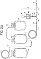
Fig. 2A is a plan view of another variant of a disposable blood collection or processing set including a sampling system; -
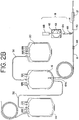
Fig. 2B is a plan view of another variant of a disposable blood collection or processing set including a sampling system; -
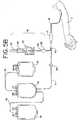
Fig. 2C is a plan view of another variant of a disposable blood collection or processing set including a sampling system; -
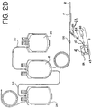
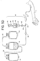
Fig. 2D is a plan view of another variant of a disposable blood collection or processing set including a sampling system embodying the present disclosure; -
Fig. 3 is a perspective view of a sampling system; -
Fig. 4 is a perspective view of the sampling system ofFig. 3 with an another embodiment of a holder; -
Fig. 5A is a diagram showing one step in the method of obtaining a blood sample in accordance with the present disclosure; -
Fig. 5B is a diagram showing the step of filling a sample container with blood; -
Fig. 5C is a diagram showing the steps of isolating the blood sampling system from the remainder of the processing set and collecting blood in the collection container; and -
Fig. 5D is a diagram showing the step of withdrawing the blood sample from the sampling container and collecting it in a sampling tube (i.e., sampling). -
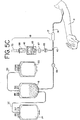
Fig. 6 is a plan view of another version of a blood collection and processing set with a sampling system embodying the present invention. -
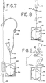
Fig. 7 is a partial, plan view of a blood collection and processing set with a sampling system embodying the present invention with a pre-attached sample tube holder; -
Fig. 8 is a partial plan view of the set ofFig. 6 ; -
Fig. 9 is a partial plan view of the set ofFig. 6 showing the preferred orientation of the sample container during sampling; -
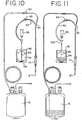
Fig. 10 is a plan view of the sample container filling step in the method of the present disclosure ; -
Fig. 11 is a plan view of a later blood collection step in the method of the present disclosure; -
Fig. 12 is a plan view of the sample tube filling step in the method of the present disclosure; -
Fig. 13 is a plan view of one embodiment of the sample container of the present disclosure; and -
Fig. 14 is a plan view of an alternative embodiment of a sample container of the present disclosure. - Turning now to
Fig. 1 of the drawings, the present disclosure may be embodied in a liquid flow conduit set such as a disposable processing set 10, which is particularly suitable for use in the manual collection of blood from adonor 11. The illustrateddisposable set 10 may include a needle such asvenipuncture needle 12, andplastic tubings needle 12 to a collection container such as a flexibleplastic container 16. Aneedle protector 17 may also be provided for retraction and storage ofneedle 12 after use. - The blood processing set 10 may include a single
blood collection container 16 or, more preferably, as shown inFigure 1 , may be a multiple blood container system includingadditional containers sampling system 18, described in more detail below. - As set forth above, blood processing set 10 may include a
primary container 16 and one or more integrally attachedtransfer containers donor tubings venipuncture needle 12.Container 16 typically includes a suitable anticoagulant such as citrate phosphate dextrose (CPD), citrate phosphate dextrose adenine (CPDA) or acid citrate dextrose (ACD). -
Containers primary container 16 by integrally attachedtransfer tubing Containers container 16 may be centrifuged to separate the blood into layers of such components. The heavier cellular components, such as red blood cells, settle to the bottom of thecontainer 16 and the lighter, less dense components, such as plasma (with or without platelets), remain in the top layer. The components may then be separated by expressing the lighter components throughtransfer tubing 30 and intocontainer 20. Likewise, the heavier components may be expressed throughtransfer tubing 32 tocontainer 24. Such "top and bottom" separation techniques and disposable processing sets are well known and are available from Baxter Healthcare Corporation of Deerfield, Illinois under the name Optipac®. - Of course, it will be understood that the present disclosure is not limited to the processing sets shown in the figures and that processing sets having different container and tubing configurations are also within the scope of the present disclosure . For example, a multiple container system wherein
tubing segments container 16 at or near the top ofcontainer 16 may also be used.Container 24 may include a volume of a preservative or storage solution which is introduced intocontainer 16 and combined with separated red cells after plasma has been expressed tocontainer 20. Such blood processing sets are also available from Baxter Healthcare Corporation. -
Containers U.S. Patent Nos. 5,167,657 ,5,100,401 and5,026,347 . Containers made from polyvinyl chloride plasticized with citrate ester or other plasticizers are available from Baxter Healthcare Corporation of Deerfield, Illinois. Alternatively, and depending in part on the blood components to be stored, containers may be made from other materials such as polyolefin materials with or without plasticizer. - Turning now to the sampling system, as shown in
Figure 1 ,sampling system 18 may be integrally attached to the disposable processing set 10 at Y-connector 40. In general, and as shown in greater detail inFig. 3 ,sampling system 18 may include acontainer 42 having aninlet port 46 andoutlet port 50.Container 42 further includes aninterior chamber 54 defined bywalls 56 and 58 (Fig. 4 ) that are joined together in a facing arrangement.Walls Container 42 may be made by heat sealing togetherwalls walls bushing 47, (typically made of polyvinyl chloride) may be included at, for example,inlet port 46, and may also be RF sealed towalls - Container 42 (or the
walls 56 and 58) may typically be made of any conventional medical grade plastic material that is sterilizable by known sterilization techniques including autoclaving. One such preferred material is polyvinyl chloride with a plasticizer, such as a citrate ester (e.g. n-butyryltri-n-hexyl citrate), as substantially described above. Of course, other known plasticizers such as TEHTM and DEHP may also be used. In one example, the material used to makewalls -
Container 42 may also include an internal flow path that extends substantially into theinterior chamber 54 ofcontainer 42. In a preferred embodiment, the internal flow path may be defined by aplastic tube 43. As shown inFigs. 3-4 , in the preferred embodiment, one end oftube 43 is attached tocontainer 42 and may provideoutlet port 50. Preferably,tube 43 may be RF sealed tocontainer walls Tube 43 may be made of any typical medical grade material such as polyvinyl chloride with a plasticizer.Tube 43 extends substantially intointerior chamber 54 and terminates nearinlet port 46. Extendingtube 43 substantially intointerior chamber 54 assures that the end oftube 43 will reside within or near the liquid insidecontainer 42, making it less likely that air will be present when liquid (such as blood) is withdrawn fromcontainer 42 into a sampling tube.Tube 43 also separateswalls chamber 54 and assists in preventingwalls Figure 3 , in a preferred embodiment,interior chamber 54 may be generally circular (i.e., have a generally circular profile). This may allow, for more complete drainage ofcontainer 42 by eliminating corners where the blood may otherwise reside. In one embodiment,interior chamber 54 ofcontainer 42 may have a volume of approximately 20-100 ml and, more preferably, approximately 30-70 ml and, in some countries, a minimum volume of approximately 50 ml. - As further shown in
Figure 3 ,sampling device 18 may includetubing segment 62 attached tocontainer 42 atinlet port 46.Tubing segment 62 may be attached tocontainer 42 and, more specifically, bushing 47 by, for example, solvent bonding. The other end of tubing segment may be bonded to Y-connector 40.Tubing segments 62 may further include anopenable barrier 64 such as a frangible cannula or connector of the type described inU.S. Patent No. 5,330,464 , assigned to the assignee of the present application.Barrier 64 preserves the sterility of the flow path defined bytubing segment 62. Flow restrictor clamps, such as Roberts-type clamps 65 and 66 (Fig. 1 ), ontubing segment 62 andtubing segment 15 may also be provided to allow for flow control through blood processing set 10 by the technician. In one embodiment, clamp 65 ontubing segment 62 may be a substantially irreversibly closeable clamp of the type described inWO 03/063 945 -
Sampling system 18 may further include a receptacle orholder 68 as shown inFigure 3 . As will be described in more detailed below,holder 68 is adapted to receive ablood sampling tube 70.Holder 68 may be attached tocontainer 42 atoutlet port 50 to provide an integrated system. In one embodiment,holder 68 includes distalluer end 69 which may be mated with and bonded tooutlet port 50 prior to heat sterilization. More preferably,distal end port 69 may be bonded totube 43. Subsequent heat sterilization forms a bond between the polycarbonate material ofdistal end 69 and, for example,tube 43. Of course, other ways ofbonding holder 68 tocontainer 42, such as solvent bonding, may also be used. Alternatively,holder 68 may be separately provided and attached tooutlet port 50 at the time of use, or used to access an access site that communicates withcontainer 42. - In one embodiment (shown in
Fig. 3 ),holder 68 may have acentral body portion 71, generally in the shape of a hollow cylinder.Holder 68 is open at its proximal end to allow for insertion ofsampling tube 70.Holder 68 may be made of any plastic sterilizable material. Holders of the type generally discussed above are available from, for example, Becton-Dickinson Co. of Franklin Lakes, New Jersey. -
Holder 68 may include a piercingmember 74 as generally shown inFig. 3 (or Fig. 4 ). Piercingmember 74 may be a needle, cannula or other biocompatible device having a sharpened tip. As set forth above, piercingmember 74 includes a piercingend 76. Piercingmember 74 may be made of any material of sufficient strength such as metal or plastic. In addition, end 76 of piercingmember 74 may be enclosed within a protective sheath 80. Protective sheath 80 may preferably be made of a flexible material, such as latex, which is capable of being penetrated by the tip of piercingmember end 76. Also protective sheath 80 should be sufficiently resilient to return to its original shape (covering end 76) upon withdrawal ofsampling tube 70. Holder may include a cap, such as a flip-cap, of the type shown and described in U.S. Patent Application Publication No.US2004/0082899 . - During a collection procedure, a
sampling tube 70, as shown inFig. 3 , may be inserted into the interior ofholder 68. As shown inFigs. 3 and 4B ,tube 70, which is typically a vacuum sealed tube, may itself include apiercable cap 84. Such tubes are available from the Becton-Dickinson Co. of Franklin Lakes, New Jersey and are sold under the trade name VACUTAINER®. - The method of collecting a blood sample from a donor during a blood donation using the blood processing system generally described above will now be described. In one embodiment, at the outset of the donation procedure, disposable processing set 10 may be provided with
clamps Fig. 5A . Next, optionalfrangible connector 64 is opened andneedle 12 is inserted into the arm of thedonor 11. As further shown inFig. 5B , clamp 65 is opened and blood from the donor is allowed to flow into container orpouch 42. Alternatively, in some embodiments, clamp 65 may be opened prior to venipuncture. - Once a sufficient volume of blood for sampling has been collected,
sampling system 18 may be isolated from the remainder of the processing set 10 by heat sealingtubing segment 62 in ways that are known to those of skill in the art. One device that may be used for sealing is the tubing sealing device known as the Hematron®, sold by Baxter Healthcare Corporation. Alternatively,line 62 may be sealed by a metal retaining clip or other means known to those of skill in the art. After isolation byseal 67,clamp 65 is closed and theclamp 66 is opened to allow blood flow intocontainer 16 as shown inFig. 5C . Of course, it will also be appreciated by those of skill in the art that in some embodiments, clamp 65 may be closed and clamp 66 or other flow control device (e.g., frangible 164 inFigs. 6 and7 ) may be opened (to allow blood flow into container 16) before heat sealingtubing segment 62. - In any event, once
sampling system 18 has been isolated from the remainder of the blood processing set 10, blood collected insample container 42 may be transferred to asampling tube 70 as shown inFig. 5D and in more detail inFigs. 3 and 4C . Samplingtube 70 is inserted into the interior ofholder 68 so thatcap 84 oftube 70 is pierced by the piercingend 76 of piercingmember 74, as generally shown inFig. 4B . As shown inFigs. 3 and 4 , it is preferred thatsampling tube 70 be introduced intoholder 68 in an inverted position so that blood flows up intotube 70. Applicants have discovered that such blood flow results in less hemolysis of red blood cells as compared to other collection techniques where the blood is allowed to drip into an upright tube. - Finally, turning briefly to
Figs. 1A and2A-2D , the blood processing sets shown therein are variants of the processing set 10 ofFig. 1 . While thesampling systems 18 shown in these embodiments are similar to the sampling system described above, the processing sets differ, in general, in the presence and location ofopenable barriers 64, the orientation of certain components, the introduction and withdrawal of blood into and fromsample container 42 and the like. For example, the blood processing set shown inFig. 1A is virtually identical to the set ofFig. 1 with the exception that Y-connector 40 is oriented in the opposite direction (which may be desirable for packaging purposes). - In
Fig. 2A , an additionalopenable barrier 64 of the type described above may be included online 15. Inclusion ofbarrier 64 online 14 may prevent additional anticoagulant from enteringline 14 distal to Y-connector 40. A similar but alternative embodiment is shown inFig. 2B where an openable barrier 64a (such as a polyvinyl chloride frangible cannula) is located near the inlet port ofcontainer 16. In these embodiments,barrier 64 or 64A would be opened just prior to collection of blood incontainer 16. - In another embodiment, shown in
Fig. 2C , anopenable barrier 64 may be included online 14, but not online 62. In this embodiment,holder 68 preserves the sterility of the system. Finally, as shown inFig. 2D , a Y-site of the type described inU.S. Patent No. 5,372,143 may be used in combination with thesampling system 18 of the present disclosure. - More specifically,
sampling system 18, shown inFig. 2D , includes a sample container orpouch 42,tube 43 that extends substantially into theinterior chamber 54 ofpouch 42, and anaccess site 122 external tocontainer 42 through which blood from the donor is introduced intochamber 54.Chamber 54 is accessible bysample tube holder 68 throughaccess site 122 andtube 43, as described, for example, inU.S. Patent No. 5,372,143 . - The sampling systems shown in
Figs. 6 and7 are, in many respects, similar to thesampling system 18 ofFig. 2D , with some exceptions. In the embodiments ofFigs. 6 and7 ,access site 122 is spaced a pre-selected distance fromcontainer 42. In the embodiment ofFig. 6 , the spacing is provided byintermediate tube 126, although it will be appreciated by those of skill in the art that the spacing can also be provided by extending the length oftube 43. In a preferred embodiment, one end oftube 126 is joined to accesssite 122, and the other end is joined totube 43.Tube 126 may be joined to accesssite 126 andtube 43 in ways well known to those skilled in the art, such as, but not limited to, solvent bonding. Spacingaccess site 122 fromcontainer 42 provides the user greater flexibility in orientingcontainer 42 in a desired position relative to theaccess site 122 andsample tube holder 68 when performing the actual collection of blood in vacuum sealedtubes 70. Providing an access site spaced from the container allows the user to comfortably grasptube 126 and/oraccess site 122 and orient thepouch 42, such that it hangs down fromaccess site 122 as shown, for example, inFig. 9 . In this preferred orientation,tube 43 is substantially vertically disposed with its distal end residing in the reservoir of collected blood and away from air in the container. In that regard, it is preferred thataccess site 122 be spaced a sufficient distance fromcontainer 42 to allow the user to grasp the tube as also shown inFig. 9 . A tubing length that is too short may not provide enough room for the user to comfortably graspaccess site 122 and/ortube 126 and still orientcontainer 42 in the preferred position. On the other hand, excessive lengths of tubing separatingaccess site 122 andcontainer 42 also may not be desirable because they will provide too much space for air and are less compact for packaging purposes. A preferred distance betweenaccess site 122 andcontainer 42 may be anywhere between 1 and 5 inches and, more preferably, between about 2 and 3 inches. - Another advantage of spacing access site 122 a sufficient distance from
container 42 along the flow path between the two (i.e., by eitherintermediate tube 126 or an extended tube 43) is that it provides the user with the ability to stop the flow fromchamber 54 to accesssite 122 during the sampling process. Stopping the flow to accesssite 122 may be desirable where, for example,holder 68 fails or is blocked, requiring attachment of a new holder 68 (access device). Thus, the distance betweenaccess site 122 andcontainer 42 should be sufficient to accommodate a clamp (such asclamp 65 shown in phantom lines inFig. 8 ) or other flow control device. -
Fig. 7 is, in many respects, identical to the embodiment shown inFig. 6 , with the one exception thatholder 68 is pre-attached to accesssite 122 adapted for receiving theluer end 69 ofholder 68.Holder 68 may be pre-attached to a port ofaccess site 122 in ways previously described, such as, but not limited to, adhesion bonding caused by the applied heat of sterilization or solvent bonding. - In contrast to the embodiments of
Figs. 1 ,2A ,2B , and2C , in the embodiments ofFigs. 2D ,6 and7 , the flow path that extends substantially intointerior chamber 54 ofpouch 42 serves the dual function of a blood entry flow path and a blood withdrawal flow path. In fact, the flow path shown astube 43 inFigs. 2D ,6 and7 , orinternal flow passageway 143 inFig. 14 , provides the only access or flow path for the blood entering and exitingchamber 54. - For example, with the clamp 66 (in
Fig. 2D ), or frangible barrier 64 (inFigs. 6 and7 ) closed, the venipuncture is made, and clamp 65 is opened. A port ion of the blood from the donor flows intochamber 54 throughtube 43, as best seen inFig. 10 . Once thesample container 42 is filled to the desired level, clamp 65 is closed, and the main collection is allowed to proceed (by opening, i.e., breaking frangible member 164), as discussed above and shown inFig 11 .Line 62 may further be sealed by RF sealing or metal clips. At the time of sampling, i.e., collecting blood samples in vacuum sealedtubes 70, blood flows fromchamber 120 throughtube 43, throughholder 68, to vacuumsample tube 70, as shown inFig. 12 . - Allowing
tube 43 to serve as both the flow path for blood entering the container and the flow path for blood exiting the container provides advantages in addition to the benefits provided bytube 43 previously discussed (i.e. , providing substantially complete drainage and preventing wall collapse during sterilization). By providingtube 43 for both blood entry and blood withdrawal, the sampling systems shown inFigs. 2D and6 and7 ensure that air will not be introduced into the first vacuum sealed sample tube used in the sampling process, and that a full sample can be collected. - In other sampling systems and sampling operations for collecting a plurality of sample tubes that utilize a sample pouch, and separate access ports for blood introduction and blood withdrawal from the sample pouch, it is common for the first of the plurality of sample tubes to be underfilled. This is because resident air in the head space of the sample pouch and/or associated tubing is suctioned into the sample tube ahead of the blood. Such underfilled tubes may not be useable for sampling. In addition, introducing air into the sample tube may lead to hemolysis in the blood sample. Users of these systems have tried to overcome this problem by inverting the sample pouch to avoid collecting air, or by accessing the sample pouch from below or from the side of the sample pouch. Having to turn or otherwise manipulate the sample pouch, or access it from a position other than the top of the pouch can be awkward, burdensome and, in the end, unsatisfactory from the standpoint of the user.
- In accordance with the present disclosure, air in the head space of
container 42 is bypassed bytube 43, which extends substantially into theinterior chamber 54 and, therefore, into the reservoir of collected blood as seen, for example, inFig. 11 . As for air that may reside intube 43, any such resident air is displaced fromtube 43 and intochamber 54 by incoming blood. During the initial draw of blood intocontainer 42, the initial flow of blood pushes any air residing intube 43 intochamber 54. As a result,tube 43 is substantially free of air. Thus, the first or initial sample tube 70 (i.e., the first aliquot or sample of blood to be removed from the sample pouch), inserted intoholder 68 will substantially receive blood from the sample pouch, and not resident air fromtube 43. This way, an underfilled first sample tube is avoided and the initial and subsequent sample tubes may be substantially free of excess air and be filled with a desired amount of blood. Avoidance of air also reduces the risk of hemolysis. - As shown in
Fig. 13 ,container 42, and more specifically,chamber 54 ofcontainer 42, may be shaped to provide a well 130 near the base ofchamber 54. Well 130 provides a funneling effect for blood inchamber 54, further ensuring that as much of the blood for sampling can be drained fromcontainer 42. As shown inFig. 13 , and as previously discussed,tube 43 extends substantially into the interior chamber ofcontainer 42. It is preferred that the distal end oftube 43 extend into thewell 130. By extending the distal end oftube 43 into the well 130, drainage of blood from the container is improved. In addition, thesides 132 of well 30 also assist in retaining the distal end oftube 43 withinwell 130. -
Container 42 may also include embossed, printed, or otherwise marked gradations along the side peripheral sealed edge ofcontainer 42. Embossed indicia may be provided at the time of sealing together container walls. The indicia orgradations 134 provide the user with a visual indication of the volume of blood for sampling.Indicia 134 for indicating the volume within the sample pouch are also shown in the container ofFig. 14 described below. -
Fig. 14 shows an alternative embodiment of asample container 142 with a flow path through which blood is introduced intochamber 120 and through which blood is withdrawn during sampling. InFig. 14 ,container 142 includes two oppositely facing walls sealed together substantially along their peripheries byperipheral seal 140. An opening is provided through which blood is introduced and withdrawn. The opening may be a short length of plastic tubing (sealed to the facing walls) that provides aport 145 to whichtube 126 may be attached to provide flow communication betweenaccess site 122 and flowpath 143. Alternatively,tube 126 may have one end attached to accesssite 122 and its other end sealed tocontainer 142. - As shown in
Fig. 14 ,internal flow path 143 extends substantially intointerior chamber 120.Internal flow path 143 may be defined by a portion ofperipheral seal 140 and aninterior seal 146 spaced fromseal 140. Distal end 148 ofinterior seal 146 extends to point spaced from bottomperipheral seal 140a. -
Interior chamber 120 ofpouch 142 shown inFig. 14 may include asloped bottom 150 formed bybottom seal 140a to direct blood toward the distal end ofinternal flow path 143, thereby improving drainage frompouch 142 ofFig. 14 . The walls ofcontainer 142 may be made of a plastic material that will not stick together during sterilization and/orcontainer 142 may be provided with ribs or other means (that will be known to those skilled in the art) to prevent sticking of the walls during sterilization. - Whether the sample container is provided with a tube (e.g., tube 43) or other flow path (e.g., internal flow path 143), because the entry and withdrawal flow paths are one in the same, elimination of excess air from the vacuum sample tube can be accomplished without inversion of the sample container 42 (or 142) and without having to access the sample container from a location other than the top of the container.
- The disposable processing set and sampling system of the present disclosure provide many benefits. One benefit is that a blood sample may be obtained prior to the donation while still preserving the sterility of flow path between the donor and collection container. Specifically, as described above, a blood sample may be collected in container 42 (or 142), which container may then be isolated from the remainder of the system (by, for example, sealing or clipping). Once
container 42 has been isolated, a sampling tube may be introduced into the holder of the sampling system without the risk that bacteria or other foreign substances qn the tube will contaminate the rest of the blood processing set, includingflow path 14. - Another advantage is that blood samples can be collected without the introduction of excess air into the vacuum sample tube, making each collected sample, including the initial sample, useable for sampling and less likely to result in hemolysis of the blood cells caused by air.
- An advantage of pre-donation sampling is that bacteria or foreign substances that may be present on the donor's skin will not be transmitted to
collection container 16, but will be diverted to samplingcontainer 42. - Another advantage of pre-donation sampling is that it allows for collection of sample for testing, even if the donation is not completed.
- Another advantage of pre-donation sampling is that it may provide a more accurate profile of the donor's blood, particularly regarding the hemoglobin level of the donor. For example, during donation, the loss of blood volume in the donor is compensated by plasma. This compensation by plasma typically lowers the hematocrit of the donor's blood. If the sample is taken after donation, the donor hematocrit may be lower (by possibly as much as 0.5g/dL) than it otherwise would be if the sample is collected prior to donation.
- The present disclosure provides additional advantages, whether used for pre-donation or post-donation sampling. One advantage is the reduced risk of tubing or donor vein collapse as described above.
Container 42 acts as a buffer between the sampling tube and tube or vein. Thus, any suction forces generated by introduction of the vacuum sealed tube will be absorbed by thecontainer 42 and not tube or donor vein. - Of course, there may be other advantages of the present system not discussed herein which will be apparent to those of skill in the art.
Claims (7)
- A biological fluid sampling system comprising:a plastic container (42) comprising two walls joined together in a facing arrangement, said walls defining an interior chamber (54):characterized by:a sample access site (22) external to and spaced from said container (42) by a preselected distance:a plastic tube (43 within said plastic container defining an internal flow path communicating with said access site (122) and extending substantially into said interior chamber (54), said internal flow path providing the only path for blood flow to and from said chamber (54).
- The sampling system of Claim 1 wherein the sample access site (22) is spaced from the container (42) by an intermediate tube (126) defining a flow path with one end of said tube communicating with said sample access site (122) and the other end communicating with said plastic tube (43) defining said internal flow path
- The sampling system of Claim 1 wherein said interior chamber (54) has a generally circular profile.
- The sampling system of Claim 3 therein said interior chamber (54) includes a fluid receiving well.
- The sampling system of Claim 4 wherein the distal end of said internal flow path (43) extending substantially into said interior chamber is disposed within said well.
- The sampling system of Claim 1 wherein at least one of said walls being generally translucent, including indicia thereon for indicating the volume of fluid within said chamber.
- The sampling system of Claim 1 comprising a vacuum tube holder pre-attached to said access site (122).
Applications Claiming Priority (2)
| Application Number | Priority Date | Filing Date | Title |
|---|---|---|---|
| US10/956,296 US7824343B2 (en) | 1999-07-29 | 2004-10-01 | Method and apparatus for blood sampling |
| PCT/US2005/034504 WO2006039251A2 (en) | 2004-10-01 | 2005-09-27 | Method and apparatus for blood sampling |
Publications (2)
| Publication Number | Publication Date |
|---|---|
| EP1793737A2 EP1793737A2 (en) | 2007-06-13 |
| EP1793737B1 true EP1793737B1 (en) | 2017-03-22 |
Family
ID=35520707
Family Applications (1)
| Application Number | Title | Priority Date | Filing Date |
|---|---|---|---|
| EP05802165.0A Active EP1793737B1 (en) | 2004-10-01 | 2005-09-27 | Apparatus for blood sampling |
Country Status (8)
| Country | Link |
|---|---|
| US (1) | US7824343B2 (en) |
| EP (1) | EP1793737B1 (en) |
| JP (1) | JP4632321B2 (en) |
| CN (1) | CN101090666A (en) |
| AU (1) | AU2005292258A1 (en) |
| CA (1) | CA2582301C (en) |
| MX (1) | MX2007003391A (en) |
| WO (1) | WO2006039251A2 (en) |
Families Citing this family (38)
| Publication number | Priority date | Publication date | Assignee | Title |
|---|---|---|---|---|
| US7435231B2 (en) * | 1999-07-29 | 2008-10-14 | Fenwal, Inc. | Biological sample device receiver |
| EP1377216A2 (en) * | 1999-07-29 | 2004-01-07 | Baxter International Inc. | Sampling tube holder for blood sampling system |
| ATE440541T1 (en) * | 2005-09-13 | 2009-09-15 | Edwards Lifesciences Corp | CLOSED BLOOD COLLECTION SYSTEM WITH ISOLATED PRESSURE MONITORING |
| US9004761B2 (en) * | 2006-05-01 | 2015-04-14 | Baxter International Inc. | Multiple chamber container with mistake proof administration system |
| JP4812574B2 (en) * | 2006-09-14 | 2011-11-09 | テルモ株式会社 | Blood collection device |
| JP4879704B2 (en) * | 2006-10-30 | 2012-02-22 | 川澄化学工業株式会社 | Blood collection initial flow removal bag, blood collection initial flow removal set and blood bag |
| US20080108955A1 (en) * | 2006-11-02 | 2008-05-08 | Blickhan Bryan J | Flow Controllers |
| US20080108954A1 (en) * | 2006-11-02 | 2008-05-08 | Jean-Marie Mathias | Flow Controllers |
| US8197420B2 (en) | 2006-12-18 | 2012-06-12 | Magnolia Medical Technologies, Inc. | Systems and methods for parenterally procuring bodily-fluid samples with reduced contamination |
| US8443824B2 (en) | 2007-10-09 | 2013-05-21 | Fenwal, Inc. | Fluid flow controller |
| US8323251B2 (en) | 2008-01-14 | 2012-12-04 | Fenwal, Inc. | Phlebotomy needle assembly and frangible cover |
| US20090218535A1 (en) * | 2008-02-27 | 2009-09-03 | Andres Pasko | Flow controllers for fluid circuits |
| EP2110149B1 (en) | 2008-03-28 | 2017-05-03 | Fenwal, Inc. | Winged needle assembly and frangible cover |
| US8864684B2 (en) | 2011-10-13 | 2014-10-21 | Magnolia Medical Technologies, Inc. | Fluid diversion mechanism for bodily-fluid sampling |
| WO2013063529A2 (en) * | 2011-10-26 | 2013-05-02 | Cash William Phillip | Micro-volume blood transfer device |
| WO2013137359A1 (en) * | 2012-03-14 | 2013-09-19 | テルモ株式会社 | Container for testing blood and blood sampling instrument |
| US9022951B2 (en) | 2012-05-30 | 2015-05-05 | Magnolia Medical Technologies, Inc. | Fluid diversion mechanism for bodily-fluid sampling |
| US9060724B2 (en) | 2012-05-30 | 2015-06-23 | Magnolia Medical Technologies, Inc. | Fluid diversion mechanism for bodily-fluid sampling |
| WO2014022275A1 (en) | 2012-08-01 | 2014-02-06 | Magnolia Medical Technologies, Inc. | Fluid diversion mechanism for bodily-fluid sampling |
| EP2889024B1 (en) * | 2012-08-27 | 2018-09-19 | Terumo Kabushiki Kaisha | Blood bag and blood bag system provided therewith |
| ES2878047T3 (en) | 2012-10-11 | 2021-11-18 | Magnolia Medical Technologies Inc | System for administering a fluid to a patient with reduced contamination |
| CA3136331C (en) | 2012-11-30 | 2024-05-21 | Magnolia Medical Technologies, Inc. | Syringe based fluid diversion mechanism for bodily-fluid sampling |
| CN107874786B (en) * | 2012-12-04 | 2020-11-24 | 木兰医药技术股份有限公司 | Device for taking a sample of body fluid from a patient |
| US10772548B2 (en) | 2012-12-04 | 2020-09-15 | Magnolia Medical Technologies, Inc. | Sterile bodily-fluid collection device and methods |
| CN108433732B (en) | 2013-03-12 | 2021-05-28 | 木兰医药技术股份有限公司 | Apparatus and method for selectively occluding a lumen of a needle body |
| WO2015134431A1 (en) | 2014-03-03 | 2015-09-11 | Magnolia Medical Technologies, Inc. | Apparatus and methods for disinfection of a specimen container |
| US10729366B2 (en) * | 2014-12-02 | 2020-08-04 | Fenwal, Inc. | Spherical biomedical sampling and mixing container |
| EP4331643A3 (en) | 2015-06-12 | 2024-04-17 | Magnolia Medical Technologies, Inc. | Devices and methods for syringe-based fluid transfer for bodily-fluid sampling |
| CN108366904B (en) | 2015-09-03 | 2020-12-01 | 木兰医药技术股份有限公司 | Apparatus and method for maintaining sterility of a sample container |
| ES2928560T3 (en) | 2015-10-08 | 2022-11-21 | Channel Medsystems Inc | Exhaust gas collection bag for cryogenic treatment |
| EP3421062A3 (en) * | 2017-06-30 | 2019-03-06 | Fenwal, Inc. | Fluid circuit having reduced plasticizer migration |
| WO2019055487A1 (en) | 2017-09-12 | 2019-03-21 | Magnolia Medical Technologies, Inc. | Fluid control devices and methods of using the same |
| EP3721086A4 (en) | 2017-12-07 | 2021-11-10 | Magnolia Medical Technologies, Inc. | Fluid control devices and methods of using the same |
| EP3632484A1 (en) | 2018-10-04 | 2020-04-08 | Fenwal, Inc. | Methods and systems for collecting samples in a photopheresis procedure |
| JP7553455B2 (en) | 2019-02-08 | 2024-09-18 | マグノリア メディカル テクノロジーズ,インコーポレイテッド | Apparatus and method for bodily fluid collection and distribution - Patents.com |
| EP3938108B1 (en) | 2019-03-11 | 2023-08-02 | Magnolia Medical Technologies, Inc. | Fluid control devices |
| CN113813454B (en) * | 2021-08-30 | 2022-09-09 | 四川大学华西医院 | Method for collecting blood of organ donation donor |
| US20230084959A1 (en) * | 2021-09-07 | 2023-03-16 | Fenwal, Inc. | Blood Pack Donation System for Biomarker Collection During Whole Blood Donation |
Family Cites Families (176)
| Publication number | Priority date | Publication date | Assignee | Title |
|---|---|---|---|---|
| US2469641A (en) | 1947-01-04 | 1949-05-10 | Central Nat Bank Of Cleveland | Method of and machine for making unitary setup covered boxes |
| US2790815A (en) * | 1954-09-01 | 1957-04-30 | Minnesota Mining & Mfg | Process of making fluorinated acyl fluroides |
| US2950716A (en) * | 1956-01-23 | 1960-08-30 | Fenwal Lab Inc | Fluid handling method and apparatus |
| US3064647A (en) * | 1957-06-13 | 1962-11-20 | Baxter Laboratories Inc | Blood component separation method and apparatus |
| US2955595A (en) * | 1959-05-19 | 1960-10-11 | Fenwal Lab Inc | Therapeutic fluid sampling means |
| US3416528A (en) | 1959-08-17 | 1968-12-17 | Cutter Lab | Blood handling equipment |
| US3127892A (en) * | 1960-07-13 | 1964-04-07 | Baxter Laboratories Inc | Blood handling apparatus |
| FR1320869A (en) | 1962-01-31 | 1963-03-15 | Bottle with control tube | |
| US3187750A (en) * | 1963-01-15 | 1965-06-08 | Baxter Laboratories Inc | Multiple bag blood storage unit |
| US3217710A (en) | 1963-03-25 | 1965-11-16 | Abbott Lab | Blood collection and sampling apparatus provided with separable coupling means |
| US3342179A (en) | 1965-06-18 | 1967-09-19 | Abbott Lab | Blood collection and sampling apparatus having separable coupling means |
| US3469572A (en) | 1966-08-18 | 1969-09-30 | Becton Dickinson Co | Apparatus for taking multiple fluid samples |
| US3467095A (en) * | 1967-04-24 | 1969-09-16 | Eugene Ross Lab Inc | Blood collection set |
| FR1586087A (en) | 1968-12-10 | 1970-02-06 | ||
| US3494352A (en) | 1969-03-26 | 1970-02-10 | Becton Dickinson Co | Apparatus for taking multiple samples |
| US3654924A (en) * | 1970-05-14 | 1972-04-11 | Abbott Lab | Blood collection assembly |
| BE791340A (en) | 1972-01-06 | 1973-03-01 | Becton Dickinson Co | NEW METHOD AND APPARATUS FOR TAKING A CULTURE AND IDENTIFYING MICRO-ORGANISMS OF MOODS |
| US3817240A (en) | 1972-06-28 | 1974-06-18 | Becton Dickinson Co | Multiple sample needle assembly with one-way valve and blood flow indicator |
| US3931815A (en) | 1973-08-29 | 1976-01-13 | Jintan Terumo Company, Ltd. | Assembly having an adapter and a holder with a double ended needle |
| JPS5240621Y2 (en) * | 1974-07-31 | 1977-09-13 | ||
| US3945380A (en) * | 1974-08-21 | 1976-03-23 | Cutter Laboratories, Inc. | Plasmapheresis assembly |
| GB1583157A (en) * | 1976-05-07 | 1981-01-21 | Kenova Ab | Syringes |
| US4056101A (en) | 1976-09-01 | 1977-11-01 | Baxter Travenol Laboratories, Inc. | Means for reducing tissue thromboplastin in collected blood |
| US4121585A (en) | 1977-01-24 | 1978-10-24 | Becker Jr Karl E | Anti backflow injection device |
| US4197847A (en) * | 1977-03-31 | 1980-04-15 | Isaac Djerassi | Method and apparatus for collecting transfusable granulocytes |
| US4296759A (en) | 1977-06-27 | 1981-10-27 | Sherwood Medical Industries Inc. | Blood collection device and method with anti-backflow means |
| US4181140A (en) * | 1978-02-10 | 1980-01-01 | Baxter Travenol Laboratories, Inc. | Frangible resealable closure for a flexible tube having hold open means |
| US4294247A (en) * | 1977-07-25 | 1981-10-13 | Baxter Travenol Laboratories, Inc. | Frangible, resealable closure for a flexible tube |
| US4140108A (en) | 1977-08-10 | 1979-02-20 | Becton, Dickinson And Company | Blood collection assembly |
| US4212308A (en) | 1977-12-27 | 1980-07-15 | Becton, Dickinson And Company | Parallel-flow one-way blood sampling device |
| US4195632A (en) * | 1978-05-03 | 1980-04-01 | Cutter Laboratories, Inc. | Fluid flow valve |
| US4320769A (en) | 1978-05-19 | 1982-03-23 | Becton, Dickinson And Company | Universal holder for blood collecting tubes |
| US4307731A (en) | 1978-06-15 | 1981-12-29 | Becton, Dickinson And Company | Multiple sampling needle having one-way valve |
| US4253458A (en) | 1979-03-08 | 1981-03-03 | Baxter Travenol Laboratories, Inc. | Method and apparatus for collecting blood plasma |
| US4270534A (en) * | 1979-08-08 | 1981-06-02 | Baxter Travenol Laboratories, Inc. | Frangible valve assembly for blood bags and the like |
| US4295477A (en) | 1979-08-15 | 1981-10-20 | Becton, Dickinson And Company | Multiple sampling device having molded valve and hub |
| US4340049A (en) | 1979-10-18 | 1982-07-20 | Baxter Travenol Laboratories, Inc. | Breakaway valve |
| US4386622A (en) * | 1979-10-18 | 1983-06-07 | Baxter Travenol Laboratories, Inc. | Breakaway valve |
| US4256120A (en) | 1980-01-07 | 1981-03-17 | Sherwood Medical Industries Inc. | Fluid sample collection device |
| US4407660A (en) * | 1981-09-08 | 1983-10-04 | Baxter Travenol Laboratories, Inc. | Plasmapheresis assembly and associated fluid manifold |
| JPS58206752A (en) * | 1982-05-28 | 1983-12-02 | テルモ株式会社 | Connector structure of medical instrument |
| JPS58206759A (en) * | 1982-05-28 | 1983-12-02 | テルモ株式会社 | Medical container |
| US4670013A (en) * | 1982-12-27 | 1987-06-02 | Miles Laboratories, Inc. | Container for blood and blood components |
| US4547186A (en) | 1983-03-07 | 1985-10-15 | Bartlett Robert H | Autotransfusion system |
| JPS59166162A (en) | 1983-03-11 | 1984-09-19 | テルモ株式会社 | Medical needle and medical instrument having same |
| JPS607833U (en) * | 1983-06-27 | 1985-01-19 | テルモ株式会社 | blood bag device |
| JPS6029150A (en) | 1983-07-26 | 1985-02-14 | テルモ株式会社 | Medical liquid collecting apparatus |
| US4637934A (en) * | 1984-04-12 | 1987-01-20 | Baxter Travenol Laboratories, Inc. | Liquid container with integral opening apparatus |
| US4586928A (en) * | 1984-10-09 | 1986-05-06 | Miles Laboratories, Inc. | Pivoting frangible valve for plastic bags |
| US4892537A (en) * | 1985-02-11 | 1990-01-09 | Miles Laboratories, Inc. | Bag for separation and isolation of blood components |
| WO1986004818A1 (en) | 1985-02-26 | 1986-08-28 | Baxter Travenol Laboratories, Inc. | Fluid transfer system |
| US4994039A (en) * | 1985-11-15 | 1991-02-19 | Mattson Philip D | Apparatus and method for patients from a single donor or a restricted group of donors |
| AU578554B2 (en) * | 1986-01-24 | 1988-10-27 | Japanese Red Cross Society | Centrifugal method of separating blood components |
| WO1987006119A1 (en) * | 1986-04-07 | 1987-10-22 | Al Sioufi Habib | Anti-pathogenic blood collection system and method |
| USRE33924E (en) | 1986-07-16 | 1992-05-12 | Autologous Blood Corp. | Apparatus and method for storing and processing blood |
| US4804363A (en) * | 1986-07-16 | 1989-02-14 | Autologous Blood Corporation | Apparatus and method for storing and processing blood |
| US4763648A (en) | 1986-09-12 | 1988-08-16 | Migada, Inc. | Method and apparatus for arterial and venous blood sampling |
| US4900322A (en) * | 1986-09-22 | 1990-02-13 | Adams James D | Blood component pooling valve and kit |
| JPS63104916A (en) | 1986-10-22 | 1988-05-10 | Terumo Corp | Hemolysis inhibitor |
| AU607703B2 (en) | 1986-12-11 | 1991-03-14 | Terumo Kabushiki Kaisha | Blood sampling tube |
| US4900321A (en) * | 1986-12-12 | 1990-02-13 | Baxter International Inc. | Set with integrally formed sample cell |
| US4820297A (en) * | 1986-12-12 | 1989-04-11 | Baxter International Inc. | Fluid delivery system with integrally formed sample cell |
| US4798578A (en) * | 1987-02-13 | 1989-01-17 | Sherwood Medical Company | Autotransfusion device |
| US4790815A (en) | 1987-03-12 | 1988-12-13 | Baxter Travenol Laboratories, Inc. | Heat sterilizable plastic container with non-stick interior surfaces |
| JPS63230177A (en) * | 1987-03-19 | 1988-09-26 | テルモ株式会社 | Tube body openable by breakage |
| US4784650A (en) | 1987-03-23 | 1988-11-15 | Coburn Timothy J | Needle holder |
| US4865583A (en) | 1987-05-04 | 1989-09-12 | Tu Ho C | Combination blood sampling and intravenous infusion apparatus and method |
| US5114400A (en) | 1990-06-19 | 1992-05-19 | Lynn Lawrence A | Blood withdrawal apparatus and method |
| US5100376A (en) | 1987-08-26 | 1992-03-31 | Blake Joseph W Iii | Body-cavity drainage and autotransfusion system |
| US5098371A (en) * | 1987-10-24 | 1992-03-24 | Kawasumi Laboratories, Inc. | Switch bag type blood gathering set |
| DE3815643A1 (en) | 1988-05-07 | 1989-11-30 | Biotest Pharma Gmbh | DEVICE FOR SEPARATING COMPONENTS OF A LIQUID, IN PARTICULAR OF TOTAL BLOOD |
| JPH01291830A (en) | 1988-05-20 | 1989-11-24 | Terumo Corp | Blood-collecting tube holder |
| JPH0622614B2 (en) | 1988-06-21 | 1994-03-30 | テルモ株式会社 | Blood reservoir |
| US4911696A (en) * | 1988-06-27 | 1990-03-27 | Terumo Kabushiki Kaisha | Branch tube |
| US4943283A (en) | 1988-07-20 | 1990-07-24 | City Of Hope | Blood collecting apparatus with shielded needles |
| AU628786B2 (en) | 1988-07-26 | 1992-09-24 | Terumo Kabushiki Kaisha | Blood collector |
| DE3830649A1 (en) | 1988-09-09 | 1990-03-15 | Gimelli & Co Ag | ELECTRIC TOOTHBRUSH |
| US5002066A (en) * | 1988-12-22 | 1991-03-26 | Medex, Inc. | Blood sampling apparatus |
| US5046509A (en) * | 1988-12-30 | 1991-09-10 | Spacelabs, Inc. | Device for the conditioning, handling and measurement of blood |
| JP2821686B2 (en) | 1989-04-27 | 1998-11-05 | テルモ株式会社 | Blood bag and blood collection tube holding member for attaching blood bag |
| US5300060A (en) * | 1989-06-12 | 1994-04-05 | Miles Inc. | Blood bag system for separation and isolation of neocytes and gerocytes |
| US5141490A (en) * | 1989-06-25 | 1992-08-25 | Terumo Kabushiki Kaisha | Single-needle type plasma separation apparatus and plasma collection apparatus |
| FR2655532A1 (en) | 1989-12-08 | 1991-06-14 | R D Sarl | Device for taking a sample for a blood sample collection |
| US4997577A (en) | 1989-12-20 | 1991-03-05 | Baxter International Inc. | Systems and methods for removing undesired matter from blood cells |
| US5102407A (en) | 1990-03-13 | 1992-04-07 | Miles Inc. | Blood separation system |
| JP2838725B2 (en) * | 1990-05-02 | 1998-12-16 | テルモ株式会社 | Blood collection equipment |
| US5122129A (en) * | 1990-05-09 | 1992-06-16 | Olson Donald J | Sampler coupler device useful in the medical arts |
| DK119490D0 (en) * | 1990-05-14 | 1990-05-14 | Unes As | Apparatus for the preparation of a concentrate of coagulation factors, such as the fibrinogen, from a blood portion |
| US5048537A (en) | 1990-05-15 | 1991-09-17 | Medex, Inc. | Method and apparatus for sampling blood |
| US5123570A (en) * | 1990-05-25 | 1992-06-23 | Dubow Brian C | Container for inverted dispensing |
| US5084034A (en) * | 1990-06-08 | 1992-01-28 | Tufts University | Method for sampling body fluids |
| JPH0628137Y2 (en) | 1990-06-21 | 1994-08-03 | 株式会社ニッショー | Closure in a flexible tube |
| US5203775A (en) | 1990-09-18 | 1993-04-20 | Medex, Inc. | Needleless connector sample site |
| JP2980663B2 (en) * | 1990-10-05 | 1999-11-22 | テルモ株式会社 | Bag connection |
| US5154716A (en) * | 1990-11-06 | 1992-10-13 | Miles Inc. | Bottom blood bag separation system |
| US5176655A (en) | 1990-11-08 | 1993-01-05 | Mbo Laboratories, Inc. | Disposable medical needle and catheter placement assembly having full safety enclosure means |
| IT1244805B (en) * | 1990-11-22 | 1994-09-05 | Roerig Farmaceutici Italiana S | SINGLE NEEDLE PLASMAFERESIS EXTRA-BODY CIRCUIT |
| US5061365A (en) * | 1991-01-22 | 1991-10-29 | Utterberg David S | Medical fluid flow set |
| US5167656A (en) | 1991-01-22 | 1992-12-01 | Baxter International Inc. | Blood container having lay-flat sample reservoir |
| US5259841A (en) | 1991-02-25 | 1993-11-09 | Gemini Trade Overseas Ltd. | Safety syringe |
| DE69203828T2 (en) * | 1991-05-08 | 1996-05-02 | Baxter Int | METHOD FOR TREATING PRODUCTS OF RED BLOOD CELLS FOR LONG-TERM STORAGE FREE OF MICRO-ORGANISMS. |
| US5269946A (en) | 1991-05-22 | 1993-12-14 | Baxter Healthcare Corporation | Systems and methods for removing undesired matter from blood cells |
| US5128048A (en) | 1991-05-22 | 1992-07-07 | Baxter International Inc. | Systems and methods for removing undesired matter from blood cells |
| US5180504A (en) * | 1991-05-22 | 1993-01-19 | Baxter International Inc. | Systems and methods for removing undesired matter from blood cells |
| JPH05131018A (en) * | 1991-11-11 | 1993-05-28 | Terumo Corp | Bag connection body and manufacture thereof |
| US5395349A (en) | 1991-12-13 | 1995-03-07 | Endovascular Technologies, Inc. | Dual valve reinforced sheath and method |
| JPH0716484B2 (en) | 1992-03-24 | 1995-03-01 | 株式会社ニッショー | Blood collection device adapter |
| IL101680A (en) | 1992-04-23 | 1995-08-31 | Travenol Lab Israel Ltd | Blood sampling device |
| GB9218581D0 (en) * | 1992-09-02 | 1992-10-14 | Pall Corp | Removal of unwanted fluids from processed blood products |
| US5345070A (en) | 1992-09-25 | 1994-09-06 | Cobe Laboratories, Inc. | Radio frequency tubing sealer |
| US5454806A (en) * | 1992-11-06 | 1995-10-03 | Terumo Kabushiki Kaisha | Medical device |
| US5372143A (en) * | 1992-11-20 | 1994-12-13 | Baxter International Inc. | Blood sampling system with luer adaptor |
| US5270003A (en) | 1992-11-20 | 1993-12-14 | Baxter International Inc. | Blood sampling system |
| JP3283641B2 (en) * | 1993-06-29 | 2002-05-20 | テルモ株式会社 | Blood processing method |
| US5523004A (en) * | 1992-12-04 | 1996-06-04 | Terumo Kabushiki Kaisha | Method for treatment of blood using a blood bag |
| US5505716A (en) * | 1993-02-02 | 1996-04-09 | Simmet; Ludwig O. | Embryo collector |
| US5527472A (en) * | 1993-06-14 | 1996-06-18 | Baxter International Inc. | Closed systems and methods for removing undesired matter from blood cells |
| US5591337A (en) * | 1993-09-14 | 1997-01-07 | Baxter International Inc. | Apparatus for filtering leukocytes from blood cells |
| IT1260685B (en) * | 1993-09-29 | 1996-04-22 | Sorin Biomedica Spa | BLOOD CONTAINMENT DEVICE |
| US5836619A (en) | 1993-11-05 | 1998-11-17 | Migada, Inc. | Manually-severable coupling device, and medical infusion assembly including same |
| US5458593A (en) | 1993-11-24 | 1995-10-17 | Bayer Corporation | Dockable bag system and method |
| US5464397A (en) | 1994-01-11 | 1995-11-07 | Powers Jr.; Carleton A. | Bacteria valve |
| US5545339A (en) | 1994-02-25 | 1996-08-13 | Pall Corporation | Method for processing biological fluid and treating separated component |
| DE9405166U1 (en) * | 1994-03-26 | 1994-05-26 | Krebs, Peter, Dr., 78048 Villingen-Schwenningen | Spinal cannula with transparent handle |
| US5431174A (en) * | 1994-04-04 | 1995-07-11 | Via Medical Corporation | Method of fluid delivery and collection |
| JP3009944U (en) * | 1994-06-27 | 1995-04-18 | 健次 森 | Infusion set with dissolution / drip set |
| US5702383A (en) | 1994-07-01 | 1997-12-30 | Baxter International Inc. | Blood component collection systems and methods using an integral sampling device |
| US5776338A (en) * | 1994-08-18 | 1998-07-07 | Biofil S.R.L. | Disposable sterile apparatus for blood filtration with a system for optimizing the recovery of blood between pouches |
| WO1996014741A2 (en) * | 1994-11-14 | 1996-05-23 | Pall Corporation | Long-term blood component storage system and method |
| US5789147A (en) * | 1994-12-05 | 1998-08-04 | New York Blood Center, Inc. | Method for concentrating white cells from whole blood by adding a red cell sedimentation reagent to whole anticoagulated blood |
| US5772608A (en) * | 1994-12-28 | 1998-06-30 | The Research Foundation Of State University Of New York | System for sampling arterial blood from a patient |
| US5573526A (en) | 1995-05-08 | 1996-11-12 | Minntech Corporation | Soft shell reservoir |
| US5665074A (en) | 1995-09-28 | 1997-09-09 | Liebel Flarsheim Company | Limited backflow reflux valve |
| US5885261A (en) * | 1996-04-25 | 1999-03-23 | C. R. Bard, Inc. | Autotransfusion system and method |
| US5897526A (en) * | 1996-06-26 | 1999-04-27 | Vaillancourt; Vincent L. | Closed system medication administering system |
| US6387069B1 (en) * | 1996-09-23 | 2002-05-14 | Dsu Medical Corporation | Blood set priming method and apparatus |
| US7166084B2 (en) * | 1996-09-23 | 2007-01-23 | Dsu Medical Corporation | Blood set priming method and apparatus |
| EP0970183B1 (en) * | 1997-03-20 | 2005-10-05 | Allen C. Barnes | Micropathological patient replica based on unadulterated whole blood |
| DE19712298C2 (en) | 1997-03-24 | 1999-05-20 | Fresenius Ag | Device and method for separating blood into blood components |
| CN2301263Y (en) | 1997-06-13 | 1998-12-23 | 郑雷法 | Plasma separating bowl |
| US5879318A (en) * | 1997-08-18 | 1999-03-09 | Npbi International B.V. | Method of and closed system for collecting and processing umbilical cord blood |
| US6491679B1 (en) | 1997-10-20 | 2002-12-10 | Rodney Okamoto | System for infusing intravenous nutrition solutions |
| US6187198B1 (en) * | 1997-10-21 | 2001-02-13 | Dsu Medical Corporation | Automatic priming of connected blood sets |
| US6071270A (en) | 1997-12-04 | 2000-06-06 | Baxter International Inc. | Sliding reconstitution device with seal |
| US6592613B1 (en) * | 1998-01-16 | 2003-07-15 | Terumo Kabushiki Kaisha | Blood collecting apparatus and blood collecting method using blood collecting apparatus |
| JP3776227B2 (en) | 1998-01-16 | 2006-05-17 | テルモ株式会社 | Blood collection instrument |
| US6132413A (en) * | 1998-03-06 | 2000-10-17 | Baxter International Inc. | Breakable cannula assemblies and methods for manipulating them |
| US6123859A (en) * | 1998-04-22 | 2000-09-26 | Hemasure Inc. | Method for in-line filtering biological liquid |
| ES2243023T3 (en) * | 1998-05-19 | 2005-11-16 | Terumo Kabushiki Kaisha | METHOD OF ELIMINATION OF WHITE BALLOONS. |
| US6267745B1 (en) * | 1998-05-21 | 2001-07-31 | Baxter International Inc. | Confined air tube and methods for handling air in closed blood processing systems |
| US6669905B1 (en) | 1998-05-21 | 2003-12-30 | Baxter International Inc. | Systems and methods for collecting plasma that is free or virtually free of cellular blood species |
| US6358420B2 (en) * | 1998-06-01 | 2002-03-19 | Baxter International Inc. | Blood collection method employing an air venting blood sample tube |
| DE19828650C2 (en) * | 1998-06-26 | 2000-10-19 | Fresenius Medical Care De Gmbh | Connector element with integrated shut-off element |
| AUPP676898A0 (en) * | 1998-10-26 | 1998-11-19 | Noble House Group Pty Ltd | Sampling first in blood collection |
| US6126618A (en) * | 1999-01-14 | 2000-10-03 | Baxter International Inc. | Apparatus for obtaining liquid samples |
| US6969419B1 (en) | 1999-05-06 | 2005-11-29 | Segars California Partners Lp | Method for removing gas bubbles from a fluid-containing chamber |
| US6267564B1 (en) | 1999-05-12 | 2001-07-31 | Sims Deltec, Inc. | Medical reservoir bag and system |
| US6287265B1 (en) * | 1999-06-23 | 2001-09-11 | Cindy L. Gleason | Blood collection kit |
| FR2795647B1 (en) | 1999-06-30 | 2004-05-07 | Maco Pharma Sa | POCKET ASSEMBLY FOR RECEIVING BIOLOGICAL FLUID AND HIGHLIGHTING POSSIBLE BIOLOGICAL FLUID CONTAMINATION |
| US20030176813A1 (en) * | 1999-07-29 | 2003-09-18 | Jean-Marie Mathias | Biological fluid sampling apparatus |
| US7435231B2 (en) * | 1999-07-29 | 2008-10-14 | Fenwal, Inc. | Biological sample device receiver |
| US6387086B2 (en) * | 1999-07-29 | 2002-05-14 | Baxter International Inc. | Blood processing set including an integrated blood sampling system |
| EP1377216A2 (en) * | 1999-07-29 | 2004-01-07 | Baxter International Inc. | Sampling tube holder for blood sampling system |
| RU2149930C1 (en) * | 1999-07-30 | 2000-05-27 | Рябков Данила Витальевич | Method of surface modification of metal articles and device for method realization |
| US6325775B1 (en) | 1999-09-03 | 2001-12-04 | Baxter International Inc. | Self-contained, transportable blood processsing device |
| US6364847B1 (en) * | 1999-10-07 | 2002-04-02 | Sunscope International, Inc. | Blood sampling device |
| US6517508B1 (en) * | 1999-11-03 | 2003-02-11 | Dsu Medical Corporation | Set for blood processing |
| US6632201B1 (en) | 1999-11-17 | 2003-10-14 | Baxter International Inc. | Locking needle protector |
| IL134528A (en) | 2000-02-14 | 2005-05-17 | Teva Medical Ltd | Donor blood sampling system |
| CN1420796A (en) | 2000-03-31 | 2003-05-28 | 巴克斯特国际公司 | Systems and methods for collecting leukocyte-reduced blood components, including plasma that is free or virtually free of cellular blood species |
| US6267664B1 (en) * | 2000-09-01 | 2001-07-31 | Alphonse J. Vandale | Exterior side view mirror and side window defogger system |
| FR2825261B1 (en) | 2001-06-01 | 2003-09-12 | Maco Pharma Sa | PLACENTAL BLOOD COLLECTION LINE COMPRISING A RINSING POCKET |
| US20040019344A1 (en) * | 2002-07-26 | 2004-01-29 | Grant Peterson | Integrated, one-piece sampling connector unit |
| US7384416B2 (en) | 2002-08-12 | 2008-06-10 | Macopharma | Device and method for irreversible closure of fluid communication in a container system |
| FR2856285B1 (en) | 2003-06-20 | 2005-08-05 | Maco Pharma Sa | POCKET SYSTEM FOR THE COLLECTION AND SAMPLING OF A BIOLOGICAL FLUID FROM A DONOR |
| DE20311868U1 (en) | 2003-07-30 | 2003-12-24 | Bachmann, Walter, Dr.Med. | Closed system of container and tube for safe removal and disposal of body fluids in surgery |
-
2004
- 2004-10-01 US US10/956,296 patent/US7824343B2/en not_active Expired - Fee Related
-
2005
- 2005-09-27 EP EP05802165.0A patent/EP1793737B1/en active Active
- 2005-09-27 CN CNA2005800335112A patent/CN101090666A/en active Pending
- 2005-09-27 AU AU2005292258A patent/AU2005292258A1/en not_active Abandoned
- 2005-09-27 CA CA2582301A patent/CA2582301C/en active Active
- 2005-09-27 WO PCT/US2005/034504 patent/WO2006039251A2/en active Application Filing
- 2005-09-27 JP JP2007534696A patent/JP4632321B2/en active Active
- 2005-09-27 MX MX2007003391A patent/MX2007003391A/en not_active Application Discontinuation
Non-Patent Citations (1)
| Title |
|---|
| None * |
Also Published As
| Publication number | Publication date |
|---|---|
| US20050148993A1 (en) | 2005-07-07 |
| WO2006039251A2 (en) | 2006-04-13 |
| AU2005292258A1 (en) | 2006-04-13 |
| CN101090666A (en) | 2007-12-19 |
| WO2006039251A3 (en) | 2006-08-03 |
| MX2007003391A (en) | 2007-05-23 |
| EP1793737A2 (en) | 2007-06-13 |
| JP4632321B2 (en) | 2011-02-16 |
| CA2582301A1 (en) | 2006-04-13 |
| US7824343B2 (en) | 2010-11-02 |
| CA2582301C (en) | 2016-03-15 |
| JP2008514360A (en) | 2008-05-08 |
Similar Documents
| Publication | Publication Date | Title |
|---|---|---|
| EP1793737B1 (en) | Apparatus for blood sampling | |
| CA2372433C (en) | Blood processing set including an integrated blood sampling system | |
| US8079997B2 (en) | Apparatus for collecting blood samples | |
| AU762878B2 (en) | Apparatus for obtaining liquid samples | |
| JPH11197236A (en) | Blood collecting instrument and blood processing by using the same | |
| JP3361440B2 (en) | Blood collection device and blood processing method using blood collection device | |
| AU2005202959B2 (en) | Blood processing set including an integrated blood sampling system | |
| JP4007681B2 (en) | Winged blood collection needle | |
| JP3813974B2 (en) | Blood collection instrument | |
| JPH03980Y2 (en) | ||
| WO2002005707A1 (en) | Apparatus for obtaining liquid samples |
Legal Events
| Date | Code | Title | Description |
|---|---|---|---|
| PUAI | Public reference made under article 153(3) epc to a published international application that has entered the european phase |
Free format text: ORIGINAL CODE: 0009012 |
|
| 17P | Request for examination filed |
Effective date: 20070302 |
|
| AK | Designated contracting states |
Kind code of ref document: A2 Designated state(s): AT BE BG CH CY CZ DE DK EE ES FI FR GB GR HU IE IS IT LI LT LU LV MC NL PL PT RO SE SI SK TR |
|
| RAP1 | Party data changed (applicant data changed or rights of an application transferred) |
Owner name: FENWAL, INC. |
|
| DAX | Request for extension of the european patent (deleted) | ||
| RAP1 | Party data changed (applicant data changed or rights of an application transferred) |
Owner name: FENWAL, INC. |
|
| 17Q | First examination report despatched |
Effective date: 20121010 |
|
| GRAP | Despatch of communication of intention to grant a patent |
Free format text: ORIGINAL CODE: EPIDOSNIGR1 |
|
| INTG | Intention to grant announced |
Effective date: 20161017 |
|
| RIN1 | Information on inventor provided before grant (corrected) |
Inventor name: BLICKHAN, BRYAN, J. Inventor name: BERNES, JEAN-CLAUDE Inventor name: MATHIAS, JEAN-MARIE Inventor name: BISCHOF, DANIEL, F. Inventor name: HALDIMAN, STEPHANIE Inventor name: SERVI, LAWRENCE, J., JR. |
|
| GRAS | Grant fee paid |
Free format text: ORIGINAL CODE: EPIDOSNIGR3 |
|
| GRAA | (expected) grant |
Free format text: ORIGINAL CODE: 0009210 |
|
| AK | Designated contracting states |
Kind code of ref document: B1 Designated state(s): AT BE BG CH CY CZ DE DK EE ES FI FR GB GR HU IE IS IT LI LT LU LV MC NL PL PT RO SE SI SK TR |
|
| REG | Reference to a national code |
Ref country code: GB Ref legal event code: FG4D |
|
| REG | Reference to a national code |
Ref country code: CH Ref legal event code: EP |
|
| REG | Reference to a national code |
Ref country code: AT Ref legal event code: REF Ref document number: 876865 Country of ref document: AT Kind code of ref document: T Effective date: 20170415 |
|
| REG | Reference to a national code |
Ref country code: IE Ref legal event code: FG4D |
|
| REG | Reference to a national code |
Ref country code: DE Ref legal event code: R096 Ref document number: 602005051592 Country of ref document: DE |
|
| REG | Reference to a national code |
Ref country code: NL Ref legal event code: MP Effective date: 20170322 |
|
| PG25 | Lapsed in a contracting state [announced via postgrant information from national office to epo] |
Ref country code: LT Free format text: LAPSE BECAUSE OF FAILURE TO SUBMIT A TRANSLATION OF THE DESCRIPTION OR TO PAY THE FEE WITHIN THE PRESCRIBED TIME-LIMIT Effective date: 20170322 Ref country code: GR Free format text: LAPSE BECAUSE OF FAILURE TO SUBMIT A TRANSLATION OF THE DESCRIPTION OR TO PAY THE FEE WITHIN THE PRESCRIBED TIME-LIMIT Effective date: 20170623 Ref country code: FI Free format text: LAPSE BECAUSE OF FAILURE TO SUBMIT A TRANSLATION OF THE DESCRIPTION OR TO PAY THE FEE WITHIN THE PRESCRIBED TIME-LIMIT Effective date: 20170322 |
|
| REG | Reference to a national code |
Ref country code: LT Ref legal event code: MG4D |
|
| REG | Reference to a national code |
Ref country code: AT Ref legal event code: MK05 Ref document number: 876865 Country of ref document: AT Kind code of ref document: T Effective date: 20170322 |
|
| PG25 | Lapsed in a contracting state [announced via postgrant information from national office to epo] |
Ref country code: SE Free format text: LAPSE BECAUSE OF FAILURE TO SUBMIT A TRANSLATION OF THE DESCRIPTION OR TO PAY THE FEE WITHIN THE PRESCRIBED TIME-LIMIT Effective date: 20170322 Ref country code: BG Free format text: LAPSE BECAUSE OF FAILURE TO SUBMIT A TRANSLATION OF THE DESCRIPTION OR TO PAY THE FEE WITHIN THE PRESCRIBED TIME-LIMIT Effective date: 20170622 Ref country code: LV Free format text: LAPSE BECAUSE OF FAILURE TO SUBMIT A TRANSLATION OF THE DESCRIPTION OR TO PAY THE FEE WITHIN THE PRESCRIBED TIME-LIMIT Effective date: 20170322 |
|
| REG | Reference to a national code |
Ref country code: FR Ref legal event code: PLFP Year of fee payment: 13 |
|
| PG25 | Lapsed in a contracting state [announced via postgrant information from national office to epo] |
Ref country code: NL Free format text: LAPSE BECAUSE OF FAILURE TO SUBMIT A TRANSLATION OF THE DESCRIPTION OR TO PAY THE FEE WITHIN THE PRESCRIBED TIME-LIMIT Effective date: 20170322 |
|
| PG25 | Lapsed in a contracting state [announced via postgrant information from national office to epo] |
Ref country code: CZ Free format text: LAPSE BECAUSE OF FAILURE TO SUBMIT A TRANSLATION OF THE DESCRIPTION OR TO PAY THE FEE WITHIN THE PRESCRIBED TIME-LIMIT Effective date: 20170322 Ref country code: SK Free format text: LAPSE BECAUSE OF FAILURE TO SUBMIT A TRANSLATION OF THE DESCRIPTION OR TO PAY THE FEE WITHIN THE PRESCRIBED TIME-LIMIT Effective date: 20170322 Ref country code: IT Free format text: LAPSE BECAUSE OF FAILURE TO SUBMIT A TRANSLATION OF THE DESCRIPTION OR TO PAY THE FEE WITHIN THE PRESCRIBED TIME-LIMIT Effective date: 20170322 Ref country code: RO Free format text: LAPSE BECAUSE OF FAILURE TO SUBMIT A TRANSLATION OF THE DESCRIPTION OR TO PAY THE FEE WITHIN THE PRESCRIBED TIME-LIMIT Effective date: 20170322 Ref country code: EE Free format text: LAPSE BECAUSE OF FAILURE TO SUBMIT A TRANSLATION OF THE DESCRIPTION OR TO PAY THE FEE WITHIN THE PRESCRIBED TIME-LIMIT Effective date: 20170322 Ref country code: ES Free format text: LAPSE BECAUSE OF FAILURE TO SUBMIT A TRANSLATION OF THE DESCRIPTION OR TO PAY THE FEE WITHIN THE PRESCRIBED TIME-LIMIT Effective date: 20170322 Ref country code: AT Free format text: LAPSE BECAUSE OF FAILURE TO SUBMIT A TRANSLATION OF THE DESCRIPTION OR TO PAY THE FEE WITHIN THE PRESCRIBED TIME-LIMIT Effective date: 20170322 |
|
| PG25 | Lapsed in a contracting state [announced via postgrant information from national office to epo] |
Ref country code: PT Free format text: LAPSE BECAUSE OF FAILURE TO SUBMIT A TRANSLATION OF THE DESCRIPTION OR TO PAY THE FEE WITHIN THE PRESCRIBED TIME-LIMIT Effective date: 20170724 Ref country code: IS Free format text: LAPSE BECAUSE OF FAILURE TO SUBMIT A TRANSLATION OF THE DESCRIPTION OR TO PAY THE FEE WITHIN THE PRESCRIBED TIME-LIMIT Effective date: 20170722 Ref country code: PL Free format text: LAPSE BECAUSE OF FAILURE TO SUBMIT A TRANSLATION OF THE DESCRIPTION OR TO PAY THE FEE WITHIN THE PRESCRIBED TIME-LIMIT Effective date: 20170322 |
|
| REG | Reference to a national code |
Ref country code: DE Ref legal event code: R097 Ref document number: 602005051592 Country of ref document: DE |
|
| PLBE | No opposition filed within time limit |
Free format text: ORIGINAL CODE: 0009261 |
|
| STAA | Information on the status of an ep patent application or granted ep patent |
Free format text: STATUS: NO OPPOSITION FILED WITHIN TIME LIMIT |
|
| PG25 | Lapsed in a contracting state [announced via postgrant information from national office to epo] |
Ref country code: DK Free format text: LAPSE BECAUSE OF FAILURE TO SUBMIT A TRANSLATION OF THE DESCRIPTION OR TO PAY THE FEE WITHIN THE PRESCRIBED TIME-LIMIT Effective date: 20170322 |
|
| 26N | No opposition filed |
Effective date: 20180102 |
|
| PG25 | Lapsed in a contracting state [announced via postgrant information from national office to epo] |
Ref country code: SI Free format text: LAPSE BECAUSE OF FAILURE TO SUBMIT A TRANSLATION OF THE DESCRIPTION OR TO PAY THE FEE WITHIN THE PRESCRIBED TIME-LIMIT Effective date: 20170322 |
|
| REG | Reference to a national code |
Ref country code: CH Ref legal event code: PL |
|
| PG25 | Lapsed in a contracting state [announced via postgrant information from national office to epo] |
Ref country code: MC Free format text: LAPSE BECAUSE OF FAILURE TO SUBMIT A TRANSLATION OF THE DESCRIPTION OR TO PAY THE FEE WITHIN THE PRESCRIBED TIME-LIMIT Effective date: 20170322 |
|
| REG | Reference to a national code |
Ref country code: IE Ref legal event code: MM4A |
|
| REG | Reference to a national code |
Ref country code: BE Ref legal event code: MM Effective date: 20170930 |
|
| PG25 | Lapsed in a contracting state [announced via postgrant information from national office to epo] |
Ref country code: LU Free format text: LAPSE BECAUSE OF NON-PAYMENT OF DUE FEES Effective date: 20170927 |
|
| PG25 | Lapsed in a contracting state [announced via postgrant information from national office to epo] |
Ref country code: IE Free format text: LAPSE BECAUSE OF NON-PAYMENT OF DUE FEES Effective date: 20170927 Ref country code: CH Free format text: LAPSE BECAUSE OF NON-PAYMENT OF DUE FEES Effective date: 20170930 Ref country code: LI Free format text: LAPSE BECAUSE OF NON-PAYMENT OF DUE FEES Effective date: 20170930 |
|
| PG25 | Lapsed in a contracting state [announced via postgrant information from national office to epo] |
Ref country code: BE Free format text: LAPSE BECAUSE OF NON-PAYMENT OF DUE FEES Effective date: 20170930 |
|
| REG | Reference to a national code |
Ref country code: FR Ref legal event code: PLFP Year of fee payment: 14 |
|
| PG25 | Lapsed in a contracting state [announced via postgrant information from national office to epo] |
Ref country code: HU Free format text: LAPSE BECAUSE OF FAILURE TO SUBMIT A TRANSLATION OF THE DESCRIPTION OR TO PAY THE FEE WITHIN THE PRESCRIBED TIME-LIMIT; INVALID AB INITIO Effective date: 20050927 |
|
| PG25 | Lapsed in a contracting state [announced via postgrant information from national office to epo] |
Ref country code: CY Free format text: LAPSE BECAUSE OF NON-PAYMENT OF DUE FEES Effective date: 20170322 |
|
| PG25 | Lapsed in a contracting state [announced via postgrant information from national office to epo] |
Ref country code: TR Free format text: LAPSE BECAUSE OF FAILURE TO SUBMIT A TRANSLATION OF THE DESCRIPTION OR TO PAY THE FEE WITHIN THE PRESCRIBED TIME-LIMIT Effective date: 20170322 |
|
| P01 | Opt-out of the competence of the unified patent court (upc) registered |
Effective date: 20230515 |
|
| PGFP | Annual fee paid to national office [announced via postgrant information from national office to epo] |
Ref country code: GB Payment date: 20230927 Year of fee payment: 19 |
|
| PGFP | Annual fee paid to national office [announced via postgrant information from national office to epo] |
Ref country code: FR Payment date: 20230925 Year of fee payment: 19 Ref country code: DE Payment date: 20230927 Year of fee payment: 19 |