EP1792661B1 - Tragbarer Flüssigkeitsspender - Google Patents
Tragbarer Flüssigkeitsspender Download PDFInfo
- Publication number
- EP1792661B1 EP1792661B1 EP06255394A EP06255394A EP1792661B1 EP 1792661 B1 EP1792661 B1 EP 1792661B1 EP 06255394 A EP06255394 A EP 06255394A EP 06255394 A EP06255394 A EP 06255394A EP 1792661 B1 EP1792661 B1 EP 1792661B1
- Authority
- EP
- European Patent Office
- Prior art keywords
- liquid dispenser
- dispenser according
- housing
- liquid
- hollow container
- Prior art date
- Legal status (The legal status is an assumption and is not a legal conclusion. Google has not performed a legal analysis and makes no representation as to the accuracy of the status listed.)
- Not-in-force
Links
Images

Classifications
-
- B—PERFORMING OPERATIONS; TRANSPORTING
- B65—CONVEYING; PACKING; STORING; HANDLING THIN OR FILAMENTARY MATERIAL
- B65D—CONTAINERS FOR STORAGE OR TRANSPORT OF ARTICLES OR MATERIALS, e.g. BAGS, BARRELS, BOTTLES, BOXES, CANS, CARTONS, CRATES, DRUMS, JARS, TANKS, HOPPERS, FORWARDING CONTAINERS; ACCESSORIES, CLOSURES, OR FITTINGS THEREFOR; PACKAGING ELEMENTS; PACKAGES
- B65D1/00—Containers having bodies formed in one piece, e.g. by casting metallic material, by moulding plastics, by blowing vitreous material, by throwing ceramic material, by moulding pulped fibrous material, by deep-drawing operations performed on sheet material
- B65D1/12—Cans, casks, barrels, or drums
- B65D1/20—Cans, casks, barrels, or drums characterised by location or arrangement of filling or discharge apertures
-
- B—PERFORMING OPERATIONS; TRANSPORTING
- B05—SPRAYING OR ATOMISING IN GENERAL; APPLYING FLUENT MATERIALS TO SURFACES, IN GENERAL
- B05B—SPRAYING APPARATUS; ATOMISING APPARATUS; NOZZLES
- B05B11/00—Single-unit hand-held apparatus in which flow of contents is produced by the muscular force of the operator at the moment of use
- B05B11/0005—Components or details
- B05B11/0037—Containers
- B05B11/0039—Containers associated with means for compensating the pressure difference between the ambient pressure and the pressure inside the container, e.g. pressure relief means
- B05B11/0044—Containers associated with means for compensating the pressure difference between the ambient pressure and the pressure inside the container, e.g. pressure relief means compensating underpressure by ingress of atmospheric air into the container, i.e. with venting means
- B05B11/00442—Containers associated with means for compensating the pressure difference between the ambient pressure and the pressure inside the container, e.g. pressure relief means compensating underpressure by ingress of atmospheric air into the container, i.e. with venting means the means being actuated by the difference between the atmospheric pressure and the pressure inside the container
-
- B—PERFORMING OPERATIONS; TRANSPORTING
- B05—SPRAYING OR ATOMISING IN GENERAL; APPLYING FLUENT MATERIALS TO SURFACES, IN GENERAL
- B05B—SPRAYING APPARATUS; ATOMISING APPARATUS; NOZZLES
- B05B11/00—Single-unit hand-held apparatus in which flow of contents is produced by the muscular force of the operator at the moment of use
- B05B11/0005—Components or details
- B05B11/0037—Containers
- B05B11/0056—Containers with an additional opening for filling or refilling
-
- B—PERFORMING OPERATIONS; TRANSPORTING
- B65—CONVEYING; PACKING; STORING; HANDLING THIN OR FILAMENTARY MATERIAL
- B65D—CONTAINERS FOR STORAGE OR TRANSPORT OF ARTICLES OR MATERIALS, e.g. BAGS, BARRELS, BOTTLES, BOXES, CANS, CARTONS, CRATES, DRUMS, JARS, TANKS, HOPPERS, FORWARDING CONTAINERS; ACCESSORIES, CLOSURES, OR FITTINGS THEREFOR; PACKAGING ELEMENTS; PACKAGES
- B65D25/00—Details of other kinds or types of rigid or semi-rigid containers
- B65D25/38—Devices for discharging contents
- B65D25/40—Nozzles or spouts
-
- B—PERFORMING OPERATIONS; TRANSPORTING
- B65—CONVEYING; PACKING; STORING; HANDLING THIN OR FILAMENTARY MATERIAL
- B65D—CONTAINERS FOR STORAGE OR TRANSPORT OF ARTICLES OR MATERIALS, e.g. BAGS, BARRELS, BOTTLES, BOXES, CANS, CARTONS, CRATES, DRUMS, JARS, TANKS, HOPPERS, FORWARDING CONTAINERS; ACCESSORIES, CLOSURES, OR FITTINGS THEREFOR; PACKAGING ELEMENTS; PACKAGES
- B65D47/00—Closures with filling and discharging, or with discharging, devices
-
- B—PERFORMING OPERATIONS; TRANSPORTING
- B05—SPRAYING OR ATOMISING IN GENERAL; APPLYING FLUENT MATERIALS TO SURFACES, IN GENERAL
- B05B—SPRAYING APPARATUS; ATOMISING APPARATUS; NOZZLES
- B05B11/00—Single-unit hand-held apparatus in which flow of contents is produced by the muscular force of the operator at the moment of use
- B05B11/01—Single-unit hand-held apparatus in which flow of contents is produced by the muscular force of the operator at the moment of use characterised by the means producing the flow
- B05B11/10—Pump arrangements for transferring the contents from the container to a pump chamber by a sucking effect and forcing the contents out through the dispensing nozzle
- B05B11/1042—Components or details
- B05B11/1059—Means for locking a pump or its actuation means in a fixed position
- B05B11/106—Means for locking a pump or its actuation means in a fixed position in a retracted position, e.g. in an end-of-dispensing-stroke position
Definitions
- the invention herein resides in the art of liquid dispensers and, more particularly, to portable dispensers adapted to be received upon horizontal planar surfaces, or hung on vertical surfaces. More particularly, the invention relates to a disposable portable dispenser having a blow molded integral housing, and characterized by a fill and relief valve that allows for positioning of the pump of the dispenser below the level of fluid contained therein.
- dispensers having hand cleaning solution contained therein.
- the dispensers for such solutions are typically at fixed locations, mounted on a wall or counter.
- Such dispensers are typically characterized by an exterior housing having a lever or other actuating mechanism that engages a pump that comprises a portion of a disposable refill or cartridge.
- the need for proper hand hygiene is not limited to fixed areas, but occurs quite often at temporary sites, such as playgrounds, school yards, picnic areas, sports fields, and the like. Accordingly, there is a need in the art for a portable dispenser for such solutions, and one which is preferably disposable.
- Document US 3993251 discloses a device as defined in the preamble of claim 1.
- Another aspect of the invention is the provision of a portable liquid dispenser that is cost effective, by being of a blow molded nature.
- Yet another aspect of the invention is the provision of a portable liquid dispenser which is configured to be readily stacked within a box, accommodating efficiencies of shipment.
- a further aspect of the invention is the provision of a portable liquid dispenser that employs a sealed pump and a vented container, substantially reducing the possibility of leakage during shipment and handling.
- Another aspect of the invention is the provision of a portable liquid dispenser that includes a combination fill and relief valve at an uppermost portion thereof, to allow for the use of a sealed pump while accommodating ease of filling of the dispenser and the preclusion of collapsing during dispensing.
- Still a further aspect of the invention is the provision of a portable liquid dispenser that includes the addition of a handle at the top of the bottle for ease of transport, the handle being hollow to provide for additional fill capacity.
- a further aspect of the invention is the provision of a portable liquid dispenser that provides a low cost alternative to presently existing systems, such as "bag and box” and/or cartridge type systems.
- Yet another aspect of the invention is the provision of a portable liquid dispenser that can be securedly engaged on a vertical wall, or maintained upon a horizontal surface.
- Still a further aspect of the invention is the provision of a portable liquid dispenser which is economical and durable, reliable in use, and readily produced using state of the art technology.
- a liquid dispenser comprising: a housing defining a hollow container; a walled aperture passing through said housing; characterized by a dispensing pump received within said walled aperture and extending into said container.
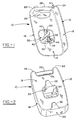
- a portable liquid dispenser made in accordance with the invention is designated generally by the numeral 10.
- the dispenser 10 comprises a housing or casing 12 which, in the preferred embodiment, comprises a unitary body, which is preferably blow molded of an appropriate plastic material.
- the dispenser 10 includes a front 14, a back 16, sides 18, and a bottom 20.
- a pair of ears 22, 24 extend above a trough 26, which is bridged by a handle 28.
- the entirety of the housing 12, including the handle 28, is hollow, comprising a container region that can be filled with the liquid to be dispensed.
- a bore 32 passes through a bottom wall of the walled aperture 30, and is configured to receive a pump 34 for pumping and dispensing the liquid to be contained within the portable liquid dispenser 10.
- the pump 34 may be any suitable pump, such as a liquid pump, foam pump, positive displacement pump, siphon pump, or the like.
- the pump 34 is sealed and non-vented, allowing the entirety of the hollow container defined by the housing 12 to be filled with liquid, without the pump leaking. In other words, the entirety of the hollow interior of the housing 12 will be filled with liquid, including the ears 22, 24 and the handle 28, which are positioned well above the pump.
- undercut detents 36, 38 which are, in the disclosed embodiment, of a truncated triangular or trapezoidal nature. These undercut detents are provided for hanging of the portable liquid dispenser upon an appropriate receptacle, such as a nail, screw head, or the like. Accordingly, the dispenser 10 may be readily received upon a vertical flat surface, such as a wall. Similarly, the bottom 20 of the portable dispenser 10 is flat, capable of being received upon a flat horizontal surface, such as a table or bench top, or the like.
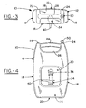
- the pump 34 includes a spout 40 from which the liquid is dispensed.
- a push or actuating surface 42 is provided for engagement by a user's hand or fingers, to depress the pump to achieve the desired dispensing action.
- a stem 44 extends from the actuating surface 42 and through a collar 46 into the interior of the housing 12.
- the pump 34 is configured to be totally contained within the walled aperture 30 to accommodate stacking and packaging of the portable dispensers 10 for shipment and the like. Further, it is desired that the pump 34 be so fully contained to prevent inadvertent actuation of the pump, which might otherwise occur if it extended beyond the confines of the walled aperture 30 during periods of non-use or transport. Accordingly, the stem 44 is provided with locking threads 48, readily understood by those skilled in the art, to provide a means for lockingly retaining the stem 44 and push surface 42 during such periods of time.
- Fig. 4 shows, in sold lines, the pump 34 in its down and locked position, totally confined within the walled aperture 30. The phantom depiction in Fig. 4 of the pump 34 shows its extended unlocked and operative position.
- this feature allows not only for safety during shipping, handling, carrying and the like, but also provides the dispenser 10 with a size and configuration that is fully retained within its footprint, and which is give to ease of packaging and shipping.
- the total mechanism of the invention including the housing 12, pump assembly 32, and fill and relief valve 50, to be discussed below, are of a sufficiently inexpensive nature to render the portable dispenser 10 disposable.
- a fill and relief valve 50 is provided at the uppermost portion of the housing 12 and, in the preferred embodiment, at the top of one of the ears, 24, 26.
- the fill and relief valve 50 is provided to allow for the filling of the hollow interior of the housing 12 with liquid, while allowing for the venting of air from the container during such filling.
- the fill and relief valve 50 accommodates the entry of air into the container during dispensing of liquid therefrom, to accommodate pressure equalization.
- the pump 34 may be a non-vented pump, not susceptible to leakage or the like.
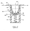
- the valve 50 includes a top collar 52, received about an aperture within an ear 24 of the housing 12.
- the valve 50 includes a cylindrical housing 54, with a plurality of upper apertures 56 circumferentially spaced about a top portion thereof.
- the apertures 56 serve as outlet or exhaust apertures, allowing for the exhausting of air during the filling operation.
- a plurality of lower apertures 58 are circumferentially spaced about a mid portion of the cylindrical housing 54, and serve the dual function of fill apertures for receipt of liquid having a fill operation and breather apertures for allowing the replenishment of air into the container during a dispensing operation.
- the cylindrical housing 54 is open as at a top opening 60, and receives therein an upper valve member 62, which includes an upper cylindrical portion 64 extending to a truncated conical portion 66.
- a lower valve member 68 comprises an upper conical portion 70 connected to a lower cylindrical portion 72. As shown, the respective conical portions 66, 70 of the valve members 62, 68 nestingly and sealingly engage.
- a spring 74 interposed between the base of the cylindrical housing 54 and the cylindrical portion 72 of the valve member 68 urges the valve member 68 upwardly into closing and sealing engagement with the valve member 62.
- a filler head 76 is provided in association with a reservoir of the liquid to be introduced into the interior cavity of the housing 12, and is provided with a body 78 having a cylindrical portion and a conical section to engage the upper seal member 62, as shown. Additionally, a cylindrical section 80 is provided on the filler head 76 to extend through the bottom opening of the conical portion 66 of the upper valve member 62, the cylindrical section 80 being configured to engage the lower valve member 68 and to separate it from the upper valve member 62, against the urging and biasing of the spring 74, as illustrated.
- a tubular fill member 82 is provided as a portion of the filler head assembly 76, 78 through which liquid may pass from a mass reservoir and into the cavity of the housing 12, as will be appreciated from reference to Fig. 6 .
- the conical portion 66 of the upper valve member 62 is configured to engage with a tapered shoulder 84 about the interior wall of the cylindrical housing 54. That engagement restricts downward movement of the upper valve member 62 against downward urging of the filler head assembly 76, 78.
- the lower valve member 68 separates from the upper valve member 62 against the urging of the spring 74, and breaks the seal between the upper and lower valve members 62, 68.
- the apertures 56 are open from the interior of the container housing 12 to the top opening 60 of the cylindrical housing 54. The path allows for the exhausting of air during the filling operation.
- the upper valve member 62 is sealed against the shoulder 84 about the inner perimeter of the cylindrical housing 54.
- the filler head assembly 76, 78 makes inner sealing engagement with the interior of the upper valve member 62.
- the lower valve member 68 is in engagement with the upper valve member 62, with the upper valve member 62 sealingly engaging the upper apertures 56.
- the housing 12 would have a tendency to collapse or otherwise deform.
- the vacuum created in the interior of the housing 12 is sufficient to slightly draw the lower valve member 68 away from the upper valve member 62, to allow air from the ambient to enter through the opening 60 and between the valve member 62, 68, and thence into the interior of the housing 12 along the path of the arrows 90. Accordingly, the integrity of the housing 12 remains.
- the fill and relief valve 50 might include a threaded top to receive a cap or the like, if desired.
- such sealing engagement is not necessary, since the spring biasing of the spring 74 keeps the aperture 56 in a normally sealed position, and keeps the upper and lower valve members 62, 68 in a normally sealed position, as well.
- a disposable portable liquid dispenser suitable for soaps, sanitizers, condiments, and various other liquids.
- the entirety of the interior of the blow molded housing for the dispenser is adapted to receive and retain the desired liquid.
- the unvented pump allows for dispensing of the liquid, while locking of the pump during periods of transport and non-use, and positioning of the spout in an unobtrusive manner accommodates a maximization of space utility during packaging and shipping.
- the fill and relief valve accommodates rapid filling of the interior of the dispenser with the desired liquid in an automated process, while also accommodating breathing of the interior of the dispenser to replace dispensed fluid with air.
Claims (18)
- Flüssigkeitsspender (10), umfassend:ein Gehäuse (12), das einen hohlen Behälter definiert;eine von Wänden umgebene Öffnung (30), die durch das Gehäuse (12) hindurch geht, gekennzeichnet durcheine Spenderpumpe (34), die innerhalb der von Wänden umgebenen Öffnung (30) aufgenommen ist und in den Behälter (12) hineinragt.
- Flüssigkeitsspender nach Anspruch 1, wobei die Spenderpumpe wahlweise vollständig innerhalb der von Wänden umgebenen Öffnung positionierbar ist.
- Flüssigkeitsspender nach Anspruch 2, wobei die Spenderpumpe einen Spenderabschnitt (40) aufweist, der wahlweise außerhalb der von Wänden umgebenen Öffnung positionierbar ist.
- Flüssigkeitsspender nach Anspruch 3, wobei die Spenderpumpe unbelüftet ist.
- Flüssigkeitsspender nach Anspruch 2, wobei die von Wänden umgebene Öffnung im Wesentlichen zentral innerhalb des Gehäuses positioniert ist.
- Flüssigkeitsspender nach Anspruch 1, wobei das Gehäuse einen Griff (28) an einem oberen Abschnitt des Gehäuses aufweist.
- Flüssigkeitsspender nach Anspruch 6, wobei das Gehäuse und der Griff als ein integrales, hohles Teil geformt sind.
- Flüssigkeitsspender nach Anspruch 7, wobei das Gehäuse einen flachen Boden (20) zur Aufnahme auf einer horizontalen Oberfläche aufweist.
- Flüssigkeitsspender nach Anspruch 1, weiter umfassend eine Lüftung an einem oberen Abschnitt des Gehäuses.
- Flüssigkeitsspender nach Anspruch 9, wobei die Lüftung ein kombiniertes Füll- und Entlastungsventil (50) umfasst, das das Füllen des hohlen Behälters mit Flüssigkeit und das Ablassen von Luft daraus bewerkstelligt.
- Flüssigkeitsspender nach Anspruch 10, wobei das Füll- und Entlastungsventil (50) umfasst:ein Füll- und Entlastungsventilgehäuse (54), das erste und zweite Öffnungen (56, 58) darin in Kommunikation mit einem Inneren des hohlen Behälters aufweist;ein erstes Ventilelement (64), das in dem Füll- und Entlastungsventilgehäuse aufgenommen ist;ein zweites Ventilelement (68), das in dem Füll- und Entlastungsventilgehäuse aufgenommen ist, wobei das erste und zweite Ventilelement wahlweise den Eintritt von Flüssigkeit und Luft in das Innere des hohlen Behälters und das Ablassen von Luft aus dem Inneren des hohlen Behälters bewerkstelligen.
- Flüssigkeitsspender nach Anspruch 11, wobei das erste Ventilelement wahlweise dichtend in das zweite Ventilelement (68) eingreift.
- Flüssigkeitsspender nach Anspruch 12, wobei das erste Ventilelement vorgespannt ist, normalerweise die erste Öffnung (56) abzudichten, und bewegbar ist, um die erste Öffnung zu öffnen.
- Flüssigkeitsspender nach Anspruch 13, wobei das erste und zweite Ventilelement zu einem abgedichteten Ineinandergreifen vorgespannt und aus dem abgedichteten Ineinandergreifen heraus trennbar bewegbar sind, um Flüssigkeit zu erlauben, dort hindurch und in den hohlen Behälter durch die zweite Öffnung (58) zu fließen.
- Flüssigkeitsspender nach Anspruch 14, wobei Luft in den hohlen Behälter zwischen einer Grenzfläche zwischen erstem und zweitem Ventilelement (68) und durch die zweite Öffnung (58) gesaugt wird.
- Flüssigkeitsspender nach Anspruch 11, wobei die erste der Öffnungen einen Luftdurchlass für das Ausströmen von Luft, wenn Flüssigkeit in das Innere des hohlen Behälters durch die zweite (58) der Öffnungen (56, 58) eingeführt wird, umfasst.
- Flüssigkeitsspender nach Anspruch 16, wobei das erste und zweite Ventilelement (68) trennbar sind, um den Durchlass von Luft von außerhalb des hohlen Behälters in das Innere des hohlen Behälters durch die zweiten Öffnungen (58) zu bewerkstelligen, wenn Flüssigkeit ausgegeben wird.
- Flüssigkeitsspender nach Anspruch 1, wobei das Gehäuse eine Montagebuchse auf der Rückseite des Gehäuses zum Eingreifen in ein Halteelement zum Positionieren des Spenders an einer vertikalen Oberfläche aufweist.
Applications Claiming Priority (1)
| Application Number | Priority Date | Filing Date | Title |
|---|---|---|---|
| US11/259,486 US7690537B2 (en) | 2005-10-27 | 2005-10-27 | Portable liquid dispenser |
Publications (2)
| Publication Number | Publication Date |
|---|---|
| EP1792661A1 EP1792661A1 (de) | 2007-06-06 |
| EP1792661B1 true EP1792661B1 (de) | 2008-08-06 |
Family
ID=37903613
Family Applications (1)
| Application Number | Title | Priority Date | Filing Date |
|---|---|---|---|
| EP06255394A Not-in-force EP1792661B1 (de) | 2005-10-27 | 2006-10-20 | Tragbarer Flüssigkeitsspender |
Country Status (15)
| Country | Link |
|---|---|
| US (1) | US7690537B2 (de) |
| EP (1) | EP1792661B1 (de) |
| JP (1) | JP4938413B2 (de) |
| KR (1) | KR101278779B1 (de) |
| CN (1) | CN101070136A (de) |
| AT (1) | ATE403500T1 (de) |
| AU (1) | AU2006230698B2 (de) |
| BR (1) | BRPI0604349A (de) |
| CA (1) | CA2564667A1 (de) |
| DE (1) | DE602006002092D1 (de) |
| ES (1) | ES2309925T3 (de) |
| HK (1) | HK1105605A1 (de) |
| MY (1) | MY147725A (de) |
| SG (1) | SG131902A1 (de) |
| TW (1) | TW200803782A (de) |
Families Citing this family (18)
| Publication number | Priority date | Publication date | Assignee | Title |
|---|---|---|---|---|
| US8038034B2 (en) * | 2008-10-03 | 2011-10-18 | Gojo Industries, Inc. | Fluid dispenser for personal use |
| US20120305668A1 (en) * | 2010-01-29 | 2012-12-06 | Andy Davis | Spray Bottle and Methods of Making and Using the Same |
| GB2482027A (en) * | 2010-07-16 | 2012-01-18 | Packaging Innovation Ltd | A Portable Handheld Liquid Dispenser |
| US11123153B2 (en) | 2012-09-17 | 2021-09-21 | Sage Products, Llc | Method and system for ensuring and tracking hand hygiene compliance |
| US10121149B2 (en) | 2012-09-17 | 2018-11-06 | Sage Products, Llc | Methods for ensuring and tracking hand hygiene compliance |
| FR2999960B1 (fr) * | 2012-12-20 | 2015-02-27 | Aptar France Sas | Distributeur de produit fluide rechargeable. |
| US10287154B2 (en) | 2014-02-28 | 2019-05-14 | Ayr Ltd. | Electronic vaporiser system |
| US10130119B2 (en) | 2014-02-28 | 2018-11-20 | Beyond Twenty Ltd. | Electronic vaporiser system |
| GB201413018D0 (en) * | 2014-02-28 | 2014-09-03 | Beyond Twenty Ltd | Beyond 1A |
| US11085550B2 (en) | 2014-02-28 | 2021-08-10 | Ayr Ltd. | Electronic vaporiser system |
| US10588176B2 (en) | 2014-02-28 | 2020-03-10 | Ayr Ltd. | Electronic vaporiser system |
| BR202014025378Y1 (pt) * | 2014-10-10 | 2018-04-17 | Acacio Da Silva Edilberto | Disposição construtiva introduzida em embalagem |
| WO2017037457A1 (en) | 2015-09-01 | 2017-03-09 | Beyond Twenty Limited | Electronic vaporiser system |
| CN108978132A (zh) * | 2018-09-27 | 2018-12-11 | 青岛海尔洗衣机有限公司 | 外置储液盒及家用电器 |
| DE202018106397U1 (de) * | 2018-11-12 | 2019-01-29 | Icon Guest Concepts & Supply Gmbh | Vorrichtung zur Abgabe eines Flüssigprodukts |
| CN113382708A (zh) * | 2019-01-29 | 2021-09-10 | 詹姆斯·M·瑞纳森 | 杂屑去除装置及方法 |
| USD919445S1 (en) * | 2019-05-03 | 2021-05-18 | Bo VanderWoude | Dispenser bottle |
| US20230213261A1 (en) * | 2022-01-05 | 2023-07-06 | Brumate, Inc. | Multi-function cooler |
Family Cites Families (19)
| Publication number | Priority date | Publication date | Assignee | Title |
|---|---|---|---|---|
| US2723056A (en) * | 1954-03-17 | 1955-11-08 | Alva T Smith | Dispensing container for liquids and an extensible and retractable discharge spout therefor |
| JPS515769Y2 (de) * | 1972-07-20 | 1976-02-18 | ||
| US3993251A (en) * | 1975-06-27 | 1976-11-23 | Garets Christian Des | Manual pressure sprayer |
| US4030664A (en) * | 1976-04-12 | 1977-06-21 | Custom Plastics, Inc. | Spraying and watering can |
| FR2545382B1 (fr) | 1983-05-04 | 1986-07-18 | Teleplastics Ind Sa | Vaporisateur de sac rechargeable |
| US4890767A (en) * | 1987-03-02 | 1990-01-02 | C & S Distributing Co. | Headband squirter |
| US4923098A (en) * | 1987-03-30 | 1990-05-08 | Schoonover Michael I | Fluid container |
| JPS6354637U (de) * | 1987-09-18 | 1988-04-12 | ||
| US4903864A (en) * | 1988-06-14 | 1990-02-27 | Sirhan Eddie A | Glove amusement device |
| US5056691A (en) * | 1990-05-21 | 1991-10-15 | Douglas Tolbert | Valved fuel dispensing container |
| JPH0435598U (de) * | 1990-07-20 | 1992-03-25 | ||
| DE69311769T2 (de) * | 1992-01-31 | 1998-01-29 | Contico Int Inc | Flüssigkeitsspendereinrichtung mit adapter |
| JPH0873879A (ja) * | 1994-08-31 | 1996-03-19 | Tonen Corp | 流体継手用流体組成物 |
| US6068163A (en) * | 1997-03-17 | 2000-05-30 | Kihm; Scott C. | Fuel dispensing apparatus |
| US6293692B1 (en) * | 1999-11-05 | 2001-09-25 | M. William Bowsher | Multipurpose container structure |
| FR2810646B1 (fr) * | 2000-06-23 | 2002-10-04 | Valois Sa | Distributeur de produit fluide a reservoir echancre |
| JP2002046746A (ja) | 2000-08-02 | 2002-02-12 | Kitto:Kk | ポリタンク |
| WO2003089311A2 (en) * | 2002-04-16 | 2003-10-30 | Andrew Durant | Applicator and integrated concentrate system |
| US7651009B2 (en) | 2004-08-16 | 2010-01-26 | Warner Lambert Company Llc | Liquid dispensing device |
-
2005
- 2005-10-27 US US11/259,486 patent/US7690537B2/en not_active Expired - Fee Related
-
2006
- 2006-10-17 TW TW095138231A patent/TW200803782A/zh unknown
- 2006-10-18 MY MYPI20064346A patent/MY147725A/en unknown
- 2006-10-19 CA CA002564667A patent/CA2564667A1/en not_active Abandoned
- 2006-10-20 AU AU2006230698A patent/AU2006230698B2/en not_active Ceased
- 2006-10-20 AT AT06255394T patent/ATE403500T1/de not_active IP Right Cessation
- 2006-10-20 DE DE602006002092T patent/DE602006002092D1/de not_active Expired - Fee Related
- 2006-10-20 EP EP06255394A patent/EP1792661B1/de not_active Not-in-force
- 2006-10-20 ES ES06255394T patent/ES2309925T3/es active Active
- 2006-10-25 BR BRPI0604349-6A patent/BRPI0604349A/pt not_active Application Discontinuation
- 2006-10-26 KR KR1020060104310A patent/KR101278779B1/ko not_active IP Right Cessation
- 2006-10-27 SG SG200607350-6A patent/SG131902A1/en unknown
- 2006-10-27 CN CNA2006101428680A patent/CN101070136A/zh active Pending
- 2006-10-27 JP JP2006292550A patent/JP4938413B2/ja not_active Expired - Fee Related
-
2007
- 2007-10-05 HK HK07110847.7A patent/HK1105605A1/xx not_active IP Right Cessation
Also Published As
| Publication number | Publication date |
|---|---|
| AU2006230698A1 (en) | 2007-05-17 |
| ATE403500T1 (de) | 2008-08-15 |
| TW200803782A (en) | 2008-01-16 |
| JP4938413B2 (ja) | 2012-05-23 |
| JP2007119069A (ja) | 2007-05-17 |
| HK1105605A1 (en) | 2008-02-22 |
| KR20070045941A (ko) | 2007-05-02 |
| KR101278779B1 (ko) | 2013-06-25 |
| US20070095861A1 (en) | 2007-05-03 |
| EP1792661A1 (de) | 2007-06-06 |
| MY147725A (en) | 2013-01-15 |
| ES2309925T3 (es) | 2008-12-16 |
| SG131902A1 (en) | 2007-05-28 |
| CA2564667A1 (en) | 2007-04-27 |
| AU2006230698B2 (en) | 2011-12-22 |
| BRPI0604349A (pt) | 2007-08-21 |
| US7690537B2 (en) | 2010-04-06 |
| DE602006002092D1 (de) | 2008-09-18 |
| CN101070136A (zh) | 2007-11-14 |
Similar Documents
| Publication | Publication Date | Title |
|---|---|---|
| EP1792661B1 (de) | Tragbarer Flüssigkeitsspender | |
| JP2007119069A5 (de) | ||
| EP3083443B1 (de) | Deckel mit faltbarem trinkhalm für eine flasche | |
| US8113239B2 (en) | Vented valve assembly | |
| US6533145B2 (en) | Self-contained viscous liquid dispenser | |
| US8336740B1 (en) | Fluid dispenser and pump adapter system therefor | |
| JP4338871B2 (ja) | 液体用壁掛けディスペンサー | |
| EP2209558B1 (de) | Spendervorrichtung für flüssigkeit | |
| JP5158705B2 (ja) | 液体噴出器 | |
| CA2613929A1 (en) | Closure for can filler port and can vent | |
| JP4171822B2 (ja) | 液体を収容した軟質容器に被着する外容器 | |
| WO2020201453A1 (en) | Down-locked pump with chaplet vent and beaded seal | |
| CN215687335U (zh) | 一种自动出液装置的容器、给皂装置及储物柜 | |
| KR101101288B1 (ko) | 유체 흡입수단을 구비하는 유체 저장용기 | |
| KR200383087Y1 (ko) | 디스펜서 용기 | |
| JP2023125489A (ja) | 泡吐出容器 | |
| JP2558027Y2 (ja) | 液体注出容器 | |
| JP2018203287A (ja) | 包装容器 | |
| JPH0740515U (ja) | 詰め替え式注出容器 |
Legal Events
| Date | Code | Title | Description |
|---|---|---|---|
| PUAI | Public reference made under article 153(3) epc to a published international application that has entered the european phase |
Free format text: ORIGINAL CODE: 0009012 |
|
| AK | Designated contracting states |
Kind code of ref document: A1 Designated state(s): AT BE BG CH CY CZ DE DK EE ES FI FR GB GR HU IE IS IT LI LT LU LV MC NL PL PT RO SE SI SK TR |
|
| AX | Request for extension of the european patent |
Extension state: AL BA HR MK YU |
|
| 17P | Request for examination filed |
Effective date: 20071112 |
|
| AKX | Designation fees paid |
Designated state(s): AT BE BG CH CY CZ DE DK EE ES FI FR GB GR HU IE IS IT LI LT LU LV MC NL PL PT RO SE SI SK TR |
|
| REG | Reference to a national code |
Ref country code: HK Ref legal event code: DE Ref document number: 1105605 Country of ref document: HK |
|
| GRAP | Despatch of communication of intention to grant a patent |
Free format text: ORIGINAL CODE: EPIDOSNIGR1 |
|
| RIN1 | Information on inventor provided before grant (corrected) |
Inventor name: YATES, JAMES M. Inventor name: QUINLAN, ROBERT L. Inventor name: SPRIEGEL, ANDREW R. |
|
| GRAS | Grant fee paid |
Free format text: ORIGINAL CODE: EPIDOSNIGR3 |
|
| GRAA | (expected) grant |
Free format text: ORIGINAL CODE: 0009210 |
|
| AK | Designated contracting states |
Kind code of ref document: B1 Designated state(s): AT BE BG CH CY CZ DE DK EE ES FI FR GB GR HU IE IS IT LI LT LU LV MC NL PL PT RO SE SI SK TR |
|
| REG | Reference to a national code |
Ref country code: GB Ref legal event code: FG4D |
|
| REG | Reference to a national code |
Ref country code: CH Ref legal event code: EP |
|
| REG | Reference to a national code |
Ref country code: IE Ref legal event code: FG4D |
|
| REF | Corresponds to: |
Ref document number: 602006002092 Country of ref document: DE Date of ref document: 20080918 Kind code of ref document: P |
|
| PGFP | Annual fee paid to national office [announced via postgrant information from national office to epo] |
Ref country code: IE Payment date: 20080825 Year of fee payment: 3 |
|
| REG | Reference to a national code |
Ref country code: ES Ref legal event code: FG2A Ref document number: 2309925 Country of ref document: ES Kind code of ref document: T3 |
|
| PG25 | Lapsed in a contracting state [announced via postgrant information from national office to epo] |
Ref country code: LT Free format text: LAPSE BECAUSE OF FAILURE TO SUBMIT A TRANSLATION OF THE DESCRIPTION OR TO PAY THE FEE WITHIN THE PRESCRIBED TIME-LIMIT Effective date: 20080806 Ref country code: IS Free format text: LAPSE BECAUSE OF FAILURE TO SUBMIT A TRANSLATION OF THE DESCRIPTION OR TO PAY THE FEE WITHIN THE PRESCRIBED TIME-LIMIT Effective date: 20081206 |
|
| PG25 | Lapsed in a contracting state [announced via postgrant information from national office to epo] |
Ref country code: SI Free format text: LAPSE BECAUSE OF FAILURE TO SUBMIT A TRANSLATION OF THE DESCRIPTION OR TO PAY THE FEE WITHIN THE PRESCRIBED TIME-LIMIT Effective date: 20080806 Ref country code: LV Free format text: LAPSE BECAUSE OF FAILURE TO SUBMIT A TRANSLATION OF THE DESCRIPTION OR TO PAY THE FEE WITHIN THE PRESCRIBED TIME-LIMIT Effective date: 20080806 Ref country code: FI Free format text: LAPSE BECAUSE OF FAILURE TO SUBMIT A TRANSLATION OF THE DESCRIPTION OR TO PAY THE FEE WITHIN THE PRESCRIBED TIME-LIMIT Effective date: 20080806 Ref country code: AT Free format text: LAPSE BECAUSE OF FAILURE TO SUBMIT A TRANSLATION OF THE DESCRIPTION OR TO PAY THE FEE WITHIN THE PRESCRIBED TIME-LIMIT Effective date: 20080806 |
|
| PGFP | Annual fee paid to national office [announced via postgrant information from national office to epo] |
Ref country code: ES Payment date: 20081001 Year of fee payment: 3 |
|
| PGFP | Annual fee paid to national office [announced via postgrant information from national office to epo] |
Ref country code: BE Payment date: 20081028 Year of fee payment: 3 |
|
| PG25 | Lapsed in a contracting state [announced via postgrant information from national office to epo] |
Ref country code: BG Free format text: LAPSE BECAUSE OF FAILURE TO SUBMIT A TRANSLATION OF THE DESCRIPTION OR TO PAY THE FEE WITHIN THE PRESCRIBED TIME-LIMIT Effective date: 20081106 Ref country code: DK Free format text: LAPSE BECAUSE OF FAILURE TO SUBMIT A TRANSLATION OF THE DESCRIPTION OR TO PAY THE FEE WITHIN THE PRESCRIBED TIME-LIMIT Effective date: 20080806 |
|
| PGFP | Annual fee paid to national office [announced via postgrant information from national office to epo] |
Ref country code: FR Payment date: 20081029 Year of fee payment: 3 |
|
| REG | Reference to a national code |
Ref country code: HK Ref legal event code: GR Ref document number: 1105605 Country of ref document: HK |
|
| PG25 | Lapsed in a contracting state [announced via postgrant information from national office to epo] |
Ref country code: PT Free format text: LAPSE BECAUSE OF FAILURE TO SUBMIT A TRANSLATION OF THE DESCRIPTION OR TO PAY THE FEE WITHIN THE PRESCRIBED TIME-LIMIT Effective date: 20090106 Ref country code: SK Free format text: LAPSE BECAUSE OF FAILURE TO SUBMIT A TRANSLATION OF THE DESCRIPTION OR TO PAY THE FEE WITHIN THE PRESCRIBED TIME-LIMIT Effective date: 20080806 Ref country code: RO Free format text: LAPSE BECAUSE OF FAILURE TO SUBMIT A TRANSLATION OF THE DESCRIPTION OR TO PAY THE FEE WITHIN THE PRESCRIBED TIME-LIMIT Effective date: 20080806 Ref country code: CZ Free format text: LAPSE BECAUSE OF FAILURE TO SUBMIT A TRANSLATION OF THE DESCRIPTION OR TO PAY THE FEE WITHIN THE PRESCRIBED TIME-LIMIT Effective date: 20080806 Ref country code: MC Free format text: LAPSE BECAUSE OF NON-PAYMENT OF DUE FEES Effective date: 20081031 |
|
| PGFP | Annual fee paid to national office [announced via postgrant information from national office to epo] |
Ref country code: DE Payment date: 20081219 Year of fee payment: 3 |
|
| PLBE | No opposition filed within time limit |
Free format text: ORIGINAL CODE: 0009261 |
|
| STAA | Information on the status of an ep patent application or granted ep patent |
Free format text: STATUS: NO OPPOSITION FILED WITHIN TIME LIMIT |
|
| 26N | No opposition filed |
Effective date: 20090507 |
|
| PG25 | Lapsed in a contracting state [announced via postgrant information from national office to epo] |
Ref country code: EE Free format text: LAPSE BECAUSE OF FAILURE TO SUBMIT A TRANSLATION OF THE DESCRIPTION OR TO PAY THE FEE WITHIN THE PRESCRIBED TIME-LIMIT Effective date: 20080806 |
|
| PG25 | Lapsed in a contracting state [announced via postgrant information from national office to epo] |
Ref country code: SE Free format text: LAPSE BECAUSE OF FAILURE TO SUBMIT A TRANSLATION OF THE DESCRIPTION OR TO PAY THE FEE WITHIN THE PRESCRIBED TIME-LIMIT Effective date: 20081106 |
|
| BERE | Be: lapsed |
Owner name: KANFER, JOSEPH S. Effective date: 20091031 |
|
| PGFP | Annual fee paid to national office [announced via postgrant information from national office to epo] |
Ref country code: IT Payment date: 20091031 Year of fee payment: 4 |
|
| REG | Reference to a national code |
Ref country code: NL Ref legal event code: V1 Effective date: 20100501 |
|
| PG25 | Lapsed in a contracting state [announced via postgrant information from national office to epo] |
Ref country code: PL Free format text: LAPSE BECAUSE OF FAILURE TO SUBMIT A TRANSLATION OF THE DESCRIPTION OR TO PAY THE FEE WITHIN THE PRESCRIBED TIME-LIMIT Effective date: 20080806 |
|
| REG | Reference to a national code |
Ref country code: FR Ref legal event code: ST Effective date: 20100630 |
|
| PG25 | Lapsed in a contracting state [announced via postgrant information from national office to epo] |
Ref country code: CY Free format text: LAPSE BECAUSE OF FAILURE TO SUBMIT A TRANSLATION OF THE DESCRIPTION OR TO PAY THE FEE WITHIN THE PRESCRIBED TIME-LIMIT Effective date: 20080806 Ref country code: DE Free format text: LAPSE BECAUSE OF NON-PAYMENT OF DUE FEES Effective date: 20100501 Ref country code: HU Free format text: LAPSE BECAUSE OF FAILURE TO SUBMIT A TRANSLATION OF THE DESCRIPTION OR TO PAY THE FEE WITHIN THE PRESCRIBED TIME-LIMIT Effective date: 20090207 Ref country code: FR Free format text: LAPSE BECAUSE OF NON-PAYMENT OF DUE FEES Effective date: 20091102 Ref country code: LU Free format text: LAPSE BECAUSE OF NON-PAYMENT OF DUE FEES Effective date: 20081020 Ref country code: NL Free format text: LAPSE BECAUSE OF NON-PAYMENT OF DUE FEES Effective date: 20100501 |
|
| PG25 | Lapsed in a contracting state [announced via postgrant information from national office to epo] |
Ref country code: TR Free format text: LAPSE BECAUSE OF FAILURE TO SUBMIT A TRANSLATION OF THE DESCRIPTION OR TO PAY THE FEE WITHIN THE PRESCRIBED TIME-LIMIT Effective date: 20080806 |
|
| PG25 | Lapsed in a contracting state [announced via postgrant information from national office to epo] |
Ref country code: GR Free format text: LAPSE BECAUSE OF FAILURE TO SUBMIT A TRANSLATION OF THE DESCRIPTION OR TO PAY THE FEE WITHIN THE PRESCRIBED TIME-LIMIT Effective date: 20081107 Ref country code: IE Free format text: LAPSE BECAUSE OF NON-PAYMENT OF DUE FEES Effective date: 20091020 Ref country code: BE Free format text: LAPSE BECAUSE OF NON-PAYMENT OF DUE FEES Effective date: 20091031 |
|
| REG | Reference to a national code |
Ref country code: ES Ref legal event code: FD2A Effective date: 20110302 |
|
| REG | Reference to a national code |
Ref country code: CH Ref legal event code: PL |
|
| GBPC | Gb: european patent ceased through non-payment of renewal fee |
Effective date: 20101020 |
|
| PG25 | Lapsed in a contracting state [announced via postgrant information from national office to epo] |
Ref country code: LI Free format text: LAPSE BECAUSE OF NON-PAYMENT OF DUE FEES Effective date: 20101031 Ref country code: ES Free format text: LAPSE BECAUSE OF NON-PAYMENT OF DUE FEES Effective date: 20110301 Ref country code: CH Free format text: LAPSE BECAUSE OF NON-PAYMENT OF DUE FEES Effective date: 20101031 |
|
| PG25 | Lapsed in a contracting state [announced via postgrant information from national office to epo] |
Ref country code: GB Free format text: LAPSE BECAUSE OF NON-PAYMENT OF DUE FEES Effective date: 20101020 |
|
| PG25 | Lapsed in a contracting state [announced via postgrant information from national office to epo] |
Ref country code: ES Free format text: LAPSE BECAUSE OF NON-PAYMENT OF DUE FEES Effective date: 20091021 |
|
| PG25 | Lapsed in a contracting state [announced via postgrant information from national office to epo] |
Ref country code: IT Free format text: LAPSE BECAUSE OF NON-PAYMENT OF DUE FEES Effective date: 20101020 |