EP1790933B1 - Concentric tubes, in particular for a heat exchanger - Google Patents
Concentric tubes, in particular for a heat exchanger Download PDFInfo
- Publication number
- EP1790933B1 EP1790933B1 EP20060022999 EP06022999A EP1790933B1 EP 1790933 B1 EP1790933 B1 EP 1790933B1 EP 20060022999 EP20060022999 EP 20060022999 EP 06022999 A EP06022999 A EP 06022999A EP 1790933 B1 EP1790933 B1 EP 1790933B1
- Authority
- EP
- European Patent Office
- Prior art keywords
- tube
- concentric
- concentric tube
- tube according
- fins
- Prior art date
- Legal status (The legal status is an assumption and is not a legal conclusion. Google has not performed a legal analysis and makes no representation as to the accuracy of the status listed.)
- Expired - Fee Related
Links
Images


Classifications
-
- F—MECHANICAL ENGINEERING; LIGHTING; HEATING; WEAPONS; BLASTING
- F28—HEAT EXCHANGE IN GENERAL
- F28D—HEAT-EXCHANGE APPARATUS, NOT PROVIDED FOR IN ANOTHER SUBCLASS, IN WHICH THE HEAT-EXCHANGE MEDIA DO NOT COME INTO DIRECT CONTACT
- F28D7/00—Heat-exchange apparatus having stationary tubular conduit assemblies for both heat-exchange media, the media being in contact with different sides of a conduit wall
- F28D7/10—Heat-exchange apparatus having stationary tubular conduit assemblies for both heat-exchange media, the media being in contact with different sides of a conduit wall the conduits being arranged one within the other, e.g. concentrically
- F28D7/106—Heat-exchange apparatus having stationary tubular conduit assemblies for both heat-exchange media, the media being in contact with different sides of a conduit wall the conduits being arranged one within the other, e.g. concentrically consisting of two coaxial conduits or modules of two coaxial conduits
-
- F—MECHANICAL ENGINEERING; LIGHTING; HEATING; WEAPONS; BLASTING
- F28—HEAT EXCHANGE IN GENERAL
- F28F—DETAILS OF HEAT-EXCHANGE AND HEAT-TRANSFER APPARATUS, OF GENERAL APPLICATION
- F28F1/00—Tubular elements; Assemblies of tubular elements
- F28F1/10—Tubular elements and assemblies thereof with means for increasing heat-transfer area, e.g. with fins, with projections, with recesses
- F28F1/40—Tubular elements and assemblies thereof with means for increasing heat-transfer area, e.g. with fins, with projections, with recesses the means being only inside the tubular element
-
- F—MECHANICAL ENGINEERING; LIGHTING; HEATING; WEAPONS; BLASTING
- F28—HEAT EXCHANGE IN GENERAL
- F28F—DETAILS OF HEAT-EXCHANGE AND HEAT-TRANSFER APPARATUS, OF GENERAL APPLICATION
- F28F13/00—Arrangements for modifying heat-transfer, e.g. increasing, decreasing
- F28F13/06—Arrangements for modifying heat-transfer, e.g. increasing, decreasing by affecting the pattern of flow of the heat-exchange media
- F28F13/12—Arrangements for modifying heat-transfer, e.g. increasing, decreasing by affecting the pattern of flow of the heat-exchange media by creating turbulence, e.g. by stirring, by increasing the force of circulation
Definitions
- the invention relates to a coaxial tube or a tube-in-tube arrangement according to the preamble of claim 1.
- EP-A1-0550845 shows such a coaxial tube.
- From the EP 1 202 016 A2 is a one-piece heat exchanger tube with a multi-chamber profile known, according to which a plurality of outer channels are provided around a central channel.
- the outer channels are divided by intermediate walls which extend in the radial direction.
- wave-like projections are provided, which extend slightly into the central channel. These projections serve to reduce the cross-sectional area and thus increase the flow velocity.
- the projections may also be helical, wherein constant, changing or changing slopes may be provided.
- the inner channel is used in this heat exchanger tube as the high pressure side, the outer channels as the low pressure side.
- a coaxial tube or a tube-in-tube arrangement for the separate line of at least two media, which is preferably refrigerant, wherein at least one and in a cross-sectional area in the coaxial tube or the tube-in-tube arrangement
- at most sixteen, more preferably at most twelve turbulence generators are provided, which are arranged in the inner region of the inner tube. The turbulence generators cause the boundary layer on the wall of the inner tube to be disturbed and thereby reduced, whereby the heat exchange and thereby the performance of the heat exchanger is improved.
- the turbulence generators are preferably arranged in the high-pressure region, which is usually provided in the inner region. However, it is also a twisted arrangement of high and low pressure area possible, i. the low pressure area is inside, the high pressure area outside.
- pipe is to be interpreted in the following very broad and refers not only to round cross-sections, but in particular also oval, rounded rectangular or any other cross-sections.
- the pipe may also be two tubes arranged inside one another which have no direct connections (tube-in-tube arrangement).
- positioning elements for the inner tube may be provided in the outer tube, such as provided on the outer and / or inner tube, radially inwardly or outwardly projecting ribs to optionally ensure a coaxial arrangement.
- the arrangement of the inner tube or of the inner region in the outer tube is preferably coaxial, but does not have to be, so that eccentric arrangements are also possible.
- several inner tubes may be provided, which are connected by means of several sleeves.
- the inner tube may also be soldered or otherwise connected to the outer tube in the contact regions.
- the turbulence generator is preferably formed by a helix extending in the longitudinal direction of the coaxial tube or the tube-in-tube arrangement.
- the helix is particularly preferably a round tube helix, wherein a gap is provided between the helix and the inner wall.
- the difference of the inner diameter of the inner tube and the coil width is preferably 0.2 to 1 mm, so that the coil does not jam in the event of bending of the tube.
- the helix preferably does not extend over the entire length of the tube but is in particular about 20 mm shorter, but is preferably at least about half as long as the tube, minus about 20 mm.
- the pitch of the helix is preferably 15 to 40 mm.
- At least one, in particular at least four, and a maximum of twelve inner ribs may be provided in the inner tube, alternatively or with a corresponding design, also in conjunction with a helix.
- the inner ribs may extend in the radial direction to the central longitudinal axis, but they may also be designed to extend obliquely to the radial direction.
- the inner ribs preferably have a rib thickness of 0.1 to 0.2 mm, so they are thin compared to the other wall thicknesses of the tube educated.
- the rib height of the inner ribs is preferably 0.5 to 1.5 mm with an inner diameter of the inner tube of 4 to 8 mm.
- the inner ribs are preferably arranged distributed in equidistant intervals over the inner circumference of the inner tube. However, it is also an uneven distribution, as well as a different rib height, possible.
- a turbulence generator is also at least one, in particular two or three webs in the inner tube in question. Of course, in particular four, five, six, seven, eight, nine or ten bars are conceivable.
- the web can in this case be designed to extend in the radial direction, as well as in any other way (i.e., as another tendon). If a plurality of webs are provided, they may preferably intersect in the longitudinal center axis of the pipe and subdivide the inner area into a plurality of subregions, wherein overflow openings may also be provided in the webs.
- the at least one web preferably has a web thickness of 0.2 to 0.6 mm, so it is preferably thinner than the outer and inner wall of the tube.
- the outer diameter of the outer tube is preferably 10 to 20 mm, in particular 12 to 18 mm.
- the inner diameter of the inner tube is preferably 3 to 10 mm, in particular 4 to 8 mm.
- the thickness of ribs or webs between the inner and outer tubes is preferably 0.3 to 1.1 mm, in particular 0.5 to 1.0 mm.
- the inlet openings of the two media are arranged on different sides of the coaxial tube or the tube-in-tube arrangement, so that the coaxial tube or the tube-in-tube arrangement is flowed through in countercurrent operation.
- the outer region, in which preferably the low-pressure medium flows, is preferably in at least six, in particular at least eight sub-channels and a maximum of twenty, preferably divided into a maximum of sixteen sub-channels.
- the wall thickness of the outer wall is preferably greater than or equal to the wall thickness of the wall between the outer tube and the inner tube.
- the wall thickness of the outer wall is preferably 0.6 to 1.3 mm, in particular 0.8 to 1.1 mm, the inner wall 0.6 to 1.2 mm, preferably 0.8 to 1.0 mm
- the thickness of the ribs or webs, which divide the individual sub-channels of the outer tube, is preferably less than or equal to the wall thickness of the wall of the outer tube.
- the web width is preferably 0.5 to 1.0 mm, wherein the wall thickness of the outer wall is 0.6 to 1.3 mm.
- At least one of the turbulence generators and / or at least one of the inner ribs and / or at least one of the webs, and / or at least one of the ribs between the inner and outer tubes is preferably arranged obliquely with respect to the tube longitudinal axis.
- the slope can also change over the total length of the tube, as well as the direction of rotation.
- At least one of the turbulence generators and / or at least one of the inner ribs and / or at least one of the webs and / or at least one of the ribs between the inner and outer tubes is formed obliquely with respect to the tube longitudinal axis with such a pitch that a 360 ° rotation over a tube length of 15 to 35 mm, in particular from 20 to 25 mm, takes place.
- the length of at least one of the turbulence generators and / or at least one of the inner ribs and / or at least one of the webs and / or at least one of the ribs between inner and outer tube 0.3 times to 0, 5 times, preferably equal to 0.4 times the tube length. It is also conceivable, however, for the length of at least one of the aforementioned devices to correspond essentially to the tube length.
- a coaxial tube or a tube-in-tube arrangement is provided for the separate line of at least two media, the pressure level of which differs, with the coaxial tube or the tube-in-tube arrangement the low-pressure side in the radial direction closer to the central longitudinal axis than the high pressure side is arranged.
- the twisted arrangement, the inner tube may be formed with a smaller wall thickness, which reduces the total weight, the material requirements and thus the cost of the coaxial tube or the tube-in-tube arrangement.
- the dimensions can be slightly reduced, which also reduces the heat input from the outside into the system and thus the performance can be increased.
- the free flow cross section of the high pressure side is preferably smaller overall than the free flow cross section of the low pressure side.
- the free flow cross sections differ such that the free flow cross section of the high pressure side is preferably at most half as large and preferably at least a quarter as large, more preferably about one third +/- 10% is as large as the free flow cross section of the low pressure side.
- the outer diameter of the outer tube is - with twisted arrangement of high and low pressure side - preferably 10 to 18 mm, in particular 12 to 16 mm.
- the inner diameter of the inner tube is preferably 6 to 12 mm, in particular 8 to 10 mm.
- the width of the ribs between the inner and outer tubes is preferably 0.3 to 0.8 mm, particularly preferably 0.4 to 0.7 mm.
- the outer tube is - in the twisted arrangement of high and low pressure side - preferably divided into at least six, in particular at least ten, more preferably at least twelve sub-channels and a maximum of twenty, preferably a maximum of sixteen sub-channels. This subdivision allows optimal strength properties of the pipe, connected with a large heat transfer area for the medium flowing in the outer area.
- the wall thickness of the outer wall is in the twisted arrangement of high and low pressure side - preferably larger than the wall thickness of the wall between the outer tube and the inner tube. Due to the greater pressure difference from the outer tube to the environment than from the outer tube to the inner region, the wall thickness to the inner tube can be made smaller, so that a material saving is possible. Is - as in conventional coaxial tubes - the maximum pressure in the inner tube provided, the outer tube, however, must also be able to withstand the corresponding pressure, which is why it should have a corresponding wall thickness and therefore designed in conventional coaxial tubes according to the inner tube, making the coaxial tube heavier and thus more expensive than a coaxial tube according to the invention. Incidentally, an improvement in the heat transfer performance can be achieved by the thinner wall.
- the width of the ribs or webs, which divide the individual sub-channels of the outer tube, is preferably smaller than the wall thickness of the wall of the outer tube, which can also save material.
- the width of the webs, which divide the individual sub-channels of the outer tube greater than or equal to the wall thickness of the wall between the outer tube and the inner tube.
- the inflow of the corresponding medium preferably takes place substantially coaxially, for which purpose the corresponding connecting piece is designed accordingly.
- a coaxial tube according to the invention or a tube-in-tube arrangement according to the invention can be used in particular for heat exchangers, preferably for motor vehicle air conditioners, particularly preferably for high-pressure air conditioning systems (such as in R744 air conditioners) of motor vehicles, however, other applications are also possible.
- heat exchangers preferably for motor vehicle air conditioners, particularly preferably for high-pressure air conditioning systems (such as in R744 air conditioners) of motor vehicles, however, other applications are also possible.
- the use as a so-called inner heat exchanger or internal heat exchanger is especially preferred.
- the refrigerant used usually behaves, even if it is at least partially in the gaseous state, due to the usually very high density similar to a fluid. In particular, this makes it possible, for example by using a turbulence generator to increase the heat transfer between the channels
- the proposed application of high pressure on the outside or low pressure on the inside may prove to be particularly advantageous.
- the high pressure usually has a higher temperature than the low pressure, so that particularly good additional heat energy can be dissipated from the high-pressure side refrigerant to the environment.
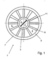
- a heat exchanger 1 of which only a cross section in the FIGS. 1 and 3 is shown, but may be formed in principle, as in Fig. 2 is shown with an enlarged, shown another cross-section provided.
- This heat exchanger 1 serves the heat exchange of a first medium and a second medium.
- the first medium flows through the inner region 2 of an inner tube 3 and the second medium through the outer region 4 which is formed between an outer tube 5 and the inner tube 3.
- the inner tube 3 and the outer tube 5 together with them in the radial direction in the longitudinal direction continuously extending ribs 6 are integrally extruded as a coaxial tube 7 made of an aluminum alloy.
- the outer diameter of the coaxial tube 7 is present 16 mm, the wall thickness of the outer tube 5 0.8 mm, the wall thickness of the inner tube 3 0.6 mm, the rib width 0.7 mm and the inner diameter 7 mm.
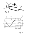
- 7 connecting components 8 are at both ends of the coaxial tube (see Fig. 2 ), via which the media, which in the present case flow in countercurrent operation through the inner region 2 or the outer region 4, are supplied or discharged separately from one another.
- coaxially extruded coaxial tube 7 On coaxially extruded coaxial tube 7 is located on the outer tube 5 (high pressure side) a higher pressure p a than on the inner tube 3 (low pressure side) to which the pressure p i is applied.
- the operating pressure on the low pressure side is according to the present embodiment about 130 bar, the corresponding bursting pressure 264 bar, and the operating pressure on the high pressure side is about 160 bar, the corresponding bursting pressure 352 bar.
- the mentioned pressure values refer in particular to the use of CO 2 (R744) as refrigerant.
- an improved, defined flow of the high-pressure refrigerant can be realized via the corresponding connecting piece 8, in particular, as in the present case Fig. 3 shown, a deflection-free flow of the high-pressure refrigerant provided in the direction of the longitudinal axis of the inner tube, whereby the pressure loss can be reduced and thereby the cooling capacity can be improved.
- the flow of the low-pressure refrigerant takes place in the radial direction with respect to the longitudinal axis of the coaxial tube. 1
- a turbulence generator 11 in the form of a helix (round tube helix) is provided which can be bent in the coaxial tube and bent with the same.
- the pitch of the helix in this case corresponds to a multiple of the inner diameter of the inner tube 3 and is constant over the entire Koaxialrohronne.
- the helix deflects the refrigerant flowing in the inner tube, so that no laminar flow is formed in the wall region, resulting in improved mixing and improved heat exchange.
- the pitch of the helix changes over the length of the coaxial tube and / or changes the direction of rotation of the helix, whereby multiple changes can be made.
- Fig. 4 shows a second embodiment which - unless mentioned below - corresponds to the first embodiment, but has no helix as a turbulence generator 11.
- the second embodiment are rather uniform over the inner circumference of the inner tube 3 distributed as a turbulence generator 11 eight inner ribs 21 provided in the radial direction inwardly projecting.
- the inner ribs have a rib thickness which is 0.1 mm less than the wall thickness of the outer tube 5.
- the length of the inner ribs 21 is presently 1 mm, so that they leave a circle of 5 mm diameter in the middle of the inner tube 3 free.
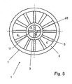
- Fig. 5 illustrated embodiment which, unless mentioned below - corresponds to the first embodiment, but has no coil as a turbulence generator 11, looks as a turbulence generator 11, two perpendicular crossing webs 22 in the inner tube 3, which quadrant the inner region 2.
- the web thickness is 0.1 mm less than the wall thickness of the outer tube 5.
- a coaxial tube 7 with a helix as a turbulence generator 11 which has different dimensions than the coaxial tube 7 of the first embodiment.
- a heat exchanger 1 of which only one cross section in Fig. 6 is shown, but may be formed in principle, as in Fig. 2 is shown with an enlarged, shown another cross-section provided.
- This heat exchange 1 serves heat exchange of a first medium and a second medium.
- the first medium flows through the inner region 2 of an inner tube 3 and the second medium through the outer region 4 which is formed between an outer tube 5 and the inner tube 3.
- the inner tube 3 and the outer tube 5 together with them in the radial direction in the longitudinal direction continuously extending ribs 6 are integrally extruded as a coaxial tube 7 made of an aluminum alloy.
- the outer diameter of the coaxial tube 7 is present 16 mm, the wall thickness of the outer tube 5 0.8 mm, the wall thickness of the inner tube 3 0.6 mm, the rib width 0.7 mm and the inner diameter 11 mm.
- the free cross-sectional area of the inner tube 3 is about 95 mm 2
- the sum of the free cross-sectional areas of the outer channels is about 35 mm 2 , that is about 60% smaller than that of the inner tube. 3
- a turbulence generator 11 in the form of a helix (round tube helix) is provided, which can be arranged in the coaxial tube bend with the same.
- the pitch of the helix in this case corresponds approximately to twice the inner diameter of the inner tube 3, ie about 22 mm, and is constant over the entire Koaxialrohronne.
- the helix deflects the refrigerant flowing in the inner tube, so that no laminar flow is formed in the wall region, resulting in improved mixing and improved heat exchange.
- 7 connecting components 8 are at both ends of the coaxial tube (see Fig. 2 ), via which the media, which in the present case flow in countercurrent operation through the inner region 2 or the outer region 4, are supplied or discharged separately from one another.
- a higher pressure is applied to the outer tube 5 (high pressure side) than to the inner tube 3 (low pressure side).
- the operating pressure on the low pressure side is according to the present embodiment about 130 bar, the corresponding bursting pressure 264 bar, and the operating pressure on the high pressure side is about 160 bar, the corresponding bursting pressure 352 bar.
- the mentioned pressure values refer in particular to the use of CO 2 (R744) as refrigerant.
- an improved flow of the low-pressure chaff agent can be realized via the corresponding connection piece 8, in particular, as in the present case Fig. 3 shown, a deflection-free flow of the low-pressure refrigerant provided in the direction of the longitudinal axis of the inner tube, whereby the pressure loss is reduced and thereby the cooling capacity can be improved.
- the Flow of the high-pressure refrigerant takes place in the radial direction with respect to the longitudinal axis of the coaxial tube. 1
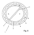
- Fig. 7 shows a fifth embodiment of a coaxial tube, wherein in the inner tube 3 as turbulence generator 11 both four evenly distributed over the circumference inner ribs 21 are provided with a length of about half the radius and two perpendicular to each other and at a gap to the inner ribs 21 webs 22 which the Divide the interior into four separate areas. Otherwise, the coaxial tube 7 corresponds to that of the fourth embodiment, however, a corresponding embodiment of the turbulence generator 11 is also possible to the previously described form. These internals in the inner tube 3 increase the heat transfer area and therefore improve the heat exchange.
- the coaxial tube is extruded rotated, i. the ribs, inner ribs and webs run helically, in this case with a constant pitch.
- the coaxial tube is in turn rotated extruded, but changed with changing rotational speed, so that the pitch of the ribs, inner ribs and webs changed over the length of the coaxial tube.
- two tendons are provided opposite one another in the inner tube of the coaxial tube instead of the webs extending in the radial direction.
- a not shown in the drawing sixth embodiment provides a tube-in-tube arrangement as a coaxial tube, wherein the outer tube ribs and the inner tube as a turbulence generator inner ribs and webs, and the outer tube is soldered at the end of the ribs with the inner tube, thereby an embodiment according to the second embodiment results.
- a first variant of the sixth embodiment provides that the two tubes are extruded rotated in different directions, i. that the flow paths of the refrigerant flowing in the interior are rotated on the one hand in countercurrent operation and on the other hand in different directions, whereby the heat exchange is improved.
- the rotations of the two tubes have mutually over the length changing slopes, so that, for example, in the inflow a smaller pitch and in the outflow a greater pitch can be provided.
Description
Die Erfindung betrifft ein Koaxialrohr oder eine Rohr-in-Rohr-Anordnung gemäß dem Oberbegriff des Anspruches 1.
Aus der
Ein Beispiel einer Verwendung eines zweiteiligen Koaxialrohrsystems, bestehend aus einem Außenrohr und einem in das Außenrohr eingeschobenen Innenrohr, für eine Klimaanlage, insbesondere eine Kraftfahrzeug-Klimaanlage, ist aus der
Aus der
Ausgehend von diesem Stand der Technik ist es Aufgabe der Erfindung, ein verbessertes Koaxialrohr zur Verfügung zu stellen. Diese Aufgabe wird gelöst durch ein Koaxialrohr oder eine Rohr-in-Rohr-Anordnung mit den Merkmalen des Anspruchs 1. Vorteilhafte Ausgestaltungen sind Gegenstand der Unteransprüche.Based on this prior art, it is an object of the invention to provide an improved coaxial tube available. This object is achieved by a coaxial tube or a tube-in-tube arrangement with the features of
Erfindungsgemäß ist ein Koaxialrohr oder eine Rohr-in-Rohr-Anordnung für die getrennte Leitung mindestens zweier Medien, wobei es sich vorzugsweise um Kältemittel handelt, vorgesehen, wobei bei dem Koaxialrohr oder der Rohr-in-Rohr-Anordnung mindestens ein und in einer Querschnittsfläche vorzugsweise maximal sechzehn, besonders vorzugsweise maximal zwölf Turbulenzerzeuger vorgesehen sind, der bzw. die im inneren Bereich des Innenrohres angeordnet sind. Die Turbulenzerzeuger bewirken, dass die Grenzschicht an der Wandung des Innenrohres gestört und dadurch verringert wird, wodurch der Wärmeaustausch und dadurch die Leistung des Wärmetauschers verbessert wird. Durch eine verbesserte Leistungsdichte eines Wärmetauschers lässt sich derselbe bei gleicher Leistung kleiner bauen, wodurch sich das Gesamtgewicht, der Materialbedarf und somit die Kosten des Koaxialrohres bzw. der Rohr-in-Rohr-Anordnung verringert. Bevorzugt sind hierbei die Turbulenzerzeuger im Hochdruckbereich angeordnet, welcher üblicherweise im inneren Bereich vorgesehen ist. Es ist jedoch auch eine verdrehte Anordnung von Hoch- und Niederdruckbereich möglich, d.h. der Niederdruckbereich ist innen, der Hochdruckbereich außen angeordnet.According to the invention, a coaxial tube or a tube-in-tube arrangement is provided for the separate line of at least two media, which is preferably refrigerant, wherein at least one and in a cross-sectional area in the coaxial tube or the tube-in-tube arrangement Preferably, at most sixteen, more preferably at most twelve turbulence generators are provided, which are arranged in the inner region of the inner tube. The turbulence generators cause the boundary layer on the wall of the inner tube to be disturbed and thereby reduced, whereby the heat exchange and thereby the performance of the heat exchanger is improved. Through an improved power density of a heat exchanger can be the same build the same power smaller, thereby reducing the total weight, the material requirements and thus the cost of the coaxial tube or the tube-in-tube arrangement. In this case, the turbulence generators are preferably arranged in the high-pressure region, which is usually provided in the inner region. However, it is also a twisted arrangement of high and low pressure area possible, i. the low pressure area is inside, the high pressure area outside.
Der Begriff "Rohr" ist im Folgenden sehr weit auszulegen und bezieht sich nicht nur auf runde Querschnitte, sondern insbesondere auch ovale, abgerundet rechteckförmige oder auch beliebige andere Querschnitte. Beim Rohr kann es sich auch um zwei ineinander angeordnete Rohre handeln, die keine direkten Verbindungen aufweisen (Rohr-in-Rohr-Anordnung). Hierbei können jedoch auch positionierende Elemente für das Innenrohr im Außenrohr vorgesehen sein, wie beispielsweise am Außen- und/oder Innenrohr vorgesehene, radial nach innen beziehungsweise außen vorstehende Rippen, um gegebenenfalls eine koaxiale Anordnung sicherzustellen. Die Anordnung des Innenrohres oder des inneren Bereichs im Außenrohr ist vorzugsweise koaxial, muss es jedoch nicht sein, so dass auch außermittige Anordnungen möglich sind. Ebenso können auch mehrere Innenrohre vorgesehen sein, die mittels mehrerer Hülsen angeschlossen werden. Das Innenrohr kann auch mit dem Außenrohr in den Kontaktbereichen verlötet oder auf andere Weise mit demselben verbunden sein.The term "pipe" is to be interpreted in the following very broad and refers not only to round cross-sections, but in particular also oval, rounded rectangular or any other cross-sections. At the pipe it may also be two tubes arranged inside one another which have no direct connections (tube-in-tube arrangement). In this case, however, positioning elements for the inner tube may be provided in the outer tube, such as provided on the outer and / or inner tube, radially inwardly or outwardly projecting ribs to optionally ensure a coaxial arrangement. The arrangement of the inner tube or of the inner region in the outer tube is preferably coaxial, but does not have to be, so that eccentric arrangements are also possible. Likewise, several inner tubes may be provided, which are connected by means of several sleeves. The inner tube may also be soldered or otherwise connected to the outer tube in the contact regions.
Der Turbulenzerzeuger wird bevorzugt durch eine in Längsrichtung des Koaxialrohres bzw. der Rohr-in-Rohr-Anordnung verlaufende Wendel gebildet.The turbulence generator is preferably formed by a helix extending in the longitudinal direction of the coaxial tube or the tube-in-tube arrangement.
Bei der Wendel handelt es sich insbesondere bevorzugt um eine Rundrohrwendel, wobei zwischen Wendel und Innenwand ein Spalt vorgesehen ist.The helix is particularly preferably a round tube helix, wherein a gap is provided between the helix and the inner wall.
Die Differenz des Innendurchmessers des Innenrohres und der Wendelbreite beträgt bevorzugt 0,2 bis 1 mm, so dass die Wendel sich im Falle eines Biegens des Rohres nicht verklemmt. Die Wendel erstreckt sich bevorzugt nicht über die gesamte Länge des Rohres, sondern ist insbesondere ca. 20 mm kürzer, jedoch ist sie vorzugsweise minimal etwa halb so lang wie das Rohr, abzüglich von ca. 20 mm. Die Ganghöhe der Wendel beträgt vorzugsweise 15 bis 40 mm.The difference of the inner diameter of the inner tube and the coil width is preferably 0.2 to 1 mm, so that the coil does not jam in the event of bending of the tube. The helix preferably does not extend over the entire length of the tube but is in particular about 20 mm shorter, but is preferably at least about half as long as the tube, minus about 20 mm. The pitch of the helix is preferably 15 to 40 mm.
Als Turbulenzerzeuger können alternativ oder bei entsprechender Ausgestaltung auch in Verbindung mit einer Wendel mindestens eine, insbesondere mindestens vier und maximal zwölf Innenrippen im Innenrohr vorgesehen sein. Die Innenrippen können sich in radialer Richtung zur Mittellängsachse hin erstrecken, sie können jedoch auch schräg zur radialen Richtung verlaufend ausgebildet sein.As turbulence generators, at least one, in particular at least four, and a maximum of twelve inner ribs may be provided in the inner tube, alternatively or with a corresponding design, also in conjunction with a helix. The inner ribs may extend in the radial direction to the central longitudinal axis, but they may also be designed to extend obliquely to the radial direction.
Die Innenrippen weisen vorzugsweise eine Rippendicke von 0,1 bis 0,2 mm auf, sind also im Vergleich zu den sonstigen Wandstärken des Rohres dünn ausgebildet. Die Rippenhöhe der Innenrippen beträgt vorzugsweise 0,5 bis 1,5 mm bei einem Innendurchmesser des Innenrohres von 4 bis 8 mm.The inner ribs preferably have a rib thickness of 0.1 to 0.2 mm, so they are thin compared to the other wall thicknesses of the tube educated. The rib height of the inner ribs is preferably 0.5 to 1.5 mm with an inner diameter of the inner tube of 4 to 8 mm.
Die Innenrippen sind vorzugsweise in äquidistanten Abständen verteilt über den Innenumfang des Innenrohres angeordnet. Es ist jedoch auch eine ungleichmäßige Verteilung, wie auch eine unterschiedliche Rippenhöhe, möglich.The inner ribs are preferably arranged distributed in equidistant intervals over the inner circumference of the inner tube. However, it is also an uneven distribution, as well as a different rib height, possible.
Als Turbulenzerzeuger kommt auch mindestens ein, insbesondere zwei oder drei Stege im Innenrohr in Frage. Denkbar sind selbstverständlich auch insbesondere vier, fünf, sechs, sieben, acht, neun oder zehn Stege. Der Steg kann hierbei in radialer Richtung verlaufend, wie auch auf beliebige andere Weise (d.h. als sonstige Sehne) verlaufend ausgebildet sein. Sind mehrere Stege vorgesehen, so können diese sich vorzugsweise in der Längsmittelachse des Rohres schneiden und den inneren Bereich in mehrere Teilbereiche unterteilen, wobei auch Überströmöffnungen in den Stegen vorgesehen sein können.As a turbulence generator is also at least one, in particular two or three webs in the inner tube in question. Of course, in particular four, five, six, seven, eight, nine or ten bars are conceivable. The web can in this case be designed to extend in the radial direction, as well as in any other way (i.e., as another tendon). If a plurality of webs are provided, they may preferably intersect in the longitudinal center axis of the pipe and subdivide the inner area into a plurality of subregions, wherein overflow openings may also be provided in the webs.
Der mindestens eine Steg weist vorzugsweise eine Stegdicke von 0,2 bis 0,6 mm auf, ist also vorzugsweise dünner als die Außen- und Innenwand des Rohres.The at least one web preferably has a web thickness of 0.2 to 0.6 mm, so it is preferably thinner than the outer and inner wall of the tube.
Der Außendurchmesser des Außenrohres beträgt vorzugsweise 10 bis 20 mm, insbesondere 12 bis 18 mm. Der Innendurchmesser des Innenrohres beträgt vorzugsweise 3 bis 10 mm, insbesondere 4 bis 8 mm. Die Dicke von Rippen oder Stegen zwischen dem Innen- und Außenrohr beträgt vorzugsweise 0,3 bis 1,1 mm, insbesondere 0,5 bis 1,0 mm.The outer diameter of the outer tube is preferably 10 to 20 mm, in particular 12 to 18 mm. The inner diameter of the inner tube is preferably 3 to 10 mm, in particular 4 to 8 mm. The thickness of ribs or webs between the inner and outer tubes is preferably 0.3 to 1.1 mm, in particular 0.5 to 1.0 mm.
Vorzugsweise sind die Einströmöffnungen der beiden Medien auf unterschiedlichen Seiten des Koaxialrohres oder der Rohr-in-Rohr-Anordnung angeordnet, so dass das Koaxialrohr bzw. die Rohr-in-Rohr-Anordnung im Gegenstrombetrieb durchströmt wird.Preferably, the inlet openings of the two media are arranged on different sides of the coaxial tube or the tube-in-tube arrangement, so that the coaxial tube or the tube-in-tube arrangement is flowed through in countercurrent operation.
Der äußere Bereich, in welchem vorzugsweise das Niederdruckmedium strömt, ist vorzugsweise in mindestens sechs, insbesondere in mindestens acht Teilkanäle und maximal in zwanzig, vorzugsweise in maximal sechzehn Teilkanäle unterteilt.The outer region, in which preferably the low-pressure medium flows, is preferably in at least six, in particular at least eight sub-channels and a maximum of twenty, preferably divided into a maximum of sixteen sub-channels.
Die Wandstärke der Außenwand ist vorzugsweise größer als oder gleich groß wie die Wandstärke der Wand zwischen Außenrohr und Innenrohr. Dabei beträgt die Wandstärke der Außenwand vorzugsweise 0,6 bis 1,3 mm, insbesondere 0,8 bis 1,1 mm, die der Innenwand 0,6 bis 1,2 mm, vorzugsweise 0,8 bis 1,0 mmThe wall thickness of the outer wall is preferably greater than or equal to the wall thickness of the wall between the outer tube and the inner tube. The wall thickness of the outer wall is preferably 0.6 to 1.3 mm, in particular 0.8 to 1.1 mm, the inner wall 0.6 to 1.2 mm, preferably 0.8 to 1.0 mm
Die Dicke der Rippen oder Stege, welche die einzelnen Teilkanäle des Außenrohres unterteilen, ist vorzugsweise kleiner oder gleich der Wandstärke der Wand des Außenrohres. Dabei beträgt die Stegbreite vorzugsweise 0,5 bis 1,0 mm, wobei die Wandstärke der Außenwand 0,6 bis 1,3 mm beträgt.The thickness of the ribs or webs, which divide the individual sub-channels of the outer tube, is preferably less than or equal to the wall thickness of the wall of the outer tube. The web width is preferably 0.5 to 1.0 mm, wherein the wall thickness of the outer wall is 0.6 to 1.3 mm.
Mindestens einer der Turbulenzerzeuger und/oder mindestens eine der Innenrippen und/oder mindestens einer der Stege, und/oder mindestens eine der Rippen zwischen Innen- und Außenrohr ist vorzugsweise schräg bezüglich der Rohrlängsachse angeordnet. Dabei kann sich die Steigung jedoch auch über die Gesamtlänge des Rohres ändern, wie auch die Drehrichtung.At least one of the turbulence generators and / or at least one of the inner ribs and / or at least one of the webs, and / or at least one of the ribs between the inner and outer tubes is preferably arranged obliquely with respect to the tube longitudinal axis. However, the slope can also change over the total length of the tube, as well as the direction of rotation.
Bevorzugt ist mindestens einer der Turbulenzerzeuger und/oder mindestens eine der Innenrippen und/oder mindestens einer der Stege und/oder mindestens eine der Rippen zwischen Innen- und Außenrohr derart schräg bezüglich der Rohrlängsachse mit einer derartigen Steigung ausgebildet, dass eine 360°-Drehung über eine Rohrlänge von 15 bis 35 mm, insbesondere von 20 bis 25 mm, erfolgt.Preferably, at least one of the turbulence generators and / or at least one of the inner ribs and / or at least one of the webs and / or at least one of the ribs between the inner and outer tubes is formed obliquely with respect to the tube longitudinal axis with such a pitch that a 360 ° rotation over a tube length of 15 to 35 mm, in particular from 20 to 25 mm, takes place.
Weiterhin kann es sich als vorteilhaft erweisen, wenn die Länge mindestens einer der Turbulenzerzeuger und/oder mindestens einer der Innenrippen und/oder mindestens einer der Stege und/oder mindestens einer der Rippen zwischen Innen- und Außenrohr dem 0,3-fachen bis 0,5-fachen, vorzugsweise dem 0,4-fachen der Rohrlänge entspricht. Denkbar ist es aber auch, dass die Länge zumindest einer der vorgenannten Einrichtungen im Wesentlichen der Rohrlänge entspricht.Furthermore, it may prove advantageous if the length of at least one of the turbulence generators and / or at least one of the inner ribs and / or at least one of the webs and / or at least one of the ribs between inner and outer tube 0.3 times to 0, 5 times, preferably equal to 0.4 times the tube length. It is also conceivable, however, for the length of at least one of the aforementioned devices to correspond essentially to the tube length.
Gemäß einer speziellen Ausführungsform ist ein Koaxialrohr oder eine Rohr-in-Rohr-Anordnung für die getrennte Leitung mindestens zweier Medien vorgesehen, deren Druckniveau sich unterscheidet, vorgesehen, wobei bei dem Koaxialrohr oder der Rohr-in-Rohr-Anordnung die Niederdruckseite in radialer Richtung näher der Mittellängsachse als die Hochdruckseite angeordnet ist. Durch die verdrehte Anordnung kann das Innenrohr mit geringerer Wandstärke ausgebildet sein, wodurch sich das Gesamtgewicht, der Materialbedarf und somit die Kosten des Koaxialrohres bzw. der Rohr-in-Rohr-Anordnung verringert. Ferner können die Abmessungen etwas verringert werden, wodurch auch die Wärmeeinleitung von außen in das System verringert und somit die Leistung gesteigert werden kann.According to a specific embodiment, a coaxial tube or a tube-in-tube arrangement is provided for the separate line of at least two media, the pressure level of which differs, with the coaxial tube or the tube-in-tube arrangement the low-pressure side in the radial direction closer to the central longitudinal axis than the high pressure side is arranged. The twisted arrangement, the inner tube may be formed with a smaller wall thickness, which reduces the total weight, the material requirements and thus the cost of the coaxial tube or the tube-in-tube arrangement. Furthermore, the dimensions can be slightly reduced, which also reduces the heat input from the outside into the system and thus the performance can be increased.
Bevorzugt ist bei der verdrehten Anordnung von Hoch- und Niederdruckseite der freie Strömungsquerschnitt der Hochdruckseite insgesamt kleiner als der freie Strömungsquerschnitt der Niederdruckseite. Dabei unterscheiden sich die freien Strömungsquerschnitte derart, dass der freie Strömungsquerschnitt der Hochdruckseite insgesamt vorzugsweise maximal halb so groß und vorzugsweise minimal ein Viertel so groß ist, insbesondere bevorzugt etwa ein Drittel +/- 10% so groß ist, wie der freie Strömungsquerschnitt der Niederdruckseite. Diese Querschnittsverhältnisse ergeben einen sehr guten Wärmeaustausch zwischen den beiden Medien.In the case of the twisted arrangement of high and low pressure sides, the free flow cross section of the high pressure side is preferably smaller overall than the free flow cross section of the low pressure side. In this case, the free flow cross sections differ such that the free flow cross section of the high pressure side is preferably at most half as large and preferably at least a quarter as large, more preferably about one third +/- 10% is as large as the free flow cross section of the low pressure side. These cross-sectional ratios result in a very good heat exchange between the two media.
Der Außendurchmesser des Außenrohres beträgt - bei verdrehter Anordnung von Hoch- und Niederdruckseite - vorzugsweise 10 bis 18 mm, insbesondere 12 bis 16 mm. Der Innendurchmesser des Innenrohres beträgt vorzugsweise 6 bis 12 mm, insbesondere 8 bis 10 mm. Die Breite der Rippen zwischen dem Innen- und Außenrohr beträgt vorzugsweise 0,3 bis 0,8 mm, insbesondere bevorzugt 0,4 bis 0,7 mm.The outer diameter of the outer tube is - with twisted arrangement of high and low pressure side - preferably 10 to 18 mm, in particular 12 to 16 mm. The inner diameter of the inner tube is preferably 6 to 12 mm, in particular 8 to 10 mm. The width of the ribs between the inner and outer tubes is preferably 0.3 to 0.8 mm, particularly preferably 0.4 to 0.7 mm.
Das Außenrohr ist - bei der verdrehten Anordnung von Hoch- und Niederdruckseite - vorzugsweise in mindestens sechs, insbesondere in mindestens zehn, insbesondere bevorzugt in mindestens zwölf Teilkanäle und maximal in zwanzig, vorzugsweise in maximal sechzehn Teilkanäle unterteilt. Diese Unterteilung ermöglicht optimale Festigkeitseigenschaften des Rohres, verbunden mit einer großen Wärmeübertragungsfläche für das im äußeren Bereich strömende Medium.The outer tube is - in the twisted arrangement of high and low pressure side - preferably divided into at least six, in particular at least ten, more preferably at least twelve sub-channels and a maximum of twenty, preferably a maximum of sixteen sub-channels. This subdivision allows optimal strength properties of the pipe, connected with a large heat transfer area for the medium flowing in the outer area.
Die Wandstärke der Außenwand ist bei der verdrehten Anordnung von Hoch- und Niederdruckseite - vorzugsweise größer als die Wandstärke der Wand zwischen Außenrohr und Innenrohr. Auf Grund der größeren Druckdifferenz vom Außenrohr zur Umgebung hin als vom Außenrohr zum inneren Bereich kann die Wandstärke zum Innenrohr geringer ausgelegt werden, so dass eine Materialeinsparung möglich ist. Ist - wie bei herkömmlichen Koaxialrohren - der maximale Druck im Innenrohr vorgesehen, so muss das Außenrohr jedoch auch dem entsprechenden Druck standhalten können, weshalb es eine entsprechende Wandstärke aufweisen sollte und daher bei herkömmlichen Koaxialrohren entsprechend dem Innenrohr ausgelegt ist, wodurch das Koaxialrohr schwerer und somit teurer als ein erfindungsgemäßes Koaxialrohr ist. Im Übrigen kann durch die dünnere Wand auch eine Verbesserung der Wärmeübertragungsleistung erzielt werden.The wall thickness of the outer wall is in the twisted arrangement of high and low pressure side - preferably larger than the wall thickness of the wall between the outer tube and the inner tube. Due to the greater pressure difference from the outer tube to the environment than from the outer tube to the inner region, the wall thickness to the inner tube can be made smaller, so that a material saving is possible. Is - as in conventional coaxial tubes - the maximum pressure in the inner tube provided, the outer tube, however, must also be able to withstand the corresponding pressure, which is why it should have a corresponding wall thickness and therefore designed in conventional coaxial tubes according to the inner tube, making the coaxial tube heavier and thus more expensive than a coaxial tube according to the invention. Incidentally, an improvement in the heat transfer performance can be achieved by the thinner wall.
Die Breite der Rippen oder Stege, welche die einzelnen Teilkanäle des Außenrohres unterteilen, ist vorzugsweise kleiner als sie Wandstärke der Wand des Außenrohres, wodurch sich auch Material einsparen lässt.The width of the ribs or webs, which divide the individual sub-channels of the outer tube, is preferably smaller than the wall thickness of the wall of the outer tube, which can also save material.
Bevorzugt ist die Breite der Stege, welche die einzelnen Teilkanäle des Außenrohres unterteilen, größer oder gleich der Wandstärke der Wand zwischen Außenrohr und Innenrohr.Preferably, the width of the webs, which divide the individual sub-channels of the outer tube, greater than or equal to the wall thickness of the wall between the outer tube and the inner tube.
Um insbesondere den Druckverlust beim Einströmen in das Innenrohr möglichst gering zu halten, erfolgt das Einströmen des entsprechenden Mediums vorzugsweise im Wesentlichen koaxial, wofür das entsprechende Anschlussstück entsprechend ausgebildet ist.In order in particular to keep the pressure loss as low as possible when flowing into the inner tube, the inflow of the corresponding medium preferably takes place substantially coaxially, for which purpose the corresponding connecting piece is designed accordingly.
Ein erfindungsgemäßes Koaxialrohr oder eine erfindungsgemäße Rohr-in-Rohr-Anordnung kann insbesondere für Wärmetauscher, vorzugsweise für Kraftfahrzeug-Klimaanlagen, insbesondere bevorzugt für Hochdruck-Klimaanlagen (wie beispielsweise bei R744-Klimaanlagen) von Kraftfahrzeugen verwendet, jedoch sind auch andere Anwendungen möglich. Besonders bevorzugt ist die Verwendung als so genannter innerer Wärmetauscher bzw. innerer Wärmeübertrager. Insbesondere bei letztgenannter Verwendung und bei der Verwendung von R744 verhält sich das verwendete Kältemittel üblicherweise, auch wenn es zumindest teilweise in gasförmigem Zustand befindlich ist, aufgrund der in der Regel sehr hohen Dichte ähnlich wie ein Fluid. Insbesondere dadurch ist es möglich beispielsweise durch Verwendung eines Turbulenzerzeugers die Wärmeübertragung zwischen den Kanälen zu erhöhenA coaxial tube according to the invention or a tube-in-tube arrangement according to the invention can be used in particular for heat exchangers, preferably for motor vehicle air conditioners, particularly preferably for high-pressure air conditioning systems (such as in R744 air conditioners) of motor vehicles, however, other applications are also possible. Especially preferred is the use as a so-called inner heat exchanger or internal heat exchanger. In particular, in the latter use and in the use of R744, the refrigerant used usually behaves, even if it is at least partially in the gaseous state, due to the usually very high density similar to a fluid. In particular, this makes it possible, for example by using a turbulence generator to increase the heat transfer between the channels
Insbesondere bei der Verwendung als innerer Wärmetauscher in einem Kältemittelkreislauf kann sich die vorgeschlagene Beaufschlagung mit Hochdruck auf der Außenseite bzw. Niederdruck auf der Innenseite als besonders vorteilhaft erweisen. So weist der Hochdruck üblicherweise eine höhere Temperatur als der Niederdruck auf, so dass besonders gut zusätzliche Wärmeenergie vom hochdruckseitigen Kältemittel an die Umgebung abgeführt werden kann.In particular, when used as an inner heat exchanger in a refrigerant circuit, the proposed application of high pressure on the outside or low pressure on the inside may prove to be particularly advantageous. Thus, the high pressure usually has a higher temperature than the low pressure, so that particularly good additional heat energy can be dissipated from the high-pressure side refrigerant to the environment.
Im Folgenden wird die vorliegende Erfindung anhand mehrerer Ausführungsbeispiele mit Varianten, teilweise unter Bezugnahme auf die Zeichnung, näher erläutert. Es zeigen:
- Fig. 1
- einen Schnitt durch ein Koaxialrohr gemäß dem ersten Ausfüh-rungsbeispiel,
- Fig. 2
- eine schematische Darstellung eines Wärmeaustauschers mit einem anderen Koaxialrohr,
- Fig. 3
- einen Längsschnitt durch einen Endbereich des Koaxialrohrs von
Fig. 1 mit Anschlussstück, - Fig. 4
- einen Schnitt durch ein Koaxialrohr gemäß dem zweiten Ausfüh- rungsbeispiel,
- Fig. 5
- einen Schnitt durch ein Koaxialrohr gemäß dem dritten Ausfüh- rungsbeispiel,
- Fig. 6
- einen Schnitt durch ein Koaxialrohr gemäß dem vierten Ausfüh- rungsbeispiel, und
- Fig. 7
- einen Schnitt durch ein Koaxialrohr gemäß dem fünften Ausfüh- rungsbeispiel.
- Fig. 1
- a section through a coaxial tube according to the first embodiment,
- Fig. 2
- a schematic representation of a heat exchanger with another coaxial tube,
- Fig. 3
- a longitudinal section through an end portion of the coaxial tube of
Fig. 1 with connector, - Fig. 4
- a section through a coaxial tube according to the second embodiment,
- Fig. 5
- a section through a coaxial tube according to the third embodiment,
- Fig. 6
- a section through a coaxial tube according to the fourth embodiment, and
- Fig. 7
- a section through a coaxial tube according to the fifth embodiment.
Gemäß dem ersten Ausführungsbeispiel ist ein Wärmetauscher 1, von dem nur ein Querschnitt in den
Der Außendurchmesser des Koaxialrohres 7 beträgt vorliegend 16 mm, die Wandstärke des Außenrohres 5 0,8 mm, die Wandstärke des Innenrohres 3 0,6 mm, die Rippenbreite 0,7 mm und der Innendurchmesser 7 mm. Es sind zwölf Rippen 6, also auch zwölf voneinander unterteilt ausgebildete Außenkanäle vorgesehen, welche auf Grund der einander entsprechenden Breite der einzelnen Rippen 6 in äquidistanten Abständen um das Innenrohr 3 verteilt sind.The outer diameter of the
Um das kühlende und das zu kühlende Medium in das Koaxialrohr 7 einzuleiten, sind an beiden Enden des Koaxialrohres 7 Anschlussbauteile 8 (siehe
Am einstückig extrudierten Koaxialrohr 7 liegt am Außenrohr 5 (Hochdruckseite) ein höherer Druck pa an als am Innenrohr 3 (Niederdruckseite), an welchem der Druck pi anliegt. Der Betriebsdruck auf Niederdruckseite beträgt gemäß dem vorliegenden Ausführungsbeispiel ca. 130 bar, der entsprechende Berstdruck 264 bar, und der Betriebsdruck auf Hochdruckseite beträgt ca. 160 bar, der entsprechende Berstdruck 352 bar. Die genannten Druckwerte beziehen sich insbesondere auf die Verwendung von CO2 (R744) als Kältemittel.On coaxially extruded
Dadurch, dass die Hochdruckseite innen angeordnet ist, lässt sich eine verbesserte, definierte Anströmung des Hochdruckkältemittels über das entsprechende Anschlussstück 8 realisieren, insbesondere ist, wie vorliegend in
Um jedoch eine gute Vermischung des Hochdruckkältemittels im inneren Bereich 2 zu ermöglichen, ist gemäß dem ersten Ausführungsbeispiel im Innenraum des Innenrohres 3 ein Turbulenzerzeuger 11 in Form einer Wendel (Rundrohrwendel) vorgesehen, welche sich im Koaxialrohr angeordnet auch mit demselben verbiegen lässt. Die Ganghöhe der Wendel entspricht vorliegend einem Mehrfachen des Innendurchmessers des Innenrohres 3 und ist über die gesamte Koaxialrohrlänge konstant. Die Wendel lenkt das im Innenrohr strömende Kältemittel um, so dass sich keine laminare Strömung im Wandbereich ausbildet und dadurch eine verbesserte Vermischung und ein verbesserter Wärmeaustausch ergibt.However, in order to allow a good mixing of the high-pressure refrigerant in the
Gemäß möglicher Varianten ändert sich die Ganghöhe der Wendel über die Länge des Koaxialrohres und/oder ändert sich die Drehrichtung der Wendel, wobei auch mehrfach Änderungen vorgesehen sein können.According to possible variants, the pitch of the helix changes over the length of the coaxial tube and / or changes the direction of rotation of the helix, whereby multiple changes can be made.
Gemäß dem dritten, in
In
Gemäß dem vierten Ausführungsbeispiel ist ein Wärmetauscher 1, von dem nur ein Querschnitt in
Der Außendurchmesser des Koaxialrohres 7 beträgt vorliegend 16 mm, die Wandstärke des Außenrohres 5 0,8 mm, die Wandstärke des Innenrohres 3 0,6 mm, die Rippenbreite 0,7 mm und der Innendurchmesser 11 mm. Es sind vierzehn Rippen 6, also auch vierzehn voneinander unterteilt ausgebildete Außenkanäle vorgesehen, welche auf Grund der einander entsprechenden Breite der einzelnen Rippen 6 in äquidistanten Abständen um das Innenrohr 3 verteilt sind. Die freien Querschnittsfläche des Innenrohres 3 beträgt ca. 95 mm2, die Summe der freien Querschnittsflächen der Außenkanäle beträgt ca. 35 mm2, ist also etwa 60% kleiner als die des Innenrohres 3.The outer diameter of the
Im Innenraum des Innenrohres 3 ist ein Turbulenzerzeuger 11 in Form einer Wendel (Rundrohrwendel) vorgesehen, welche sich im Koaxialrohr angeordnet auch mit demselben verbiegen lässt. Die Ganghöhe der Wendel entspricht vorliegend etwa dem doppelten Innendurchmesser des Innenrohres 3, also etwa 22 mm, und ist über die gesamte Koaxialrohrlänge konstant. Die Wendel lenkt das im Innenrohr strömende Kältemittel um, so dass sich keine laminare Strömung im Wandbereich ausbildet und dadurch eine verbesserte Vermischung und ein verbesserter Wärmeaustausch ergibt.In the interior of the
Um das kühlende und das zu kühlende Medium in das Koaxialrohr 7 einzuleiten, sind an beiden Enden des Koaxialrohres 7 Anschlussbauteile 8 (siehe
Am einstückig extrudierten Koaxialrohr 7 liegt am Außenrohr 5 (Hochdruckseite) ein höherer Druck an als am Innenrohr 3 (Niederdruckseite). Der Betriebsdruck auf Niederdruckseite beträgt gemäß dem vorliegenden Ausführungsbeispiel ca. 130 bar, der entsprechende Berstdruck 264 bar, und der Betriebsdruck auf Hochdruckseite beträgt ca. 160 bar, der entsprechende Berstdruck 352 bar. Die genannten Druckwerte beziehen sich insbesondere auf die Verwendung von CO2 (R744) als Kältemittel.On the coaxially extruded
Dadurch, dass die Niederdruckseite innen angeordnet ist, lässt sich eine verbesserte Anströmung des Niederdruckkäkemittels über das entsprechende Anschlussstück 8 realisieren, insbesondere ist, wie vorliegend in
Gemäß einer ersten Variante des fünften Ausführungsbeispiels ist das Koaxialrohr, gedreht extrudiert, d.h. die Rippen, Innenrippen und Stege verlaufen wendelartig, vorliegend mit konstanter Steigung.According to a first variant of the fifth embodiment, the coaxial tube is extruded rotated, i. the ribs, inner ribs and webs run helically, in this case with a constant pitch.
Gemäß einer zweiten Variante des fünften Ausführungsbeispiels ist das Koaxialrohr wiederum gedreht extrudiert, jedoch verändert mit sich ändernder Drehgeschwindigkeit, so dass sich die Steigung der Rippen, Innenrippen und Stege über die Länge des Koaxialrohres verändert.According to a second variant of the fifth embodiment, the coaxial tube is in turn rotated extruded, but changed with changing rotational speed, so that the pitch of the ribs, inner ribs and webs changed over the length of the coaxial tube.
Entsprechend einer weiteren Variante des fünften Ausführungsbeispiels sind an Stelle von den in radialer Richtung verlaufenden Stegen zwei Sehnen einander gegenüberliegend im Innenrohr des Koaxialrohres vorgesehen.According to a further variant of the fifth embodiment, two tendons are provided opposite one another in the inner tube of the coaxial tube instead of the webs extending in the radial direction.
Ein nicht in der Zeichnung dargestelltes sechstes Ausführungsbeispiel sieht eine Rohr-in-Rohr-Anordnung als Koaxialrohr vor, wobei das Außenrohr Rippen und das Innenrohr als Turbulenzerzeuger Innenrippen und Stege aufweist, und das Außenrohr am Ende der Rippen mit dem Innenrohr verlötet ist, wodurch sich eine Ausgestaltung entsprechend dem zweiten Ausführungsbeispiel ergibt.A not shown in the drawing sixth embodiment provides a tube-in-tube arrangement as a coaxial tube, wherein the outer tube ribs and the inner tube as a turbulence generator inner ribs and webs, and the outer tube is soldered at the end of the ribs with the inner tube, thereby an embodiment according to the second embodiment results.
Eine erste Variante des sechsten Ausführungsbeispiels sieht vor, dass die beiden Rohre in unterschiedliche Richtungen gedreht extrudiert sind, d.h. dass die Strömungsverläufe der im Inneren strömenden Kältemittel zum Einen im Gegenstrombetrieb und zum Anderen auch in unterschiedlichen Richtungen gedreht sind, wodurch der Wärmeaustausch verbessert wird.A first variant of the sixth embodiment provides that the two tubes are extruded rotated in different directions, i. that the flow paths of the refrigerant flowing in the interior are rotated on the one hand in countercurrent operation and on the other hand in different directions, whereby the heat exchange is improved.
Gemäß einer zweiten Variante weisen die Verdrehungen der beiden Rohre gegeneinander sich über die Länge ändernde Steigungen auf, so dass bspw. im Einströmbereich eine kleinere Steigung und im Ausströmbereich eine größere Steigung vorgesehen werden kann.According to a second variant, the rotations of the two tubes have mutually over the length changing slopes, so that, for example, in the inflow a smaller pitch and in the outflow a greater pitch can be provided.
Claims (27)
- A concentric tube for the separate conduction of at least two media, wherein the concentric tube (7) comprises at least one and, in a cross-sectional area, preferably a maximum of sixteen turbulence generators (11) which are disposed in the inner region (2) of the inner tube, characterized in that the low-pressure side is disposed, in the radial direction, closer to the central longitudinal axis than is the high-pressure side, and the exposed flow cross section of the high-pressure side is smaller, overall, than is the exposed flow cross section of the low-pressure side, and wherein the inner tube and the outer tube, with the fins disposed therebetween in the radial direction and extending continuously in the longitudinal direction, are extruded from an aluminum alloy as a single piece as a concentric tube.
- The concentric tube according to claim 1, characterized in that a maximum of twelve turbulence generators (11) are provided in one cross-sectional area.
- The concentric tube according to claim 1 or 2, characterized in that the turbulence generator (11) is formed by a helix that extends in the longitudinal direction of the concentric tube (1).
- The concentric tube according to one of the preceding claims, characterized in that at least one, in particular at least four, and a maximum of twelve inner fins (21) are provided in the inner
tube (3) as turbulence generators (11). - The concentric tube according to claim 4, characterized in that the inner fins (21) have a fin thickness of 0.1 to 0.2 mm.
- The concentric tube according to claim 4 or 5, characterized in that the inner fins (21) have a fin height of 0.5 to 1.5 mm given an inner diameter of the inner tube (3) of 4 to 8 mm.
- The concentric tube according to one of the claims 4 through 6, characterized in that the inner fins (21) extend in the radial direction.
- The concentric tube according to one of the claims 4 through 7, characterized in that the inner fins (21) are distributed, at equidistant intervals, around the inner circumference of the inner tube (3) .
- The concentric tube according to one of the preceding claims, characterized in that at least one, in particular two or three segments (22) are provided in the inner tube (3) as turbulence generators (11).
- The concentric tube according to claim 9, characterized in that the at least one segment (22) extends in the radial direction.
- The concentric tube according to claim 9 or 10, characterized in that the at least one segment (22) has a segment thickness of 0.2 to 0.6 mm.
- The concentric tube according to one of the preceding claims, characterized in that at least one of the turbulence generators (11) and/or at least one of the fins (7) is disposed obliquely relative to the longitudinal axis of the tube, between the inner tube and the outer tube (3 and 5).
- The concentric tube according to claim 12, characterized in that at least one of the turbulence generators (11) and/or at least one of the fins (7) is disposed obliquely relative to the longitudinal axis of the tube, between the inner tube and the outer tube (3 and 5), at a slant such that a rotation of 360° occurs along a tube length of 15 to 40 mm, in particular 20 to 30 mm.
- The concentric tube according to one of the preceding claims, characterized in that the length of at least one of the turbulence generators (11) and/or at least one of the inner fins (21) and/or at least one of the segments (22) and/or at least one of the ribs (7) between the inner tube and the outer tube (3 and 5) is 0.3-fold to 0.5-fold, preferably 0.4-fold the length of the tube.
- The concentric tube according to one of the preceding claims, characterized in that the exposed flow cross section of the high-pressure side, in all, is half as great at the maximum, and a fourth as great at the minimum, in particular one-third +/- 10% as great as the exposed flow cross section of the low-pressure side.
- The concentric tube according to one of the preceding claims, characterized in that the outer diameter of the outer tube is 10 to 20 mm, in
particular 12 to 18 mm. - The concentric tube according to one of the preceding claims, characterized in that the inner diameter of the inner tube is 3 to 10 mm, in particular 4 to 8 mm.
- The concentric tube according to one of the preceding claims, characterized in that the width of fins (7) or segments between the inner tube and the outer tube (3 and 5) is 0.3 to 1.1 mm, in particular 0.5 to 1.0 mm.
- The concentric tube according to one of the preceding claims, characterized in that the inflow openings of the two media are disposed on different sides of the concentric tube.
- The concentric tube according to one of the preceding claims, characterized in that the outer tube is subdivided into at least six, in particular at least eight, twelve subchannels, and a maximum of twenty, preferably a maximum of sixteen subchannels.
- The concentric tube according to one of the preceding claims, characterized in that the wall thickness of the outer wall is greater than or equal to the wall thickness of the wall between the outer tube and the inner tube.
- The concentric tube according to one of the preceding claims, characterized in that the thickness of the fins or segments that subdivide the individual subchannels of the outer tube are smaller than or equal to the wall thickness of the
wall of the outer tube. - A heat exchanger in a concentric tube design, characterized by at least one concentric tube according to one of the claims 1 through 22.
- The heat exchanger according to claim 23, characterized in that at least one connecting piece (8) for introducing at least one medium is provided and ensures that the medium is introduced in the concentric direction to the concentric tube (1).
- An air conditioning system, in particular for a motor vehicle, characterized by at least one concentric tube according to one of the claims 1 through 22.
- The use of a concentric tube according to one of the claims 1 through 22, a heat exchanger according to claim 23 or 24, and/or an air conditioning system according to claim 25, wherein at least one of the media is a refrigerant.
- The use of a concentric tube according to one of the claims 1 through 22 or 26, and/or a heat exchanger according to claim 23 or 24 in a refrigerant circuit.
Applications Claiming Priority (1)
| Application Number | Priority Date | Filing Date | Title |
|---|---|---|---|
| DE200510056650 DE102005056650A1 (en) | 2005-11-25 | 2005-11-25 | Coaxial tube or tube-in-tube arrangement, in particular for a heat exchanger |
Publications (2)
| Publication Number | Publication Date |
|---|---|
| EP1790933A1 EP1790933A1 (en) | 2007-05-30 |
| EP1790933B1 true EP1790933B1 (en) | 2011-01-19 |
Family
ID=37887091
Family Applications (1)
| Application Number | Title | Priority Date | Filing Date |
|---|---|---|---|
| EP20060022999 Expired - Fee Related EP1790933B1 (en) | 2005-11-25 | 2006-11-06 | Concentric tubes, in particular for a heat exchanger |
Country Status (2)
| Country | Link |
|---|---|
| EP (1) | EP1790933B1 (en) |
| DE (2) | DE102005056650A1 (en) |
Cited By (2)
| Publication number | Priority date | Publication date | Assignee | Title |
|---|---|---|---|---|
| WO2016081483A1 (en) * | 2014-11-17 | 2016-05-26 | Appollo Wind Technologies Llc Greentown Labs | Turbo-compressor-condenser-expander |
| WO2016081481A1 (en) * | 2014-11-17 | 2016-05-26 | Appollo Wind Technologies Llc | Isothermal-turbo-compressor-expander-condenser-evaporator device |
Families Citing this family (9)
| Publication number | Priority date | Publication date | Assignee | Title |
|---|---|---|---|---|
| ES2335953B1 (en) * | 2007-08-13 | 2010-10-25 | Valeo Termico, S.A. | HEAT EXCHANGER FOR GASES, AND ITS CORRESPONDING MANUFACTURING PROCEDURE. |
| DE102011012577A1 (en) * | 2011-02-26 | 2012-08-30 | Volkswagen Ag | Heat exchange device for air conditioning system, has internal spaces for receiving and/or supplying heat transfer medium and refrigerant respectively |
| RU2502930C2 (en) * | 2012-03-26 | 2013-12-27 | Открытое акционерное общество "Информационные спутниковые системы" имени академика М.Ф. Решетнева" | Double-pipe stream heat exchanger |
| WO2014026176A1 (en) * | 2012-08-10 | 2014-02-13 | Contitech Kuehner Gmbh & Cie Kg | Suction flow enhancement for internal heat exchanger |
| WO2017159542A1 (en) * | 2016-03-14 | 2017-09-21 | カルソニックカンセイ株式会社 | Double pipe |
| DE102017222349A1 (en) * | 2017-12-11 | 2019-06-13 | Robert Bosch Gmbh | absorber device |
| CN110873542A (en) * | 2018-08-29 | 2020-03-10 | 重庆蔓极科节能环保科技有限公司 | Three-dimensional finned heat exchange tube |
| DE102019112213A1 (en) * | 2019-05-10 | 2020-11-12 | Norma Germany Gmbh | Fluid line for a cooling water system of electric vehicles, electric vehicle and use of a fluid line |
| DE102021209341A1 (en) | 2021-08-25 | 2023-03-02 | Mahle International Gmbh | heat exchanger |
Family Cites Families (18)
| Publication number | Priority date | Publication date | Assignee | Title |
|---|---|---|---|---|
| DD57940A (en) * | ||||
| BE386945A (en) * | ||||
| CH628134A5 (en) * | 1978-03-28 | 1982-02-15 | Ygnis Sa | FLUE GAS FLOWED HEAT EXCHANGER. |
| GB2078927B (en) * | 1980-06-20 | 1983-11-30 | Grumman Energy Systems Inc | Heat exchange system |
| DE3209207A1 (en) * | 1982-03-13 | 1983-09-15 | Stiebel Eltron Gmbh & Co Kg, 3450 Holzminden | Absorber for absorption heat pump system |
| GB2178518B (en) * | 1985-05-21 | 1988-12-14 | Specialist Heat Exchangers Ltd | Heat exchangers |
| US5497824A (en) * | 1990-01-18 | 1996-03-12 | Rouf; Mohammad A. | Method of improved heat transfer |
| JPH05164482A (en) * | 1991-12-12 | 1993-06-29 | Kobe Steel Ltd | Liquefied natural gas vaporizer |
| JPH063075A (en) * | 1992-06-18 | 1994-01-11 | Rinnai Corp | Fluid-fluid heat exchanger |
| JP3131668B2 (en) * | 1992-12-01 | 2001-02-05 | 昭和アルミニウム株式会社 | Oil cooler |
| JPH10339588A (en) * | 1997-06-06 | 1998-12-22 | Denso Corp | Heat exchanger and manufacture thereof |
| JP2000111277A (en) * | 1998-10-09 | 2000-04-18 | Toyota Motor Corp | Double piping type heat exchanger |
| JP2000161873A (en) * | 1998-11-26 | 2000-06-16 | Toyota Motor Corp | Heat exchanger |
| DE19944951B4 (en) * | 1999-09-20 | 2010-06-10 | Behr Gmbh & Co. Kg | Air conditioning with internal heat exchanger |
| DE20011545U1 (en) * | 2000-07-01 | 2000-10-12 | Hoecker Hans Peter | Heat exchange device |
| DE10053000A1 (en) * | 2000-10-25 | 2002-05-08 | Eaton Fluid Power Gmbh | Air conditioning system with internal heat exchanger and heat exchanger tube for one |
| DE10349140A1 (en) * | 2003-10-17 | 2005-05-12 | Behr Gmbh & Co Kg | Heat exchanger, in particular for motor vehicles |
| DE10349504A1 (en) * | 2003-10-23 | 2005-05-25 | Bayer Technology Services Gmbh | Process for the preparation of isocyanates in the gas phase |
-
2005
- 2005-11-25 DE DE200510056650 patent/DE102005056650A1/en not_active Withdrawn
-
2006
- 2006-11-06 EP EP20060022999 patent/EP1790933B1/en not_active Expired - Fee Related
- 2006-11-06 DE DE200650008755 patent/DE502006008755D1/en active Active
Cited By (3)
| Publication number | Priority date | Publication date | Assignee | Title |
|---|---|---|---|---|
| WO2016081483A1 (en) * | 2014-11-17 | 2016-05-26 | Appollo Wind Technologies Llc Greentown Labs | Turbo-compressor-condenser-expander |
| WO2016081481A1 (en) * | 2014-11-17 | 2016-05-26 | Appollo Wind Technologies Llc | Isothermal-turbo-compressor-expander-condenser-evaporator device |
| US9772122B2 (en) | 2014-11-17 | 2017-09-26 | Appollo Wind Technologies Llc | Turbo-compressor-condenser-expander |
Also Published As
| Publication number | Publication date |
|---|---|
| EP1790933A1 (en) | 2007-05-30 |
| DE502006008755D1 (en) | 2011-03-03 |
| DE102005056650A1 (en) | 2007-05-31 |
Similar Documents
| Publication | Publication Date | Title |
|---|---|---|
| EP1790933B1 (en) | Concentric tubes, in particular for a heat exchanger | |
| EP1790931A2 (en) | Coaxial or pipe in pipe assembly, in particular for a heat exchanger | |
| EP1654508B2 (en) | Heat exchanger and method for the production thereof | |
| DE102005052683B4 (en) | Multi-channel flat tube for heat exchangers | |
| EP1837499B1 (en) | Device for cooling an exhaust gas stream | |
| DE2209325A1 (en) | HEAT EXCHANGE TUBE WITH INTERNAL RIBS AND METHOD OF ITS MANUFACTURING | |
| EP1996888B1 (en) | Heat exchanger for a motor vehicle | |
| EP0714008A2 (en) | Heat exchanger with header box | |
| DE102005021610A1 (en) | heat exchangers | |
| DE102015104180B4 (en) | Device for a heat exchanger for collecting and distributing a heat transfer fluid | |
| DE10100241A1 (en) | Heat exchanger tube for liquid or gaseous media | |
| DE102015102311A1 (en) | Shell and tube heat exchanger | |
| EP2447626B1 (en) | Heat exchanger, in particular for use with refrigerated cabinets | |
| DE102006032570A1 (en) | Heat exchanger unit for air conditioning system of motor vehicle, has internal heat exchanger directly connected or soldered with heat exchanger over connecting cable for formation of structural unit | |
| EP1934545B1 (en) | Heating body, cooling circuit, air conditioning unit for a motor vehicle air conditioning system, and air conditioning system for a motor vehicle | |
| EP3491323B1 (en) | Heat exchanger having a micro-channel structure or wing tube structure | |
| EP2937658B1 (en) | Internal heat exchanger | |
| DE102008020230A1 (en) | Heat exchanger for vehicle combustion engine coolant radiator has exchanger tube wall perpendicular to longitudinal direction with zigzag profile and/or zigzag flow cross-section for first medium; cross-section can also have interruptions | |
| DE10000288C1 (en) | Spiral heat exchanger; has spiral elements for at least two media, each with central tube and spiralled multichannel profile sealingly connected to slots in central tube and having tapered sealed end | |
| EP1788320B1 (en) | Heat exchanger | |
| DE202017102436U1 (en) | Heat exchanger with microchannel structure or wing tube structure | |
| EP1331464B1 (en) | Heat exchanger | |
| DE102016006913A1 (en) | heat exchanger tube | |
| EP3009780B2 (en) | Heat exchanger | |
| EP1248063A1 (en) | Heat exchanger |
Legal Events
| Date | Code | Title | Description |
|---|---|---|---|
| PUAI | Public reference made under article 153(3) epc to a published international application that has entered the european phase |
Free format text: ORIGINAL CODE: 0009012 |
|
| AK | Designated contracting states |
Kind code of ref document: A1 Designated state(s): AT BE BG CH CY CZ DE DK EE ES FI FR GB GR HU IE IS IT LI LT LU LV MC NL PL PT RO SE SI SK TR |
|
| AX | Request for extension of the european patent |
Extension state: AL BA HR MK YU |
|
| 17P | Request for examination filed |
Effective date: 20071130 |
|
| 17Q | First examination report despatched |
Effective date: 20080110 |
|
| AKX | Designation fees paid |
Designated state(s): DE FR GB |
|
| GRAP | Despatch of communication of intention to grant a patent |
Free format text: ORIGINAL CODE: EPIDOSNIGR1 |
|
| GRAS | Grant fee paid |
Free format text: ORIGINAL CODE: EPIDOSNIGR3 |
|
| GRAA | (expected) grant |
Free format text: ORIGINAL CODE: 0009210 |
|
| AK | Designated contracting states |
Kind code of ref document: B1 Designated state(s): DE FR GB |
|
| REG | Reference to a national code |
Ref country code: GB Ref legal event code: FG4D Free format text: NOT ENGLISH |
|
| REF | Corresponds to: |
Ref document number: 502006008755 Country of ref document: DE Date of ref document: 20110303 Kind code of ref document: P |
|
| REG | Reference to a national code |
Ref country code: DE Ref legal event code: R096 Ref document number: 502006008755 Country of ref document: DE Effective date: 20110303 |
|
| PLBE | No opposition filed within time limit |
Free format text: ORIGINAL CODE: 0009261 |
|
| STAA | Information on the status of an ep patent application or granted ep patent |
Free format text: STATUS: NO OPPOSITION FILED WITHIN TIME LIMIT |
|
| 26N | No opposition filed |
Effective date: 20111020 |
|
| REG | Reference to a national code |
Ref country code: DE Ref legal event code: R097 Ref document number: 502006008755 Country of ref document: DE Effective date: 20111020 |
|
| GBPC | Gb: european patent ceased through non-payment of renewal fee |
Effective date: 20111106 |
|
| REG | Reference to a national code |
Ref country code: FR Ref legal event code: ST Effective date: 20120731 |
|
| PG25 | Lapsed in a contracting state [announced via postgrant information from national office to epo] |
Ref country code: GB Free format text: LAPSE BECAUSE OF NON-PAYMENT OF DUE FEES Effective date: 20111106 |
|
| PG25 | Lapsed in a contracting state [announced via postgrant information from national office to epo] |
Ref country code: FR Free format text: LAPSE BECAUSE OF NON-PAYMENT OF DUE FEES Effective date: 20111130 |
|
| REG | Reference to a national code |
Ref country code: DE Ref legal event code: R082 Ref document number: 502006008755 Country of ref document: DE Representative=s name: GRAUEL, ANDREAS, DIPL.-PHYS. DR. RER. NAT., DE |
|
| REG | Reference to a national code |
Ref country code: DE Ref legal event code: R082 Ref document number: 502006008755 Country of ref document: DE Representative=s name: GRAUEL, ANDREAS, DIPL.-PHYS. DR. RER. NAT., DE Effective date: 20150304 Ref country code: DE Ref legal event code: R081 Ref document number: 502006008755 Country of ref document: DE Owner name: MAHLE INTERNATIONAL GMBH, DE Free format text: FORMER OWNER: BEHR GMBH & CO. KG, 70469 STUTTGART, DE Effective date: 20150304 |
|
| PGFP | Annual fee paid to national office [announced via postgrant information from national office to epo] |
Ref country code: DE Payment date: 20181203 Year of fee payment: 13 |
|
| REG | Reference to a national code |
Ref country code: DE Ref legal event code: R119 Ref document number: 502006008755 Country of ref document: DE |
|
| PG25 | Lapsed in a contracting state [announced via postgrant information from national office to epo] |
Ref country code: DE Free format text: LAPSE BECAUSE OF NON-PAYMENT OF DUE FEES Effective date: 20200603 |