EP1790754A1 - Coating system including a mixed Gadolinium pyrochlor phase. - Google Patents
Coating system including a mixed Gadolinium pyrochlor phase. Download PDFInfo
- Publication number
- EP1790754A1 EP1790754A1 EP20050025690 EP05025690A EP1790754A1 EP 1790754 A1 EP1790754 A1 EP 1790754A1 EP 20050025690 EP20050025690 EP 20050025690 EP 05025690 A EP05025690 A EP 05025690A EP 1790754 A1 EP1790754 A1 EP 1790754A1
- Authority
- EP
- European Patent Office
- Prior art keywords
- layer
- layer system
- ceramic layer
- hafnium
- zirconium
- Prior art date
- Legal status (The legal status is an assumption and is not a legal conclusion. Google has not performed a legal analysis and makes no representation as to the accuracy of the status listed.)
- Withdrawn
Links
Images


Classifications
-
- C—CHEMISTRY; METALLURGY
- C23—COATING METALLIC MATERIAL; COATING MATERIAL WITH METALLIC MATERIAL; CHEMICAL SURFACE TREATMENT; DIFFUSION TREATMENT OF METALLIC MATERIAL; COATING BY VACUUM EVAPORATION, BY SPUTTERING, BY ION IMPLANTATION OR BY CHEMICAL VAPOUR DEPOSITION, IN GENERAL; INHIBITING CORROSION OF METALLIC MATERIAL OR INCRUSTATION IN GENERAL
- C23C—COATING METALLIC MATERIAL; COATING MATERIAL WITH METALLIC MATERIAL; SURFACE TREATMENT OF METALLIC MATERIAL BY DIFFUSION INTO THE SURFACE, BY CHEMICAL CONVERSION OR SUBSTITUTION; COATING BY VACUUM EVAPORATION, BY SPUTTERING, BY ION IMPLANTATION OR BY CHEMICAL VAPOUR DEPOSITION, IN GENERAL
- C23C30/00—Coating with metallic material characterised only by the composition of the metallic material, i.e. not characterised by the coating process
-
- C—CHEMISTRY; METALLURGY
- C23—COATING METALLIC MATERIAL; COATING MATERIAL WITH METALLIC MATERIAL; CHEMICAL SURFACE TREATMENT; DIFFUSION TREATMENT OF METALLIC MATERIAL; COATING BY VACUUM EVAPORATION, BY SPUTTERING, BY ION IMPLANTATION OR BY CHEMICAL VAPOUR DEPOSITION, IN GENERAL; INHIBITING CORROSION OF METALLIC MATERIAL OR INCRUSTATION IN GENERAL
- C23C—COATING METALLIC MATERIAL; COATING MATERIAL WITH METALLIC MATERIAL; SURFACE TREATMENT OF METALLIC MATERIAL BY DIFFUSION INTO THE SURFACE, BY CHEMICAL CONVERSION OR SUBSTITUTION; COATING BY VACUUM EVAPORATION, BY SPUTTERING, BY ION IMPLANTATION OR BY CHEMICAL VAPOUR DEPOSITION, IN GENERAL
- C23C14/00—Coating by vacuum evaporation, by sputtering or by ion implantation of the coating forming material
- C23C14/06—Coating by vacuum evaporation, by sputtering or by ion implantation of the coating forming material characterised by the coating material
- C23C14/08—Oxides
-
- C—CHEMISTRY; METALLURGY
- C23—COATING METALLIC MATERIAL; COATING MATERIAL WITH METALLIC MATERIAL; CHEMICAL SURFACE TREATMENT; DIFFUSION TREATMENT OF METALLIC MATERIAL; COATING BY VACUUM EVAPORATION, BY SPUTTERING, BY ION IMPLANTATION OR BY CHEMICAL VAPOUR DEPOSITION, IN GENERAL; INHIBITING CORROSION OF METALLIC MATERIAL OR INCRUSTATION IN GENERAL
- C23C—COATING METALLIC MATERIAL; COATING MATERIAL WITH METALLIC MATERIAL; SURFACE TREATMENT OF METALLIC MATERIAL BY DIFFUSION INTO THE SURFACE, BY CHEMICAL CONVERSION OR SUBSTITUTION; COATING BY VACUUM EVAPORATION, BY SPUTTERING, BY ION IMPLANTATION OR BY CHEMICAL VAPOUR DEPOSITION, IN GENERAL
- C23C28/00—Coating for obtaining at least two superposed coatings either by methods not provided for in a single one of groups C23C2/00 - C23C26/00 or by combinations of methods provided for in subclasses C23C and C25C or C25D
- C23C28/30—Coatings combining at least one metallic layer and at least one inorganic non-metallic layer
- C23C28/32—Coatings combining at least one metallic layer and at least one inorganic non-metallic layer including at least one pure metallic layer
- C23C28/321—Coatings combining at least one metallic layer and at least one inorganic non-metallic layer including at least one pure metallic layer with at least one metal alloy layer
- C23C28/3215—Coatings combining at least one metallic layer and at least one inorganic non-metallic layer including at least one pure metallic layer with at least one metal alloy layer at least one MCrAlX layer
-
- C—CHEMISTRY; METALLURGY
- C23—COATING METALLIC MATERIAL; COATING MATERIAL WITH METALLIC MATERIAL; CHEMICAL SURFACE TREATMENT; DIFFUSION TREATMENT OF METALLIC MATERIAL; COATING BY VACUUM EVAPORATION, BY SPUTTERING, BY ION IMPLANTATION OR BY CHEMICAL VAPOUR DEPOSITION, IN GENERAL; INHIBITING CORROSION OF METALLIC MATERIAL OR INCRUSTATION IN GENERAL
- C23C—COATING METALLIC MATERIAL; COATING MATERIAL WITH METALLIC MATERIAL; SURFACE TREATMENT OF METALLIC MATERIAL BY DIFFUSION INTO THE SURFACE, BY CHEMICAL CONVERSION OR SUBSTITUTION; COATING BY VACUUM EVAPORATION, BY SPUTTERING, BY ION IMPLANTATION OR BY CHEMICAL VAPOUR DEPOSITION, IN GENERAL
- C23C28/00—Coating for obtaining at least two superposed coatings either by methods not provided for in a single one of groups C23C2/00 - C23C26/00 or by combinations of methods provided for in subclasses C23C and C25C or C25D
- C23C28/30—Coatings combining at least one metallic layer and at least one inorganic non-metallic layer
- C23C28/34—Coatings combining at least one metallic layer and at least one inorganic non-metallic layer including at least one inorganic non-metallic material layer, e.g. metal carbide, nitride, boride, silicide layer and their mixtures, enamels, phosphates and sulphates
- C23C28/345—Coatings combining at least one metallic layer and at least one inorganic non-metallic layer including at least one inorganic non-metallic material layer, e.g. metal carbide, nitride, boride, silicide layer and their mixtures, enamels, phosphates and sulphates with at least one oxide layer
- C23C28/3455—Coatings combining at least one metallic layer and at least one inorganic non-metallic layer including at least one inorganic non-metallic material layer, e.g. metal carbide, nitride, boride, silicide layer and their mixtures, enamels, phosphates and sulphates with at least one oxide layer with a refractory ceramic layer, e.g. refractory metal oxide, ZrO2, rare earth oxides or a thermal barrier system comprising at least one refractory oxide layer
-
- C—CHEMISTRY; METALLURGY
- C23—COATING METALLIC MATERIAL; COATING MATERIAL WITH METALLIC MATERIAL; CHEMICAL SURFACE TREATMENT; DIFFUSION TREATMENT OF METALLIC MATERIAL; COATING BY VACUUM EVAPORATION, BY SPUTTERING, BY ION IMPLANTATION OR BY CHEMICAL VAPOUR DEPOSITION, IN GENERAL; INHIBITING CORROSION OF METALLIC MATERIAL OR INCRUSTATION IN GENERAL
- C23C—COATING METALLIC MATERIAL; COATING MATERIAL WITH METALLIC MATERIAL; SURFACE TREATMENT OF METALLIC MATERIAL BY DIFFUSION INTO THE SURFACE, BY CHEMICAL CONVERSION OR SUBSTITUTION; COATING BY VACUUM EVAPORATION, BY SPUTTERING, BY ION IMPLANTATION OR BY CHEMICAL VAPOUR DEPOSITION, IN GENERAL
- C23C4/00—Coating by spraying the coating material in the molten state, e.g. by flame, plasma or electric discharge
- C23C4/04—Coating by spraying the coating material in the molten state, e.g. by flame, plasma or electric discharge characterised by the coating material
- C23C4/10—Oxides, borides, carbides, nitrides or silicides; Mixtures thereof
- C23C4/11—Oxides
-
- F—MECHANICAL ENGINEERING; LIGHTING; HEATING; WEAPONS; BLASTING
- F01—MACHINES OR ENGINES IN GENERAL; ENGINE PLANTS IN GENERAL; STEAM ENGINES
- F01D—NON-POSITIVE DISPLACEMENT MACHINES OR ENGINES, e.g. STEAM TURBINES
- F01D5/00—Blades; Blade-carrying members; Heating, heat-insulating, cooling or antivibration means on the blades or the members
- F01D5/12—Blades
- F01D5/28—Selecting particular materials; Particular measures relating thereto; Measures against erosion or corrosion
-
- Y—GENERAL TAGGING OF NEW TECHNOLOGICAL DEVELOPMENTS; GENERAL TAGGING OF CROSS-SECTIONAL TECHNOLOGIES SPANNING OVER SEVERAL SECTIONS OF THE IPC; TECHNICAL SUBJECTS COVERED BY FORMER USPC CROSS-REFERENCE ART COLLECTIONS [XRACs] AND DIGESTS
- Y02—TECHNOLOGIES OR APPLICATIONS FOR MITIGATION OR ADAPTATION AGAINST CLIMATE CHANGE
- Y02T—CLIMATE CHANGE MITIGATION TECHNOLOGIES RELATED TO TRANSPORTATION
- Y02T50/00—Aeronautics or air transport
- Y02T50/60—Efficient propulsion technologies, e.g. for aircraft
-
- Y—GENERAL TAGGING OF NEW TECHNOLOGICAL DEVELOPMENTS; GENERAL TAGGING OF CROSS-SECTIONAL TECHNOLOGIES SPANNING OVER SEVERAL SECTIONS OF THE IPC; TECHNICAL SUBJECTS COVERED BY FORMER USPC CROSS-REFERENCE ART COLLECTIONS [XRACs] AND DIGESTS
- Y10—TECHNICAL SUBJECTS COVERED BY FORMER USPC
- Y10T—TECHNICAL SUBJECTS COVERED BY FORMER US CLASSIFICATION
- Y10T428/00—Stock material or miscellaneous articles
- Y10T428/26—Web or sheet containing structurally defined element or component, the element or component having a specified physical dimension
- Y10T428/266—Web or sheet containing structurally defined element or component, the element or component having a specified physical dimension of base or substrate
-
- Y—GENERAL TAGGING OF NEW TECHNOLOGICAL DEVELOPMENTS; GENERAL TAGGING OF CROSS-SECTIONAL TECHNOLOGIES SPANNING OVER SEVERAL SECTIONS OF THE IPC; TECHNICAL SUBJECTS COVERED BY FORMER USPC CROSS-REFERENCE ART COLLECTIONS [XRACs] AND DIGESTS
- Y10—TECHNICAL SUBJECTS COVERED BY FORMER USPC
- Y10T—TECHNICAL SUBJECTS COVERED BY FORMER US CLASSIFICATION
- Y10T428/00—Stock material or miscellaneous articles
- Y10T428/31504—Composite [nonstructural laminate]
- Y10T428/31678—Of metal
Definitions
- the invention relates to a layer system with pyrochlors.
- Such a layer system comprises a substrate with a metal alloy based on nickel or cobalt.
- Such products serve primarily as a component of a gas turbine, in particular as gas turbine blades or heat shields.
- the components are exposed to a hot gas stream of aggressive combustion gases. Therefore, they must be able to withstand high thermal loads. Furthermore, it is necessary that these components are resistant to oxidation and corrosion.
- moving components eg. As gas turbine blades, but also to static components are furthermore mechanical requirements.
- the performance and efficiency of a gas turbine, in which hot gas-resistant components are used increase with increasing operating temperature. In order to achieve a high degree of efficiency and high performance, the components of the gas turbines, which are subjected to particularly high temperatures, are coated with a ceramic material.
- the metallic base body Before the aggressive hot gas flow, the metallic base body is protected by coatings.
- modern components usually have several coatings, each of which fulfills specific tasks. There is thus a multi-layer system.
- power and efficiency of gas turbines increase with increasing operating temperature, it has been repeatedly attempted to improve the performance of gas turbines by improving the coating system.
- the EP 0 944 746 B1 discloses the use of pyrochloren as a thermal barrier coating. However, for the use of a material as a thermal barrier coating not only good thermal insulation Properties necessary, but also a good connection to the substrate.
- the EP 0 992 603 A1 discloses a thermal barrier coating system of gadolinia and zirconia which is said to have no pyrochlore structure.
- the object is achieved by a layer system according to claim 1.
- the invention is based on the recognition that the entire system must be regarded as a single unit and that individual layers or individual layers may not be viewed and optimized in isolation from each other in order to achieve a long service life.
- the layer system according to the invention consists of an outer ceramic layer which has a mixed crystal of gadolinium zirconate and gadolinium hafnate, which has particularly good thermal properties (expansion coefficient adapted to the substrate, low thermal conductivity coefficient) and harmonizes very well with an intermediate layer and the substrate of the component.
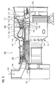
- FIG. 1 shows a layer system 1 according to the invention.
- the layer system 1 consists of a metallic substrate 4 which, in particular for components at high temperatures, consists of a nickel- or cobalt-based superalloy (FIG. 2).
- the NiCoCrAlY attachment layer 7 consists of one of these
- An aluminum oxide layer has already formed on this metallic bonding layer 7 before the application of further ceramic layers. During operation, such an aluminum oxide layer (TGO) is formed.
- An inner ceramic layer 10 preferably a fully or partially stabilized zirconium oxide layer, is preferably present on the metallic bonding layer 7 or on the aluminum oxide layer (not illustrated).
- yttria-stabilized zirconia preferably with 6wt% - 8wt% yttrium is used.
- calcium oxide, Ceria or hafnium oxide can be used to stabilize zirconia.
- the zirconium oxide is preferably applied as a plasma-sprayed layer, but can preferably also be applied as a columnar structure by means of electron beam evaporation (EBPVD).
- EBPVD electron beam evaporation
- an outer ceramic layer 13 which according to the invention comprises a mixed crystal of gadolinium, hafnium and zirconium with pyrochlore structure.
- the outer ceramic layer 13 Gadolinium (Gd) for A, hafnium and zirconium (Hf, Zr) is used for B, which is a mixed crystal structure Gd v (Zr x Hf y) O z. Again, small deviations from this stoichiometry may occur.
- the outer ceramic layer 13 also includes Gd v (Hf x Zr y ) O 7 .
- the outer ceramic layer 13 comprises Gd 2 (Hf x Zr y ) O z .
- any mixing ratios y: x of zirconium and hafnium can be used.
- a larger amount of zircon is used.
- mixing ratios of 10:90, 20:80, 30:70 or 40:60 are preferably used for hafnium to zirconium. It is also advantageous to use mixing ratios of 50:50, 60:40, 70:30, 80:20 or 90:10 for hafnium to zirconium.
- the layer may be made of a powder which gives the proportions of the above composition.
- the mixed crystals can also be produced during the coating process or by a heat treatment after the coating process.
- the layer thickness of the inner layer 10 is preferably between 10% and 50% of the total layer thickness D of inner layer 10 and outer layer 13.
- the layer thickness of the inner layer 10 is between 10% and 40% or between 10% and 30% of the total layer thickness. It is equally advantageous if the layer thickness of the inner layer 10 has 10% to 20% of the total layer thickness. It is likewise preferred if the layer thickness of the inner layer 10 is between 20% and 50% or between 20% and 40% of the total layer thickness. When the ratio of the inner layer 10 to the total layer thickness is between 20% and 30%, equally advantageous results are achieved.
- the layer thickness of the inner layer 10 is 30% to 50% of the total layer thickness. It is equally advantageous if the layer thickness of the inner layer 10 has 30% to 40% of the total layer thickness.
- the layer thickness of the inner layer 10 is between 40% and 50% of the total layer thickness.
- the pyrochlore phase has better thermal insulation properties than the ZrO 2 layer, the ZrO 2 layer can be made as thick as the pyrochlore phase.
- the inner ceramic layer 10 preferably has a thickness of 40 ⁇ m to 60 ⁇ m, in particular 50 ⁇ m ⁇ 10%.
- the total layer thickness of the inner layer 10 and the outer layer 13 is preferably 300 ⁇ m or preferably 400 ⁇ m.
- the maximum total layer thickness is advantageously 800 ⁇ m or preferably a maximum of 600 ⁇ m.
- FIG. 3 shows by way of example a gas turbine 100 in a longitudinal partial section.
- the gas turbine 100 has inside a rotatably mounted about a rotation axis 102 rotor 103 with a shaft 101, which is also referred to as a turbine runner.
- a compressor 105 for example, a toroidal combustion chamber 110, in particular annular combustion chamber, with a plurality of coaxially arranged burners 107, a turbine 108 and the exhaust housing 109th
- the annular combustion chamber 110 communicates with an annular annular hot gas channel 111, for example.
- Each turbine stage 112 is formed, for example, from two blade rings. As seen in the direction of flow of a working medium 113, in the hot gas channel 111 of a row of guide vanes 115, a series 125 formed of rotor blades 120 follows.
- the guide vanes 130 are fastened to an inner housing 138 of a stator 143, whereas the moving blades 120 of a row 125 are attached to the rotor 103 by means of a turbine disk 133, for example. Coupled to the rotor 103 is a generator or work machine (not shown).
- air 105 is sucked in and compressed by the compressor 105 through the intake housing 104.
- the compressed air provided at the turbine-side end of the compressor 105 is supplied to the burners 107 where it is mixed with a fuel.
- the mixture is then formed to form the working medium 113 in the combustion chamber 110 burned. From there, the working medium 113 flows along the hot gas channel 111 past the guide vanes 130 and the rotor blades 120. On the rotor blades 120, the working medium 113 expands in a pulse-transmitting manner, so that the rotor blades 120 drive the rotor 103 and drive the machine coupled to it.
- the components exposed to the hot working medium 113 are subject to thermal loads during operation of the gas turbine 100.
- the guide vanes 130 and rotor blades 120 of the first turbine stage 112, viewed in the flow direction of the working medium 113, are subjected to the greatest thermal stress in addition to the heat shield elements lining the annular combustion chamber 110. To withstand the prevailing temperatures, they can be cooled by means of a coolant.
- substrates of the components can have a directional structure, ie they are monocrystalline (SX structure) or have only longitudinal grains (DS structure).
- SX structure monocrystalline
- DS structure only longitudinal grains
- Such superalloys are for example from EP 1 204 776 B1 .
- EP 1 306 454 .
- the vane 130 has a guide vane foot (not shown here) facing the inner housing 138 of the turbine 108 and a vane head opposite the vane foot.
- the vane head faces the rotor 103 and fixed to a mounting ring 140 of the stator 143.
- FIG. 4 shows a perspective view of a moving blade 120 or guide blade 130 of a turbomachine that extends along a longitudinal axis 121.
- the turbomachine may be a gas turbine of an aircraft or a power plant for power generation, a steam turbine or a compressor.
- the blade 120, 130 has along the longitudinal axis 121 consecutively a fastening region 400, a blade platform 403 adjacent thereto and an airfoil 406 and a blade tip 415.
- the blade 130 may have at its blade tip 415 another platform (not shown).
- a blade root 183 is formed, which serves for attachment of the blades 120, 130 to a shaft or a disc (not shown).
- the blade root 183 is designed, for example, as a hammer head. Other designs as Christmas tree or Schwalbenschwanzfuß are possible.
- the blade 120, 130 has a leading edge 409 and a trailing edge 412 for a medium flowing past the airfoil 406.
- blades 120, 130 for example, solid metallic materials, in particular superalloys, are used in all regions 400, 403, 406 of the blade 120, 130.
- Such superalloys are for example from EP 1 204 776 B1 .
- EP 1 306 454 .
- the blade 120, 130 can be made by a casting process, also by directional solidification, by a forging process, by a milling process or combinations thereof.
- the blades 120, 130 may have coatings against corrosion or oxidation, e.g. (MCrAlX, M is at least one element of the group iron (Fe), cobalt (Co), nickel (Ni), X is an active element and stands for yttrium (Y) and / or silicon and / or at least one element of the rare earths, or hafnium (Hf)).
- M is at least one element of the group iron (Fe), cobalt (Co), nickel (Ni)
- X is an active element and stands for yttrium (Y) and / or silicon and / or at least one element of the rare earths, or hafnium (Hf)).
- Such alloys are known from the EP 0 486 489 B1 . EP 0 786 017 B1 . EP 0 412 397 B1 or EP 1 306 454 A1 which are to be part of this disclosure with regard to the chemical composition of the alloy.
- the density is preferably 95% of the theoretical
- thermal barrier coating On the MCrAlX may still be present a thermal barrier coating, which is preferably the outermost layer, and consists of the layer system 1 according to the invention.
- the thermal barrier coating covers the entire MCrAlX layer.
- suitable coating processes such as electron beam evaporation (EB-PVD), stalk-shaped grains are produced in the thermal barrier coating.
- APS atmospheric plasma spraying
- LPPS LPPS
- VPS vacuum plasma spraying
- CVD chemical vaporation
- the thermal barrier coating may have porous, micro- or macro-cracked grains for better thermal shock resistance.
- the thermal barrier coating is therefore preferably more porous than the MCrAlX layer.
- the blade 120, 130 may be hollow or solid. If the blade 120, 130 is to be cooled, it is hollow and may still film cooling holes 418 (indicated by dashed lines) on.
- FIG. 5 shows a combustion chamber 110 of the gas turbine 100.
- the combustion chamber 110 is designed, for example, as a so-called annular combustion chamber, in which a multiplicity of burners 107 arranged circumferentially around a rotation axis 102 open into a common combustion chamber space 154, which produce flames 156.
- the combustion chamber 110 is in their entirety designed as an annular structure which is positioned around the rotation axis 102 around.
- the combustion chamber 110 is designed for a comparatively high temperature of the working medium M of about 1000 ° C to 1600 ° C.
- the combustion chamber wall 153 is provided on its side facing the working medium M side with an inner lining formed from heat shield elements 155.
- the heat shield elements 155 are then, for example, hollow and possibly still have cooling holes (not shown) which open into the combustion chamber space 154.
- Each heat shield element 155 made of an alloy is equipped on the working medium side with a particularly heat-resistant protective layer (MCrAlX layer and / or ceramic coating) or is made of high-temperature-resistant material (solid ceramic blocks).
- M is at least one element of the group iron (Fe), cobalt (Co), nickel (Ni), X is an active element and stands for yttrium (Y) and / or silicon and / or at least one element of the rare earths, or hafnium (Hf).
- MCrAlX means: M is at least one element of the group iron (Fe), cobalt (Co), nickel (Ni), X is an active element and stands for yttrium (Y) and / or silicon and / or at least one element of the rare earths, or hafnium (Hf).
- Such alloys are known from the EP 0 486 489 B1 .
- MCrAlX On the MCrAlX can still be present, for example, a ceramic thermal barrier coating and consists and consists of the layer system 1 according to the invention.
- thermal barrier coating By means of suitable coating processes, such as electron beam evaporation (EB-PVD), stalk-shaped grains are produced in the thermal barrier coating.
- EB-PVD electron beam evaporation
- Other coating methods are conceivable, for example atmospheric plasma spraying (APS), LPPS, VPS or CVD.
- APS atmospheric plasma spraying
- LPPS LPPS
- VPS VPS
- CVD chemical vapor deposition
- the thermal barrier coating may have porous, micro- or macro-cracked grains for better thermal shock resistance.
- Refurbishment means that turbine blades 120, 130, heat shield elements 155 may need to be deprotected (e.g., by sandblasting) after use. This is followed by removal of the corrosion and / or oxidation layers or products. Optionally, cracks in the turbine blade 120, 130 or the heat shield element 155 are also repaired. This is followed by a re-coating of the turbine blades 120, 130, heat shield elements 155 and a renewed use of the turbine blades 120, 130 or the heat shield elements 155.
Abstract
Description
Die Erfindung betrifft ein Schichtsystem mit Pyrochloren.The invention relates to a layer system with pyrochlors.
Ein solches Schichtsystem weist ein Substrat mit einer Metalllegierung auf der Basis von Nickel oder Kobalt auf. Derartige Erzeugnisse dienen vor allem als Bauteil einer Gasturbine, insbesondere als Gasturbinenschaufeln oder Hitzeschilde. Die Bauteile sind einem Heißgasstrom von aggressiven Verbrennungsgasen ausgesetzt. Daher müssen sie hohen thermischen Belastungen Stand halten können. Des Weiteren ist es erforderlich, dass diese Bauteile oxidations- und korrosionsbeständig sind. Vor allem an bewegliche Bauteile, z. B. Gasturbinenschaufeln, aber auch an statische Bauteile sind fernerhin mechanische Anforderungen zu stellen. Die Leistung und der Wirkungsgrad einer Gasturbine, in der heißgasbelastbare Bauteile Verwendung finden, steigen mit zunehmender Betriebstemperatur. Um einen hohen Wirkungsgrad und eine hohe Leistung zu erzielen, werden durch die hohen Temperaturen besonders belastete Komponenten der Gasturbinen mit einem keramischen Werkstoff beschichtet. Dieser wirkt als Wärmedämmschicht zwischen dem Heißgasstrom und dem metallischen Substrat.
Vor dem aggressiven Heißgasstrom wird der metallische Grundkörper durch Beschichtungen geschützt. Dabei weisen moderne Bauteile zumeist mehrere Beschichtungen auf, die jeweils spezifische Aufgaben erfüllen. Es liegt somit ein Mehrschichtsystem vor.
Da Leistung und Wirkungsgrad von Gasturbinen mit zunehmender Betriebstemperatur steigen, wurde immer wieder versucht, durch Verbesserung des Beschichtungssystems eine höhere Leistungsfähigkeit von Gasturbinen zu erzielen.Such a layer system comprises a substrate with a metal alloy based on nickel or cobalt. Such products serve primarily as a component of a gas turbine, in particular as gas turbine blades or heat shields. The components are exposed to a hot gas stream of aggressive combustion gases. Therefore, they must be able to withstand high thermal loads. Furthermore, it is necessary that these components are resistant to oxidation and corrosion. Especially on moving components, eg. As gas turbine blades, but also to static components are furthermore mechanical requirements. The performance and efficiency of a gas turbine, in which hot gas-resistant components are used, increase with increasing operating temperature. In order to achieve a high degree of efficiency and high performance, the components of the gas turbines, which are subjected to particularly high temperatures, are coated with a ceramic material. This acts as a thermal barrier coating between the hot gas flow and the metallic substrate.
Before the aggressive hot gas flow, the metallic base body is protected by coatings. In this case, modern components usually have several coatings, each of which fulfills specific tasks. There is thus a multi-layer system.
As power and efficiency of gas turbines increase with increasing operating temperature, it has been repeatedly attempted to improve the performance of gas turbines by improving the coating system.
Die
Die
Es ist daher Aufgabe der Erfindung ein Schichtsystem aufzuzeigen, das gute wärmedämmende Eigenschaften sowie eine gute Anbindung an das Substrat und damit eine lange Lebensdauer aufweist.It is therefore an object of the invention to show a layer system which has good heat-insulating properties and a good connection to the substrate and thus a long service life.
Die Aufgabe wird gelöst durch ein Schichtsystem gemäß Anspruch 1.The object is achieved by a layer system according to claim 1.
Der Erfindung liegt die Erkenntnis zugrunde, dass das gesamte System als Einheit betrachtet werden muss und nicht einzelne Schichten oder einzelne Schichten untereinander isoliert von einander betrachtet und optimiert werden dürfen, um eine lange Lebensdauer zu erzielen.The invention is based on the recognition that the entire system must be regarded as a single unit and that individual layers or individual layers may not be viewed and optimized in isolation from each other in order to achieve a long service life.
In den Unteransprüchen sind weitere vorteilhafte Maßnahmen aufgeführt, die beliebig in vorteilhafter Art und Weise kombiniert werden können.In the dependent claims further advantageous measures are listed, which can be combined in any advantageous manner.
Das erfindungsgemäße Schichtsystem besteht aus einer äußeren keramischen Schicht, die einen Mischkristall aus Gadoliniumzirkonat und Gadoliniumhafnat aufweist, der besonders gute thermische Eigenschaften (an das Substrat angepasster Ausdehnungskoeffizient, geringer Wärmeleitkoeffizient) aufweist und sehr gut harmoniert mit einer Zwischenschicht und dem Substrat des Bauteils.The layer system according to the invention consists of an outer ceramic layer which has a mixed crystal of gadolinium zirconate and gadolinium hafnate, which has particularly good thermal properties (expansion coefficient adapted to the substrate, low thermal conductivity coefficient) and harmonizes very well with an intermediate layer and the substrate of the component.
Ausführungsbeispiele der Erfindung werden nachfolgend unter Bezugnahme auf die Zeichnungen noch näher erläutert.Embodiments of the invention will be explained in more detail with reference to the drawings.
Es zeigen
- Figur 1
- ein erfindungsgemäßes Schichtsystem,
Figur 2- Zusammensetzungen von Superlegierungen,
- Figur 3
- eine Gasturbine,
Figur 4- eine perspektivische Ansicht einer Turbinenschaufel und
- Figur 5
- eine perspektivische Ansicht einer Brennkammer.
- FIG. 1
- a layer system according to the invention,
- FIG. 2
- Compositions of superalloys,
- FIG. 3
- a gas turbine,
- FIG. 4
- a perspective view of a turbine blade and
- FIG. 5
- a perspective view of a combustion chamber.
Figur 1 zeigt ein erfindungsgemäßes Schichtsystem 1.FIG. 1 shows a layer system 1 according to the invention.
Das Schichtsystem 1 besteht aus einem metallischen Substrat 4, das insbesondere für Bauteile bei hohen Temperaturen aus einer nickel- oder kobaltbasierten Superlegierung (Fig. 2) besteht.
Direkt auf dem Substrat 4 ist vorzugsweise eine metallische Anbindungsschicht 7 des Typs MCrAlX, insbesondere des Typs NiCoCrALX vorhanden, die vorzugsweise entweder (11 - 13)wt% Kobalt, (20 - 22)wt% Chrom, (10,5 - 11,5)wt% Aluminium, (0,3 - 0,5)wt% Yttrium (=X), (1,5 - 2,5)wt% Rhenium und Rest Nickel oder vorzugsweise aus (24 - 26)wt% Kobalt, (16 - 18)wt% Chrom, (9,5 - 11)wt% Aluminium, (0,3 - 0,5)wt% Yttrium (=X), (1 - 1,8)wt% Rhenium und Rest Nickel aufweist. Insbesondere besteht die NiCoCrAlY Anbindungsschicht 7 aus einer dieser beiden Zusammensetzungen.The layer system 1 consists of a
Directly on the
Auf dieser metallischen Anbindungsschicht 7 ist bereits vor dem Aufbringen weiterer keramischer Schichten eine Aluminiumoxidschicht entstanden während des Betriebs entsteht eine solche Aluminiumoxidschicht (TGO).
Auf der metallischen Anbindungsschicht 7 oder auf der Aluminiumoxidschicht (nicht dargestellt) ist vorzugsweise eine innere keramische Schicht 10, vorzugsweise eine vollständig oder teilweise stabilisierte Zirkonoxidschicht vorhanden. Vorzugsweise wird Yttrium-stabilisiertes Zirkonoxid, vorzugsweise mit 6wt% - 8wt% Yttrium verwendet. Ebenso kann Kalziumoxid, Ceroxid oder Hafniumoxid zur Stabilisierung von Zirkonoxid verwendet werden.
Das Zirkonoxid wird vorzugsweise als plasmagespritzte Schicht aufgetragen, kann vorzugsweise auch als kolumnare Struktur mittels Elektronenstrahlverdampfen (EBPVD) aufgebracht werden.An aluminum oxide layer has already formed on this
An inner
The zirconium oxide is preferably applied as a plasma-sprayed layer, but can preferably also be applied as a columnar structure by means of electron beam evaporation (EBPVD).
Auf der TGO, auf der Anbindungsschicht 7 oder auf der inneren Schicht 10 ist eine äußere keramische Schicht 13 aufgebracht, die erfindungsgemäß einen Mischkristall aus Gadolinium, Hafnium und Zirkon mit Pyrochlorstruktur umfasst.
Eine Pyrochlorstruktur weist die Summenformel A2B2O7 auf oder allgemein AvBxOz wobei v = 2, x = 2 und z = 7 ist. Abweichungen von dieser stöchiometrischen Zusammensetzung für v, x und z können durch Fehlstellen oder geringe, bewusste oder unbewusste Dotierungen entstehen.
Für die erfindungsgemäße äußere keramische Schicht 13 wird Gadolinium (Gd) für A, Hafnium und Zirkon (Hf, Zr) für B verwendet, also eine Mischkristallstruktur Gdv(HfxZry)Oz. Auch hier können geringe Abweichungen von dieser Stöchiometrie auftreten.
Vorzugsweise umfasst die äußere keramische Schicht 13 Gdv(HfxZry)Oz mit x + y = 2.
Vorzugsweise umfasst die äußere keramische Schicht 13 auch Gdv(HfxZry)O7.
Vorzugsweise umfasst die äußere keramische Schicht 13 Gd2(HfxZry)Oz.
Vorzugsweise besteht die äußere keramische Schicht 13 aus Gdv(HfxZry)Oz, insbesondere mit v = 2, x+y = 2 und z = 7.On the TGO, on the
A pyrochlore structure has the molecular formula A 2 B 2 O 7 or, more generally, A v B x O z where v = 2, x = 2 and z = 7. Deviations from this stoichiometric composition for v, x, and z may arise from defects or small, deliberate or unconscious dopants.
For the inventive outer
Preferably, the outer
Preferably, the outer
Preferably, the outer
The outer
Dabei können beliebige Mischungsverhältnisse y:x von Zirkon und Hafnium verwendet werden.
Vorzugsweise wird ein größerer Anteil von Zirkon verwendet. Ebenso werden vorzugsweise Mischungsverhältnisse von 10:90, 20:80, 30:70 oder 40:60 für Hafnium zu Zirkon verwendet. Weiterhin vorteilhaft ist es, Mischungsverhältnisse von 50:50, 60:40, 70:30, 80:20 oder 90:10 für Hafnium zu Zirkon zu verwenden.In this case, any mixing ratios y: x of zirconium and hafnium can be used.
Preferably, a larger amount of zircon is used. Likewise, mixing ratios of 10:90, 20:80, 30:70 or 40:60 are preferably used for hafnium to zirconium. It is also advantageous to use mixing ratios of 50:50, 60:40, 70:30, 80:20 or 90:10 for hafnium to zirconium.
Für die Verhältnisse von x zu y gelten also vorteilhafter Weise genannte Angaben für das Verhältnis von Hafnium zu Zirkon (Hf : Zr = 80:20 entspricht y:x= 1.6 : 0.4).The ratios of hafnium to zircon (Hf: Zr = 80:20 corresponds to y: x = 1.6: 0.4) apply to the ratios of x to y in an advantageous manner.
Die Schicht kann aus einem Pulver hergestellt worden sein, das die Anteile der oben genannten Zusammensetzung ergibt. Ebenso können sich die Mischkristalle auch beim Beschichtungsprozess oder durch eine Wärmebehandlung nach dem Beschichtungsprozess erzeugt werden.The layer may be made of a powder which gives the proportions of the above composition. Likewise, the mixed crystals can also be produced during the coating process or by a heat treatment after the coating process.
Die Schichtdicke der inneren Schicht 10 beträgt vorzugsweise zwischen 10% und 50% der Gesamtschichtdicke D von innerer Schicht 10 und äußerer Schicht 13.
Vorzugsweise liegt die Schichtdicke der inneren Schicht 10 zwischen 10% und 40% oder zwischen 10% und 30% der Gesamtschichtdicke.
Ebenso vorteilhaft ist es, wenn die Schichtdicke der inneren Schicht 10 10% bis 20% der Gesamtschichtdicke aufweist. Ebenso vorzugsweise ist es, wenn die Schichtdicke der inneren Schicht 10 zwischen 20% und 50% oder zwischen 20% und 40% der Gesamtschichtdicke beträgt.
Wenn der Anteil der inneren Schicht 10 an der Gesamtschichtdicke zwischen 20% und 30% liegt, werden ebenso vorteilhafte Ergebnisse erzielt.
Vorzugsweise beträgt die Schichtdicke der inneren Schicht 10 30% bis 50% der Gesamtschichtdicke.
Ebenso vorteilhaft ist es, wenn die Schichtdicke der inneren Schicht 10 30% bis 40% der Gesamtschichtdicke aufweist. Ebenso vorzugsweise ist es, wenn die Schichtdicke der inneren Schicht 10 zwischen 40% und 50% der Gesamtschichtdicke beträgt.
Obwohl die Pyrochlorphase bessere Wärmedämmungseigenschaften aufweist als die ZrO2-Schicht, kann die ZrO2-Schicht genauso dick ausgeführt werden wie die Pyrochlorphase.The layer thickness of the
Preferably, the layer thickness of the
It is equally advantageous if the layer thickness of the
When the ratio of the
Preferably, the layer thickness of the
It is equally advantageous if the layer thickness of the
Although the pyrochlore phase has better thermal insulation properties than the ZrO 2 layer, the ZrO 2 layer can be made as thick as the pyrochlore phase.
Die innere keramische Schicht 10 hat vorzugsweise eine Dicke von 40µm bis 60µm, insbesondere 50µm ± 10 %.The inner
Die Gesamtschichtdicke von der inneren Schicht 10 und der äußeren Schicht 13 beträgt vorzugsweise 300µm oder vorzugsweise 400 µm. Die maximale Gesamtschichtdicke beträgt vorteilhafterweise 800µm oder vorzugsweise maximal 600µm.The total layer thickness of the
Die Figur 3 zeigt beispielhaft eine Gasturbine 100 in einem Längsteilschnitt.
Die Gasturbine 100 weist im Inneren einen um eine Rotationsachse 102 drehgelagerten Rotor 103 mit einer Welle 101 auf, der auch als Turbinenläufer bezeichnet wird.
Entlang des Rotors 103 folgen aufeinander ein Ansauggehäuse 104, ein Verdichter 105, eine beispielsweise torusartige Brennkammer 110, insbesondere Ringbrennkammer, mit mehreren koaxial angeordneten Brennern 107, eine Turbine 108 und das Abgasgehäuse 109.
Die Ringbrennkammer 110 kommuniziert mit einem beispielsweise ringförmigen Heißgaskanal 111. Dort bilden beispielsweise vier hintereinander geschaltete Turbinenstufen 112 die Turbine 108.
Jede Turbinenstufe 112 ist beispielsweise aus zwei Schaufelringen gebildet. In Strömungsrichtung eines Arbeitsmediums 113 gesehen folgt im Heißgaskanal 111 einer Leitschaufelreihe 115 eine aus Laufschaufeln 120 gebildete Reihe 125.FIG. 3 shows by way of example a
The
Along the
The
Each
Die Leitschaufeln 130 sind dabei an einem Innengehäuse 138 eines Stators 143 befestigt, wohingegen die Laufschaufeln 120 einer Reihe 125 beispielsweise mittels einer Turbinenscheibe 133 am Rotor 103 angebracht sind.
An dem Rotor 103 angekoppelt ist ein Generator oder eine Arbeitsmaschine (nicht dargestellt).The guide vanes 130 are fastened to an
Coupled to the
Während des Betriebes der Gasturbine 100 wird vom Verdichter 105 durch das Ansauggehäuse 104 Luft 135 angesaugt und verdichtet. Die am turbinenseitigen Ende des Verdichters 105 bereitgestellte verdichtete Luft wird zu den Brennern 107 geführt und dort mit einem Brennmittel vermischt. Das Gemisch wird dann unter Bildung des Arbeitsmediums 113 in der Brennkammer 110 verbrannt. Von dort aus strömt das Arbeitsmedium 113 entlang des Heißgaskanals 111 vorbei an den Leitschaufeln 130 und den Laufschaufeln 120. An den Laufschaufeln 120 entspannt sich das Arbeitsmedium 113 impulsübertragend, so dass die Laufschaufeln 120 den Rotor 103 antreiben und dieser die an ihn angekoppelte Arbeitsmaschine.During operation of the
Die dem heißen Arbeitsmedium 113 ausgesetzten Bauteile unterliegen während des Betriebes der Gasturbine 100 thermischen Belastungen. Die Leitschaufeln 130 und Laufschaufeln 120 der in Strömungsrichtung des Arbeitsmediums 113 gesehen ersten Turbinenstufe 112 werden neben den die Ringbrennkammer 110 auskleidenden Hitzeschildelementen am meisten thermisch belastet.
Um den dort herrschenden Temperaturen standzuhalten, können diese mittels eines Kühlmittels gekühlt werden.
Ebenso können Substrate der Bauteile eine gerichtete Struktur aufweisen, d.h. sie sind einkristallin (SX-Struktur) oder weisen nur längsgerichtete Körner auf (DS-Struktur).
Als Material für die Bauteile, insbesondere für die Turbinenschaufel 120, 130 und Bauteile der Brennkammer 110 werden beispielsweise eisen-, nickel- oder kobaltbasierte Superlegierungen verwendet.
Solche Superlegierungen sind beispielsweise aus der
To withstand the prevailing temperatures, they can be cooled by means of a coolant.
Likewise, substrates of the components can have a directional structure, ie they are monocrystalline (SX structure) or have only longitudinal grains (DS structure).
As the material for the components, in particular for the
Such superalloys are for example from
Die Leitschaufel 130 weist einen dem Innengehäuse 138 der Turbine 108 zugewandten Leitschaufelfuß (hier nicht dargestellt) und einen dem Leitschaufelfuß gegenüberliegenden Leitschaufelkopf auf. Der Leitschaufelkopf ist dem Rotor 103 zugewandt und an einem Befestigungsring 140 des Stators 143 festgelegt.The
Die Figur 4 zeigt in perspektivischer Ansicht eine Laufschaufel 120 oder Leitschaufel 130 einer Strömungsmaschine, die sich entlang einer Längsachse 121 erstreckt.FIG. 4 shows a perspective view of a moving
Die Strömungsmaschine kann eine Gasturbine eines Flugzeugs oder eines Kraftwerks zur Elektrizitätserzeugung, eine Dampfturbine oder ein Kompressor sein.The turbomachine may be a gas turbine of an aircraft or a power plant for power generation, a steam turbine or a compressor.
Die Schaufel 120, 130 weist entlang der Längsachse 121 aufeinander folgend einen Befestigungsbereich 400, eine daran angrenzende Schaufelplattform 403 sowie ein Schaufelblatt 406 und eine Schaufelspitze 415 auf.
Als Leitschaufel 130 kann die Schaufel 130 an ihrer Schaufelspitze 415 eine weitere Plattform aufweisen (nicht dargestellt).The
As a
Im Befestigungsbereich 400 ist ein Schaufelfuß 183 gebildet, der zur Befestigung der Laufschaufeln 120, 130 an einer Welle oder einer Scheibe dient (nicht dargestellt).
Der Schaufelfuß 183 ist beispielsweise als Hammerkopf ausgestaltet. Andere Ausgestaltungen als Tannenbaum- oder Schwalbenschwanzfuß sind möglich.
Die Schaufel 120, 130 weist für ein Medium, das an dem Schaufelblatt 406 vorbeiströmt, eine Anströmkante 409 und eine Abströmkante 412 auf.In the mounting
The
The
Bei herkömmlichen Schaufeln 120, 130 werden in allen Bereichen 400, 403, 406 der Schaufel 120, 130 beispielsweise massive metallische Werkstoffe, insbesondere Superlegierungen verwendet.
Solche Superlegierungen sind beispielsweise aus der
Die Schaufel 120, 130 kann hierbei durch ein Gussverfahren, auch mittels gerichteter Erstarrung, durch ein Schmiedeverfahren, durch ein Fräsverfahren oder Kombinationen daraus gefertigt sein.In
Such superalloys are for example from
The
Werkstücke mit einkristalliner Struktur oder Strukturen werden als Bauteile für Maschinen eingesetzt, die im Betrieb hohen mechanischen, thermischen und/oder chemischen Belastungen ausgesetzt sind.
Die Fertigung von derartigen einkristallinen Werkstücken erfolgt z.B. durch gerichtetes Erstarren aus der Schmelze. Es handelt sich dabei um Gießverfahren, bei denen die flüssige metallische Legierung zur einkristallinen Struktur, d.h. zum einkristallinen Werkstück, oder gerichtet erstarrt.
Dabei werden dendritische Kristalle entlang dem Wärmefluss ausgerichtet und bilden entweder eine stängelkristalline Kornstruktur (kolumnar, d.h. Körner, die über die ganze Länge des Werkstückes verlaufen und hier, dem allgemeinen Sprachgebrauch nach, als gerichtet erstarrt bezeichnet werden) oder eine einkristalline Struktur, d.h. das ganze Werkstück besteht aus einem einzigen Kristall. In diesen Verfahren muss man den Übergang zur globulitischen (polykristallinen) Erstarrung meiden, da sich durch ungerichtetes Wachstum notwendigerweise transversale und longitudinale Korngrenzen ausbilden, welche die guten Eigenschaften des gerichtet erstarrten oder einkristallinen Bauteiles zunichte machen.
Ist allgemein von gerichtet erstarrten Gefügen die Rede, so sind damit sowohl Einkristalle gemeint, die keine Korngrenzen oder höchstens Kleinwinkelkorngrenzen aufweisen, als auch Stängelkristallstrukturen, die wohl in longitudinaler Richtung verlaufende Korngrenzen, aber keine transversalen Korngrenzen aufweisen. Bei diesen zweitgenannten kristallinen Strukturen spricht man auch von gerichtet erstarrten Gefügen (directionally solidified structures).
Solche Verfahren sind aus der
The production of such monocrystalline workpieces, for example, by directed solidification from the melt. These are casting methods in which the liquid metallic alloy solidifies into a monocrystalline structure, ie a single-crystal workpiece, or directionally.
Here, dendritic crystals are aligned along the heat flow and form either a columnar grain structure (columnar, ie grains that run the entire length of the workpiece and here, in common parlance, referred to as directionally solidified) or a monocrystalline structure, ie the whole Workpiece consists of a single crystal. In these processes, it is necessary to avoid the transition to globulitic (polycrystalline) solidification, since non-directional growth necessarily produces transverse and longitudinal grain boundaries which negate the good properties of the directionally solidified or monocrystalline component.
The term generally refers to directionally solidified microstructures, which means both single crystals that have no grain boundaries or at most small angle grain boundaries, and stem crystal structures that have probably longitudinal grain boundaries but no transverse grain boundaries. These second-mentioned crystalline structures are also known as directionally solidified structures.
Such methods are known from
Ebenso können die Schaufeln 120, 130 Beschichtungen gegen Korrosion oder Oxidation aufweisen, z. B. (MCrAlX; M ist zumindest ein Element der Gruppe Eisen (Fe), Kobalt (Co), Nickel (Ni), X ist ein Aktivelement und steht für Yttrium (Y) und/oder Silizium und/oder zumindest ein Element der Seltenen Erden, bzw. Hafnium (Hf)). Solche Legierungen sind bekannt aus der
Die Dichte liegt vorzugsweise bei 95% der theoretischen Dichte.
Auf der MCrAlX-Schicht (als Zwischenschicht oder als äußerste Schicht) bildet sich eine schützende Aluminiumoxidschicht (TGO = thermal grown oxide layer).Likewise, the
The density is preferably 95% of the theoretical density.
A protective aluminum oxide layer (TGO = thermal grown oxide layer) is formed on the MCrAlX layer (as an intermediate layer or as the outermost layer).
Auf der MCrAlX kann noch eine Wärmedämmschicht vorhanden sein, die vorzugsweise die äußerste Schicht ist, und besteht aus dem erfindungsgemäßen Schichtsystem 1.
Die Wärmedämmschicht bedeckt die gesamte MCrAlX-Schicht. Durch geeignete Beschichtungsverfahren wie z.B. Elektronenstrahlverdampfen (EB-PVD) werden stängelförmige Körner in der Wärmedämmschicht erzeugt.
Andere Beschichtungsverfahren sind denkbar, z.B. atmosphärisches Plasmaspritzen (APS), LPPS, VPS oder CVD. Die Wärmedämmschicht kann poröse, mikro- oder makrorissbehaftete Körner zur besseren Thermoschockbeständigkeit aufweisen. Die Wärmedämmschicht ist also vorzugsweise poröser als die MCrAlX-Schicht.On the MCrAlX may still be present a thermal barrier coating, which is preferably the outermost layer, and consists of the layer system 1 according to the invention.
The thermal barrier coating covers the entire MCrAlX layer. By means of suitable coating processes, such as electron beam evaporation (EB-PVD), stalk-shaped grains are produced in the thermal barrier coating.
Other coating methods are conceivable, for example atmospheric plasma spraying (APS), LPPS, VPS or CVD. The thermal barrier coating may have porous, micro- or macro-cracked grains for better thermal shock resistance. The thermal barrier coating is therefore preferably more porous than the MCrAlX layer.
Die Schaufel 120, 130 kann hohl oder massiv ausgeführt sein. Wenn die Schaufel 120, 130 gekühlt werden soll, ist sie hohl und weist ggf. noch Filmkühllöcher 418 (gestrichelt angedeutet) auf.The
Die Figur 5 zeigt eine Brennkammer 110 der Gasturbine 100. Die Brennkammer 110 ist beispielsweise als so genannte Ringbrennkammer ausgestaltet, bei der eine Vielzahl von in Umfangsrichtung um eine Rotationsachse 102 herum angeordneten Brennern 107 in einen gemeinsamen Brennkammerraum 154 münden, die Flammen 156 erzeugen. Dazu ist die Brennkammer 110 in ihrer Gesamtheit als ringförmige Struktur ausgestaltet, die um die Rotationsachse 102 herum positioniert ist.FIG. 5 shows a
Zur Erzielung eines vergleichsweise hohen Wirkungsgrades ist die Brennkammer 110 für eine vergleichsweise hohe Temperatur des Arbeitsmediums M von etwa 1000°C bis 1600°C ausgelegt. Um auch bei diesen, für die Materialien ungünstigen Betriebsparametern eine vergleichsweise lange Betriebsdauer zu ermöglichen, ist die Brennkammerwand 153 auf ihrer dem Arbeitsmedium M zugewandten Seite mit einer aus Hitzeschildelementen 155 gebildeten Innenauskleidung versehen.To achieve a comparatively high efficiency, the
Aufgrund der hohen Temperaturen im Inneren der Brennkammer 110 kann zudem für die Hitzeschildelemente 155 bzw. für deren Halteelemente ein Kühlsystem vorgesehen sein. Die Hitzeschildelemente 155 sind dann beispielsweise hohl und weisen ggf. noch in den Brennkammerraum 154 mündende Kühllöcher (nicht dargestellt) auf.Due to the high temperatures inside the
Jedes Hitzeschildelement 155 aus einer Legierung ist arbeitsmediumsseitig mit einer besonders hitzebeständigen Schutzschicht (MCrAlX-Schicht und/oder keramische Beschichtung) ausgestattet oder ist aus hochtemperaturbeständigem Material (massive keramische Steine) gefertigt.
Diese Schutzschichten können ähnlich der Turbinenschaufeln sein, also bedeutet beispielsweise MCrAlX: M ist zumindest ein Element der Gruppe Eisen (Fe), Kobalt (Co), Nickel (Ni), X ist ein Aktivelement und steht für Yttrium (Y) und/oder Silizium und/oder zumindest ein Element der Seltenen Erden, bzw. Hafnium (Hf). Solche Legierungen sind bekannt aus der
These protective layers may be similar to the turbine blades, so for example MCrAlX means: M is at least one element of the group iron (Fe), cobalt (Co), nickel (Ni), X is an active element and stands for yttrium (Y) and / or silicon and / or at least one element of the rare earths, or hafnium (Hf). Such alloys are known from the
Auf der MCrAlX kann noch eine beispielsweise keramische Wärmedämmschicht vorhanden sein und besteht und besteht aus dem erfindungsgemäßen Schichtsystem 1.On the MCrAlX can still be present, for example, a ceramic thermal barrier coating and consists and consists of the layer system 1 according to the invention.
Durch geeignete Beschichtungsverfahren wie z.B. Elektronenstrahlverdampfen (EB-PVD) werden stängelförmige Körner in der Wärmedämmschicht erzeugt.
Andere Beschichtungsverfahren sind denkbar, z.B. atmosphärisches Plasmaspritzen (APS), LPPS, VPS oder CVD. Die Wärmedämmschicht kann poröse, mikro- oder makrorissbehaftete Körner zur besseren Thermoschockbeständigkeit aufweisen.By means of suitable coating processes, such as electron beam evaporation (EB-PVD), stalk-shaped grains are produced in the thermal barrier coating.
Other coating methods are conceivable, for example atmospheric plasma spraying (APS), LPPS, VPS or CVD. The thermal barrier coating may have porous, micro- or macro-cracked grains for better thermal shock resistance.
Wiederaufarbeitung (Refurbishment) bedeutet, dass Turbinenschaufeln 120, 130, Hitzeschildelemente 155 nach ihrem Einsatz gegebenenfalls von Schutzschichten befreit werden müssen (z.B. durch Sandstrahlen). Danach erfolgt eine Entfernung der Korrosions- und/oder Oxidationsschichten bzw. -produkte. Gegebenenfalls werden auch noch Risse in der Turbinenschaufel 120, 130 oder dem Hitzeschildelement 155 repariert. Danach erfolgt eine Wiederbeschichtung der Turbinenschaufeln 120, 130, Hitzeschildelemente 155 und ein erneuter Einsatz der Turbinenschaufeln 120, 130 oder der Hitzeschildelemente 155.Refurbishment means that
Claims (25)
aufweisend
ein Substrat (4),
auf dem eine äußere keramische Schicht (13) vorhanden ist, die eine Pyrochlorstruktur Gdv(ZrxHfy)Oz umfasst.layer system
including
a substrate (4),
on which an outer ceramic layer (13) is present, which comprises a pyrochlore structure Gd v (Zr x Hf y ) O z .
bei dem
die äußere keramische Schicht (13) Gdv(ZrxHfy)Oz mit x + y = 2 umfasst.Layer system according to claim 1,
in which
the outer ceramic layer (13) comprises Gd v (Zr x Hf y ) O z with x + y = 2.
bei dem
die äußere keramische Schicht (13) Gd2(ZrxHfy)Oz umfasstLayer system according to claim 1 or 2,
in which
the outer ceramic layer (13) comprises Gd 2 (Zr x Hf y ) O z
bei dem
die äußere keramische Schicht (13) Gdv(ZrxHfy)O7 umfasst.Layer system according to claim 1, 2 or 3,
in which
the outer ceramic layer (13) comprises Gd v (Zr x Hf y ) O 7 .
bei dem
die äußere keramische Schicht (13) aus Gdv(ZrxHfy)Oz besteht.Layer system according to claim 1, 2, 3 or 4,
in which
the outer ceramic layer (13) consists of Gd v (Zr x Hf y ) O z .
bei dem
die äußere keramische Schicht (13) aus Gdv(ZrxHfy)Oz mit x + y = 2,
insbesondere aus Gd2(ZrxHfy)O7, besteht.Layer system according to claim 1, 2, 3, 4 or 5,
in which
the outer ceramic layer (13) of Gd v (Zr x Hf y ) O z with x + y = 2,
in particular Gd 2 (Zr x Hf y ) O 7 , consists.
unter der äußeren keramischen Schicht (13) eine innere keramische Schicht (10),
insbesondere eine stabilisierte Zirkonoxidschicht, insbesondere eine Yttrium-stabilisierte Zirkonoxidschicht, vorhanden ist.Layer system according to one or more of the preceding claims, in which
an inner ceramic layer (10) under the outer ceramic layer (13),
in particular a stabilized zirconium oxide layer, in particular an yttrium-stabilized zirconium oxide layer, is present.
bei dem
die innere keramische Schicht (10) aus einer 6wt% - 8wt% Yttrium-stabilisierten Zirkonoxidschicht besteht.Layer system according to claim 7,
in which
the inner ceramic layer (10) consists of a 6wt% - 8wt% yttrium stabilized zirconium oxide layer.
bei dem
die innere keramische Schicht (10) eine Schichtdicke zwischen 10% und 50% der Gesamtschichtdicke (D) von der inneren keramischen Schicht (10) und der äußeren keramischen Schicht (13) aufweist.Layer system according to claim 7 or 8,
in which
the inner ceramic layer (10) has a layer thickness between 10% and 50% of the total layer thickness (D) of the inner ceramic layer (10) and the outer ceramic layer (13).
bei dem
die Schichtdicke der inneren keramischen Schicht (10) und der äußeren keramischen Schicht (13) zusammen 300µm beträgt.Layer system according to claim 7, 8 or 9,
in which
the layer thickness of the inner ceramic layer (10) and the outer ceramic layer (13) together is 300 μm.
bei dem
die Schichtdicke der inneren Schicht (10) und der äußeren Schicht (13) zusammen 400µm beträgt.Layer system according to claim 7, 8 or 9,
in which
the layer thickness of the inner layer (10) and the outer layer (13) together is 400 μm.
bei dem
auf dem Substrat (4) und unter der inneren keramischen Schicht (10) oder unter der äußeren keramischen Schicht (13) eine metallische Anbindungsschicht (7),
insbesondere aus einer NiCoCrAlX-Legierung, vorhanden ist.Layer system according to claim 1 or 7,
in which
a metallic bonding layer (7) on the substrate (4) and under the inner ceramic layer (10) or under the outer ceramic layer (13),
in particular of a NiCoCrAlX alloy, is present.
bei dem
die metallische Anbindungsschicht (7) die Zusammensetzung (in wt%)
in which
the metallic bonding layer (7) the composition (in wt%)
bei dem
die metallische Anbindungsschicht (7) die Zusammensetzung (in wt%)
in which
the metallic bonding layer (7) the composition (in wt%)
bei dem
das Mischungsverhältnis von Hafnium und Zirkon 10:90 beträgt.Layer system according to claim 1, 2, 3, 4, 5 or 6,
in which
the mixing ratio of hafnium and zirconium is 10:90.
bei dem
das Mischungsverhältnis von Hafnium und Zirkon 20:80 beträgt.Layer system according to claim 1, 2, 3, 4, 5 or 6,
in which
the mixing ratio of hafnium and zirconium is 20:80.
bei dem
das Mischungsverhältnis von Hafnium und Zirkon 30:70 beträgt.Layer system according to claim 1, 2, 3, 4, 5 or 6,
in which
the mixing ratio of hafnium and zirconium is 30:70.
bei dem
das Mischungsverhältnis von Hafnium und Zirkon 40:60 beträgt.Layer system according to claim 1, 2, 3, 4, 5 or 6,
in which
the mixing ratio of hafnium and zirconium is 40:60.
bei dem
das Mischungsverhältnis von Hafnium und Zirkon 50:50 beträgt.Layer system according to claim 1, 2, 3, 4, 5 or 6,
in which
the mixing ratio of hafnium and zirconium is 50:50.
bei dem
das Mischungsverhältnis von Hafnium und Zirkon 60:40 beträgt.Layer system according to claim 1, 2, 3, 4, 5 or 6,
in which
the mixing ratio of hafnium and zirconium is 60:40.
bei dem
das Mischungsverhältnis von Hafnium und Zirkon 70:30 beträgt.Layer system according to claim 1, 2, 3, 4, 5 or 6,
in which
the mixing ratio of hafnium and zirconium is 70:30.
bei dem
das Mischungsverhältnis von Hafnium und Zirkon 80:20 beträgt.Layer system according to claim 1, 2, 3, 4, 5 or 6,
in which
the mixing ratio of hafnium and zirconium is 80:20.
bei dem
das Mischungsverhältnis von Hafnium und Zirkon 90:10 beträgt.Layer system according to claim 1, 2, 3, 4, 5 or 6,
in which
the mixing ratio of hafnium and zirconium is 90:10.
bei dem
y > x ist.Layer system according to claim 1, 2, 3, 4, 5 or 6,
in which
y> x is.
bei dem
y < x ist.Layer system according to claim 1, 2, 3, 4, 5 or 6,
in which
y <x is.
Priority Applications (13)
| Application Number | Priority Date | Filing Date | Title |
|---|---|---|---|
| EP20050025690 EP1790754A1 (en) | 2005-11-24 | 2005-11-24 | Coating system including a mixed Gadolinium pyrochlor phase. |
| EP20100014407 EP2278039A3 (en) | 2005-11-24 | 2006-10-17 | Coating system including a mixed gadolinium pyrochlor phase |
| US12/085,399 US9611551B2 (en) | 2005-11-24 | 2006-10-17 | Layer system comprising gadolinium solid solution pyrochlore phase |
| EP06807343.6A EP1951928B1 (en) | 2005-11-24 | 2006-10-17 | Coating system including a mixed gadolinium pyrochlor phase. |
| EP20100014408 EP2278040A3 (en) | 2005-11-24 | 2006-10-17 | Coating system including a mixed gadolinium pyrochlor phase |
| CN2006800440113A CN101313080B (en) | 2005-11-24 | 2006-10-17 | Layered system comprising a gadolinium mixed crystal pyrochlore phase |
| RU2008125430A RU2392349C2 (en) | 2005-11-24 | 2006-10-17 | Coating for part out of heat-resistant alloy based on iron or nickel or cobalt |
| CA2630690A CA2630690C (en) | 2005-11-24 | 2006-10-17 | Layer system comprising gadolinium solid solution pyrochlore phase |
| JP2008541674A JP2009517241A (en) | 2005-11-24 | 2006-10-17 | Layered structure with gadolinium mixed crystal pyrochlore phase |
| PCT/EP2006/067497 WO2007060062A1 (en) | 2005-11-24 | 2006-10-17 | Layered system comprising a gadolinium mixed crystal pyrochlore phase |
| FR0610020A FR2895742B1 (en) | 2005-11-24 | 2006-11-16 | LAMINATE SYSTEM WITH PYROCHLORINE PHASE |
| ITMI20062223 ITMI20062223A1 (en) | 2005-11-24 | 2006-11-21 | LAYER SYSTEM WITH MIXED CRYSTAL CONSISTENT PYROCLOR PHASE CONTAINING GADOLINO |
| GB0623305A GB2432591B (en) | 2005-11-24 | 2006-11-22 | Layer system |
Applications Claiming Priority (1)
| Application Number | Priority Date | Filing Date | Title |
|---|---|---|---|
| EP20050025690 EP1790754A1 (en) | 2005-11-24 | 2005-11-24 | Coating system including a mixed Gadolinium pyrochlor phase. |
Publications (1)
| Publication Number | Publication Date |
|---|---|
| EP1790754A1 true EP1790754A1 (en) | 2007-05-30 |
Family
ID=36129771
Family Applications (4)
| Application Number | Title | Priority Date | Filing Date |
|---|---|---|---|
| EP20050025690 Withdrawn EP1790754A1 (en) | 2005-11-24 | 2005-11-24 | Coating system including a mixed Gadolinium pyrochlor phase. |
| EP20100014407 Withdrawn EP2278039A3 (en) | 2005-11-24 | 2006-10-17 | Coating system including a mixed gadolinium pyrochlor phase |
| EP06807343.6A Active EP1951928B1 (en) | 2005-11-24 | 2006-10-17 | Coating system including a mixed gadolinium pyrochlor phase. |
| EP20100014408 Withdrawn EP2278040A3 (en) | 2005-11-24 | 2006-10-17 | Coating system including a mixed gadolinium pyrochlor phase |
Family Applications After (3)
| Application Number | Title | Priority Date | Filing Date |
|---|---|---|---|
| EP20100014407 Withdrawn EP2278039A3 (en) | 2005-11-24 | 2006-10-17 | Coating system including a mixed gadolinium pyrochlor phase |
| EP06807343.6A Active EP1951928B1 (en) | 2005-11-24 | 2006-10-17 | Coating system including a mixed gadolinium pyrochlor phase. |
| EP20100014408 Withdrawn EP2278040A3 (en) | 2005-11-24 | 2006-10-17 | Coating system including a mixed gadolinium pyrochlor phase |
Country Status (10)
| Country | Link |
|---|---|
| US (1) | US9611551B2 (en) |
| EP (4) | EP1790754A1 (en) |
| JP (1) | JP2009517241A (en) |
| CN (1) | CN101313080B (en) |
| CA (1) | CA2630690C (en) |
| FR (1) | FR2895742B1 (en) |
| GB (1) | GB2432591B (en) |
| IT (1) | ITMI20062223A1 (en) |
| RU (1) | RU2392349C2 (en) |
| WO (1) | WO2007060062A1 (en) |
Cited By (6)
| Publication number | Priority date | Publication date | Assignee | Title |
|---|---|---|---|---|
| EP1990329A1 (en) * | 2007-05-07 | 2008-11-12 | Siemens Aktiengesellschaft | Two-layered system with pryochlorphases and oxides |
| EP1990328A1 (en) * | 2007-05-07 | 2008-11-12 | Siemens Aktiengesellschaft | Ceramic powder, ceramic layer and layer system with two pyrochlorphases and oxides |
| EP2281924A1 (en) * | 2009-08-04 | 2011-02-09 | United Technologies Corporation | Structually diverse thermal barrier coatings |
| US8034469B1 (en) | 2007-05-07 | 2011-10-11 | Siemens Aktiengesellschaft | Two-level layer system with pyrochlore phase and oxides |
| EP2450465A1 (en) * | 2010-11-09 | 2012-05-09 | Siemens Aktiengesellschaft | Porous coating system with porous internal coating |
| RU2714345C1 (en) * | 2019-06-21 | 2020-02-14 | Государственный научный центр Российской Федерации - федеральное государственное унитарное предприятие "Исследовательский Центр имени М.В. Келдыша" | Method of producing a gradient nanocomposite heat-shielding coating |
Families Citing this family (11)
| Publication number | Priority date | Publication date | Assignee | Title |
|---|---|---|---|---|
| ES2365254T3 (en) * | 2007-05-07 | 2011-09-27 | Siemens Aktiengesellschaft | CERAMIC POWDER, CERAMIC LAYER AND LAYER SYSTEMS WITH A MIXED-GADOLINUM AND OXID CRYSTAL-PHASE PHASE. |
| TW201125908A (en) * | 2009-09-30 | 2011-08-01 | Dow Global Technologies Inc | Acetylated glycerin esters and their blends with epoxidized fatty acid esters |
| RU2532646C1 (en) * | 2013-06-28 | 2014-11-10 | Фонд поддержки научной, научно-технической и инновационной деятельности "Энергия без границ" (Фонд "Энергия без границ") | Multi-layered thermal barrier coating |
| FR3014477B1 (en) * | 2013-12-06 | 2016-01-08 | Turbomeca | ROTOR IN AUBES |
| DE102015206321A1 (en) * | 2015-04-09 | 2016-10-13 | Siemens Aktiengesellschaft | Two-layer ceramic thermal barrier coating with transition zone |
| US20170101874A1 (en) * | 2015-10-12 | 2017-04-13 | United Technologies Corporation | Multi-layered coating with columnar microstructure and branched columnar microstructure |
| US20180290929A1 (en) * | 2017-04-07 | 2018-10-11 | General Electric Company | Thermal Barrier System with Thin Dense Columnar TBC Layer and Methods of Forming the Same |
| RU2674292C1 (en) * | 2017-06-19 | 2018-12-06 | Общество с ограниченной ответственностью "Термоэмиссионные Турбины" | Hypersonic turbojet engine |
| CN111978087B (en) * | 2019-05-22 | 2022-04-15 | 北京理工大学 | Composite material and preparation method and application thereof |
| RU2746196C1 (en) * | 2020-06-01 | 2021-04-08 | Общество С Ограниченной Ответственностью "Технологические Системы Защитных Покрытий" (Ооо "Тсзп") | Part and assembly unit of high-pressure turbine nozzle assembly |
| RU2763953C1 (en) * | 2021-03-11 | 2022-01-11 | Российская Федерация, от имени которой выступает Государственная корпорация по атомной энергии "Росатом" (Госкорпорация "Росатом") | Combined protective coating |
Citations (15)
| Publication number | Priority date | Publication date | Assignee | Title |
|---|---|---|---|---|
| JPH0541237A (en) * | 1991-07-25 | 1993-02-19 | Nippon Telegr & Teleph Corp <Ntt> | Solid fuel cell |
| EP0486489B1 (en) | 1989-08-10 | 1994-11-02 | Siemens Aktiengesellschaft | High-temperature-resistant, corrosion-resistant coating, in particular for components of gas turbines |
| EP0412397B1 (en) | 1989-08-10 | 1998-03-25 | Siemens Aktiengesellschaft | Rhenium-containing protective coating with high corrosion and oxidation resistance |
| EP0892090A1 (en) | 1997-02-24 | 1999-01-20 | Sulzer Innotec Ag | Method for manufacturing single crystal structures |
| EP0786017B1 (en) | 1994-10-14 | 1999-03-24 | Siemens Aktiengesellschaft | Protective layer for protecting parts against corrosion, oxidation and excessive thermal stresses, as well as process for producing the same |
| WO1999067435A1 (en) | 1998-06-23 | 1999-12-29 | Siemens Aktiengesellschaft | Directionally solidified casting with improved transverse stress rupture strength |
| US6024792A (en) | 1997-02-24 | 2000-02-15 | Sulzer Innotec Ag | Method for producing monocrystalline structures |
| EP0992603A1 (en) | 1998-10-01 | 2000-04-12 | United Technologies Corporation | Thermal barrier coating systems and materials |
| WO2000044949A1 (en) | 1999-01-28 | 2000-08-03 | Siemens Aktiengesellschaft | Nickel base superalloy with good machinability |
| EP0944746B1 (en) | 1996-12-10 | 2001-07-04 | Siemens Aktiengesellschaft | Hot-gas exposable product fitted with a heat-insulating layer and a method for the production thereof |
| US6258467B1 (en) * | 2000-08-17 | 2001-07-10 | Siemens Westinghouse Power Corporation | Thermal barrier coating having high phase stability |
| EP1306454A1 (en) | 2001-10-24 | 2003-05-02 | Siemens Aktiengesellschaft | Rhenium containing protective coating protecting a product against corrosion and oxidation at high temperatures |
| EP1319729A1 (en) | 2001-12-13 | 2003-06-18 | Siemens Aktiengesellschaft | High temperature resistant part, made of single-crystal or polycrystalline nickel-base superalloy |
| EP1204776B1 (en) | 1999-07-29 | 2004-06-02 | Siemens Aktiengesellschaft | High-temperature part and method for producing the same |
| US20050238907A1 (en) * | 2002-07-09 | 2005-10-27 | Quadakkers Willem J | Highly oxidation resistant component |
Family Cites Families (16)
| Publication number | Priority date | Publication date | Assignee | Title |
|---|---|---|---|---|
| US4034142A (en) * | 1975-12-31 | 1977-07-05 | United Technologies Corporation | Superalloy base having a coating containing silicon for corrosion/oxidation protection |
| US4419416A (en) * | 1981-08-05 | 1983-12-06 | United Technologies Corporation | Overlay coatings for superalloys |
| JP2949605B2 (en) * | 1991-09-20 | 1999-09-20 | 株式会社日立製作所 | Alloy-coated gas turbine blade and method of manufacturing the same |
| US6129991A (en) | 1994-10-28 | 2000-10-10 | Howmet Research Corporation | Aluminide/MCrAlY coating system for superalloys |
| EP0713957A1 (en) * | 1994-11-25 | 1996-05-29 | FINMECCANICA S.p.A. AZIENDA ANSALDO | Method of repairing the coating of turbine blades |
| US6117560A (en) | 1996-12-12 | 2000-09-12 | United Technologies Corporation | Thermal barrier coating systems and materials |
| US6924040B2 (en) | 1996-12-12 | 2005-08-02 | United Technologies Corporation | Thermal barrier coating systems and materials |
| JP3413096B2 (en) * | 1998-03-16 | 2003-06-03 | 株式会社東芝 | Heat resistant member and method of manufacturing the same |
| US20040180233A1 (en) * | 1998-04-29 | 2004-09-16 | Siemens Aktiengesellschaft | Product having a layer which protects against corrosion. and process for producing a layer which protects against corrosion |
| PT102343B (en) * | 1999-08-02 | 2003-11-28 | Hovione Farmaciencia Sa | METHOD FOR THE PREPARATION OF FUROATE MOMETHASONE |
| DE10158639A1 (en) | 2001-04-03 | 2002-10-17 | Forschungszentrum Juelich Gmbh | Thermal insulation layer based on La2Zr2O7 for high temperatures |
| JP4166977B2 (en) * | 2001-12-17 | 2008-10-15 | 三菱重工業株式会社 | High temperature corrosion resistant alloy material, thermal barrier coating material, turbine member, and gas turbine |
| DE10200803A1 (en) | 2002-01-11 | 2003-07-31 | Forschungszentrum Juelich Gmbh | Production of a ceramic material for a thermal insulation layer and a thermal insulation layer containing the material |
| US6730422B2 (en) * | 2002-08-21 | 2004-05-04 | United Technologies Corporation | Thermal barrier coatings with low thermal conductivity |
| US20060177676A1 (en) | 2003-08-13 | 2006-08-10 | Ulrich Bast | Heat-insulation material and arrangement of a heat-insulation layer containing said heat-insulation material |
| US7326470B2 (en) * | 2004-04-28 | 2008-02-05 | United Technologies Corporation | Thin 7YSZ, interfacial layer as cyclic durability (spallation) life enhancement for low conductivity TBCs |
-
2005
- 2005-11-24 EP EP20050025690 patent/EP1790754A1/en not_active Withdrawn
-
2006
- 2006-10-17 WO PCT/EP2006/067497 patent/WO2007060062A1/en active Application Filing
- 2006-10-17 CN CN2006800440113A patent/CN101313080B/en not_active Expired - Fee Related
- 2006-10-17 EP EP20100014407 patent/EP2278039A3/en not_active Withdrawn
- 2006-10-17 RU RU2008125430A patent/RU2392349C2/en not_active IP Right Cessation
- 2006-10-17 EP EP06807343.6A patent/EP1951928B1/en active Active
- 2006-10-17 US US12/085,399 patent/US9611551B2/en not_active Expired - Fee Related
- 2006-10-17 CA CA2630690A patent/CA2630690C/en not_active Expired - Fee Related
- 2006-10-17 JP JP2008541674A patent/JP2009517241A/en active Pending
- 2006-10-17 EP EP20100014408 patent/EP2278040A3/en not_active Withdrawn
- 2006-11-16 FR FR0610020A patent/FR2895742B1/en not_active Expired - Fee Related
- 2006-11-21 IT ITMI20062223 patent/ITMI20062223A1/en unknown
- 2006-11-22 GB GB0623305A patent/GB2432591B/en not_active Expired - Fee Related
Patent Citations (15)
| Publication number | Priority date | Publication date | Assignee | Title |
|---|---|---|---|---|
| EP0486489B1 (en) | 1989-08-10 | 1994-11-02 | Siemens Aktiengesellschaft | High-temperature-resistant, corrosion-resistant coating, in particular for components of gas turbines |
| EP0412397B1 (en) | 1989-08-10 | 1998-03-25 | Siemens Aktiengesellschaft | Rhenium-containing protective coating with high corrosion and oxidation resistance |
| JPH0541237A (en) * | 1991-07-25 | 1993-02-19 | Nippon Telegr & Teleph Corp <Ntt> | Solid fuel cell |
| EP0786017B1 (en) | 1994-10-14 | 1999-03-24 | Siemens Aktiengesellschaft | Protective layer for protecting parts against corrosion, oxidation and excessive thermal stresses, as well as process for producing the same |
| EP0944746B1 (en) | 1996-12-10 | 2001-07-04 | Siemens Aktiengesellschaft | Hot-gas exposable product fitted with a heat-insulating layer and a method for the production thereof |
| EP0892090A1 (en) | 1997-02-24 | 1999-01-20 | Sulzer Innotec Ag | Method for manufacturing single crystal structures |
| US6024792A (en) | 1997-02-24 | 2000-02-15 | Sulzer Innotec Ag | Method for producing monocrystalline structures |
| WO1999067435A1 (en) | 1998-06-23 | 1999-12-29 | Siemens Aktiengesellschaft | Directionally solidified casting with improved transverse stress rupture strength |
| EP0992603A1 (en) | 1998-10-01 | 2000-04-12 | United Technologies Corporation | Thermal barrier coating systems and materials |
| WO2000044949A1 (en) | 1999-01-28 | 2000-08-03 | Siemens Aktiengesellschaft | Nickel base superalloy with good machinability |
| EP1204776B1 (en) | 1999-07-29 | 2004-06-02 | Siemens Aktiengesellschaft | High-temperature part and method for producing the same |
| US6258467B1 (en) * | 2000-08-17 | 2001-07-10 | Siemens Westinghouse Power Corporation | Thermal barrier coating having high phase stability |
| EP1306454A1 (en) | 2001-10-24 | 2003-05-02 | Siemens Aktiengesellschaft | Rhenium containing protective coating protecting a product against corrosion and oxidation at high temperatures |
| EP1319729A1 (en) | 2001-12-13 | 2003-06-18 | Siemens Aktiengesellschaft | High temperature resistant part, made of single-crystal or polycrystalline nickel-base superalloy |
| US20050238907A1 (en) * | 2002-07-09 | 2005-10-27 | Quadakkers Willem J | Highly oxidation resistant component |
Non-Patent Citations (1)
| Title |
|---|
| PATENT ABSTRACTS OF JAPAN vol. 017, no. 334 (E - 1387) 24 June 1993 (1993-06-24) * |
Cited By (8)
| Publication number | Priority date | Publication date | Assignee | Title |
|---|---|---|---|---|
| EP1990329A1 (en) * | 2007-05-07 | 2008-11-12 | Siemens Aktiengesellschaft | Two-layered system with pryochlorphases and oxides |
| EP1990328A1 (en) * | 2007-05-07 | 2008-11-12 | Siemens Aktiengesellschaft | Ceramic powder, ceramic layer and layer system with two pyrochlorphases and oxides |
| US7968485B2 (en) | 2007-05-07 | 2011-06-28 | Siemens Aktiengesellschaft | Ceramic powder, ceramic layer and layer system of two pyrochlore phases and oxides |
| US8034469B1 (en) | 2007-05-07 | 2011-10-11 | Siemens Aktiengesellschaft | Two-level layer system with pyrochlore phase and oxides |
| EP2281924A1 (en) * | 2009-08-04 | 2011-02-09 | United Technologies Corporation | Structually diverse thermal barrier coatings |
| EP2450465A1 (en) * | 2010-11-09 | 2012-05-09 | Siemens Aktiengesellschaft | Porous coating system with porous internal coating |
| WO2012062546A1 (en) * | 2010-11-09 | 2012-05-18 | Siemens Aktiengesellschaft | Porous layer system having a porous inner layer |
| RU2714345C1 (en) * | 2019-06-21 | 2020-02-14 | Государственный научный центр Российской Федерации - федеральное государственное унитарное предприятие "Исследовательский Центр имени М.В. Келдыша" | Method of producing a gradient nanocomposite heat-shielding coating |
Also Published As
| Publication number | Publication date |
|---|---|
| RU2008125430A (en) | 2009-12-27 |
| GB0623305D0 (en) | 2007-01-03 |
| EP2278039A2 (en) | 2011-01-26 |
| GB2432591A (en) | 2007-05-30 |
| CA2630690C (en) | 2011-05-10 |
| EP2278039A3 (en) | 2012-03-28 |
| EP1951928A1 (en) | 2008-08-06 |
| WO2007060062A1 (en) | 2007-05-31 |
| FR2895742B1 (en) | 2010-11-05 |
| RU2392349C2 (en) | 2010-06-20 |
| US9611551B2 (en) | 2017-04-04 |
| WO2007060062A8 (en) | 2007-07-12 |
| EP2278040A2 (en) | 2011-01-26 |
| GB2432591B (en) | 2011-05-18 |
| CA2630690A1 (en) | 2007-05-31 |
| ITMI20062223A1 (en) | 2007-05-25 |
| CN101313080B (en) | 2011-10-19 |
| CN101313080A (en) | 2008-11-26 |
| FR2895742A1 (en) | 2007-07-06 |
| EP2278040A3 (en) | 2012-03-28 |
| EP1951928B1 (en) | 2017-03-29 |
| US20090162648A1 (en) | 2009-06-25 |
| JP2009517241A (en) | 2009-04-30 |
Similar Documents
| Publication | Publication Date | Title |
|---|---|---|
| EP1971705B1 (en) | Layer system comprising two pyrochlore phases | |
| EP1951928B1 (en) | Coating system including a mixed gadolinium pyrochlor phase. | |
| EP1954854B1 (en) | Two-layer thermal barrier coating system containing a pyrochlore phase | |
| EP1990327B1 (en) | Ceramic powder, ceramic layer and layer system with a gadolinium pyrochlorphase solid solution and oxides | |
| EP1707653B1 (en) | Coating system | |
| EP1990328B1 (en) | Ceramic powder, ceramic layer and layer system with two pyrochlorphases and oxides | |
| EP1990330B1 (en) | Ceramic powder, ceramic layer and layer system containing a pyrochlorphase and oxides | |
| EP2576853B1 (en) | Alloy, protective layer and component | |
| EP2230329A1 (en) | Dual layer porous coating system with pyrochlorine phase | |
| EP2465958B1 (en) | Alloy, protective coating and component | |
| EP1990329B1 (en) | Two-layered system with pryochlorphases and oxides | |
| EP1798299B1 (en) | Alloy, protective coating and component | |
| EP1806418A1 (en) | Alloy, protective coating for protecting a structural member against corrosion and oxidation at high temperatures and structural member | |
| DE202006009527U1 (en) | Layer system for high-temperature applications comprises a substrate and an outer ceramic layer with two pyrochlore phases | |
| DE202006009603U1 (en) | Layer system comprises a substrate, a metallic binding layer, and an inner ceramic layer | |
| DE202006009526U1 (en) | Layer system for high-temperature applications comprises a substrate and an outer ceramic layer with a pyrochlore structure comprising a mixed oxide of gadolinium, zirconium and hafnium | |
| EP2710167B1 (en) | Alloy, protective coating and component | |
| EP2611949B1 (en) | Nickel base alloy, protective coating, and component | |
| EP2661370B1 (en) | Alloy, protective layer and component | |
| EP1790746B1 (en) | Alloy, protective layer and component | |
| EP2756107B1 (en) | Alloy, protective coating and component | |
| EP1806419B1 (en) | Alloy, protective coating for protecting a structural member against corrosion and oxidation at high temperatures and structural member | |
| EP1818419A1 (en) | Alloy, protective layer and component |
Legal Events
| Date | Code | Title | Description |
|---|---|---|---|
| PUAI | Public reference made under article 153(3) epc to a published international application that has entered the european phase |
Free format text: ORIGINAL CODE: 0009012 |
|
| AK | Designated contracting states |
Kind code of ref document: A1 Designated state(s): AT BE BG CH CY CZ DE DK EE ES FI FR GB GR HU IE IS IT LI LT LU LV MC NL PL PT RO SE SI SK TR |
|
| AX | Request for extension of the european patent |
Extension state: AL BA HR MK YU |
|
| AKX | Designation fees paid | ||
| REG | Reference to a national code |
Ref country code: DE Ref legal event code: 8566 |
|
| STAA | Information on the status of an ep patent application or granted ep patent |
Free format text: STATUS: THE APPLICATION IS DEEMED TO BE WITHDRAWN |
|
| 18D | Application deemed to be withdrawn |
Effective date: 20071201 |