EP1788259A1 - Rohrbogen für Fluidkanäle - Google Patents
Rohrbogen für Fluidkanäle Download PDFInfo
- Publication number
- EP1788259A1 EP1788259A1 EP05024982A EP05024982A EP1788259A1 EP 1788259 A1 EP1788259 A1 EP 1788259A1 EP 05024982 A EP05024982 A EP 05024982A EP 05024982 A EP05024982 A EP 05024982A EP 1788259 A1 EP1788259 A1 EP 1788259A1
- Authority
- EP
- European Patent Office
- Prior art keywords
- pipe bend
- channel
- flat
- bend according
- wall
- Prior art date
- Legal status (The legal status is an assumption and is not a legal conclusion. Google has not performed a legal analysis and makes no representation as to the accuracy of the status listed.)
- Granted
Links
Images




Classifications
-
- F—MECHANICAL ENGINEERING; LIGHTING; HEATING; WEAPONS; BLASTING
- F15—FLUID-PRESSURE ACTUATORS; HYDRAULICS OR PNEUMATICS IN GENERAL
- F15D—FLUID DYNAMICS, i.e. METHODS OR MEANS FOR INFLUENCING THE FLOW OF GASES OR LIQUIDS
- F15D1/00—Influencing flow of fluids
- F15D1/02—Influencing flow of fluids in pipes or conduits
- F15D1/04—Arrangements of guide vanes in pipe elbows or duct bends; Construction of pipe conduit elements for elbows with respect to flow, e.g. for reducing losses of flow
Definitions
- the invention relates to a pipe bend for fluid channels according to the preamble of claim 1.
- Such bends are an essential element of fluid channels, which are increasingly used in buildings of all kinds for ventilation, for ventilation, for air conditioning.
- fluids liquids and gases, including natural gas pipelines or oil pipelines.
- a preferred application are supply air and in particular exhaust air ducts for hoods in modern diving.
- Fluid channels have a certain line resistance, which leads to pressure losses, they require certain cross-sections and drive motors for transport, such as fans; These can be associated with high noise.
- the aim of the invention is to reduce the pressure loss through the line resistance, and thus the power cross section, or to increase the flow rate, while reducing the noise level and also the motor power required for fluid transport.
- An essential idea of the invention is to install in the pipe elbows guide elements in a very specific way, so that the fluid flow within the pipe bend is completely divided into several sections, preferably two or three sections, Previous guide elements in pipe bends so in Dubbel, paperback for mechanical engineering. Springer-Verlag Berlin. 1970th DE patent 588113 , or DE-PS 742475 could not contribute anything to this problem solution.
- the guide elements according to the invention also referred to as a guide body, reduce the vortex formation and ensure more uniform speed.
- the invention can be applied to any type of pipe elbows, for example, three different pipe bends are given, and for example, one or two vanes are listed within these pipe bends.
- the sections of the flow guide elements are different.
- Such pipe bends can also be designed as deflecting pieces between different pipe sections, for example flat-round. All angles of pipe bends are possible, the sharper the angle, the more significant the invention affects; most common are 90 ° angles.
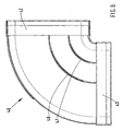
- the horizontal 90 ° flat channel Rolubogen is generally designated 10. At both ends slightly widened connecting flanges 22, 23 are mounted, which allow the flush insertion of the connecting pipes. The actual 90 ° bow is designated 24. Inside this pipe bend, an inner baffle 27 and an outer baffle 26 are arranged, which divide the entire fluid flow, for example, the exhaust air of a kitchen in three sub-streams. The two Leitbteche 26, 27 are guided parallel to the outer wall 25 and the inner wall 29 and extend from a transverse surface 24 to the opposite, here the lower transverse surface 44th
- connection lines together with the connection profile of the inner and the outer wall of the pipe bend including the connecting flanges 22, 23 are designated by 28, the corresponding connection lines of the inner guide elements are designated by 31.
- FIG. 2 shows the connection profile 28 of the inner curved wall 29 and the outer curved wall 25 as an enlargement of the part marked X in FIG. From this it follows that one, arranged here below, cutting edge or connecting edge is substantially straight, but is tapered towards the inside of the pipe bend, while the corresponding cutting edge of, arranged here above, the second section of the pipe bend outside of the lower part to a small area along this edge and extends outside of it. In this way, a simple defined and easy to be accomplished joining of the two sections of the pipe bend is possible. By Welding or bonding, a teste and fluid-tight connection of the two sections is guaranteed.
- Figure 3 shows an enlarged view of the designated in Figure 1 with F-F sectional view in magnification.
- a kind of tongue and groove connection is used to connect the two sections of the guide elements.
- the lower outwardly chamfered cut edge is extended outward like a hook and engages with a correspondingly adapted in reverse manner counter strip 33.
- the resulting grid connection can also be stably connected and sealed by welding or gluing.
- FIG. 4 shows the horizontal 90 ° flat-duct pipe bend shown in FIG. 1 as an exploded view with the two sections shown above one another.
- the same parts are provided with the same reference numerals.
- the upper portion is generally designated 20, the lower portion generally 40. Accordingly, the lower sections are also designated separately, the connection Operatlansche the lower portion with 42. 43.
- the lower flat bottom portion is denoted by 44, the cutting edges of the lower portion of the guide elements with 46, 47 denotes. On these cut edges are shown in a section thinner connecting springs 49 in a section Z, which are beveled flat in the direction of one end of the pipe bend; these come into engagement with corresponding grooves in the upper part of the pipe bend, whereby a simple and - by welding or gluing - stable and fluid-tight connection is made possible.
- FIG. 4 in the lower part of the outer connecting bar 48 of the lower portion is shown, in which engages the straight edge of the upper portion of the pipe bend 10 in principle.
- FIG. 4 also shows an outer chamfer 51 of the connecting flanges 42, 43, 22 towards the end edges, for facilitating the connection, for improving the seal, for better mechanical adaptation and thus also for noise reduction.
- Figure 4a shows the detail "Z" of Figure 4 enlarged, with bevels of an edge of the spring profiles are visible, which correspond to a corresponding Nutverlauf.
- Figure 5 shows the two halves of the pipe bend of Figure 1 and Figure 4 with a small distance from each other, wherein the mutual tongue and groove engaging members 49,50 are shown.
- Figure 5a shows an enlarged view of the one side oblique narrow connecting springs 49 of the lower portion 40 of the pipe bend 10 which reach with corresponding springs 50 of the upper portion 20 in tight engagement.
- Figure 6 shows the lower portion 40 of the pipe bend 10, but exactly from above, to show the exact course of the guide elements parallel to the curved inner wall 29 and the curved outer wall 25.
- FIG. 7 shows another form of a pipe bend, namely a vertical 90 ° flat-channel pipe bend, which is however set up for the sake of clarity and thus practically represents a horizontal pipe bend.
- This pipe bend is generally designated 60. It has a single guide element 62, which is arranged parallel to the curved inner wall 63 and the curved outer wall 65 and substantially centrally.
- the two slightly enlarged connecting flanges are designated 77, 79.
- Figure 8 shows the lower portion of the pipe bend completely shown in Figure 7.
- the forward arrow-shaped beveled connecting springs are denoted by 69, furthermore, the outer adjustment and connection bar 68 is also visible for receiving the straight cut edge of the upper section in principle.
- Figure 9 shows a further embodiment of the invention in the form of a deflection piece 80 between a flat channel and a circular channel to allow a connection between flat channels and round channels.
- the narrower edge 90 of the inner guide element 88 in this case engages slightly in the flange portion 92 of the circular connection piece, which is designed for the sliding over a round duct fitting.
- These guide elements are thus somewhat more expensive to manufacture, but allow a waiver of a two-part production of the pipe bends.
- this different type of technology can be used in all possible pipe bends and not only in the deflector shown.
- FIG. 10 shows the complete connection piece 80.
- the flat channel 82 is arranged vertically and the circular channel 84 horizontally. Well visible are the outer baffle 86 and the inner baffle 84.
- the exit width of the central channel is about 20 percent wider than the other two channels. The same applies to the area of the flat channel.
- FIG. 11 shows the cross section through the diverter pipe bend of FIG. 10.
- outer wall 92 outer guide plate 86
- inner guide plate 88 which projects slightly into the flange region of the round connection 84.
- the curved outer surface 92 describes, starting from the circular channel connection, substantially initially a circular arc with a large radius and then goes over in a flat surface in the direction of the flat channel connection.
- the outer guide element 86 and the inner guide element 88 have essentially the shape of an ellipse.
- the channel widths of the flat-channel connection and the round-channel connection are in the same relationship to each other.
Landscapes
- Engineering & Computer Science (AREA)
- Physics & Mathematics (AREA)
- Fluid Mechanics (AREA)
- Mechanical Engineering (AREA)
- General Engineering & Computer Science (AREA)
- Branch Pipes, Bends, And The Like (AREA)
- Pipe Accessories (AREA)
- Rigid Pipes And Flexible Pipes (AREA)
- Quick-Acting Or Multi-Walled Pipe Joints (AREA)
- Duct Arrangements (AREA)
Abstract
Description
- Die Erfindung bezieht sich auf einen Rohrbogen für Fluidkanäle gemäß dem Oberbegriff des Anspruches 1.
- Derartige Rohrbögen sind ein wesentliches Element von Fluidkanälen, die vermehrt in Gebäuden aller Art für die Belüftung, für die Entlüftung, für Klimaanlagen eingesetzt werden. Prinzipiell ist die Anwendung bei allen Fluiden, Flüssigkeit und Gasen möglich, auch für Erdgasleitung oder für Ölleitungen.
- Eine bevorzugte Anwendung sind Zuluft- und insbesondere Abluftkanäle für Abzugshauben in modernen tauchen.
- Fluidkanäle haben einen bestimmten Leitungswiderstand, der zu Druckverlusten führt, sie benötigen bestimmte Querschnitte und Antriebsmotoren für den Transport, wie für Ventilatoren; diese können mit hohen Geräuschen verbunden sein.
- Ziel der Erfindung ist, den Druckverlust durch den Leitungswiderstand, und damit den Leistungsquerschnitt zu verringern, oder die Durchflussmenge zu erhöhen, gleichzeitig den Geräuschpegel und auch die für den Fluidtransport erforderliche Motorleistung zu verringern.
- Dieses Ziel wird durch die Merkmale des Anspruches 1 gelöst. Weitere Ausgestaltungen der Erfindung sind in den Unteransprüchen unter Schutz gestellt.
- Eine wesentliche Erfindungsidee besteht darin, in den Rohrbögen Leitelemente in ganz bestimmter Weise anzubringen, so dass der Fluidstrom innerhalb des Rohrbogens komplett in mehrere Abschnitte, vorzugsweise zwei oder drei Abschnitte, unterteilt wird, Bisherige Leitelemente in Rohrbögen so in Dubbel, Taschenbuch für den Maschinenbau. Springer-Verlag Berlin. 1970.
DE-Patentschrift 588113 , oderDE-PS 742475 konnten nichts Entscheidendes zu dieser Problemlösung beitragen. - Die erfindungsgemäßen Leitelemente, auch als Leitkörper bezeichnet, verringern die Wirbelbildung und sorgen für gleichmäßigere Geschwindigkeit.
- Die Verbesserungen sind knapp zusammengefasst:
- höhere Strömungsleistung
- - geringerer Energieverbrauch
- weniger Lärm, z. B. an einer Ablufthaube
- - größere mechanische Festigkeit
- - leichtere Montage durch Einführfasen
- kompaktere Abmessungen, insbesondere geringere Höhe.
- Ein Grund, warum sich derartige innere Leitelemente bisher nicht durchsetzen, könnte auch an den relativ schwierigen Herstellungsproblemen liegen. Nachfolgende Ansprüche zeigen unter anderem spezielle Ausführungsformen einer zweiteiligen Herstellung unterschiedlicher Rohrbögen und spezielle Merkmale des Zusammenfügens dieser zweiteiligen Rohrbögen, sowie vorteilhafte Ausgestaltungen und Anordnungen der Leitelemente und der Endkanten der Anschlussflansche. Dadurch ist zum einen ein sehr rasches einfaches und präzises Zusammenfügen möglich, zum anderen wird das Strömungsprofil im Inneren der Rohrbögen praktisch nicht beeinflusst, und weiterhin wird für einen festen Halt der beiden miteinander verbundenen Hälften der Rohrbögen gesorgt.
- Die Erfindung lässt sich auf jede Art von Rohrbögen anwenden, beispielsweise sind drei verschiedene Rohrbögen angeführt, und beispielsweise sind ein oder zwei Leitelemente innerhalb dieser Rohrbögen angeführt. Je nach Rohrbogen sind die Abschnitte der Strömungs-Leitelemente unterschiedlich. Derartige Rohrbögen können auch als Umlenkstücke zwischen verschiedenen Rohrquerschnitten, beispielsweise Flach-Rund, ausgebildet sein. Alle Winkel von Rohrbögen sind möglich, je spitzer der Winkel, umso bedeutsamer wirkt sich die Erfindung aus; am häufigsten sind 90°-Winkel.
- Ausführungsbeispiele der Erfindung sind in der Zeichnung dargestellt.
- Es zeigt:
- Figur 1 einen horizontal angeordneten Flachkanal-Rohrbogen von 90°.
- Figur 2 ein Detail der Zusammenfügung der zwei Hälften des Rohrbogens an der Außenwand und an der Innenwand in vergrößerter Darstellung des Bereiches X von Figur 1,
- Figur 3 in vergrößerter Darstellung ein Detail des Zusammenfügens der beiden Rohrbogen-Hälften in einem vergrößerten Schnitt der Schnittfläche F-F von Figur 1,
- Figur 4 eine Explosions-Darstellung des in Figur 1 gezeigten horizontalen Rohrbogens,
- Figur 4 a das Detail "Z" von Figur 4 vergrößert,
- Figur 5 die beiden Hälften des in Figur 1 dargestellten Rohrbogens mit kleinem Abstand zueinander.
- Figur 5a die Einzelheit Z von Figur 4 in Form von als Eingriffsfeder ausgebildeten Teilbereichen des unteren Teilstückes des Rohrbogens von Figur 4. der mit entsprechenden Nuten des oberen Teilbereiches des horizontalen Rohrbogens von Figur 4 in Eingriff gelangt,
- Figur 6 eine Draufsicht auf den unteren Abschnitt des horizontalen Rohrbogens von Figur 4,
- Figur 7 den der Anschaulichkeit halber aufgestellten vertikalen Flachkanal-Rohrbogen mit einem zentralen Leitelement und einigen an die Innenkante des Leitelementes aufgesetzten Federelementen für den Eingriff in entsprechende Nuten der anderen Rohrbogenhälfte,
- Figur 8 den unteren Abschnitt des in Figur 7 dargestellten Rohrbogens,
- Figur 9 ein anderes Ausführungsbeispiel der Erfindung in Form eines Umlenkstückes zwischen vertikalem Flachkanal und kreisrundem Kanal in perspektivischer Explosionsdarstellung.
- Figur 10 das Umlenkstück von Figur 9 perspektivisch im zusammengebauten Zustand, wobei auch die unterschiedtichen Kanalbreiten sichtbar werden,
- Figur 11 den Querschnitt durch das Umlenkstück von Figur 10 entlang der Schnittlinie A-A.
- In der Zeichnung sind gleiche Teile mit gleichen Bezugszeichen versehen, jedoch nur innerhalb des gleichen Ausführungsbeispieles.
- In Figur 1 ist der horizontale 90°-Flachkanal-Rolubogen allgemein mit 10 bezeichnet. An beiden Enden sind geringfügig erweiterte Anschlussflansche 22, 23 angebracht, welche das bündige Einschieben der Anschlussrohre ermöglichen. Der eigentliche 90°-Rohrbogen ist mit 24 bezeichnet. Im Inneren dieses Rohrbogens sind ein inneres Leitblech 27 und ein äußeres Leitblech 26 angeordnet, die den gesamten Fluidstrom, beispielsweise die Abluft einer Küche, in drei Teilströme aufteilen. Die beiden Leitbteche 26, 27 sind parallel zur Außenwand 25 sowie zur Innenwand 29 geführt und reichen von einer Querfläche 24 bis zur gegenüberliegenden, hier der unteren Querfläche 44.
- Aus Figur 1 ist auch die zweistückige Zusammensetzung des horizontalen hlachkanal-Rohrbogens 10 sichtbar. Die entsprechenden Anschlusslinien nebst Anschlussprofil der inneren und der äußeren Wand des Rohrbogens einschließlich der Anschlussflansche 22, 23 sind mit 28 bezeichnet, die entsprechenden Anschlusslinien der innen angeordneten Leitelemente sind mit 31 bezeichnet.
- Figur 2 zeigt das Anschlussprofil 28 der inneren gekrümmten Wand 29 und der äußeren gekrümmten Wand 25 als Vergrößerung des in Figur 1 mit X bezeichneten Teiles. Hieraus geht hervor, dass eine, hier unten angeordnete, Schnittkante beziehungsweise Anschlusskante im Wesentlichen gerade ausgebildet ist, allerdings zum Inneren des Rohrbogens hin abgeschrägt ist, während die entsprechende Schnittkante des, hier oben angeordneten, zweiten Teilstückes des Rohrbogens sich außerhalb des unteren Teilstückes um einen kleinen Bereich entlang dieser Kante und außerhalb derselben erstreckt. Auf diese Weise ist eine einfache definierte und leicht zu bewerkstelligende Zusammenfügung der beiden Teilstücke des Rohrbogens möglich. Durch Verschweißung oder Verklebung, ist eine teste und fluiddichte Verbindung der beiden Teilstücke gewährleistet.
- Figur 3 zeigt in vergrößerter Darstellung die in Figur 1 mit F-F bezeichnete SchnittDarstellung in Vergrößerung. Hier wird zur Verbindung der beiden Teilstücke der Leitelemente eine Art Nut- und Federverbindung angewandt. Hierbei ist die untere nach außen abgeschrägte Schnittkante nach außen hakenartig verlängert und gelangt in Eingriff mit einer entsprechend in umgekehrter Weise angepassten Gegenleiste 33. Die so entstehende Rasterverbindung kann auch durch Verschweißen oder Verkleben stabil verbunden und abgedichtet werden.
- Figur 4 zeigt den in Figur 1 dargestellten horizontalen 90°-Flachkanal-Rohrbogen als Explosionsdarstellung mit den zwei übereinander dargestellten Teilstücken. Hierbei sind gleiche Teile mit gleichen Bezugszeichen versehen.
- Der Übersicht halber ist das obere Teilstück allgemein mit 20, das untere Teilstück allgemein mit 40 bezeichnet. Dementsprechend sind auch die unteren Teilstücke getrennt bezeichnet, die Anschluss-Teiltlansche des unteren Teilstückes mit 42. 43. Der untere flache Bodenabschnitt ist mit 44 bezeichnet, die Schnittkanten des unteren Teilstückes der Leitelemente mit 46, 47 bezeichnet. Auf diesen Schnittkanten sind in einem Abschnitt dünnere Verbindungs-Federn 49 in einem Abschnitt Z dargestellt, die in Richtung eines Endes des Rohrbogens flach abgeschrägt sind; diese gelangen mit entsprechenden Nuten im oberen Teilstück des Rohrbogens in festem Eingriff, wodurch ein einfaches und - mittels Verschweißen oder Verkleben - stabiles und fluiddichtes Verbinden ermöglicht wird.
- Weiterhin ist in Figur 4 im unteren Teil die äußere Verbindungsleiste 48 des unteren Teilstückes dargestellt, in welche die im Prinzip gerade Kante des oberen Teilstückes des Rohrbogens 10 eingreift. Aus Figur 4 ist auch eine äußere Abschrägung 51 der Anschlussflansche 42, 43, 22 zu den Endkanten hin, zum Erleichtern der Verbindung, zur Verbesserung der Abdichtung, zur besseren mechanischen Anpassung und damit ebenfalls zur Geräusch-Reduzierung zu erkennen.
- Figur 4 a zeigt das Detail "Z" von Figur 4 vergrößert, wobei Abschrägungen einer Kante der Federprofile sichtbar sind, die einen entsprechenden Nutverlauf entsprechen.
- Figur 5 zeigt die beiden Hälften des Rohrbogens von Figur 1 und Figur 4 mit kleinem Abstand zueinander, wobei auch die gegenseitigen Nut- und Feder- Eingriffsglieder 49,50 dargestellt sind.
- Figur 5a zeigt in vergrößerter Darstellung die nach einer Seite abgeschrägten schmalen Verbindungsfedern 49 des unteren Teilstückes 40 des Rohrbogens 10. die mit entsprechenden Federn 50 des oberen Teilstückes 20 in festen Eingriff gelangen.
- Figur 6 zeigt das untere Teilstück 40 des Rohrbogens 10, jedoch genau von oben, um den genauen Verlauf der Leitelemente parallel zur gekrümmten Innenwand 29 und zur gekrümmten Außenwand 25 zu zeigen.
- Figur 7 zeigt eine andere Form eines Rohrbogens, nämlich einen vertikalen 90°-Flachkanal-Rohrbogen, der allerdings der Anschaulichkeit halber aufgestellt ist und somit praktisch ein Horizontalrohrbogen darstellt. Dieser Rohrbogen ist allgemein mit 60 bezeichnet. Er weist ein einziges Leitelement 62 auf, das parallel zur gekrümmten Innenwand 63 und zur gekrümmten Außenwand 65 und im wesentlichen mittig angeordnet ist. Die beiden geringfügig erweiterten Anschlussflansche sind mit 77, 79 bezeichnet.
- Figur 8 zeigt das untere Teilstück des in Figur 7 komplett dargestellten Rohrbogens. Hierbei sind die nach vorne pfeilförmig abgeschrägten Verbindungsfedern mit 69 bezeichnet, weiterhin ist auch die äußere Justier- und Verbindungsleiste 68 zur Aufnahme der im Prinzip geraden Schnittkante des oberen Teilstückes sichtbar.
- Figur 9 zeigt ein weiteres Ausführungsbeispiel der Erfindung in Form eines Umlenkstückes 80 zwischen einem Flachkanal und einem kreisrunden Kanal, um eine Verbindung zwischen Flachkanälen und Rundkanälen zu ermöglichen.
- Bei diesem besonderen Ausführungsbeispiel gibt es einige konstruktive Besonderheiten. So sind hier die beiden, zueinander parallel geführten Leitelemente nicht parallel zur Innenwand beziehungsweise Außenwand. Um ein gleich großes Durchgangsvolumen für das Fluid aufrecht zu erhalten, ergibt sich auch vom Flachkanal zum Rundkanal eine Verjüngung des Kanalabschnittes. Schließlich ist auch keine Herstellung aus zwei Teilstücken vorgesehen, sondern die Anfertigung von kompletten Einsatzteilen 86, 88 mit Seitenabschnitten 87 beziehungsweise 89. Hierbei sind die zwei vorgesehenen Leitelemente als komplette Bauteile 86. 88 mit Seitenwänden 87 bzw. 89 ausgebildet, die als ganzes in den Rohrbogen eingeschoben und verankert werden. Die Seitenwände dieser Leitelemente und die entsprechenden Außenwände des Umlenk-Rohrbogens sind so gestaltet, dass sie im eingebauten Zustand miteinander bündig sind und somit keinen zusätzlichen Wandwiderstand ergeben. Die schmälere Kante 90 des inneren Leitelementes 88 greift hierbei geringfügig in den Flanschbereich 92des kreisrunden Anschlussstückes ein, der für das Überschieben eines runden Kanal- Anschlussstückes ausgebildet ist. Diese Leitelemente sind somit etwas aufwändiger in der Herstellung, erlauben jedoch einen Verzicht auf eine zweiteilige Herstellung der Rohrbögen. Selbstverständlich ist diese andersartige Technik bei allen möglichen Rohrbögen und nicht nur bei dem gezeigten Umlenkstück einsetzbar.
- Figur 10 zeigt das komplette Anschlussstück 80. wobei der Flachkanal 82 vertikal und der kreisrunde Kanal 84 horizontal angeordnet sind. Gut sichtbar sind das äußere Leitelement 86 und das innere Leitelement 84. Bei diesem Ausführungsbeispiel ist die Austrittsbreite des mittleren Kanales um etwa 20 Prozent breiter als die beiden anderen Kanäle ausgebildet. Ähnliches gilt auch für den Bereich des Flachkanales.
- Figur 11 zeigt den Querschnitt durch den Umlenkstück-Rohrbogen von Figur 10. Hier sind insbesondere die genauen Krümmungen von Außenwandung 92, äußerem Leitblech 86, innerem Leitblech 88, das in den Flanschbereich des Rundanschlusses 84 geringfügig hineinragt.
- Die gekrümmte Außenfläche 92 beschreibt, ausgehend vom kreisrunden Kanalanschluss, im Wesentlichen zunächst einen Kreisbogen mit großem Radius und geht dann in eine ebene Fläche in Richtung zum Flachkanalanschluss über. Das äußere Leitelement 86 und das innere Leitelement 88 haben im Wesentlichen die Form einer Ellipse. Die Kanalbreiten des Flachkanal-Anschlusses und des Rundkanal-Anschlusses stehen hierbei im gleichen Verhältnis zueinander.
Claims (17)
- Rohrbogen für Fluidkanäle mit starren Fluid-Leitelementen,
insbesondere für Zu- und Abluftkanäle, insbesondere für Küchen,
dadurch gekennzeichnet,
dass die Leitelemente (26, 27) parallel zueinander und zu den gekrümmten Innenwänden (29, 63) und Außenwänden (25; 65) geführt sind,
oder dass die Leitelemente bei einem Übergangsstück von Flachkanal zu kreisrundem Kanal (82, 84), ausgehend von einem Flachkanal (82) zu einem kreisrunden Kanal (84) in ein gerades Stück Richtung Flachkanal übergehen, dass das äußere Leitelement (86) und gegebenenfalls, falls vorhanden, ein weiteres inneres Leitelement (88) im wesentlichen eine Ellipsenform aufweisen, und dass die Kanalbreiten des kreisrunden Kanalanschlusses des Flachkanal-Anschlusses proportional zueinander stehen. - Rohrbogen nach Anspruch 1, dadurch gekennzeichnet, dass er aus zwei Teilstücken (20, 40) zusammengefügt ist.
- Rohrbogen nach Anspruch 2, dadurch gekennzeichnet, dass die Schnittkanten (46, 47) der Leitelemente (26, 27) wenigstens abschnittsweise über Federprofile (49, 49, 50, 50) die in gegenüberliegende Nuten des anderen Teilstückes (20, 40) einrastbar sind, und über Abdicht- und Klebemittel oder durch Verschweißen miteinander verbunden sind.
- Rohrbogen nach Anspruch 2 oder Anspruch 3, dadurch gekennzeichnet, dass an einer der einander zugewandten Schnittkanten von Innenwand und Außenwand wenigstens abschnittsweise eine übergreifende Eingriffskante (28) für die im wesentlichen gerade Schnittkante des anderen Teilstückes des Rohrbogens einschließlich der Verbindungslaschen des Rohrbogens angeordnet ist, wobei beide Kanten miteinander abdichtend verklebt oder verschweißt sind.
- Rohrbogen nach Anspruch 4, dadurch gekennzeichnet, dass die beiden Schnittkanten der beiden Teilstücke des Rohrbogens zueinander passend gegenläufig abgeschrägt sind, wobei die gerade Außenkante nach außen abgeschrägt ist.
- Rohrbogen nach Anspruch 5. dadurch gekennzeichnet, dass eine abgeschrägte Schnittkante nach außen verlängert ist, um in Eingriff mit der Eingriffsleiste der anderen Schnittkante zu stehen.
- Rohrbogen nach einem der Ansprüche 1 bis 6, dadurch gekennzeichnet, dass ein vertikaler Flachkanalbogen (60) vorzugsweise von 90°, vorgesehen ist, wobei in seiner Mittellinie symmetrisch ein einziges Leitelement (62) vorgesehen ist.
- Rohrbogen nach einem der Ansprüche 1 bis 6, dadurch gekennzeichnet, dass ein horizontaler Flachkanalbogen, vorzugsweise von 90°, vorgesehen ist, in welchem zwei Leitelemente (26, 27) parallel zueinander und zur gekrümmten Innenwand (29) sowie zur gekrümmten Außenwand (25) vorgesehen ist,
wobei ein äußeres Leitelement (26) etwa in der Mitte des Kanales vorgesehen ist, und ein inneres Leitelement (27) zwischen gekrümmter Innenwand (29) und dem äußeren Leitelement (26) angeordnet ist,
derart, dass die äußere Kanalbreite etwa doppelt so groß wie die Kanalbreite der beiden inneren Kanäle ist. - Rohrbogen nach einem der Ansprüche 1 bis 6, dadurch gekennzeichnet, dass er ein Umlenkstück (80) von einem vertikalen Flachkanal (82) zu einem kreisrunden Kanal (84) ist,
in welchem, vorzugsweise zwei, Leitelemente (86, 88) in gleichen Abständen oder mit einem um etwa 10 bis 30 Prozent breiteren Innenkanal verlaufen. - Rohrbogen nach Anspruch 9, dadurch gekennzeichnet, dass die beiden Leitelemente (86, 88) in etwa elliptisch vom kreisrunden Anschlussstück zum Flachkanalanschlussstück verlaufen, und dass die gekrümmte Außenfläche (92) ebenfalls elliptisch verläuft, oder dass sich an das kreisrunde Anschlussstück (84) erst ein Kreisbogen mit großem Radius anschließt, der dann in Richtung Flachkanal in ein gerades ebenes Stück übergeht.
wobei die Proportionen der Kanalbreiten im kreisrunden Anschlussstück und im Flachkanalanschlussstück im Wesentlichen gleich sind,
und wobei vorzugsweise der Mittelkanal um etwa 10 bis 30 Prozent breiter als die beiden Außenkanäle ist. - Rohrbogen nach einem der Ansprüche 9 oder 10, dadurch gekennzeichnet, dass er einstückig ausgebildet ist,
dass die Leitelemente (86. 88) in den Rohrbogen eingeschoben und mit diesem abdichtend verbunden werden, durch Verschweißen oder Verkleben. - Rohrbogen nach Anspruch 11, dadurch gekennzeichnet, dass die Leitelemente (86, 88) Seitenwände (87, 89) ausweisen, die in entsprechenden Aussparungen (83) an der Innenwand des Rohrbogens, beziehungsweise in sich nach außen erstreckende Ausbuchtungen, derart einführbar und befestigbar sind, dass sich eine ebene Ilnnenfläche des Rohrbogens ergibt.
- Rohrbogen nach einem der Ansprüche 3 bis 12, dadurch gekennzeichnet, dass die Nuten und die zugeordneten Federprofile (49, 50) zur Erleichterung der Herstellung und Montage zu einer Seite hin abgeschrägt sind.
- Rohrbogen nach einem der Ansprüche 3 bis 13, dadurch gekennzeichnet, dass an beiden Schnittkanten (46, 42) Eingriffsnuten vorgesehen sind, die durch ein Federprofil (49, 50) miteinander verbunden sind.
- Rohrbogen nach Anspruch 14, dadurch gekennzeichnet, dass entlang der Schnittkanten (46, 47) der beiden gegenüberliegenden Teilstücke (20, 40) zur Vereinfachung des Zusammenfügens Federprofile (49, 50) und Nuten (46, 47) gegeneinander versetzt sind (Fig. 5 a).
- Rohrbogen nach einem der Ansprüche 4 bis 15, dadurch gekennzeichnet, dass die Abschnitte der übergreifenden Eingriffskanten (28) entlang der Schnittkanten der beiden Teilstücke (20, 40) von Innenwand und Außenwand abwechseln, vorzugsweise über jeweils die halbe Kantenlänge.
- Rohrbogen nach einem der Ansprüche 1 bis 16, dadurch gekennzeichnet, dass die Innenkanten (51) der Anschlussflansche (22, 42, 43) zur Endkante hin zur Verbesserung des Anschlusses, der Dichtigkeit, des Fliesswiderstandes und der Geräuschentwicklung abgeschrägt sind.
Priority Applications (6)
| Application Number | Priority Date | Filing Date | Title |
|---|---|---|---|
| DE502005009215T DE502005009215D1 (de) | 2005-11-16 | 2005-11-16 | Rohrbogen für Fluidkanäle |
| ES05024982.0T ES2543590T5 (es) | 2005-11-16 | 2005-11-16 | Codo para canalizaciones de fluido |
| AT08004098T ATE460588T1 (de) | 2005-11-16 | 2005-11-16 | Rohrbogen für fluidkanäle |
| EP05024982.0A EP1788259B2 (de) | 2005-11-16 | 2005-11-16 | Rohrbogen für Fluidkanäle |
| ES08004098T ES2343388T3 (es) | 2005-11-16 | 2005-11-16 | Codo para conductos de fluido. |
| EP08004098A EP1923576B1 (de) | 2005-11-16 | 2005-11-16 | Rohrbogen für Fluidkanäle |
Applications Claiming Priority (1)
| Application Number | Priority Date | Filing Date | Title |
|---|---|---|---|
| EP05024982.0A EP1788259B2 (de) | 2005-11-16 | 2005-11-16 | Rohrbogen für Fluidkanäle |
Related Child Applications (2)
| Application Number | Title | Priority Date | Filing Date |
|---|---|---|---|
| EP08004098A Division-Into EP1923576B1 (de) | 2005-11-16 | 2005-11-16 | Rohrbogen für Fluidkanäle |
| EP08004098A Division EP1923576B1 (de) | 2005-11-16 | 2005-11-16 | Rohrbogen für Fluidkanäle |
Publications (3)
| Publication Number | Publication Date |
|---|---|
| EP1788259A1 true EP1788259A1 (de) | 2007-05-23 |
| EP1788259B1 EP1788259B1 (de) | 2015-07-22 |
| EP1788259B2 EP1788259B2 (de) | 2018-09-19 |
Family
ID=36177659
Family Applications (2)
| Application Number | Title | Priority Date | Filing Date |
|---|---|---|---|
| EP05024982.0A Expired - Lifetime EP1788259B2 (de) | 2005-11-16 | 2005-11-16 | Rohrbogen für Fluidkanäle |
| EP08004098A Expired - Lifetime EP1923576B1 (de) | 2005-11-16 | 2005-11-16 | Rohrbogen für Fluidkanäle |
Family Applications After (1)
| Application Number | Title | Priority Date | Filing Date |
|---|---|---|---|
| EP08004098A Expired - Lifetime EP1923576B1 (de) | 2005-11-16 | 2005-11-16 | Rohrbogen für Fluidkanäle |
Country Status (4)
| Country | Link |
|---|---|
| EP (2) | EP1788259B2 (de) |
| AT (1) | ATE460588T1 (de) |
| DE (1) | DE502005009215D1 (de) |
| ES (2) | ES2543590T5 (de) |
Cited By (8)
| Publication number | Priority date | Publication date | Assignee | Title |
|---|---|---|---|---|
| CN102155478A (zh) * | 2011-04-28 | 2011-08-17 | 唐力南 | 弯管流速调整器 |
| EP3457014A1 (de) * | 2017-09-14 | 2019-03-20 | Naber Holding GmbH & Co. KG | Flachkanalverbinder für einen flachkanal und eine entsprechende kanalanordnung |
| CZ308916B6 (cs) * | 2020-06-29 | 2021-08-25 | Oil&Gas Metering Equipment S.R.O. | Usměrňovač průtoku plynu v ohybu proudění u ultrazvukového plynoměru |
| US11493057B2 (en) | 2019-12-02 | 2022-11-08 | Carrier Corporation | Centrifugal compressor and method of operating the same |
| CN115370854A (zh) * | 2021-05-21 | 2022-11-22 | 纳贝尔控股有限责任两合公司 | 用于抽油烟机的排气通道的弯管 |
| CN115370855A (zh) * | 2021-05-21 | 2022-11-22 | 纳贝尔控股有限责任两合公司 | 下行气流元件和组件 |
| EP4092340A1 (de) * | 2021-05-21 | 2022-11-23 | Naber Holding GmbH & Co. KG | Rohrbogen für einen abluftkanal einer dunstabzugshaube |
| CN115419616A (zh) * | 2022-09-05 | 2022-12-02 | 江森自控空调冷冻设备(无锡)有限公司 | 离心压缩机的吸气管 |
Families Citing this family (1)
| Publication number | Priority date | Publication date | Assignee | Title |
|---|---|---|---|---|
| DE202021101741U1 (de) | 2021-03-31 | 2021-04-15 | Naber Holding Gmbh & Co. Kg | Flachkanalanordnung für eine Downdraft-Dunstabzugshaube |
Citations (8)
| Publication number | Priority date | Publication date | Assignee | Title |
|---|---|---|---|---|
| DE387935C (de) * | 1922-08-29 | 1924-01-09 | Maschf | Rohrleitung bei Luftfoerderern fuer Schuettgut |
| DE588113C (de) | 1929-01-09 | 1933-11-14 | Hermann Foettinger Dr Ing | Leitflaechenanordnung fuer offene und geschlossene Kanaele |
| GB509287A (en) * | 1938-05-23 | 1939-07-13 | Neu Sa | Improvements relating to apparatus for distributing humidified air |
| DE742475C (de) | 1939-10-29 | 1944-06-02 | Focke Wulf Flugzeugbau G M B H | Rohrkruemmer |
| BE510469A (de) * | 1951-04-08 | 1952-04-30 | Walter Dr-Ing Barth | |
| DE1261715B (de) * | 1965-02-05 | 1968-02-22 | Steinzeug Und Kunststoffwarenf | Kruemmer mit rechteckigem Querschnitt sowie Verfahren und Vorrichtung zur Herstellung desselben |
| US4919170A (en) * | 1987-08-08 | 1990-04-24 | Veba Kraftwerke Ruhr Aktiengesellschaft | Flow duct for the flue gas of a flue gas-cleaning plant |
| DE10360839B3 (de) * | 2003-12-23 | 2005-06-09 | Naber Holding Gmbh & Co. Kg | Rohrkrümmer zum Verbinden von Fluidleitungen |
Family Cites Families (7)
| Publication number | Priority date | Publication date | Assignee | Title |
|---|---|---|---|---|
| DE913600C (de) | 1952-08-17 | 1954-06-18 | Armco Int Corp | Verbindungsanordnung fuer zusammensetzbare Abflussrohre |
| FR2350539A1 (fr) | 1976-05-07 | 1977-12-02 | Saunier Duval | Coude de raccordement pour deux tubes concentriques |
| DE3807688C2 (de) | 1988-03-09 | 1995-04-13 | Horst Severyns | Verfahren und Vorrichtung zur Herstellung eines Kunststoffrohr-Formstücks |
| MX9601490A (es) † | 1995-09-28 | 1997-03-29 | Emhart Inc | Ensamble de conexion de maza. |
| DE59501301D1 (de) | 1995-09-28 | 1998-02-19 | Benteler Werke Ag | Abgaskrümmer |
| DE10227689A1 (de) | 2002-06-21 | 2004-01-08 | Ina-Schaeffler Kg | Linearwälzlager mit geteiltem Rücklaufrohr |
| EP1570926A1 (de) | 2004-03-03 | 2005-09-07 | Manfred Strub | Verfahren zur Herstellung eines Rohrbogens für ein Regenfallrohr, ein Rohrbogenstück und ein Regenfallrohr |
-
2005
- 2005-11-16 ES ES05024982.0T patent/ES2543590T5/es not_active Expired - Lifetime
- 2005-11-16 ES ES08004098T patent/ES2343388T3/es not_active Expired - Lifetime
- 2005-11-16 EP EP05024982.0A patent/EP1788259B2/de not_active Expired - Lifetime
- 2005-11-16 EP EP08004098A patent/EP1923576B1/de not_active Expired - Lifetime
- 2005-11-16 AT AT08004098T patent/ATE460588T1/de active
- 2005-11-16 DE DE502005009215T patent/DE502005009215D1/de not_active Expired - Lifetime
Patent Citations (8)
| Publication number | Priority date | Publication date | Assignee | Title |
|---|---|---|---|---|
| DE387935C (de) * | 1922-08-29 | 1924-01-09 | Maschf | Rohrleitung bei Luftfoerderern fuer Schuettgut |
| DE588113C (de) | 1929-01-09 | 1933-11-14 | Hermann Foettinger Dr Ing | Leitflaechenanordnung fuer offene und geschlossene Kanaele |
| GB509287A (en) * | 1938-05-23 | 1939-07-13 | Neu Sa | Improvements relating to apparatus for distributing humidified air |
| DE742475C (de) | 1939-10-29 | 1944-06-02 | Focke Wulf Flugzeugbau G M B H | Rohrkruemmer |
| BE510469A (de) * | 1951-04-08 | 1952-04-30 | Walter Dr-Ing Barth | |
| DE1261715B (de) * | 1965-02-05 | 1968-02-22 | Steinzeug Und Kunststoffwarenf | Kruemmer mit rechteckigem Querschnitt sowie Verfahren und Vorrichtung zur Herstellung desselben |
| US4919170A (en) * | 1987-08-08 | 1990-04-24 | Veba Kraftwerke Ruhr Aktiengesellschaft | Flow duct for the flue gas of a flue gas-cleaning plant |
| DE10360839B3 (de) * | 2003-12-23 | 2005-06-09 | Naber Holding Gmbh & Co. Kg | Rohrkrümmer zum Verbinden von Fluidleitungen |
Non-Patent Citations (2)
| Title |
|---|
| "BISHERIGE LEITELEMENTE IN ROHRBÖGEN SO IN DUBBEL", 1970, SPRINGER-VERLAG BERLIN |
| 30 September 2005, FABER, XP002378977 * |
Cited By (22)
| Publication number | Priority date | Publication date | Assignee | Title |
|---|---|---|---|---|
| CN102155478A (zh) * | 2011-04-28 | 2011-08-17 | 唐力南 | 弯管流速调整器 |
| EP3457014A1 (de) * | 2017-09-14 | 2019-03-20 | Naber Holding GmbH & Co. KG | Flachkanalverbinder für einen flachkanal und eine entsprechende kanalanordnung |
| US11867196B2 (en) | 2019-12-02 | 2024-01-09 | Carrier Corporation | Centrifugal compressor and method of operating the same |
| US11493057B2 (en) | 2019-12-02 | 2022-11-08 | Carrier Corporation | Centrifugal compressor and method of operating the same |
| JP2022551021A (ja) * | 2020-06-29 | 2022-12-07 | オイル アンド ガス メータリング エクイップメント エス.アール.オー. | 特に超音波ガスメータ用の流れ湾曲部内ガス流れ調整器 |
| KR20220027852A (ko) * | 2020-06-29 | 2022-03-08 | 오일앤가스 미터링 이큅먼트 에스.알.오. | 초음파 가스 계량기용 유량 굴곡부의 가스 유량 조절기 |
| US12196236B2 (en) | 2020-06-29 | 2025-01-14 | Oil&Gasmetering Equipment S.R.O. | Gas flow conditioner in the flow bend, especially for ultrasonic gas meter |
| WO2021229554A1 (en) * | 2020-06-29 | 2021-11-18 | Oil&Gas Metering Equipment S.R.O. | Gas flow conditioner in the flow bend, especially for ultrasonic gas meter |
| CN115380172A (zh) * | 2020-06-29 | 2022-11-22 | 石油和天然气计量设备公司 | 特别适用于超声波气体流量计的流动弯头中的气体流动调整器 |
| CZ308916B6 (cs) * | 2020-06-29 | 2021-08-25 | Oil&Gas Metering Equipment S.R.O. | Usměrňovač průtoku plynu v ohybu proudění u ultrazvukového plynoměru |
| JP7329882B2 (ja) | 2020-06-29 | 2023-08-21 | オイル アンド ガス メータリング エクイップメント エス.アール.オー. | 特に超音波ガスメータ用の流れ湾曲部内ガス流れ調整器 |
| CN115370855A (zh) * | 2021-05-21 | 2022-11-22 | 纳贝尔控股有限责任两合公司 | 下行气流元件和组件 |
| EP4092347A1 (de) * | 2021-05-21 | 2022-11-23 | Naber Holding GmbH & Co. KG | Downdraft-element und anordnung |
| US11841162B2 (en) | 2021-05-21 | 2023-12-12 | Naber Holding GmbH & Co. | Pipe bend for an exhaust air duct of a fume extraction hood |
| EP4092340A1 (de) * | 2021-05-21 | 2022-11-23 | Naber Holding GmbH & Co. KG | Rohrbogen für einen abluftkanal einer dunstabzugshaube |
| US11933333B2 (en) | 2021-05-21 | 2024-03-19 | Naber Holding GmbH & Co. | Downdraft element and assembly |
| CN115370854A (zh) * | 2021-05-21 | 2022-11-22 | 纳贝尔控股有限责任两合公司 | 用于抽油烟机的排气通道的弯管 |
| AU2022202674B2 (en) * | 2021-05-21 | 2025-05-29 | Naber Holding Gmbh & Co. Kg | Pipe bend for an exhaust air duct of a fume-extraction hood |
| CN115370855B (zh) * | 2021-05-21 | 2026-01-30 | 纳贝尔控股有限责任两合公司 | 下行气流元件和组件 |
| CN115419616A (zh) * | 2022-09-05 | 2022-12-02 | 江森自控空调冷冻设备(无锡)有限公司 | 离心压缩机的吸气管 |
| WO2024051608A1 (zh) * | 2022-09-05 | 2024-03-14 | 江森自控空调冷冻设备(无锡)有限公司 | 离心压缩机的吸气管 |
| CN115419616B (zh) * | 2022-09-05 | 2025-10-24 | 江森自控空调冷冻设备(无锡)有限公司 | 离心压缩机的吸气管 |
Also Published As
| Publication number | Publication date |
|---|---|
| ES2543590T5 (es) | 2018-11-02 |
| ES2543590T3 (es) | 2015-08-20 |
| DE502005009215D1 (de) | 2010-04-22 |
| EP1788259B1 (de) | 2015-07-22 |
| ATE460588T1 (de) | 2010-03-15 |
| EP1923576B1 (de) | 2010-03-10 |
| EP1788259B2 (de) | 2018-09-19 |
| EP1923576A1 (de) | 2008-05-21 |
| ES2343388T3 (es) | 2010-07-29 |
Similar Documents
| Publication | Publication Date | Title |
|---|---|---|
| EP4229245B1 (de) | Verwendung eines schlauchs zur fluidischen verbindung eines auslaufstücks mit einem ventil an einer sanitärarmatur, fluidische anordnung und korrespondierende sanitärarmatur | |
| DE202005017821U1 (de) | Rohrbogen für Fluidkanäle | |
| DE202016106030U1 (de) | Scheibenventil mit reduziertem Differenzdruck | |
| DE3440489A1 (de) | Kuehler, insbesondere fuer die kuehlanlage eines verbrennungsmotors eines kraftfahrzeuges | |
| EP1788259B1 (de) | Rohrbogen für Fluidkanäle | |
| DE102020127375A1 (de) | Verwendung eines Schlauchs zur fluidischen Verbindung eines Auslaufstücks mit einem Ventil an einer Sanitärarmatur, fluidische Anordnung und korrespondierende Sanitärarmatur | |
| DE3125368A1 (de) | Rohrstutzen, insbesondere zur verbindung eines waermetauschers mit einem heizkreis | |
| EP0047467B1 (de) | Stossverbindung für Kanalabschnitte aus Blech, insbes. Kanalabschnitte für Lüftungsanlagen | |
| EP2928619B1 (de) | Spülschlauchgelenk, spülschlauchdrehvorrichtung und spüldüse | |
| AT8708U1 (de) | Rohrbogen für fluidkanäle | |
| DE102018113818B4 (de) | Dunstabzugssystem | |
| EP0607166B1 (de) | Vorrichtung zum ansaugen von zusatzstoffen in eine fluidströmung | |
| DE3326592C2 (de) | ||
| DE102007043272B4 (de) | Einsatz für eine Sanitärarmatur | |
| DE102012011943B4 (de) | Volumenstromregler mit einer Venturidüseneinheit, insbesondere aus Kunststoff | |
| DE9100867U1 (de) | Abgasrohrleitung für einen Verbrennungsmotor, insbesondere eines Kraftfahrzeugs | |
| DE29808031U1 (de) | Paneel- bzw. Flachheizkörper | |
| EP0951625B1 (de) | Formstück zur Fluid-Strömungsumlenkung | |
| EP1860364A1 (de) | Rohrleitungsanschlussstück | |
| EP4678989A1 (de) | Luftanschlussstutzen für ein lüftungsgerät, entsprechendes lüftungsgerät sowie verfahren zum montieren eines lüftungsgeräts | |
| DE19608016C2 (de) | Sperrelement für einen Strömungskanal | |
| DE102010020646A1 (de) | Luftklappenvorrichtung zum Einstellen eines Volumenstroms | |
| DE9101646U1 (de) | Verbindungsbogen | |
| DE102021203900A1 (de) | Ein- oder mehrreihiger Heizkörper | |
| DE2757060B2 (de) | Abluftleitvorrichtung |
Legal Events
| Date | Code | Title | Description |
|---|---|---|---|
| PUAI | Public reference made under article 153(3) epc to a published international application that has entered the european phase |
Free format text: ORIGINAL CODE: 0009012 |
|
| AK | Designated contracting states |
Kind code of ref document: A1 Designated state(s): AT BE BG CH CY CZ DE DK EE ES FI FR GB GR HU IE IS IT LI LT LU LV MC NL PL PT RO SE SI SK TR |
|
| AX | Request for extension of the european patent |
Extension state: AL BA HR MK YU |
|
| 17P | Request for examination filed |
Effective date: 20071122 |
|
| 17Q | First examination report despatched |
Effective date: 20071228 |
|
| AKX | Designation fees paid |
Designated state(s): AT BE BG CH CY CZ DE DK EE ES FI FR GB GR HU IE IS IT LI LT LU LV MC NL PL PT RO SE SI SK TR |
|
| GRAP | Despatch of communication of intention to grant a patent |
Free format text: ORIGINAL CODE: EPIDOSNIGR1 |
|
| INTG | Intention to grant announced |
Effective date: 20150302 |
|
| GRAS | Grant fee paid |
Free format text: ORIGINAL CODE: EPIDOSNIGR3 |
|
| GRAA | (expected) grant |
Free format text: ORIGINAL CODE: 0009210 |
|
| AK | Designated contracting states |
Kind code of ref document: B1 Designated state(s): AT BE BG CH CY CZ DE DK EE ES FI FR GB GR HU IE IS IT LI LT LU LV MC NL PL PT RO SE SI SK TR |
|
| REG | Reference to a national code |
Ref country code: GB Ref legal event code: FG4D Free format text: NOT ENGLISH |
|
| REG | Reference to a national code |
Ref country code: CH Ref legal event code: EP |
|
| REG | Reference to a national code |
Ref country code: IE Ref legal event code: FG4D Free format text: LANGUAGE OF EP DOCUMENT: GERMAN |
|
| REG | Reference to a national code |
Ref country code: AT Ref legal event code: REF Ref document number: 738099 Country of ref document: AT Kind code of ref document: T Effective date: 20150815 |
|
| REG | Reference to a national code |
Ref country code: ES Ref legal event code: FG2A Ref document number: 2543590 Country of ref document: ES Kind code of ref document: T3 Effective date: 20150820 |
|
| REG | Reference to a national code |
Ref country code: DE Ref legal event code: R096 Ref document number: 502005014862 Country of ref document: DE |
|
| REG | Reference to a national code |
Ref country code: FR Ref legal event code: PLFP Year of fee payment: 11 |
|
| REG | Reference to a national code |
Ref country code: NL Ref legal event code: FP |
|
| REG | Reference to a national code |
Ref country code: LT Ref legal event code: MG4D |
|
| PG25 | Lapsed in a contracting state [announced via postgrant information from national office to epo] |
Ref country code: GR Free format text: LAPSE BECAUSE OF FAILURE TO SUBMIT A TRANSLATION OF THE DESCRIPTION OR TO PAY THE FEE WITHIN THE PRESCRIBED TIME-LIMIT Effective date: 20151023 Ref country code: LT Free format text: LAPSE BECAUSE OF FAILURE TO SUBMIT A TRANSLATION OF THE DESCRIPTION OR TO PAY THE FEE WITHIN THE PRESCRIBED TIME-LIMIT Effective date: 20150722 Ref country code: FI Free format text: LAPSE BECAUSE OF FAILURE TO SUBMIT A TRANSLATION OF THE DESCRIPTION OR TO PAY THE FEE WITHIN THE PRESCRIBED TIME-LIMIT Effective date: 20150722 Ref country code: LV Free format text: LAPSE BECAUSE OF FAILURE TO SUBMIT A TRANSLATION OF THE DESCRIPTION OR TO PAY THE FEE WITHIN THE PRESCRIBED TIME-LIMIT Effective date: 20150722 |
|
| PG25 | Lapsed in a contracting state [announced via postgrant information from national office to epo] |
Ref country code: SE Free format text: LAPSE BECAUSE OF FAILURE TO SUBMIT A TRANSLATION OF THE DESCRIPTION OR TO PAY THE FEE WITHIN THE PRESCRIBED TIME-LIMIT Effective date: 20150722 Ref country code: PT Free format text: LAPSE BECAUSE OF FAILURE TO SUBMIT A TRANSLATION OF THE DESCRIPTION OR TO PAY THE FEE WITHIN THE PRESCRIBED TIME-LIMIT Effective date: 20151123 Ref country code: PL Free format text: LAPSE BECAUSE OF FAILURE TO SUBMIT A TRANSLATION OF THE DESCRIPTION OR TO PAY THE FEE WITHIN THE PRESCRIBED TIME-LIMIT Effective date: 20150722 Ref country code: IS Free format text: LAPSE BECAUSE OF FAILURE TO SUBMIT A TRANSLATION OF THE DESCRIPTION OR TO PAY THE FEE WITHIN THE PRESCRIBED TIME-LIMIT Effective date: 20151122 |
|
| REG | Reference to a national code |
Ref country code: DE Ref legal event code: R026 Ref document number: 502005014862 Country of ref document: DE |
|
| PG25 | Lapsed in a contracting state [announced via postgrant information from national office to epo] |
Ref country code: CZ Free format text: LAPSE BECAUSE OF FAILURE TO SUBMIT A TRANSLATION OF THE DESCRIPTION OR TO PAY THE FEE WITHIN THE PRESCRIBED TIME-LIMIT Effective date: 20150722 Ref country code: EE Free format text: LAPSE BECAUSE OF FAILURE TO SUBMIT A TRANSLATION OF THE DESCRIPTION OR TO PAY THE FEE WITHIN THE PRESCRIBED TIME-LIMIT Effective date: 20150722 Ref country code: SK Free format text: LAPSE BECAUSE OF FAILURE TO SUBMIT A TRANSLATION OF THE DESCRIPTION OR TO PAY THE FEE WITHIN THE PRESCRIBED TIME-LIMIT Effective date: 20150722 Ref country code: DK Free format text: LAPSE BECAUSE OF FAILURE TO SUBMIT A TRANSLATION OF THE DESCRIPTION OR TO PAY THE FEE WITHIN THE PRESCRIBED TIME-LIMIT Effective date: 20150722 |
|
| PLBI | Opposition filed |
Free format text: ORIGINAL CODE: 0009260 |
|
| PG25 | Lapsed in a contracting state [announced via postgrant information from national office to epo] |
Ref country code: RO Free format text: LAPSE BECAUSE OF FAILURE TO SUBMIT A TRANSLATION OF THE DESCRIPTION OR TO PAY THE FEE WITHIN THE PRESCRIBED TIME-LIMIT Effective date: 20150722 |
|
| PLAX | Notice of opposition and request to file observation + time limit sent |
Free format text: ORIGINAL CODE: EPIDOSNOBS2 |
|
| 26 | Opposition filed |
Opponent name: SCHURACK, EDUARD Effective date: 20160422 |
|
| PG25 | Lapsed in a contracting state [announced via postgrant information from national office to epo] |
Ref country code: MC Free format text: LAPSE BECAUSE OF FAILURE TO SUBMIT A TRANSLATION OF THE DESCRIPTION OR TO PAY THE FEE WITHIN THE PRESCRIBED TIME-LIMIT Effective date: 20150722 Ref country code: LU Free format text: LAPSE BECAUSE OF FAILURE TO SUBMIT A TRANSLATION OF THE DESCRIPTION OR TO PAY THE FEE WITHIN THE PRESCRIBED TIME-LIMIT Effective date: 20151116 |
|
| REG | Reference to a national code |
Ref country code: CH Ref legal event code: PL |
|
| PG25 | Lapsed in a contracting state [announced via postgrant information from national office to epo] |
Ref country code: LI Free format text: LAPSE BECAUSE OF NON-PAYMENT OF DUE FEES Effective date: 20151130 Ref country code: CH Free format text: LAPSE BECAUSE OF NON-PAYMENT OF DUE FEES Effective date: 20151130 |
|
| REG | Reference to a national code |
Ref country code: IE Ref legal event code: MM4A |
|
| PG25 | Lapsed in a contracting state [announced via postgrant information from national office to epo] |
Ref country code: SI Free format text: LAPSE BECAUSE OF FAILURE TO SUBMIT A TRANSLATION OF THE DESCRIPTION OR TO PAY THE FEE WITHIN THE PRESCRIBED TIME-LIMIT Effective date: 20150722 |
|
| PLBB | Reply of patent proprietor to notice(s) of opposition received |
Free format text: ORIGINAL CODE: EPIDOSNOBS3 |
|
| REG | Reference to a national code |
Ref country code: FR Ref legal event code: PLFP Year of fee payment: 12 |
|
| PG25 | Lapsed in a contracting state [announced via postgrant information from national office to epo] |
Ref country code: IE Free format text: LAPSE BECAUSE OF NON-PAYMENT OF DUE FEES Effective date: 20151116 |
|
| PG25 | Lapsed in a contracting state [announced via postgrant information from national office to epo] |
Ref country code: HU Free format text: LAPSE BECAUSE OF FAILURE TO SUBMIT A TRANSLATION OF THE DESCRIPTION OR TO PAY THE FEE WITHIN THE PRESCRIBED TIME-LIMIT; INVALID AB INITIO Effective date: 20051116 |
|
| PG25 | Lapsed in a contracting state [announced via postgrant information from national office to epo] |
Ref country code: CY Free format text: LAPSE BECAUSE OF FAILURE TO SUBMIT A TRANSLATION OF THE DESCRIPTION OR TO PAY THE FEE WITHIN THE PRESCRIBED TIME-LIMIT Effective date: 20150722 |
|
| PG25 | Lapsed in a contracting state [announced via postgrant information from national office to epo] |
Ref country code: TR Free format text: LAPSE BECAUSE OF FAILURE TO SUBMIT A TRANSLATION OF THE DESCRIPTION OR TO PAY THE FEE WITHIN THE PRESCRIBED TIME-LIMIT Effective date: 20150722 |
|
| REG | Reference to a national code |
Ref country code: FR Ref legal event code: PLFP Year of fee payment: 13 |
|
| PUAH | Patent maintained in amended form |
Free format text: ORIGINAL CODE: 0009272 |
|
| STAA | Information on the status of an ep patent application or granted ep patent |
Free format text: STATUS: PATENT MAINTAINED AS AMENDED |
|
| 27A | Patent maintained in amended form |
Effective date: 20180919 |
|
| AK | Designated contracting states |
Kind code of ref document: B2 Designated state(s): AT BE BG CH CY CZ DE DK EE ES FI FR GB GR HU IE IS IT LI LT LU LV MC NL PL PT RO SE SI SK TR |
|
| REG | Reference to a national code |
Ref country code: DE Ref legal event code: R102 Ref document number: 502005014862 Country of ref document: DE |
|
| REG | Reference to a national code |
Ref country code: FR Ref legal event code: PLFP Year of fee payment: 14 |
|
| REG | Reference to a national code |
Ref country code: ES Ref legal event code: DC2A Ref document number: 2543590 Country of ref document: ES Kind code of ref document: T5 Effective date: 20181102 |
|
| REG | Reference to a national code |
Ref country code: NL Ref legal event code: FP |
|
| P01 | Opt-out of the competence of the unified patent court (upc) registered |
Effective date: 20230313 |
|
| PGFP | Annual fee paid to national office [announced via postgrant information from national office to epo] |
Ref country code: NL Payment date: 20241126 Year of fee payment: 20 |
|
| PGFP | Annual fee paid to national office [announced via postgrant information from national office to epo] |
Ref country code: DE Payment date: 20241128 Year of fee payment: 20 |
|
| PGFP | Annual fee paid to national office [announced via postgrant information from national office to epo] |
Ref country code: BE Payment date: 20241126 Year of fee payment: 20 |
|
| PGFP | Annual fee paid to national office [announced via postgrant information from national office to epo] |
Ref country code: GB Payment date: 20241126 Year of fee payment: 20 |
|
| PGFP | Annual fee paid to national office [announced via postgrant information from national office to epo] |
Ref country code: FR Payment date: 20241126 Year of fee payment: 20 Ref country code: BG Payment date: 20241127 Year of fee payment: 20 |
|
| PGFP | Annual fee paid to national office [announced via postgrant information from national office to epo] |
Ref country code: AT Payment date: 20241119 Year of fee payment: 20 |
|
| PGFP | Annual fee paid to national office [announced via postgrant information from national office to epo] |
Ref country code: IT Payment date: 20241125 Year of fee payment: 20 Ref country code: ES Payment date: 20241218 Year of fee payment: 20 |
|
| REG | Reference to a national code |
Ref country code: DE Ref legal event code: R071 Ref document number: 502005014862 Country of ref document: DE |
|
| REG | Reference to a national code |
Ref country code: NL Ref legal event code: MK Effective date: 20251115 |
|
| REG | Reference to a national code |
Ref country code: ES Ref legal event code: FD2A Effective date: 20251201 |
|
| REG | Reference to a national code |
Ref country code: GB Ref legal event code: PE20 Expiry date: 20251115 |
|
| REG | Reference to a national code |
Ref country code: BE Ref legal event code: MK Effective date: 20251116 |
|
| REG | Reference to a national code |
Ref country code: AT Ref legal event code: MK07 Ref document number: 738099 Country of ref document: AT Kind code of ref document: T Effective date: 20251116 |
|
| PG25 | Lapsed in a contracting state [announced via postgrant information from national office to epo] |
Ref country code: ES Free format text: LAPSE BECAUSE OF EXPIRATION OF PROTECTION Effective date: 20251117 |