EP1788234A1 - Injecteur de carburant, notamment piezoelectrique, d'un moteur a combustion interne a injection directe - Google Patents
Injecteur de carburant, notamment piezoelectrique, d'un moteur a combustion interne a injection directe Download PDFInfo
- Publication number
- EP1788234A1 EP1788234A1 EP06301156A EP06301156A EP1788234A1 EP 1788234 A1 EP1788234 A1 EP 1788234A1 EP 06301156 A EP06301156 A EP 06301156A EP 06301156 A EP06301156 A EP 06301156A EP 1788234 A1 EP1788234 A1 EP 1788234A1
- Authority
- EP
- European Patent Office
- Prior art keywords
- injector
- flange
- injector body
- yoke
- internal combustion
- Prior art date
- Legal status (The legal status is an assumption and is not a legal conclusion. Google has not performed a legal analysis and makes no representation as to the accuracy of the status listed.)
- Withdrawn
Links
Images

Classifications
-
- F—MECHANICAL ENGINEERING; LIGHTING; HEATING; WEAPONS; BLASTING
- F02—COMBUSTION ENGINES; HOT-GAS OR COMBUSTION-PRODUCT ENGINE PLANTS
- F02M—SUPPLYING COMBUSTION ENGINES IN GENERAL WITH COMBUSTIBLE MIXTURES OR CONSTITUENTS THEREOF
- F02M61/00—Fuel-injectors not provided for in groups F02M39/00 - F02M57/00 or F02M67/00
- F02M61/16—Details not provided for in, or of interest apart from, the apparatus of groups F02M61/02 - F02M61/14
- F02M61/167—Means for compensating clearance or thermal expansion
-
- F—MECHANICAL ENGINEERING; LIGHTING; HEATING; WEAPONS; BLASTING
- F02—COMBUSTION ENGINES; HOT-GAS OR COMBUSTION-PRODUCT ENGINE PLANTS
- F02M—SUPPLYING COMBUSTION ENGINES IN GENERAL WITH COMBUSTIBLE MIXTURES OR CONSTITUENTS THEREOF
- F02M61/00—Fuel-injectors not provided for in groups F02M39/00 - F02M57/00 or F02M67/00
- F02M61/14—Arrangements of injectors with respect to engines; Mounting of injectors
-
- F—MECHANICAL ENGINEERING; LIGHTING; HEATING; WEAPONS; BLASTING
- F02—COMBUSTION ENGINES; HOT-GAS OR COMBUSTION-PRODUCT ENGINE PLANTS
- F02M—SUPPLYING COMBUSTION ENGINES IN GENERAL WITH COMBUSTIBLE MIXTURES OR CONSTITUENTS THEREOF
- F02M51/00—Fuel-injection apparatus characterised by being operated electrically
- F02M51/06—Injectors peculiar thereto with means directly operating the valve needle
- F02M51/0603—Injectors peculiar thereto with means directly operating the valve needle using piezoelectric or magnetostrictive operating means
Definitions
- the present invention relates to a fuel injector, in particular piezoelectric, of a direct injection internal combustion engine.
- It also relates to a gasoline direct injection internal combustion engine equipped with at least one such injector.
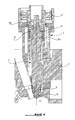
- FIG. 1 also represents a known injector whose body 1 is partially fixed in the cylinder head 2 of the engine via a base 3 integral with the cylinder head 2, being passed coaxially through the upper part of the injector body 1 and a nut 4 screwed into the upper part of the base 3 until it comes into abutment with the bottom of the housing of the base 3 so as to compress a spring 5 mounted coaxially around the injector body 1 between a shoulder 4a of the nut 4 and a flange 6a of a sleeve 6 secured coaxially to the upper part of the injector body 1.
- the compression of the spring 5 catches the axial play of the body injector relative to the cylinder head 2 so that the body 1 is maintained prestressed on a liner or casing 7 integral and the yoke 2 is traversed by the nose end 1a of the injector body 1 adjacent to the combustion chamber C of the corresponding cylinder of the engine and having a plurality of injection orifices opening into this chamber.
- the present invention aims to eliminate the above drawbacks by providing a fuel injector, in particular piezoelectric, a direct injection internal combustion engine, comprising an injector body housed coaxially in a sleeve secured to the cylinder head of the engine and whose nose end adjacent to the combustion chamber has a plurality of orifices opening into the combustion chamber, and which is characterized in that the injector body is mounted in the sleeve in axial clearance relative to the latter. and has at its upper part opposite its nose end a shoulder constantly abutting against a flange integral with the cylinder head by the action of the combustion pressure prevailing from the combustion chamber on the nose end of the injector body.
- the flange is fixed on a flat face of the yoke extending perpendicularly to the longitudinal axis of the injector body and comprises a machined surface on which bears the shoulder of the injector body, this surface being parallel to the flat face of the cylinder head and remote from the latter of a value equal to the axial play of the injector body.
- the flange is fixed directly in abutment on the flat face of the yoke and the machined surface of the flange constitutes the bottom of an internal recess in the form of the countersink of this flange.
- this axial clearance is between about 0.1 and 0.2 mm.
- the shoulder of the injector body is part of a collar of this body.
- the nose portion of the injector body is mounted in a sliding fit in the liner.
- a seal is interposed between the liner and the injector body.
- the invention also relates to an internal combustion engine with direct fuel injection, in particular four-cylinder, and which is characterized in that it is equipped with at least one injector as defined above.
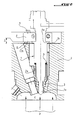
- the reference 1 designates the body of an injector, in particular piezoelectric control, implanted largely in the cylinder head 2 of a direct injection internal combustion engine, preferably four cylinders.
- the injector body 1 comprises therein an injector needle, not shown, slidably mounted longitudinally in the body 1 and whose end located on the side of the combustion chamber C of the associated cylinder of the engine comprises a surface of generally conical seal by which the needle cooperates with a valve seat formed in the nose end portion 1a of the injector body 1 to control the opening of at least one, not shown, injection port of fuel in the combustion chamber C.
- the injector body 1 is housed axially in a bore 2a of the yoke 2 and its lower part is housed coaxially in a jacket 3 secured to the yoke 2 in its bore 2a so that the nose end 1a of the body injector 1 opens into the combustion chamber C.
- the injector body 1 is mounted in the yoke 2 so as to be able to move freely in its axial or longitudinal direction relative to the yoke 2 in a very small clearance, preferably between about 0.1 mm and about 0.2mm, so as to take advantage of the combustion pressure P present in the combustion chamber C and acting on the free end of the nose of the injector body to move axially upwards relative to the figure 2 and position it in support of its upper part on a flange 4 secured to the yoke 2 by fixing screws 5.
- the nose portion 1a of the injector body 1 is mounted in a sliding fit in the corresponding lower part of the liner 3 and the injector body 1 has a flange 1b at its upper part opposite the nose 1a coming from support under the combustion pressure P on a machined flat surface 4a of the flange 4.
- the latter is fixed on a flat face 2b of the yoke 2 extending perpendicularly to the longitudinal axis of the injector body 1 so that the 4a surface of the flange 4 is arranged parallel above the face 2b to define the clearance J ensuring the plating of the flange 1b of the injector body 1 on the surface 4a of the flange 4.
- the flange 4 can be fixed on the face 2b of the yoke 2 by interposing spacing projections 6 between them.
- annular seal 7 is interposed between the jacket 3 and the injector body 1.
- the flange 4 is fixed, by the fastening screws 5, directly resting on the flat face 2b of the yoke 2 and the surface 4a of the flange 4 constitutes the bottom of a recess 4b in the form of countersink of this flange and spaced above the face 2b of the yoke 2 to define the clearance J ensuring the plating of the flange 1b of the injector body 1 on the surface 4a of the flange 4.
- This variant embodiment makes it possible to dispense with the spacing protrusions 6 of the injector of FIG. 2.
- the combustion pressure P constantly plates the injector body on the fixed flange 4.
- the implantation according to the invention of the injector in the cylinder head of an internal combustion engine makes it possible to use this injector, preferably with a piezoelectric control, in any four-cylinder gasoline direct injection internal combustion engine, without using a compression spring of the injector of the prior art increasing the bulk of it.
Landscapes
- Engineering & Computer Science (AREA)
- Chemical & Material Sciences (AREA)
- Combustion & Propulsion (AREA)
- Mechanical Engineering (AREA)
- General Engineering & Computer Science (AREA)
- Fuel-Injection Apparatus (AREA)
Abstract
Description
- La présente invention concerne un injecteur de carburant, notamment piézoélectrique, d'un moteur à combustion interne à injection directe.
- Elle vise également un moteur à combustion interne à injection directe à essence équipé d'au moins un tel injecteur.
- De nouvelles technologies d'injecteurs à commande piézoélectrique sont proposées pour les futurs moteurs à injection directe à essence.
- Cependant, ces injecteurs sont très fragiles et il est alors nécessaire de les fixer par bridage dans la culasse du moteur avec un dispositif de ressort pour plaquer de façon maîtrisée le corps de l'injecteur.
- Un tel dispositif à bride de fixation et ressort est décrit par exemple dans la demande de brevet
français N°2 746 856 - La figure 1 représente également un injecteur connu dont le corps 1 est partiellement fixé dans la culasse 2 du moteur par l'intermédiaire d'une embase 3 solidaire de la culasse 2 en étant traversée coaxialement par la partie supérieure du corps d'injecteur 1 et d'un écrou 4 vissé dans la partie supérieure de l'embase 3 jusqu'à venir en butée au fond du logement de l'embase 3 de manière à comprimer un ressort 5 monté coaxialement autour du corps d'injecteur 1 entre un épaulement 4a de l'écrou 4 et une collerette 6a d'un manchon 6 solidaire coaxialement de la partie supérieure du corps d'injecteur 1. La compression du ressort 5 rattrape le jeu axial du corps d'injecteur relativement à la culasse 2 de sorte que le corps 1 est maintenu précontraint sur une chemise ou boîtier 7 solidaire et la culasse 2 est traversée par l'extrémité formant nez 1a du corps d'injecteur 1 adjacente à la chambre de combustion C du cylindre correspondant du moteur et comportant plusieurs orifices d'injection débouchant dans cette chambre.
- Les solutions connues ci-dessus de positionnement d'un injecteur dans la culasse d'un moteur, qu'elles soient à bride et ressort ou à écrou et ressort ont pour inconvénient d'être d'une structure relativement complexe et surtout encombrante, ne s'adaptant pas à l'environnement du compartiment moteur du véhicule.
- En outre, ces solutions connues conviennent particulièrement à des moteurs à combustion interne à un seul cylindre ne posant pas de contrainte due à l'environnement du véhicule, mais sont difficilement adaptables à des moteurs à combustion interne à quatre cylindres ne laissant peu de place disponible dans le compartiment moteur du véhicule.
- La présente invention a pour but d'éliminer les inconvénients ci-dessus en proposant un injecteur de carburant, notamment piézoélectrique, d'un moteur à combustion interne à injection directe, comprenant un corps d'injecteur logé coaxialement dans une chemise solidaire de la culasse du moteur et dont l'extrémité formant nez adjacente à la chambre de combustion comporte plusieurs orifices débouchant dans la chambre de combustion, et qui est caractérisé en ce que le corps d'injecteur est monté dans la chemise suivant un jeu axial relativement à cette dernière et comporte à sa partie supérieure opposée à son extrémité formant nez un épaulement venant constamment en appui contre une bride solidaire de la culasse par l'action de la pression de combustion régnant de la chambre de combustion sur l'extrémité formant nez du corps d'injecteur.
- La bride est fixée sur une face plane de la culasse s'étendant perpendiculairement à l'axe longitudinal du corps d'injecteur et comporte une surface usinée sur laquelle vient en appui l'épaulement du corps d'injecteur, cette surface étant parallèle à la face plane de la culasse et distante de cette dernière d'une valeur égale au jeu axial du corps d'injecteur.
- Avantageusement, la bride est fixée directement en appui sur la face plane de la culasse et la surface usinée de la bride constitue le fond d'un évidement interne en forme de la lamage de cette bride.
- De préférence, ce jeu axial est compris entre environ 0,1 et 0,2 mm.
- L'épaulement du corps d'injecteur fait partie d'une collerette de ce corps.
- La partie formant nez du corps d'injecteur est montée suivant un ajustement glissant dans la chemise.
- Avantageusement, un joint d'étanchéité est interposé entre la chemise et le corps d'injecteur.
- L'invention vise également un moteur à combustion interne à injection directe à essence, notamment à quatre cylindres, et qui est caractérisé en ce qu'il est équipé d'au moins un injecteur tel que défini précédemment.
- L'invention sera mieux comprise, et d'autre buts, caractéristiques, détails et avantages de celle-ci apparaîtront plus clairement dans la description explicative qui va suivre faite en référence aux dessins donnés uniquement à titre d'exemple illustrant un mode de réalisation de l'invention et dans lesquels :
- La figure 1 est une vue en coupe longitudinale d'un injecteur implanté dans la culasse d'un moteur à combustion interne conformément à l'art antérieur ;
- La figure 2 est une vue en coupe longitudinale représentant un injecteur implanté dans la culasse d'un moteur à combustion interne conformément à l'invention ; et
- La figure 3 représente en coupe longitudinale une variante de réalisation de l'injecteur de la figure 2.
- En se reportant à la figure 2, la référence 1 désigne le corps d'un injecteur, notamment à commande piézoélectrique, implanté en grande partie dans la culasse 2 d'un moteur à combustion interne à injection directe, de préférence à quatre cylindres.
- Le corps d'injecteur 1 comporte dans celui-ci une aiguille d'injecteur, non représentée, montée coulissante longitudinalement dans le corps 1 et dont l'extrémité située du côté de la chambre de combustion C du cylindre associé du moteur comporte une surface d'étanchéité généralement conique par laquelle l'aiguille coopère avec un siège de soupape formé dans la partie d'extrémité formant nez la du corps d'injecteur 1 pour commander l'ouverture d'au moins un orifice, non représenté, d'injection de carburant dans la chambre de combustion C.
- Le corps d'injecteur 1 est logé axialement dans un perçage 2a de la culasse 2 et sa partie inférieure est logée coaxialement dans une chemise 3 solidaire de la culasse 2 dans son perçage 2a de manière que l'extrémité formant nez 1a du corps d'injecteur 1 débouche dans la chambre de combustion C.
- Selon l'invention, le corps d'injecteur 1 est monté dans la culasse 2 de manière à pouvoir se déplacer librement dans sa direction axiale ou longitudinale relativement à la culasse 2 suivant un très faible jeu, de préférence compris entre environ 0,1mm et environ 0,2mm, de manière à profiter de la pression de combustion P présente dans la chambre de combustion C et s'exerçant sur l'extrémité libre du nez la du corps d'injecteur pour le déplacer axialement vers le haut relativement à la figure 2 et le positionner en appui à sa partie supérieure sur une bride 4 solidaire de la culasse 2 par des vis de fixation 5.
- Plus précisément, la partie formant nez 1a du corps d'injecteur 1 est montée suivant un ajustement glissant dans la partie correspondante inférieure de la chemise 3 et le corps d'injecteur 1 comporte une collerette 1b à sa partie supérieure opposée au nez 1a venant en appui sous la pression de combustion P sur une surface plane usinée 4a de la bride 4. Cette dernière est fixée sur une face plane 2b de la culasse 2 s'étendant perpendiculairement à l'axe longitudinal du corps d'injecteur 1 de manière que la surface 4a de la bride 4 soit disposée parallèlement au-dessus de la face 2b pour définir le jeu J assurant le plaquage de la collerette 1b du corps d'injecteur 1 sur la surface 4a de la bride 4. Si nécessaire, la bride 4 peut être fixée sur la face 2b de la culasse 2 par interposition entre elles de saillies d'écartement 6.
- Avantageusement, un joint annulaire d'étanchéité 7 est interposé entre la chemise 3 et le corps d'injecteur 1.
- Selon la variante de réalisation représentée en figure 3, la bride 4 est fixée, par les vis de fixation 5, directement en appui sur la face plane 2b de la culasse 2 et la surface 4a de la bride 4 constitue le fond d'un évidement interne 4b en forme de lamage de cette bride et espacé au-dessus de la face 2b de la culasse 2 pour définir le jeu J assurant le plaquage de la collerette 1b du corps d'injecteur 1 sur la surface 4a de la bride 4. Cette variante de réalisation permet de se dispenser des saillies d'écartement 6 de l'injecteur de la figure 2.
- Ainsi, dès le démarrage du moteur, la pression de combustion P plaque constamment le corps d'injecteur sur la bride fixe 4.
- L'implantation conforme à l'invention de l'injecteur dans la culasse d'un moteur à combustion interne permet d'utiliser cet injecteur, de préférence à commande piézoélectrique, dans tout moteur à combustion interne à injection directe à essence à quatre cylindres, sans utiliser de ressort de compression de l'injecteur de l'art antérieur augmentant l'encombrement de celui-ci.
Claims (8)
- Injecteur de carburant, notamment piézoélectrique, d'un moteur à combustion interne à injection directe, comprenant un corps d'injecteur (1) logé coaxialement dans une chemise (3) solidaire de la culasse (2) du moteur et dont l'extrémité formant nez (1a) adjacente à la chambre de combustion (C) comporte plusieurs orifices débouchant dans la chambre de combustion, caractérisé en ce que le corps d'injecteur (1) est monté dans la chemise (3) suivant un jeu axial (J) relativement à cette dernière et comporte à sa partie supérieure opposée à son extrémité formant nez (1a) un épaulement (1b) venant constamment en appui contre une bride (4) solidaire de la culasse (2) par l'action de la pression de combustion (P) régnant dans la chambre de combustion (C) sur l'extrémité formant nez (1a) du corps d'injecteur (1).
- Injecteur selon la revendication 1, caractérisé en ce que la bride (4) est fixée sur une face plane (2b) de la culasse (2) s'étendant perpendiculairement à l'axe longitudinal du corps d'injecteur (1) et comporte une surface usinée (4a) sur laquelle vient en appui l'épaulement (1b) du corps d'injecteur (1), cette surface (4a) étant parallèle à la face plane (2b) de la culasse (2) et distante de cette dernière d'une valeur égale au jeu axial (J) du corps d'injecteur (1).
- Injecteur selon la revendication 2, caractérisé en ce que la bride (4) est fixée directement en appui sur la face plane (2b) de la culasse (2) et la surface usinée (4a) de la bride (4) constitue le fond d'un évidement interne (4b) en forme de lamage de cette bride.
- Injecteur selon l'une des revendications 1 à 3, caractérisé en ce que le jeu axial (J) est compris entre environ 0,1 et 0,2 mm.
- Injecteur selon l'une des revendications précédentes, caractérisé en ce que l'épaulement du corps d'injecteur (1) fait partie d'une collerette (1b) de ce corps.
- Injecteur selon l'une des revendications précédentes, caractérisé en ce que la partie formant nez (1a) du corps d'injecteur (1) est montée suivant un ajustement glissant dans la chemise (3).
- Injecteur selon l'une des revendications précédentes, caractérisé en ce qu'un joint d'étanchéité (7) est interposé entre la chemise (3) et le corps d'injecteur (1) .
- Moteur à combustion interne à injection directe à essence, notamment à quatre cylindres, caractérisé en ce qu'il est équipé d'au moins un injecteur tel que défini dans l'une quelconque des revendications 1 à 7.
Applications Claiming Priority (1)
| Application Number | Priority Date | Filing Date | Title |
|---|---|---|---|
| FR0511804A FR2893678B1 (fr) | 2005-11-22 | 2005-11-22 | Injecteur de carburant, notamment piezoelectrique, d'un moteur a combustion interne a injection directe |
Publications (1)
| Publication Number | Publication Date |
|---|---|
| EP1788234A1 true EP1788234A1 (fr) | 2007-05-23 |
Family
ID=36778318
Family Applications (1)
| Application Number | Title | Priority Date | Filing Date |
|---|---|---|---|
| EP06301156A Withdrawn EP1788234A1 (fr) | 2005-11-22 | 2006-11-20 | Injecteur de carburant, notamment piezoelectrique, d'un moteur a combustion interne a injection directe |
Country Status (2)
| Country | Link |
|---|---|
| EP (1) | EP1788234A1 (fr) |
| FR (1) | FR2893678B1 (fr) |
Citations (5)
| Publication number | Priority date | Publication date | Assignee | Title |
|---|---|---|---|---|
| FR2746856A1 (fr) | 1996-03-28 | 1997-10-03 | Stanadyne Automotive Corp | Injecteur de carburant |
| US5752487A (en) | 1997-06-11 | 1998-05-19 | Caterpillar Inc. | Injector combustion gas seal |
| DE19949627A1 (de) * | 1999-10-14 | 2001-04-26 | Siemens Ag | Einspritzventil mit verbesserter Bundgeometrie |
| WO2005026530A1 (fr) * | 2003-09-08 | 2005-03-24 | Siemens Aktiengesellschaft | Ensemble comprenant une soupape d'injection et un manchon en tant que moyen de transmission de pression |
| DE10340911A1 (de) * | 2003-09-05 | 2005-03-31 | Robert Bosch Gmbh | Spannhülse mit Temperaturkompensation |
-
2005
- 2005-11-22 FR FR0511804A patent/FR2893678B1/fr not_active Expired - Fee Related
-
2006
- 2006-11-20 EP EP06301156A patent/EP1788234A1/fr not_active Withdrawn
Patent Citations (5)
| Publication number | Priority date | Publication date | Assignee | Title |
|---|---|---|---|---|
| FR2746856A1 (fr) | 1996-03-28 | 1997-10-03 | Stanadyne Automotive Corp | Injecteur de carburant |
| US5752487A (en) | 1997-06-11 | 1998-05-19 | Caterpillar Inc. | Injector combustion gas seal |
| DE19949627A1 (de) * | 1999-10-14 | 2001-04-26 | Siemens Ag | Einspritzventil mit verbesserter Bundgeometrie |
| DE10340911A1 (de) * | 2003-09-05 | 2005-03-31 | Robert Bosch Gmbh | Spannhülse mit Temperaturkompensation |
| WO2005026530A1 (fr) * | 2003-09-08 | 2005-03-24 | Siemens Aktiengesellschaft | Ensemble comprenant une soupape d'injection et un manchon en tant que moyen de transmission de pression |
Also Published As
| Publication number | Publication date |
|---|---|
| FR2893678B1 (fr) | 2008-02-22 |
| FR2893678A1 (fr) | 2007-05-25 |
Similar Documents
| Publication | Publication Date | Title |
|---|---|---|
| FR2740177A1 (fr) | Injecteur a commande piezoelectrique pour systemes d'injection de carburant de moteurs a combustion interne | |
| EP0291386B1 (fr) | Injecteur pour moteur à allumage commandé et injection directe | |
| FR2808306A1 (fr) | Injecteur pour l'injection de carburant dans un systeme d'injection a rampe commune d'un moteur thermique | |
| FR2510195A1 (fr) | Dispositif d'alimentation en combustible pour moteur diesel | |
| WO2006108939A2 (fr) | Bougie de préchauffage à capteur de pression intégré et corps d'une telle bougie de préchauffage | |
| WO2010026315A1 (fr) | Dispositif intégrant un capteur de pression pour la mesure de pressions au sein d'un moteur à combustion interne ainsi qu'un corps d'un tel dispositif | |
| FR2474595A1 (fr) | Ensemble injecteur-pompe pour moteurs a combustion interne, reuni en une unite de construction | |
| WO2010066956A1 (fr) | Dispositif intégrant un capteur de pression pour la mesure de pressions au sein d'un moteur à combustion interne | |
| EP1913253B1 (fr) | Dispositif d'injection de carburant et procede de commande d'un tel dispositif | |
| FR2893678A1 (fr) | Injecteur de carburant, notamment piezoelectrique, d'un moteur a combustion interne a injection directe | |
| FR2756872A1 (fr) | Dispositif de fixation pour un injecteur de moteur a combustion interne | |
| EP0878622A1 (fr) | Une bride de fixation d'un injecteur | |
| FR2832189A1 (fr) | Dispositif de fixation d'un systeme d'injection de carburant pour moteur a combustion interne | |
| EP0774579B1 (fr) | Dispostif pour la fixation d'un injecteur de carburant sur une culasse de moteur à combustion interne | |
| FR2633663A1 (fr) | Systeme d'immobilisation en rotation d'une soupape | |
| FR2509381A1 (fr) | Pompe a injection de carburant | |
| FR2836701A1 (fr) | Dispositif de montage d'un tuyau d'injection de carburant | |
| EP1533519A1 (fr) | Moteur de vehicule comprenant un rail d'injecteur et un injecteur | |
| FR2836697A1 (fr) | Culasse de moteur a combustion interne, et moteur equipe d'une telle culasse | |
| JP2000249024A (ja) | エンジン用燃料噴射弁の取付け構造 | |
| EP1679437B1 (fr) | Dispositif d'amortissement de vibrations, ainsi que moteur à combustion interne comprenant un tel dispositif | |
| FR2933751A3 (fr) | Bride de fixation d'un injecteur sur un carter de moteur de vehicule automobile | |
| EP1297983B1 (fr) | Ligne d'échappement de véhicule automobile, comportant un batteur inertiel | |
| FR2890123A1 (fr) | Dispositif de fixation d'au moins un injecteur sur une culasse et moteur a combustion interne comprenant un tel dispositif | |
| FR2887303A1 (fr) | Dispositif de fixation d'un injecteur sur un carter chapeau palier |
Legal Events
| Date | Code | Title | Description |
|---|---|---|---|
| PUAI | Public reference made under article 153(3) epc to a published international application that has entered the european phase |
Free format text: ORIGINAL CODE: 0009012 |
|
| AK | Designated contracting states |
Kind code of ref document: A1 Designated state(s): AT BE BG CH CY CZ DE DK EE ES FI FR GB GR HU IE IS IT LI LT LU LV MC NL PL PT RO SE SI SK TR |
|
| AX | Request for extension of the european patent |
Extension state: AL BA HR MK YU |
|
| 17P | Request for examination filed |
Effective date: 20070919 |
|
| 17Q | First examination report despatched |
Effective date: 20071022 |
|
| AKX | Designation fees paid |
Designated state(s): AT BE BG CH CY CZ DE DK EE ES FI FR GB GR HU IE IS IT LI LT LU LV MC NL PL PT RO SE SI SK TR |
|
| GRAP | Despatch of communication of intention to grant a patent |
Free format text: ORIGINAL CODE: EPIDOSNIGR1 |
|
| STAA | Information on the status of an ep patent application or granted ep patent |
Free format text: STATUS: THE APPLICATION IS DEEMED TO BE WITHDRAWN |
|
| 18D | Application deemed to be withdrawn |
Effective date: 20100917 |