EP1787728B1 - Magnetic plate for printing of optical effects - Google Patents
Magnetic plate for printing of optical effects Download PDFInfo
- Publication number
- EP1787728B1 EP1787728B1 EP06255895.2A EP06255895A EP1787728B1 EP 1787728 B1 EP1787728 B1 EP 1787728B1 EP 06255895 A EP06255895 A EP 06255895A EP 1787728 B1 EP1787728 B1 EP 1787728B1
- Authority
- EP
- European Patent Office
- Prior art keywords
- region
- magnetic field
- sheet
- magnetic
- image
- Prior art date
- Legal status (The legal status is an assumption and is not a legal conclusion. Google has not performed a legal analysis and makes no representation as to the accuracy of the status listed.)
- Active
Links
- 230000003287 optical effect Effects 0.000 title description 3
- 239000000463 material Substances 0.000 claims description 26
- 238000000034 method Methods 0.000 claims description 26
- 239000000758 substrate Substances 0.000 claims description 24
- 239000002131 composite material Substances 0.000 claims description 21
- 239000003973 paint Substances 0.000 claims description 20
- 239000002184 metal Substances 0.000 claims description 11
- 239000006247 magnetic powder Substances 0.000 claims description 4
- 239000011230 binding agent Substances 0.000 claims description 2
- 239000000976 ink Substances 0.000 description 26
- 230000005415 magnetization Effects 0.000 description 15
- 239000002245 particle Substances 0.000 description 13
- 239000000696 magnetic material Substances 0.000 description 12
- 239000000049 pigment Substances 0.000 description 9
- 238000000576 coating method Methods 0.000 description 7
- 239000011248 coating agent Substances 0.000 description 6
- 230000000694 effects Effects 0.000 description 5
- 239000006249 magnetic particle Substances 0.000 description 5
- 238000010586 diagram Methods 0.000 description 4
- 239000007788 liquid Substances 0.000 description 4
- 238000004519 manufacturing process Methods 0.000 description 3
- 230000004907 flux Effects 0.000 description 2
- 230000001939 inductive effect Effects 0.000 description 2
- 230000001902 propagating effect Effects 0.000 description 2
- 238000004088 simulation Methods 0.000 description 2
- 239000007787 solid Substances 0.000 description 2
- 229910001209 Low-carbon steel Inorganic materials 0.000 description 1
- 230000015572 biosynthetic process Effects 0.000 description 1
- 239000008199 coating composition Substances 0.000 description 1
- 238000005094 computer simulation Methods 0.000 description 1
- 239000004020 conductor Substances 0.000 description 1
- 230000008034 disappearance Effects 0.000 description 1
- 229920002313 fluoropolymer Polymers 0.000 description 1
- 239000004811 fluoropolymer Substances 0.000 description 1
- 239000000203 mixture Substances 0.000 description 1
- 238000010422 painting Methods 0.000 description 1
- 229920000642 polymer Polymers 0.000 description 1
- 239000011347 resin Substances 0.000 description 1
- 229920005989 resin Polymers 0.000 description 1
- 239000012798 spherical particle Substances 0.000 description 1
Images


Classifications
-
- B—PERFORMING OPERATIONS; TRANSPORTING
- B05—SPRAYING OR ATOMISING IN GENERAL; APPLYING FLUENT MATERIALS TO SURFACES, IN GENERAL
- B05D—PROCESSES FOR APPLYING FLUENT MATERIALS TO SURFACES, IN GENERAL
- B05D3/00—Pretreatment of surfaces to which liquids or other fluent materials are to be applied; After-treatment of applied coatings, e.g. intermediate treating of an applied coating preparatory to subsequent applications of liquids or other fluent materials
- B05D3/20—Pretreatment of surfaces to which liquids or other fluent materials are to be applied; After-treatment of applied coatings, e.g. intermediate treating of an applied coating preparatory to subsequent applications of liquids or other fluent materials by magnetic fields
- B05D3/207—Pretreatment of surfaces to which liquids or other fluent materials are to be applied; After-treatment of applied coatings, e.g. intermediate treating of an applied coating preparatory to subsequent applications of liquids or other fluent materials by magnetic fields post-treatment by magnetic fields
-
- B—PERFORMING OPERATIONS; TRANSPORTING
- B05—SPRAYING OR ATOMISING IN GENERAL; APPLYING FLUENT MATERIALS TO SURFACES, IN GENERAL
- B05D—PROCESSES FOR APPLYING FLUENT MATERIALS TO SURFACES, IN GENERAL
- B05D3/00—Pretreatment of surfaces to which liquids or other fluent materials are to be applied; After-treatment of applied coatings, e.g. intermediate treating of an applied coating preparatory to subsequent applications of liquids or other fluent materials
- B05D3/06—Pretreatment of surfaces to which liquids or other fluent materials are to be applied; After-treatment of applied coatings, e.g. intermediate treating of an applied coating preparatory to subsequent applications of liquids or other fluent materials by exposure to radiation
-
- B—PERFORMING OPERATIONS; TRANSPORTING
- B05—SPRAYING OR ATOMISING IN GENERAL; APPLYING FLUENT MATERIALS TO SURFACES, IN GENERAL
- B05D—PROCESSES FOR APPLYING FLUENT MATERIALS TO SURFACES, IN GENERAL
- B05D3/00—Pretreatment of surfaces to which liquids or other fluent materials are to be applied; After-treatment of applied coatings, e.g. intermediate treating of an applied coating preparatory to subsequent applications of liquids or other fluent materials
- B05D3/14—Pretreatment of surfaces to which liquids or other fluent materials are to be applied; After-treatment of applied coatings, e.g. intermediate treating of an applied coating preparatory to subsequent applications of liquids or other fluent materials by electrical means
-
- B—PERFORMING OPERATIONS; TRANSPORTING
- B05—SPRAYING OR ATOMISING IN GENERAL; APPLYING FLUENT MATERIALS TO SURFACES, IN GENERAL
- B05D—PROCESSES FOR APPLYING FLUENT MATERIALS TO SURFACES, IN GENERAL
- B05D5/00—Processes for applying liquids or other fluent materials to surfaces to obtain special surface effects, finishes or structures
- B05D5/06—Processes for applying liquids or other fluent materials to surfaces to obtain special surface effects, finishes or structures to obtain multicolour or other optical effects
-
- B—PERFORMING OPERATIONS; TRANSPORTING
- B41—PRINTING; LINING MACHINES; TYPEWRITERS; STAMPS
- B41C—PROCESSES FOR THE MANUFACTURE OR REPRODUCTION OF PRINTING SURFACES
- B41C1/00—Forme preparation
-
- B—PERFORMING OPERATIONS; TRANSPORTING
- B41—PRINTING; LINING MACHINES; TYPEWRITERS; STAMPS
- B41N—PRINTING PLATES OR FOILS; MATERIALS FOR SURFACES USED IN PRINTING MACHINES FOR PRINTING, INKING, DAMPING, OR THE LIKE; PREPARING SUCH SURFACES FOR USE AND CONSERVING THEM
- B41N1/00—Printing plates or foils; Materials therefor
- B41N1/04—Printing plates or foils; Materials therefor metallic
-
- B—PERFORMING OPERATIONS; TRANSPORTING
- B41—PRINTING; LINING MACHINES; TYPEWRITERS; STAMPS
- B41C—PROCESSES FOR THE MANUFACTURE OR REPRODUCTION OF PRINTING SURFACES
- B41C1/00—Forme preparation
- B41C1/10—Forme preparation for lithographic printing; Master sheets for transferring a lithographic image to the forme
- B41C1/1058—Forme preparation for lithographic printing; Master sheets for transferring a lithographic image to the forme by providing a magnetic pattern, a ferroelectric pattern or a semiconductive pattern, e.g. by electrophotography
-
- G—PHYSICS
- G11—INFORMATION STORAGE
- G11B—INFORMATION STORAGE BASED ON RELATIVE MOVEMENT BETWEEN RECORD CARRIER AND TRANSDUCER
- G11B5/00—Recording by magnetisation or demagnetisation of a record carrier; Reproducing by magnetic means; Record carriers therefor
- G11B5/84—Processes or apparatus specially adapted for manufacturing record carriers
- G11B5/855—Coating only part of a support with a magnetic layer
-
- H—ELECTRICITY
- H01—ELECTRIC ELEMENTS
- H01F—MAGNETS; INDUCTANCES; TRANSFORMERS; SELECTION OF MATERIALS FOR THEIR MAGNETIC PROPERTIES
- H01F13/00—Apparatus or processes for magnetising or demagnetising
- H01F13/003—Methods and devices for magnetising permanent magnets
Definitions
- This invention relates generally to a magnet for use in printing inks and paints with magnetically alignable particles or flakes, and more particularly relates to forming magnets which have magnetic material aligned in a plurality of different directions in accordance with an applied field and to the use of these magnets as printing plates.
- sheet is used hereafter within this specification to mean a flat thin sheet, and in preferred embodiments as a flexible sheet; however the term sheet is not limited thereto.
- plate used throughout this specification is to mean a stiff or a flexible plate and is to include thin, flat flexible sheet, such as a composite magnetizable sheet or as a rubber magnetic sheet more commonly known when magnetized, as a "fridge" magnet.
- printing plate is used hereafter as a plate that will form an image, indicia or logo within an ink or paint of magnetically alignable flakes.
- the printing plate does not itself transfer ink or paint, but has the ability to move flakes or particles within a printing ink or paint so as to form a discernible print.
- United States Patents 6,808,806 , 6,759,097 , US 6,818,299 and US 6,838,166 disclose magnetically alignable flakes and utlizing magnets for aligning flakes in printed images. More particularly US 6,808,806 discloses the use of a flexible magnet having a cut out in a shape of a letter "F" and used for printing. In this embodiment the field emanating from the region surrounding the cut-out "F" was uniform and in a direction normal to the surface of the "F". Flakes that were over the cut-out portion having no field were substantially flat lying. Although this embodiment provides interesting images, this invention provides additional features, not achievable with a magnet having a uniform field.
- a method for producing a magnetically formed pattern on a product is the subject-matter of United States 5,630.877 .
- the product is produced by forming a paint layer from a paint medium mixed with magnetic non-spherical particles, and applying a magnetic field in a shape corresponding to the desired pattern to be formed.
- the field emanates from magnets mounted underneath the wet painted substrate. After the field aligns the particles, they are cured within the paint vehicle.
- United States patent 6,103,361 discloses patterned substrates useful in producing decorative cookware which are formed by coating of a substrate with a base consisting of a mixture of fluoropolymer and magnetic flakes and magnetically inducing an image in the polymer coating composition.
- the pattern is formed by applying magnetic force through the edges of a magnetizable die positioned under a coated base to induce an image effect.
- United States patent 6,759,097 discloses methods and devices for producing images on coated surfaces.
- the methods comprise applying a layer of magnetizable pigment coating in liquid form on a substrate, applying a magnetic field to selected regions of the pigment coating to alter the orientation of selected magnetic particles or flakes, and solidifying the reoriented particles or flakes in a non-parallel position to the surface of the pigment coating to produce an image such as a three dimensional-like image on the surface of the coating.
- the pigment coating can contain various interference or non-interference magnetic particles or flakes, such as magnetic color shifting pigments.
- EP 0 710 508 A1 discloses a process for producting layers that exhibits three dimensional optical effects through the alignment of magnetic pigments using a magnetic printing plate.
- the printing plate is formed by a writing process employing tapered pole pieces.
- EP1874487 A0 corresponding to WO 2006/114289 A1 and belonging to the state of the art according to 54(3) EPC, discloses a process for producing color effect images through the alignment of magnetic pigments using a magnetic printing plate.
- the printing plate is formed by a pixel based process employing a number of magnetic heads in a conintuous process.
- EP 1 493 590 A1 describes a device and a method for transferring a predetermined magnetic design onto document printed with magnetic optically variable ink.
- the device comprises a body of a composite permanent magnet material, having a surface engraved with the pattern corresponding to the pattern of desirable indicia.
- the magnetic material is magnetized in the direction perpendicular to the surface. Irregularities in the surface, made with an engraving, produce changes in the direction and strength of the resulting magnetic field. These changes cause different alignment of magnetic particles in different parts of the wet ink that make possible a formation of an image with a shape corresponding to the shape of engraving.
- the magnet does not require costly and difficult carving or removal of material so as to vary the field.
- logo or indicia is made within the magnetic material of a block or sheet so that the magnet will provide a field that corresponds the object, logo, or indicia when the field is used to align flakes in paint or ink.
- the image within the magnetic material is not visible to the eye, but is coded into the magnetic material so as to generate a field that corresponds to the object logo or indicia that is used to "code” the magnetic material.
- the object, logo or indicia encoded into the magnet cannot be seen, but is present and generates a magnetic field that aligns flakes placed on a substrate in the field to replicate the object, logo or indicia.
- a common "fridge" magnet can be encoded with magnetic information so as to change its field direction to form an image.
- this encoded magnet may be of flexible magnetic material and can be placed on a drum and used to "print" images within a wet inked or painted substrate by aligning particles in a manner that reflect the encoded magnetic information.
- prior art methods of applying a magnetic field to inks and or paints that have alignable flakes therein includes the use of recessed or embossed magnetic regions.
- this invention utilizes a magnet having a flat surface wherein magnetic and non-magnetic, or differently magnetized regions are provided within a single monolithic magnet that cause alignment of flakes forming images in a liquid in having field alignable flakes.
- Advantageously having a flat die or magnetic printing head or plate that is magnetized within eliminates problems associated with making and using 3-D magnetic forms.
- the flat die can be brought into intimate contact with the substrate and even if pressure is applied the result will be substantially the same. This is not the case with 3-D embossed or engraved magnetic printing plates.
- boundaries within the printed image can be made sharper with more ease then with embossed or recessed magnetic printing plates.
- a printing plate comprising: a body of magnetizable composite material, having a plurality of regions along a surface thereof; wherein a first region along the surface of the body of magnetizable composite material is magnetized such that the first region provides a first magnetic field having a predetermined direction and a second region along the surface of the body of magnetizable composite material, surrounding the first region, is either unmagnetized or magnetized differently from the first region, so as to provide a contrast in magnetic field there from characterized in that the first region is magnetized using a shaped magnetizing die having an outwardly facing surface in a form of an image, logo or indicia such that the first region has the form of the image, logo or indicia.
- a method of forming a printing plate comprising the steps of:
- the invention provides a printing plate wherein:
- FIG. 1a an engraved magnet is shown in Fig. 1a which is used to form a print within a substrate coated with wet ink or paint containing magnetically alignable particles or flakes.
- the magnet 10 is placed under the substrate and the flakes within the ink or paint align along the field lines forming the numeral 20.
- reflective flakes for example Ni, having a silver-like appearance in a blue carrier vehicle are aligned to form the numeral 20. The flakes appear to take on the color of the die and flakes within the background of the "20" and within the numerals themselves have a dark appearance.
- Embodiments of this invention are shown in Figs 3a through 3d . These are believed to be significant improvements over the magnets and samples shown in Figs 1a through 2d .
- a magnet 30b is shown wherein a magnetic charge confined to a region having the shape of the numeral 20 has been transferred from a die 32a into the magnet 30b forming a magnet within a region confined to the shape of the numeral 20, formed within the magnetic material itself.
- Two dies 32a and 32b made of mild steel were fabricated so that one die 32a, has a protruding number 20 and another has mirrored image of the numeral 20. Both dies were brought to contact with the non-magnetized sheet 30a disposed therebetween as shown in Fig. 3f .
- the sheet 30a is a non-magnetized flexible flat magnetic composite, capable of being magnetized if exposed to a strong magnetic field or charge.
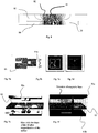
- a linear array of magnetic regions 109 are shown on the plate or sheet 104.
- Each magnetic region has an internal magnetic structure of a shape corresponding to the shape of the dies 105, 106 contacting the sheet 104.
- Magnetization of the regions can be conducted either by two-pole magnetizer as shown in Fig. 4 or one-pole magnetizer shown in Figures 5 and 6 .
- the north and south shoes 102 and 103 of magnetizer 101 may move in XY coordinates along the sheet of non-magnetized flexible material 104 as well as up and down.
- the sheet 104 may move between the shoes of the magnet. Relative movement is required in this embodiment between the flexible material 104 and the shoes 102, 103.
- the magnetic poles could function in a manner like a reciprocating hot stamp process where the sheet 104 is momentarily stopped and the dies 105 and 106 are lightly pressed against the sheet 104 and then removed after a approximately one second.
- the shaped dies 105 and 106 are fabricated from a soft magnetic material.
- the die 106 is mirrored to the die 105, in a same manner as dies 32a and 32b of Fig. 3 .
- the dies are attached to the shoes and can be brought to contact with the flexible magnet by adjustment of the distance between the shoes 102, 103.
- the shoes with the dies move along the plate to the place that needs to be magnetized and the shoes with the dies are brought to the dense contact with each other through the plate 104.
- the power of the magnetizer 101 is switched on to create a magnetic field between the dies.
- the generated field magnetizes the plate 104 in the region 107 with a magnetization direction perpendicular to the surface of the plate.
- the typical time of such a single magnetization process is close to 1 second.
- the shape of the magnetized area 107 has the shape of the die. After completion of magnetization of a particular region, the shoes spread apart and move to another position on the plate, leaving a non-magnetized space 108 between the magnetized areas 109.
- the die has a relief structure that contacts the plate, i.e. the numeral "20". Engraved regions of the die provide closer or further distance between the source of a magnetic field and the plate. This allows for the creation of a magnetization with gradient magnetic fields through the plate.
- two one-pole electromagnets as are shown in Fig. 5 can provide the same magnetization effect.
- series aiding electromagnets 201 and 202 are connected in the circuit to the power supplies 203 and 204 and to the computer 205 which provides positioning of the magnets along the plate 206 and their turning on and off.
- the shaped dies 206 and 207 are attached to the bottom of the magnet 201 and the top of the magnet 202.
- the magnets 201 and 202 are aligned on both sides of the plate 203 with their axis coincident.
- the magnets move in X-Y coordinates along the plate 205. In the place that needs to be magnetized, the magnets come toward each other so close that they are separated only by the thickness of the plate 205.
- the power turns on and the magnets generate magnetic field that in one second magnetizes selective area of the plate. After completion of the process, the magnets move to another position leaving magnetized areas 208
- a one-pole magnet can also magnetize the plate.
- a layout of such system is shown in Fig. 6 where an electromagnet 201 is connected with the power supply 203 and the computer 205.
- Substrate 205 has magnetized regions 208 repeating the shape of the die 207.
- FIG. 7 shows a simulation of a computer simulation of a magnetic field through such structure, placed inside of a magnetic charger (magnetizer), is shown in the picture "Magnetic field in the process of magnetization of non-magnetized magnetic composite". It is clear from the picture that the field flows into and through the dies that serve as magneto-conductors and flows mostly through the region of the flat magnetic material that is enclosed between the dies without substantial charging surrounding regions of the flat sheet. The magnitude of magnetic flux density along entire sheet shown in the lower part of the figure.
- Fig. 8 illustrates the field emanating from the sheet 30 made in Fig. 7 with the metal shoes or dies of Fig. 3f .
- a substrate with wet ink containing magnetic particles placed on a substrate on the top of the magnet 30 with the numeral "20" selectively magnetized in the sheet of magnetic rubber the background is bright and smooth and the 20 is dark and highly visible.
- the magnetized part of the sheet 81 is shown with mostly vertical field lines. Magnetic lines 82 emanating from the sheet within the air space 83 above the magnet 30. A non-magnetized part of the sheet 84 is shown absent of field lines.
- Figs 9a through 9f an alternate configuration and printing method is shown whereby a two-step process is applied.
- a sheet magnet 93 is shown having the numeral 20 magnetically encoded therein.
- a magnetized sheet 91a is shown which will be utilized after aligning flakes with the sheet magnet 93.
- the resulting images are shown in Figs. 9c and 9d .
- the two steps of the process are shown more clearly in Figs. 9e and 9f .
- the dies 90a and 90b with the embossed numerals 20 are used to magnetize the sheet with the encoding of the numeral 20. Subsequently the same magnetic sheet is magnetized by two magnets 91a and 91b.
- the resulting magnetized sheet magnet was used to align flakes in both of the samples shown in Figs 9c and 9d .
- the magnetic charge source is not shown connected to 90a, 90b or 91a or 91b although this is required.
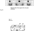
- Fig. 10 illustrates the magnetic field within the magnetized sheet 93 wherein the magnet within the sheet has a two-pole orientation.
- Fig. 12 is an alternative embodiment of the invention wherein a "fridge magnet" or pre-magnetized magnet is re-magnetized is a desired region.
- Fig. 12 is a representation of where the magnet is within the block or sheet shown.
- Fig. 13 is a drawing of an image printed with the magnet shown in Fig. 10 .
- the lines of magnetization shown within the "fridge" magnet are duplicated in the image of Fig. 13 as the flakes in the image are algined along the field lines.
- the numeral 20 magnetized into the fridge magnet can be done with very strong permanent magnets or by inducing a magnetic charge through one or more dies.
- "fridge" magnets are generally magnetized having spaced rows of magnets are within the same monolithic magnetic block or sheet. As was shown these magnets can be re-magnetized such that they become encoded mangetically with indicia such as numerals or letters or logos, or images.
- FIG. 11 illustrates the complex task of producing a numeral "1" form a solid magnetic block.
- a die must be cut from the solid block. If the die is incorrectly cut, or if the magnet is not handled carefully it can break or crack.
- the magnet formed within the flexible magnet is quite robust and easy to manufacture.
- the magnetic shape is created with a magnetic field, and the magnet is flexible.
- a magnetic sheet or block is used for align magnetically alignable flakes.
- flakes of various kinds may be used; for example reflective flakes, multilayer flakes, color shifting flakes, diffractive flakes, flakes having covert features therein, highly absorbing flakes and any other form of flakes that can be aligned in a magnetic field.
Landscapes
- Engineering & Computer Science (AREA)
- Manufacturing & Machinery (AREA)
- Physics & Mathematics (AREA)
- Plasma & Fusion (AREA)
- Printing Methods (AREA)
- Manufacture Or Reproduction Of Printing Formes (AREA)
Applications Claiming Priority (1)
| Application Number | Priority Date | Filing Date | Title |
|---|---|---|---|
| US73792605P | 2005-11-18 | 2005-11-18 |
Publications (2)
| Publication Number | Publication Date |
|---|---|
| EP1787728A1 EP1787728A1 (en) | 2007-05-23 |
| EP1787728B1 true EP1787728B1 (en) | 2020-02-19 |
Family
ID=37846046
Family Applications (1)
| Application Number | Title | Priority Date | Filing Date |
|---|---|---|---|
| EP06255895.2A Active EP1787728B1 (en) | 2005-11-18 | 2006-11-17 | Magnetic plate for printing of optical effects |
Country Status (11)
| Country | Link |
|---|---|
| US (1) | US7717038B2 (ja) |
| EP (1) | EP1787728B1 (ja) |
| JP (1) | JP5259946B2 (ja) |
| KR (1) | KR101469273B1 (ja) |
| CN (1) | CN1966278B (ja) |
| AU (1) | AU2006236078B2 (ja) |
| CA (1) | CA2568274C (ja) |
| ES (1) | ES2782327T3 (ja) |
| RU (1) | RU2431570C2 (ja) |
| SG (1) | SG132628A1 (ja) |
| TW (1) | TWI378867B (ja) |
Families Citing this family (36)
| Publication number | Priority date | Publication date | Assignee | Title |
|---|---|---|---|---|
| US7047883B2 (en) | 2002-07-15 | 2006-05-23 | Jds Uniphase Corporation | Method and apparatus for orienting magnetic flakes |
| US11230127B2 (en) | 2002-07-15 | 2022-01-25 | Viavi Solutions Inc. | Method and apparatus for orienting magnetic flakes |
| DE102005019919A1 (de) * | 2005-04-27 | 2006-11-16 | Leonhard Kurz Gmbh & Co. Kg | Verfahren zur Erzeugung von Farbeffektbildern |
| AU2007200128B8 (en) | 2006-01-17 | 2013-02-07 | Viavi Solutions Inc. | Apparatus for orienting magnetic flakes |
| MX2009004094A (es) * | 2006-10-17 | 2009-05-01 | Sicpa Holding Sa | Metodo y medios para producir indicios magneticamente inducidos en una cubierta que contiene particulas magneticas. |
| EP1990208A1 (en) * | 2007-05-10 | 2008-11-12 | Kba-Giori S.A. | Device and method for magnetically transferring indica to a coating composition applied to a substrate |
| KR101000681B1 (ko) | 2008-11-11 | 2010-12-10 | 현대자동차주식회사 | 3차원 패턴 형성을 위한 자기 도장 장치 및 방법 |
| US20140111296A1 (en) * | 2012-10-24 | 2014-04-24 | Correlated Magnetics Research, Llc | System and method for producing magnetic structures |
| US20140211360A1 (en) * | 2009-06-02 | 2014-07-31 | Correlated Magnetics Research, Llc | System and method for producing magnetic structures |
| DE102010041398A1 (de) | 2009-10-22 | 2011-04-28 | Manroland Ag | Einrichtung und Verfahren zum Beschichten |
| JP2011126074A (ja) * | 2009-12-16 | 2011-06-30 | Process Bunkado:Kk | 磁気印刷用版及びその版を用いた印刷方法 |
| CA2717256C (en) | 2010-05-14 | 2018-05-01 | Sterling Marking Products Inc. | Removable print element assembly for a hand printer |
| CN102442097A (zh) * | 2010-09-30 | 2012-05-09 | 王玉珠 | 一种磁力印刷方法及其印刷产品 |
| JP2012130899A (ja) * | 2010-12-21 | 2012-07-12 | Ryong Kim | 磁力を利用した器具コーティング方法及びコーティング装置 |
| US20120156398A1 (en) * | 2010-12-21 | 2012-06-21 | Kim Ryong | Method and apparatus for coating utensils using magnetic force |
| US8523236B2 (en) | 2011-02-07 | 2013-09-03 | Jenny Leary | Magnetic field surface image method, kit and product |
| CN102490448B (zh) * | 2011-10-20 | 2014-01-15 | 惠州市华阳光学技术有限公司 | 磁性印刷母版及其制造方法以及制造设备 |
| IN2014MN01369A (ja) | 2012-01-12 | 2015-05-29 | Jds Uniphase Corp | |
| CN102642419B (zh) * | 2012-04-11 | 2014-10-08 | 惠州市华阳光学技术有限公司 | 印刷磁定向母版的制造方法 |
| CN103552370B (zh) * | 2013-11-05 | 2015-10-21 | 德信嘉邦涂料(深圳)有限公司 | 一种磁定向组件及磁性油墨印刷设备 |
| CN103950280B (zh) * | 2014-05-15 | 2016-01-20 | 常德金鹏印务有限公司 | 一种可实现磁定向组合的印刷设备 |
| CN103950279B (zh) * | 2014-05-15 | 2016-02-10 | 常德金鹏印务有限公司 | 一种带可变图形磁定向装置的印刷设备 |
| CN104290480A (zh) * | 2014-10-13 | 2015-01-21 | 广东乐佳印刷有限公司 | 一种磁性印刷控制赋磁图案的方法 |
| FR3031027B1 (fr) * | 2014-12-30 | 2017-06-09 | Seb Sa | Procede de decoration d'un article culinaire par traitement mecanique |
| WO2016112529A1 (en) * | 2015-01-16 | 2016-07-21 | Microsoft Technology Licensing, Llc | Formation of substrates having ink including magnetic material |
| HUE055299T2 (hu) * | 2016-07-29 | 2021-11-29 | Sicpa Holding Sa | Eljárások effekt rétegek elõállítására |
| EP3500374B1 (en) * | 2016-08-16 | 2021-04-07 | Sicpa Holding Sa | Processes for producing effects layers |
| JP6213886B1 (ja) | 2016-08-22 | 2017-10-18 | Zero Lab株式会社 | 磁気消去具 |
| CA3025430C (en) * | 2016-09-22 | 2024-02-20 | Sicpa Holding Sa | Apparatuses and processes for producing optical effect layers comprising oriented non-spherical magnetic or magnetizable pigment particles |
| CN106531197A (zh) * | 2016-11-01 | 2017-03-22 | 广东浪潮大数据研究有限公司 | 一种定位设备、硬盘驱动器及充磁方法 |
| US10212300B2 (en) * | 2016-12-09 | 2019-02-19 | Lexmark International, Inc. | Magnetic keys having a plurality of magnetic plates |
| US10357991B2 (en) | 2016-12-19 | 2019-07-23 | Viavi Solutions Inc. | Security ink based security feature |
| DE102017112015A1 (de) * | 2017-05-31 | 2018-12-06 | Heinatz GmbH | Vorrichtungen und Verfahren zum magnetischen Drucken und Druckerzeugnis |
| JP6946121B2 (ja) | 2017-09-07 | 2021-10-06 | 東芝テック株式会社 | 磁気インク読取装置及びプリンタ |
| DE102018003096A1 (de) * | 2018-04-17 | 2019-10-17 | Burkhard Büstgens | Drop-on-Demand - Beschichtung von Oberflächen |
| CN111942060A (zh) * | 2020-08-25 | 2020-11-17 | 彭亮 | 一种浮雕光变防伪元件 |
Family Cites Families (30)
| Publication number | Priority date | Publication date | Assignee | Title |
|---|---|---|---|---|
| US3120806A (en) * | 1957-04-24 | 1964-02-11 | Ibm | Magnetic image plate |
| US3683382A (en) * | 1969-05-29 | 1972-08-08 | Honeywell Inc | Recording medium responsive to force fields and apparatus for recording and reproducing signals on the medium |
| US3845499A (en) * | 1969-09-25 | 1974-10-29 | Honeywell Inc | Apparatus for orienting magnetic particles having a fixed and varying magnetic field component |
| US3853676A (en) | 1970-07-30 | 1974-12-10 | Du Pont | Reference points on films containing curved configurations of magnetically oriented pigment |
| DE2752895A1 (de) * | 1976-12-06 | 1978-06-08 | Emi Ltd | Verfahren zur herstellung einer materialschicht, deren oberflaeche ein abtastbares muster aufweist, sowie sicherheitsdokumentensystem |
| US5766738A (en) * | 1979-12-28 | 1998-06-16 | Flex Products, Inc. | Paired optically variable article with paired optically variable structures and ink, paint and foil incorporating the same and method |
| JPH0248949A (ja) * | 1988-08-11 | 1990-02-19 | Mitsubishi Heavy Ind Ltd | オフセット印刷方法 |
| US5317340A (en) * | 1990-08-23 | 1994-05-31 | Mody Hemant K | Method and device for erasing and writing on magnetic recording media suitable for direct viewing |
| US5129321A (en) * | 1991-07-08 | 1992-07-14 | Rockwell International Corporation | Direct-to-press imaging system for use in lithographic printing |
| JPH05337436A (ja) * | 1992-06-11 | 1993-12-21 | Hashimoto Forming Ind Co Ltd | 所定形状の模様を有する成形品及びこの成形品の製造方法 |
| DE69218582T2 (de) | 1992-02-21 | 1997-07-10 | Hashimoto Forming Kogyo Co | Lackierung mit magnetisch hergestelltem Muster und lackiertes Produkt mit magnetisch hergestelltem Muster |
| DE4439455A1 (de) | 1994-11-04 | 1996-05-09 | Basf Ag | Verfahren zur Herstellung von dreidimensionale optische Effekte aufweisenden Beschichtungen |
| EP0756272A3 (en) * | 1995-07-28 | 1997-05-07 | Eastman Kodak Co | Magnetic medium with permanent magnetic characteristics |
| US5949050A (en) * | 1997-01-22 | 1999-09-07 | Mattel, Inc. | Magnetic cards having a layer being permanently magnetized in a fixed configuration |
| US6103361A (en) * | 1997-09-08 | 2000-08-15 | E. I. Du Pont De Nemours And Company | Patterned release finish |
| US7047883B2 (en) * | 2002-07-15 | 2006-05-23 | Jds Uniphase Corporation | Method and apparatus for orienting magnetic flakes |
| US7517578B2 (en) * | 2002-07-15 | 2009-04-14 | Jds Uniphase Corporation | Method and apparatus for orienting magnetic flakes |
| US7604855B2 (en) * | 2002-07-15 | 2009-10-20 | Jds Uniphase Corporation | Kinematic images formed by orienting alignable flakes |
| US20020160194A1 (en) | 2001-04-27 | 2002-10-31 | Flex Products, Inc. | Multi-layered magnetic pigments and foils |
| US6808806B2 (en) | 2001-05-07 | 2004-10-26 | Flex Products, Inc. | Methods for producing imaged coated articles by using magnetic pigments |
| US6902807B1 (en) | 2002-09-13 | 2005-06-07 | Flex Products, Inc. | Alignable diffractive pigment flakes |
| US6692830B2 (en) * | 2001-07-31 | 2004-02-17 | Flex Products, Inc. | Diffractive pigment flakes and compositions |
| US6841238B2 (en) * | 2002-04-05 | 2005-01-11 | Flex Products, Inc. | Chromatic diffractive pigments and foils |
| US7258900B2 (en) * | 2002-07-15 | 2007-08-21 | Jds Uniphase Corporation | Magnetic planarization of pigment flakes |
| US7674501B2 (en) * | 2002-09-13 | 2010-03-09 | Jds Uniphase Corporation | Two-step method of coating an article for security printing by application of electric or magnetic field |
| US7645510B2 (en) | 2002-09-13 | 2010-01-12 | Jds Uniphase Corporation | Provision of frames or borders around opaque flakes for covert security applications |
| US7241489B2 (en) | 2002-09-13 | 2007-07-10 | Jds Uniphase Corporation | Opaque flake for covert security applications |
| EP1493590A1 (en) | 2003-07-03 | 2005-01-05 | Sicpa Holding S.A. | Method and means for producing a magnetically induced design in a coating containing magnetic particles |
| CA2541568C (en) * | 2005-04-06 | 2014-05-13 | Jds Uniphase Corporation | Dynamic appearance-changing optical devices (dacod) printed in a shaped magnetic field including printable fresnel structures |
| DE102005019919A1 (de) | 2005-04-27 | 2006-11-16 | Leonhard Kurz Gmbh & Co. Kg | Verfahren zur Erzeugung von Farbeffektbildern |
-
2006
- 2006-11-16 SG SG200607955-2A patent/SG132628A1/en unknown
- 2006-11-16 JP JP2006310355A patent/JP5259946B2/ja active Active
- 2006-11-16 KR KR1020060113338A patent/KR101469273B1/ko active IP Right Grant
- 2006-11-16 AU AU2006236078A patent/AU2006236078B2/en active Active
- 2006-11-16 CA CA2568274A patent/CA2568274C/en active Active
- 2006-11-17 EP EP06255895.2A patent/EP1787728B1/en active Active
- 2006-11-17 RU RU2006140728/12A patent/RU2431570C2/ru active
- 2006-11-17 ES ES06255895T patent/ES2782327T3/es active Active
- 2006-11-17 US US11/560,927 patent/US7717038B2/en active Active
- 2006-11-17 TW TW095142643A patent/TWI378867B/zh active
- 2006-11-20 CN CN2006101497479A patent/CN1966278B/zh active Active
Non-Patent Citations (1)
| Title |
|---|
| None * |
Also Published As
| Publication number | Publication date |
|---|---|
| US7717038B2 (en) | 2010-05-18 |
| KR101469273B1 (ko) | 2014-12-04 |
| TW200734182A (en) | 2007-09-16 |
| CA2568274C (en) | 2014-08-12 |
| KR20070053126A (ko) | 2007-05-23 |
| EP1787728A1 (en) | 2007-05-23 |
| US20070115337A1 (en) | 2007-05-24 |
| CN1966278A (zh) | 2007-05-23 |
| RU2006140728A (ru) | 2008-05-27 |
| AU2006236078A1 (en) | 2007-06-07 |
| CN1966278B (zh) | 2011-11-30 |
| ES2782327T3 (es) | 2020-09-14 |
| RU2431570C2 (ru) | 2011-10-20 |
| SG132628A1 (en) | 2007-06-28 |
| CA2568274A1 (en) | 2007-05-18 |
| JP2007176155A (ja) | 2007-07-12 |
| AU2006236078B2 (en) | 2011-10-13 |
| TWI378867B (en) | 2012-12-11 |
| JP5259946B2 (ja) | 2013-08-07 |
Similar Documents
| Publication | Publication Date | Title |
|---|---|---|
| EP1787728B1 (en) | Magnetic plate for printing of optical effects | |
| JP5155467B2 (ja) | 磁性粒子を含有するコーティング中に磁気的に誘導した模様をもたらすための方法および手段 | |
| EP3663007B1 (en) | Apparatus for orienting magnetic flakes | |
| US7588817B2 (en) | Engraved optically variable image device | |
| SA07280527B1 (ar) | طريقة ووسائل لنقل علامات مميزة مغناطيسياً إلى تركيبة مغلِّفة موضوعة على طبقة تحتية | |
| CA2574140C (en) | Apparatus for orienting magnetic flakes |
Legal Events
| Date | Code | Title | Description |
|---|---|---|---|
| PUAI | Public reference made under article 153(3) epc to a published international application that has entered the european phase |
Free format text: ORIGINAL CODE: 0009012 |
|
| AK | Designated contracting states |
Kind code of ref document: A1 Designated state(s): AT BE BG CH CY CZ DE DK EE ES FI FR GB GR HU IE IS IT LI LT LU LV MC NL PL PT RO SE SI SK TR |
|
| AX | Request for extension of the european patent |
Extension state: AL BA HR MK YU |
|
| 17P | Request for examination filed |
Effective date: 20071123 |
|
| AKX | Designation fees paid |
Designated state(s): AT BE BG CH CY CZ DE DK EE ES FI FR GB GR HU IE IS IT LI LT LU LV MC NL PL PT RO SE SI SK TR |
|
| 17Q | First examination report despatched |
Effective date: 20080213 |
|
| RAP1 | Party data changed (applicant data changed or rights of an application transferred) |
Owner name: VIAVI SOLUTIONS INC. |
|
| RAP1 | Party data changed (applicant data changed or rights of an application transferred) |
Owner name: VIAVI SOLUTIONS INC. |
|
| REG | Reference to a national code |
Ref country code: DE Ref legal event code: R079 Ref document number: 602006059138 Country of ref document: DE Free format text: PREVIOUS MAIN CLASS: B05D0003140000 Ipc: B05D0003000000 |
|
| GRAP | Despatch of communication of intention to grant a patent |
Free format text: ORIGINAL CODE: EPIDOSNIGR1 |
|
| STAA | Information on the status of an ep patent application or granted ep patent |
Free format text: STATUS: GRANT OF PATENT IS INTENDED |
|
| RIC1 | Information provided on ipc code assigned before grant |
Ipc: B41N 1/04 20060101ALI20190815BHEP Ipc: B05D 3/00 20060101AFI20190815BHEP Ipc: G11B 5/855 20060101ALN20190815BHEP Ipc: B41C 1/10 20060101ALN20190815BHEP Ipc: B05D 5/06 20060101ALI20190815BHEP Ipc: B41C 1/00 20060101ALI20190815BHEP Ipc: H01F 13/00 20060101ALN20190815BHEP |
|
| INTG | Intention to grant announced |
Effective date: 20190916 |
|
| GRAS | Grant fee paid |
Free format text: ORIGINAL CODE: EPIDOSNIGR3 |
|
| GRAA | (expected) grant |
Free format text: ORIGINAL CODE: 0009210 |
|
| STAA | Information on the status of an ep patent application or granted ep patent |
Free format text: STATUS: THE PATENT HAS BEEN GRANTED |
|
| REG | Reference to a national code |
Ref country code: DE Ref legal event code: R081 Ref document number: 602006059138 Country of ref document: DE Owner name: VIAVI SOLUTIONS INC., SAN JOSE, US Free format text: FORMER OWNER: JDS UNIPHASE CORP., MILPITAS, CALIF., US |
|
| AK | Designated contracting states |
Kind code of ref document: B1 Designated state(s): AT BE BG CH CY CZ DE DK EE ES FI FR GB GR HU IE IS IT LI LT LU LV MC NL PL PT RO SE SI SK TR |
|
| REG | Reference to a national code |
Ref country code: GB Ref legal event code: FG4D |
|
| REG | Reference to a national code |
Ref country code: CH Ref legal event code: EP |
|
| REG | Reference to a national code |
Ref country code: DE Ref legal event code: R096 Ref document number: 602006059138 Country of ref document: DE |
|
| REG | Reference to a national code |
Ref country code: AT Ref legal event code: REF Ref document number: 1234338 Country of ref document: AT Kind code of ref document: T Effective date: 20200315 |
|
| REG | Reference to a national code |
Ref country code: IE Ref legal event code: FG4D |
|
| REG | Reference to a national code |
Ref country code: SE Ref legal event code: TRGR |
|
| REG | Reference to a national code |
Ref country code: CH Ref legal event code: NV Representative=s name: MURGITROYD AND COMPANY, CH |
|
| REG | Reference to a national code |
Ref country code: NL Ref legal event code: MP Effective date: 20200219 |
|
| PG25 | Lapsed in a contracting state [announced via postgrant information from national office to epo] |
Ref country code: FI Free format text: LAPSE BECAUSE OF FAILURE TO SUBMIT A TRANSLATION OF THE DESCRIPTION OR TO PAY THE FEE WITHIN THE PRESCRIBED TIME-LIMIT Effective date: 20200219 |
|
| REG | Reference to a national code |
Ref country code: LT Ref legal event code: MG4D |
|
| PG25 | Lapsed in a contracting state [announced via postgrant information from national office to epo] |
Ref country code: LV Free format text: LAPSE BECAUSE OF FAILURE TO SUBMIT A TRANSLATION OF THE DESCRIPTION OR TO PAY THE FEE WITHIN THE PRESCRIBED TIME-LIMIT Effective date: 20200219 Ref country code: BG Free format text: LAPSE BECAUSE OF FAILURE TO SUBMIT A TRANSLATION OF THE DESCRIPTION OR TO PAY THE FEE WITHIN THE PRESCRIBED TIME-LIMIT Effective date: 20200519 Ref country code: IS Free format text: LAPSE BECAUSE OF FAILURE TO SUBMIT A TRANSLATION OF THE DESCRIPTION OR TO PAY THE FEE WITHIN THE PRESCRIBED TIME-LIMIT Effective date: 20200619 Ref country code: GR Free format text: LAPSE BECAUSE OF FAILURE TO SUBMIT A TRANSLATION OF THE DESCRIPTION OR TO PAY THE FEE WITHIN THE PRESCRIBED TIME-LIMIT Effective date: 20200520 |
|
| REG | Reference to a national code |
Ref country code: ES Ref legal event code: FG2A Ref document number: 2782327 Country of ref document: ES Kind code of ref document: T3 Effective date: 20200914 |
|
| PG25 | Lapsed in a contracting state [announced via postgrant information from national office to epo] |
Ref country code: NL Free format text: LAPSE BECAUSE OF FAILURE TO SUBMIT A TRANSLATION OF THE DESCRIPTION OR TO PAY THE FEE WITHIN THE PRESCRIBED TIME-LIMIT Effective date: 20200219 |
|
| PG25 | Lapsed in a contracting state [announced via postgrant information from national office to epo] |
Ref country code: SK Free format text: LAPSE BECAUSE OF FAILURE TO SUBMIT A TRANSLATION OF THE DESCRIPTION OR TO PAY THE FEE WITHIN THE PRESCRIBED TIME-LIMIT Effective date: 20200219 Ref country code: PT Free format text: LAPSE BECAUSE OF FAILURE TO SUBMIT A TRANSLATION OF THE DESCRIPTION OR TO PAY THE FEE WITHIN THE PRESCRIBED TIME-LIMIT Effective date: 20200712 Ref country code: RO Free format text: LAPSE BECAUSE OF FAILURE TO SUBMIT A TRANSLATION OF THE DESCRIPTION OR TO PAY THE FEE WITHIN THE PRESCRIBED TIME-LIMIT Effective date: 20200219 Ref country code: CZ Free format text: LAPSE BECAUSE OF FAILURE TO SUBMIT A TRANSLATION OF THE DESCRIPTION OR TO PAY THE FEE WITHIN THE PRESCRIBED TIME-LIMIT Effective date: 20200219 Ref country code: LT Free format text: LAPSE BECAUSE OF FAILURE TO SUBMIT A TRANSLATION OF THE DESCRIPTION OR TO PAY THE FEE WITHIN THE PRESCRIBED TIME-LIMIT Effective date: 20200219 Ref country code: EE Free format text: LAPSE BECAUSE OF FAILURE TO SUBMIT A TRANSLATION OF THE DESCRIPTION OR TO PAY THE FEE WITHIN THE PRESCRIBED TIME-LIMIT Effective date: 20200219 Ref country code: DK Free format text: LAPSE BECAUSE OF FAILURE TO SUBMIT A TRANSLATION OF THE DESCRIPTION OR TO PAY THE FEE WITHIN THE PRESCRIBED TIME-LIMIT Effective date: 20200219 |
|
| REG | Reference to a national code |
Ref country code: AT Ref legal event code: MK05 Ref document number: 1234338 Country of ref document: AT Kind code of ref document: T Effective date: 20200219 |
|
| REG | Reference to a national code |
Ref country code: DE Ref legal event code: R097 Ref document number: 602006059138 Country of ref document: DE |
|
| PLBE | No opposition filed within time limit |
Free format text: ORIGINAL CODE: 0009261 |
|
| STAA | Information on the status of an ep patent application or granted ep patent |
Free format text: STATUS: NO OPPOSITION FILED WITHIN TIME LIMIT |
|
| 26N | No opposition filed |
Effective date: 20201120 |
|
| PG25 | Lapsed in a contracting state [announced via postgrant information from national office to epo] |
Ref country code: AT Free format text: LAPSE BECAUSE OF FAILURE TO SUBMIT A TRANSLATION OF THE DESCRIPTION OR TO PAY THE FEE WITHIN THE PRESCRIBED TIME-LIMIT Effective date: 20200219 Ref country code: IT Free format text: LAPSE BECAUSE OF FAILURE TO SUBMIT A TRANSLATION OF THE DESCRIPTION OR TO PAY THE FEE WITHIN THE PRESCRIBED TIME-LIMIT Effective date: 20200219 |
|
| PG25 | Lapsed in a contracting state [announced via postgrant information from national office to epo] |
Ref country code: PL Free format text: LAPSE BECAUSE OF FAILURE TO SUBMIT A TRANSLATION OF THE DESCRIPTION OR TO PAY THE FEE WITHIN THE PRESCRIBED TIME-LIMIT Effective date: 20200219 Ref country code: SI Free format text: LAPSE BECAUSE OF FAILURE TO SUBMIT A TRANSLATION OF THE DESCRIPTION OR TO PAY THE FEE WITHIN THE PRESCRIBED TIME-LIMIT Effective date: 20200219 |
|
| PG25 | Lapsed in a contracting state [announced via postgrant information from national office to epo] |
Ref country code: MC Free format text: LAPSE BECAUSE OF FAILURE TO SUBMIT A TRANSLATION OF THE DESCRIPTION OR TO PAY THE FEE WITHIN THE PRESCRIBED TIME-LIMIT Effective date: 20200219 |
|
| PG25 | Lapsed in a contracting state [announced via postgrant information from national office to epo] |
Ref country code: LU Free format text: LAPSE BECAUSE OF NON-PAYMENT OF DUE FEES Effective date: 20201117 |
|
| PG25 | Lapsed in a contracting state [announced via postgrant information from national office to epo] |
Ref country code: TR Free format text: LAPSE BECAUSE OF FAILURE TO SUBMIT A TRANSLATION OF THE DESCRIPTION OR TO PAY THE FEE WITHIN THE PRESCRIBED TIME-LIMIT Effective date: 20200219 Ref country code: CY Free format text: LAPSE BECAUSE OF FAILURE TO SUBMIT A TRANSLATION OF THE DESCRIPTION OR TO PAY THE FEE WITHIN THE PRESCRIBED TIME-LIMIT Effective date: 20200219 |
|
| PGFP | Annual fee paid to national office [announced via postgrant information from national office to epo] |
Ref country code: BE Payment date: 20221129 Year of fee payment: 17 |
|
| P01 | Opt-out of the competence of the unified patent court (upc) registered |
Effective date: 20230530 |
|
| PGFP | Annual fee paid to national office [announced via postgrant information from national office to epo] |
Ref country code: GB Payment date: 20231127 Year of fee payment: 18 |
|
| PGFP | Annual fee paid to national office [announced via postgrant information from national office to epo] |
Ref country code: ES Payment date: 20231206 Year of fee payment: 18 |
|
| PGFP | Annual fee paid to national office [announced via postgrant information from national office to epo] |
Ref country code: SE Payment date: 20231124 Year of fee payment: 18 Ref country code: IE Payment date: 20231128 Year of fee payment: 18 Ref country code: FR Payment date: 20231123 Year of fee payment: 18 Ref country code: DE Payment date: 20231124 Year of fee payment: 18 Ref country code: CH Payment date: 20231201 Year of fee payment: 18 |
|
| PGFP | Annual fee paid to national office [announced via postgrant information from national office to epo] |
Ref country code: BE Payment date: 20231122 Year of fee payment: 18 |