EP1786085A2 - Permanent magnet rotating electric machine - Google Patents
Permanent magnet rotating electric machine Download PDFInfo
- Publication number
- EP1786085A2 EP1786085A2 EP06255766A EP06255766A EP1786085A2 EP 1786085 A2 EP1786085 A2 EP 1786085A2 EP 06255766 A EP06255766 A EP 06255766A EP 06255766 A EP06255766 A EP 06255766A EP 1786085 A2 EP1786085 A2 EP 1786085A2
- Authority
- EP
- European Patent Office
- Prior art keywords
- rotor
- magnet
- permanent magnet
- rotating electric
- electric machine
- Prior art date
- Legal status (The legal status is an assumption and is not a legal conclusion. Google has not performed a legal analysis and makes no representation as to the accuracy of the status listed.)
- Granted
Links
- 238000003780 insertion Methods 0.000 claims abstract description 17
- 230000037431 insertion Effects 0.000 claims abstract description 17
- 238000004804 winding Methods 0.000 claims abstract description 9
- XEEYBQQBJWHFJM-UHFFFAOYSA-N Iron Chemical group [Fe] XEEYBQQBJWHFJM-UHFFFAOYSA-N 0.000 claims abstract description 5
- 230000003247 decreasing effect Effects 0.000 abstract description 7
- 238000004519 manufacturing process Methods 0.000 abstract description 4
- 238000000034 method Methods 0.000 description 12
- 239000000126 substance Substances 0.000 description 7
- 239000012212 insulator Substances 0.000 description 6
- 229910000976 Electrical steel Inorganic materials 0.000 description 4
- 230000000052 comparative effect Effects 0.000 description 4
- 238000005259 measurement Methods 0.000 description 3
- 239000003960 organic solvent Substances 0.000 description 3
- 229920006332 epoxy adhesive Polymers 0.000 description 2
- 230000004907 flux Effects 0.000 description 2
- 230000005415 magnetization Effects 0.000 description 2
- 239000000463 material Substances 0.000 description 2
- 229910001172 neodymium magnet Inorganic materials 0.000 description 2
- XAGFODPZIPBFFR-UHFFFAOYSA-N aluminium Chemical compound [Al] XAGFODPZIPBFFR-UHFFFAOYSA-N 0.000 description 1
- 229910052782 aluminium Inorganic materials 0.000 description 1
- 238000000137 annealing Methods 0.000 description 1
- 229910052799 carbon Inorganic materials 0.000 description 1
- 230000008859 change Effects 0.000 description 1
- 230000008878 coupling Effects 0.000 description 1
- 238000010168 coupling process Methods 0.000 description 1
- 238000005859 coupling reaction Methods 0.000 description 1
- 229910003460 diamond Inorganic materials 0.000 description 1
- 239000010432 diamond Substances 0.000 description 1
- 238000005516 engineering process Methods 0.000 description 1
- 239000003822 epoxy resin Substances 0.000 description 1
- 230000008020 evaporation Effects 0.000 description 1
- 238000001704 evaporation Methods 0.000 description 1
- 239000011810 insulating material Substances 0.000 description 1
- 238000000465 moulding Methods 0.000 description 1
- 230000002093 peripheral effect Effects 0.000 description 1
- 229920000647 polyepoxide Polymers 0.000 description 1
- 229910052761 rare earth metal Inorganic materials 0.000 description 1
- 150000002910 rare earth metals Chemical class 0.000 description 1
- 230000009467 reduction Effects 0.000 description 1
- 238000005245 sintering Methods 0.000 description 1
- 229910001220 stainless steel Inorganic materials 0.000 description 1
- 239000010935 stainless steel Substances 0.000 description 1
Images


Classifications
-
- H—ELECTRICITY
- H02—GENERATION; CONVERSION OR DISTRIBUTION OF ELECTRIC POWER
- H02K—DYNAMO-ELECTRIC MACHINES
- H02K1/00—Details of the magnetic circuit
- H02K1/06—Details of the magnetic circuit characterised by the shape, form or construction
- H02K1/22—Rotating parts of the magnetic circuit
- H02K1/27—Rotor cores with permanent magnets
- H02K1/2706—Inner rotors
- H02K1/272—Inner rotors the magnetisation axis of the magnets being perpendicular to the rotor axis
- H02K1/274—Inner rotors the magnetisation axis of the magnets being perpendicular to the rotor axis the rotor consisting of two or more circumferentially positioned magnets
- H02K1/2753—Inner rotors the magnetisation axis of the magnets being perpendicular to the rotor axis the rotor consisting of two or more circumferentially positioned magnets the rotor consisting of magnets or groups of magnets arranged with alternating polarity
- H02K1/276—Magnets embedded in the magnetic core, e.g. interior permanent magnets [IPM]
Definitions
- the present invention relates to permanent magnet rotating electric machines.
- Magnets with enhanced properties have high electrical conductivity, and it has been a problem in that in high-speed or large-sized rotating electric machines, a decrease in efficiency is caused by an eddy current generated in magnets.
- Japanese patent application Unexamined publication No.H11-4555A/1999 describes a rotating electric machine in which an eddy current in a permanent magnet is decreased by interposing insulating materials between electrically conductive permanent magnet materials having enhanced properties.
- the present invention provides a permanent magnet rotating electric machine in which heat damage to a magnet is prevented, eddy current loss is reduced while decreasing an eddy current generated in a permanent magnet, and furthermore, time and cost for manufacturing the rotating electric machine can be reduced.
- a plurality of permanent magnets may be disposed inside or on the surface of a rotor iron core, and the permanent magnets may be annularly arranged side by side at a distance from one another along the circumferential direction of the rotor such that the adjacent permanent magnet may have different magnetic pole direction.
- Each permanent magnet may comprise an electrically conductive magnet and may comprise an assembly of magnet pieces which may be arranged side by side in the circumferential direction, the axial direction, or both of the circumferential and axial directions of the rotor so that an eddy current generated in the permanent magnet is decreased. Accordingly, an insulating member is not placed between the magnet pieces.
- the present invention provides a permanent magnet rotating electric machine comprising a stator having a plurality of salient stator poles wound with windings; and a rotor separated from the stator by a rotation air gap and rotatably held, wherein the rotor may comprise a rotor iron core having therein a plurality of permanent magnet insertion holes annularly arranged side by side at a distance from one another along a circumferential direction of the rotor; and permanent magnets inserted into the plurality of the permanent magnet insertion holes such that the permanent magnets in the insertion holes adjacent to each other along the circumferential direction of the rotor have different magnetic pole directions from each other, and wherein the permanent magnets each may comprise a plurality of magnet pieces arranged side by side and may have a structure in which nothing may be interposed between the magnet pieces.
- an insulator containing an organic solvent is used as an insulator such as an epoxy resin.
- an organic solvent evaporates at high temperatures, so that such a permanent magnet cannot be used.
- evaporation of an organic solvent may not occur at high temperatures and even in a vacuum, so that the permanent magnet can be used without causing a problem.
- FIG. 1 shows a cross-sectional view of a permanent magnet rotating electric machine
- FIG. 2 shows a plan view of the permanent magnet rotating electric machine.
- the permanent magnet rotating electric machine comprises a stator 1 and a rotor 2
- the stator 1 comprises a stator iron core 3 and stator windings 4.
- the rotor 2 has a shaft held by bearings 5 and can rotate freely.
- a plurality of holes 6 for insertion of permanent magnets may be formed in the rotor 2, and the permanent magnets 7 may be inserted into the holes 6 and fixed therein.
- Each of the permanent magnets 7 shown in FIGS. 1 and 2 may be preferably divided in the circumferential direction and/or the axial direction, and more preferably divided in the axial direction especially in order to distribute stress.
- Each of the permanent magnet 7 may be divided only in the circumferential direction.
- the number of divisions may depend on the length of the rotating machine, but it is desirable that a single magnet may be usually divided into 3 to 15 parts in one direction. It should be noted that as shown in FIG. 3, the permanent magnets may be formed such that magnet pieces within a single row may be magnetized in the same direction and arranged parallel to one another.
- the magnet pieces which have been obtained by dividing the identical sintered permanent magnet by cutting may be preferable in terms of their good uniformity of magnetization.
- the sintered permanent magnet may be obtained by molding into a shape which may fit in the size of the permanent magnet insertion holes 6 and by sintering.
- the sintered permanent magnet may be annealed prior to the division by cutting in order to render the direction of magnetization uniform.
- the annealing temperature is preferably 150 to 1000°C, more preferably 300 to 900°C.
- the method for dividing the sintered permanent magnet may include cutting the sintered permanent magnet with such as a diamond cutter, a wire saw, or a cutting machine with a peripheral cutting edge. These divided magnets can be each individually inserted into the holes 6, or the divided magnets can be integrated by a fixing member and then inserted into the holes 6.
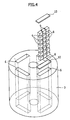
- the method for fixing a plurality of magnet pieces without interposing a substance between them may be a method of using the top and bottom rotor lids 10 when disposing the magnet pieces 8 in the permanent magnet insertion holes 6, as shown in the perspective view of FIG. 4. This method may enable fixation between the magnet pieces 9 especially in the axial direction.
- the magnet pieces 8 are also possible to arrange the magnet pieces 8 on a magnet fixing plate 11 without interposing a substance between the magnet pieces. Furthermore, as shown in FIG. 6, it is also possible to fix the magnet pieces in both of the circumferential direction and the axial direction with a magnet fixing band 12 around the magnet pieces to bind them together.
- the material of the magnet piece fixing member such as the plate-like fixing case 11 and the fixing band 12 described above, either of magnetic substances and non-magnetic substances can be used, as long as the magnetic field to be generated is not affected, and examples thereof may include aluminum and stainless steel.
- the magnets may be divided individually, so that eddy current loss can be reduced, and furthermore, it is not necessary to comprise a step of interposing a substance between the magnet pieces, so that the number of steps can be reduced significantly.
- the operating temperature of the permanent magnet rotating electric machine according to the present invention is preferably 50 to 350°C, and even when the permanent magnet rotating electric machine is operated at a high temperature of 200°C or more, stress generated inside a magnet can be considerably reduced.
- the upper limit of the operating temperature can be 350°C, as long as the above-described range is not exceeded.
- the permanent magnet rotating electric machine according to the present invention can be used as an electric motor preferably having a rotating speed of 2000 rpm to several tens of thousands rpm and a power of 10 kW to 1 MW.
- a rotating electric machine as shown in FIG. 2 having maximum rotating speed of 7200 rpm was used.
- a stator was made of a silicon-steel plate.
- the stator comprised salient stator poles wound with windings.
- the stator outer diameter was 300 mm and a stator inner diameter was 150 mm.
- a rotor was made of a silicon-steel plate. The rotor had permanent magnet having dimensions of 60 mm ⁇ 16 mm ⁇ 150 mm in each four insertion holes.
- Nd-Fe-B magnet which was an electrically conductive rare-earth sintered magnet
- the magnet had BHmax of 48 MGOe.
- this magnet was divided into three parts in the direction of the dimension of 60 mm and divided into seven parts in the direction of the dimension of 150 mm to make magnet pieces.
- the obtained magnet pieces were individually inserted into holes without interposing a substance between the magnet pieces and then fixed using lids made of SUS304.
- This rotating electric machine was driven by applying currents having frequencies ranging from 85 Hz to 240 Hz corresponding to rotational speeds of 2550 rpm to 7200 rpm to three-phase windings composed of the stator of this rotating electric machine.
- the condition of the rotor with regard to damage during this procedure was studied by increasing temperature to 180°C, 200°C and 240°C.
- the rotor using the permanent magnets comprising magnet pieces was not changed at any of temperatures 180°C, 200°C and 240°C.
- a rotor was made in the same manner as in Example 1, except that 100 ⁇ m of an epoxy adhesive were applied between magnet pieces and the magnet pieces were stuck together.
- a rotating electric machine provided with this rotor was assembled, and the rotating electric machine was driven by applying currents having frequencies corresponding to rotational speeds to three-phase windings provided in the rotating electric machine to increase the temperature, and the condition of the rotor with regard to damage during this procedure was studied.
- the rotor was not changed at 180°C, a color change was observed at 200°C, and the coupling between the magnet pieces was lost and the magnet pieces were separated at 240°C.
- a rotating electric machine whose cross section was as shown in FIG. 2 was used.
- Each permanent magnet having dimensions of 52 mm ⁇ 7.5 mm ⁇ 150 mm was inserted into each of four insertion holes of a rotor having an outer diameter of 200 mm, wherein the rotor was made of a silicon-steel plate.
- the rated output power of this rotating electric machine was 50 kW at the rated amperage of 200 A.
- a stator having an outer diameter of 300 mm had salient stator poles wound with windings.
- the stator was made of a silicon-steel plate.
- a Nd-Fe-B sintered magnet having BHmax of 48 MGOe was used as a permanent magnets and divided into three parts in the direction of the dimension of 52 mm and divided into seven parts in the direction of the dimension of 150 mm to make magnet pieces. Divided magnet pieces were then assembled again without interposing a substance between the magnet pieces. Both ends of the magnet were covered with lids of SUS304 and the lids were fixed with bolts to the rotor.
- This rotating electric machine was driven at the temperature of 20°C, 180°C, 200°C and 240°C respectively by applying rated sinusoidal currents to three-phase windings disposed in the stator.
- the rotating speed was fixed at the rated speed of 2550 rpm.
- the divided magnet pieces were then taken out of the insertion holes, bound with a band, and subjected to measurement of torsional fracture strength by a load cell.
- the torsional fracture strength refers to the force required for fracturing the magnet in the middle keeping both ends of the magnet fixed.
- Example 2 The divided magnet pieces were assembled in the same manner as in Example 2, except that 80 ⁇ m of an epoxy adhesive were applied between magnet pieces and the magnet pieces were stuck together.
- the rotating electric machine was then driven in the same manner as in Example 2.
- the measurement of the torsional fracture strength was then performed in the same manner as in Example 2. The result is shown in Table 1.
- Table 1 shows that the decrease of the torsional fracture strength of Example 2 due to the increase of the operating temperature was suppressed, while the torsional fracture strength of Comparative Example 2 was drastically decreased.
Landscapes
- Engineering & Computer Science (AREA)
- Power Engineering (AREA)
- Permanent Field Magnets Of Synchronous Machinery (AREA)
Abstract
Description
- The present invention relates to permanent magnet rotating electric machines.
- It is known that the efficiency of rotating electric machines can be increased by using permanent magnets to generate a field magnetic flux. Recently, the magnetic flux density in an air gap has been increased by using magnets with enhanced properties, so that it is possible to configure an efficient and compact rotating electric machine. Moreover, with enhancement of the properties of magnets and advancement of technologies, the range of the use of permanent magnet rotating electric machines has been increased, and permanent magnets with enhanced properties have become used even in rotating electric machines for high-speed rotation and large-sized rotating electric machines.
- Magnets with enhanced properties have high electrical conductivity, and it has been a problem in that in high-speed or large-sized rotating electric machines, a decrease in efficiency is caused by an eddy current generated in magnets. In order to solve this problem,
Japanese patent application Unexamined publication No.H11-4555A/1999 - However, with the technique described in the above prior art, the difference in the coefficient of thermal expansion between an insulator and an electrically conductive permanent magnet causes stress, which sometimes results in, for example, breakage of the magnet. Moreover, since insulating members are interposed between magnet pieces, it takes time and cost for uniformly disposing the insulating members and for manufacturing the rotating electric machine. Furthermore, due to the disposition of insulating members between magnet pieces, the above-mentioned technique brings problems such as a reduction in the properties of magnets.
- The present invention provides a permanent magnet rotating electric machine in which heat damage to a magnet is prevented, eddy current loss is reduced while decreasing an eddy current generated in a permanent magnet, and furthermore, time and cost for manufacturing the rotating electric machine can be reduced.
- In the permanent magnet rotating electric machine according to the present invention, a plurality of permanent magnets may be disposed inside or on the surface of a rotor iron core, and the permanent magnets may be annularly arranged side by side at a distance from one another along the circumferential direction of the rotor such that the adjacent permanent magnet may have different magnetic pole direction. Each permanent magnet may comprise an electrically conductive magnet and may comprise an assembly of magnet pieces which may be arranged side by side in the circumferential direction, the axial direction, or both of the circumferential and axial directions of the rotor so that an eddy current generated in the permanent magnet is decreased. Accordingly, an insulating member is not placed between the magnet pieces.
- More specifically, the present invention provides a permanent magnet rotating electric machine comprising a stator having a plurality of salient stator poles wound with windings; and a rotor separated from the stator by a rotation air gap and rotatably held, wherein the rotor may comprise a rotor iron core having therein a plurality of permanent magnet insertion holes annularly arranged side by side at a distance from one another along a circumferential direction of the rotor; and permanent magnets inserted into the plurality of the permanent magnet insertion holes such that the permanent magnets in the insertion holes adjacent to each other along the circumferential direction of the rotor have different magnetic pole directions from each other, and wherein the permanent magnets each may comprise a plurality of magnet pieces arranged side by side and may have a structure in which nothing may be interposed between the magnet pieces.
- In a permanent magnet having an insulator between magnet pieces, an insulator containing an organic solvent is used as an insulator such as an epoxy resin. However, there may be a problem in that, in a vacuum, the organic solvent evaporates at high temperatures, so that such a permanent magnet cannot be used. In the permanent magnet comprising magnet pieces in the permanent magnet rotating electric machine according to the present invention, evaporation of an organic solvent may not occur at high temperatures and even in a vacuum, so that the permanent magnet can be used without causing a problem.
- Moreover, when a permanent magnet is divided as a measure to cope with eddy current and when an insulator or the like is present between the magnet pieces, damage to the permanent magnet may be caused at high temperatures by the difference in the coefficient of expansion and also by a heat resistance problem of the insulator. According to the present invention, nothing is interposed between the divided magnet pieces, and thus it may be possible to relax stress in the magnet, which may be caused by temperature rise, and to provide a heat-resistant magnet in which an eddy current is decreased, and furthermore to reduce cost and processing time significantly.
-
- FIG. 1 shows a cross-sectional view of a permanent magnet rotating electric machine.
- FIG. 2 shows a plan view of a permanent magnet rotating electric machine.
- FIG. 3 shows a plan view of magnet pieces in one permanent magnet insertion hole taken along the magnetic pole direction.
- FIG. 4 shows a perspective view of a rotor and an example of a method for inserting magnet pieces into a magnet insertion hole and a method for fixing the magnet pieces.
- FIG. 5 shows an example of the method for fixing magnet pieces.
- FIG. 6 shows another example of the method for fixing magnet pieces.
- FIG. 1 shows a cross-sectional view of a permanent magnet rotating electric machine, and FIG. 2 shows a plan view of the permanent magnet rotating electric machine.
- This embodiment is described using a permanent magnet rotating electric machine in which a stator coil has six poles and a rotor has four permanent magnet poles, however, the present invention also can be applied to those having other numbers of salient poles.
- In Figs. 1 and 2, the permanent magnet rotating electric machine comprises a
stator 1 and arotor 2, and thestator 1 comprises astator iron core 3 andstator windings 4. - The
rotor 2 has a shaft held bybearings 5 and can rotate freely. - Moreover, a plurality of
holes 6 for insertion of permanent magnets may be formed in therotor 2, and thepermanent magnets 7 may be inserted into theholes 6 and fixed therein. - Each of the
permanent magnets 7 shown in FIGS. 1 and 2 may be preferably divided in the circumferential direction and/or the axial direction, and more preferably divided in the axial direction especially in order to distribute stress. Each of thepermanent magnet 7 may be divided only in the circumferential direction. - The number of divisions may depend on the length of the rotating machine, but it is desirable that a single magnet may be usually divided into 3 to 15 parts in one direction. It should be noted that as shown in FIG. 3, the permanent magnets may be formed such that magnet pieces within a single row may be magnetized in the same direction and arranged parallel to one another.
- The magnet pieces which have been obtained by dividing the identical sintered permanent magnet by cutting may be preferable in terms of their good uniformity of magnetization. The sintered permanent magnet may be obtained by molding into a shape which may fit in the size of the permanent
magnet insertion holes 6 and by sintering. The sintered permanent magnet may be annealed prior to the division by cutting in order to render the direction of magnetization uniform. The annealing temperature is preferably 150 to 1000°C, more preferably 300 to 900°C. - The method for dividing the sintered permanent magnet may include cutting the sintered permanent magnet with such as a diamond cutter, a wire saw, or a cutting machine with a peripheral cutting edge. These divided magnets can be each individually inserted into the
holes 6, or the divided magnets can be integrated by a fixing member and then inserted into theholes 6. - The method for fixing a plurality of magnet pieces without interposing a substance between them may be a method of using the top and
bottom rotor lids 10 when disposing themagnet pieces 8 in the permanentmagnet insertion holes 6, as shown in the perspective view of FIG. 4. This method may enable fixation between themagnet pieces 9 especially in the axial direction. - Moreover, as shown in FIG. 5, it is also possible to arrange the
magnet pieces 8 on amagnet fixing plate 11 without interposing a substance between the magnet pieces. Furthermore, as shown in FIG. 6, it is also possible to fix the magnet pieces in both of the circumferential direction and the axial direction with amagnet fixing band 12 around the magnet pieces to bind them together. Regarding the material of the magnet piece fixing member such as the plate-like fixing case 11 and thefixing band 12 described above, either of magnetic substances and non-magnetic substances can be used, as long as the magnetic field to be generated is not affected, and examples thereof may include aluminum and stainless steel. - As described above, by employing, for example, a configuration as shown in FIGS. 4 to 6, nothing is interposed between the magnet pieces, so that stress due to the difference of expansion coefficient between magnet pieces and the insulating member at high temperatures does not occur, and thus, damage to the magnets can be prevented. Moreover, the magnets may be divided individually, so that eddy current loss can be reduced, and furthermore, it is not necessary to comprise a step of interposing a substance between the magnet pieces, so that the number of steps can be reduced significantly.
- Accordingly, even when an electrically conductive permanent magnet is used, it is possible to provide a permanent magnet with which occurrence of stress is suppressed, and furthermore, an eddy current can be decreased and the manufacturing process can be shortened, and it is possible to provide a rotating electric machine in which stress in a magnet caused by temperature fluctuations is considerably reduced.
- The operating temperature of the permanent magnet rotating electric machine according to the present invention is preferably 50 to 350°C, and even when the permanent magnet rotating electric machine is operated at a high temperature of 200°C or more, stress generated inside a magnet can be considerably reduced. The upper limit of the operating temperature can be 350°C, as long as the above-described range is not exceeded.
- Hereinafter, the present invention will be described based on a working example, however, the present invention is not limited to this working example.
- The permanent magnet rotating electric machine according to the present invention can be used as an electric motor preferably having a rotating speed of 2000 rpm to several tens of thousands rpm and a power of 10 kW to 1 MW.
- A rotating electric machine as shown in FIG. 2 having maximum rotating speed of 7200 rpm was used. A stator was made of a silicon-steel plate. The stator comprised salient stator poles wound with windings. The stator outer diameter was 300 mm and a stator inner diameter was 150 mm. A rotor was made of a silicon-steel plate. The rotor had permanent magnet having dimensions of 60 mm × 16 mm × 150 mm in each four insertion holes.
- For the permanent magnets, a Nd-Fe-B magnet, which was an electrically conductive rare-earth sintered magnet, was used. The magnet had BHmax of 48 MGOe. As shown in FIG. 3, this magnet was divided into three parts in the direction of the dimension of 60 mm and divided into seven parts in the direction of the dimension of 150 mm to make magnet pieces. At this time, the obtained magnet pieces were individually inserted into holes without interposing a substance between the magnet pieces and then fixed using lids made of SUS304.
- This rotating electric machine was driven by applying currents having frequencies ranging from 85 Hz to 240 Hz corresponding to rotational speeds of 2550 rpm to 7200 rpm to three-phase windings composed of the stator of this rotating electric machine. The condition of the rotor with regard to damage during this procedure was studied by increasing temperature to 180°C, 200°C and 240°C.
- The rotor using the permanent magnets comprising magnet pieces was not changed at any of temperatures 180°C, 200°C and 240°C.
- A rotor was made in the same manner as in Example 1, except that 100 µm of an epoxy adhesive were applied between magnet pieces and the magnet pieces were stuck together. A rotating electric machine provided with this rotor was assembled, and the rotating electric machine was driven by applying currents having frequencies corresponding to rotational speeds to three-phase windings provided in the rotating electric machine to increase the temperature, and the condition of the rotor with regard to damage during this procedure was studied. The rotor was not changed at 180°C, a color change was observed at 200°C, and the coupling between the magnet pieces was lost and the magnet pieces were separated at 240°C.
- A rotating electric machine whose cross section was as shown in FIG. 2 was used. Each permanent magnet having dimensions of 52 mm × 7.5 mm × 150 mm was inserted into each of four insertion holes of a rotor having an outer diameter of 200 mm, wherein the rotor was made of a silicon-steel plate. The rated output power of this rotating electric machine was 50 kW at the rated amperage of 200 A. A stator having an outer diameter of 300 mm had salient stator poles wound with windings. The stator was made of a silicon-steel plate.
- A Nd-Fe-B sintered magnet having BHmax of 48 MGOe was used as a permanent magnets and divided into three parts in the direction of the dimension of 52 mm and divided into seven parts in the direction of the dimension of 150 mm to make magnet pieces. Divided magnet pieces were then assembled again without interposing a substance between the magnet pieces. Both ends of the magnet were covered with lids of SUS304 and the lids were fixed with bolts to the rotor.
- This rotating electric machine was driven at the temperature of 20°C, 180°C, 200°C and 240°C respectively by applying rated sinusoidal currents to three-phase windings disposed in the stator. The rotating speed was fixed at the rated speed of 2550 rpm.
- The divided magnet pieces were then taken out of the insertion holes, bound with a band, and subjected to measurement of torsional fracture strength by a load cell. The torsional fracture strength refers to the force required for fracturing the magnet in the middle keeping both ends of the magnet fixed.
- The measurement was performed for four samples at each temperature and the average of the four samples was calculated. The result is shown in Table 1.
- The divided magnet pieces were assembled in the same manner as in Example 2, except that 80 µm of an epoxy adhesive were applied between magnet pieces and the magnet pieces were stuck together. The rotating electric machine was then driven in the same manner as in Example 2. The measurement of the torsional fracture strength was then performed in the same manner as in Example 2. The result is shown in Table 1.
Table1 Temperature Example 2 (relative value) Comparative Example 2 (relative value) 20° C 1 1 180°C 1.01 0.9 200°C 0.92 0.42 240°C 0.89 0.03 - Table 1 shows that the decrease of the torsional fracture strength of Example 2 due to the increase of the operating temperature was suppressed, while the torsional fracture strength of Comparative Example 2 was drastically decreased.
Claims (4)
- A permanent magnet rotating electric machine, comprising:a stator having a plurality of salient stator poles wound with windings; anda rotor separated from the stator by a rotation air gap and held rotatably,wherein the rotor comprises:a rotor iron core having therein a plurality of permanent magnet insertion holes annularly arranged side by side at a distance from one another along a circumferential direction of the rotor; andpermanent magnets inserted into the plurality of permanent magnet insertion holes such that the permanent magnets in the insertion holes adjacent to each other along the circumferential direction of the rotor have different magnetic pole directions from each other, andwherein the permanent magnets each comprises a plurality of magnet pieces arranged side by side and has a structure in which nothing is interposed between the magnet pieces.
- The permanent magnet rotating electric machine according to claim 1, wherein the permanent magnets each comprises a plurality of magnet pieces arranged side by side along the circumferential direction and/or an axial direction of the rotor.
- The permanent magnet rotating electric machine according to claim 1, wherein the permanent magnets each comprises a plurality of magnet pieces arranged side by side along an axial direction of the rotor.
- The permanent magnet rotating electric machine according to any one of claims 1 to 3, wherein the magnet pieces are obtained by dividing the identical sintered permanent magnet.
Applications Claiming Priority (1)
| Application Number | Priority Date | Filing Date | Title |
|---|---|---|---|
| JP2005330348 | 2005-11-15 |
Publications (3)
| Publication Number | Publication Date |
|---|---|
| EP1786085A2 true EP1786085A2 (en) | 2007-05-16 |
| EP1786085A3 EP1786085A3 (en) | 2009-06-17 |
| EP1786085B1 EP1786085B1 (en) | 2016-08-03 |
Family
ID=37728272
Family Applications (1)
| Application Number | Title | Priority Date | Filing Date |
|---|---|---|---|
| EP06255766.5A Active EP1786085B1 (en) | 2005-11-15 | 2006-11-09 | Permanent magnet rotating electric machine |
Country Status (2)
| Country | Link |
|---|---|
| US (1) | US7405503B2 (en) |
| EP (1) | EP1786085B1 (en) |
Cited By (3)
| Publication number | Priority date | Publication date | Assignee | Title |
|---|---|---|---|---|
| EP2333935A1 (en) * | 2008-10-02 | 2011-06-15 | Nissan Motor Co., Ltd. | Field pole magnet, field pole magnet manufacturing method, and permanent magnet rotary machine |
| CN106205991A (en) * | 2014-12-02 | 2016-12-07 | 现代自动车株式会社 | The manufacture method of unmagnetized permanent magnet and incomplete partition type unmagnetized permanent magnet |
| CN109888949A (en) * | 2019-03-05 | 2019-06-14 | 浙江晋一特种电机有限公司 | A kind of rotor core and its installation method for permanent magnet synchronous motor |
Families Citing this family (16)
| Publication number | Priority date | Publication date | Assignee | Title |
|---|---|---|---|---|
| JP4466681B2 (en) * | 2007-05-11 | 2010-05-26 | トヨタ自動車株式会社 | Rotating electric machine rotor and rotating electric machine |
| US7847461B2 (en) * | 2007-06-06 | 2010-12-07 | Gm Global Technology Operations, Inc. | Multi-layer magnet arrangement in a permanent magnet machine for a motorized vehicle |
| FI122122B (en) * | 2007-12-11 | 2011-08-31 | Abb Oy | Permanent magnet unit for electric machine, method of mounting permanent magnet units and rotor of electric machine |
| EP2073352B1 (en) * | 2007-12-17 | 2016-03-16 | Siemens Aktiengesellschaft | Permanently excited synchronous machine with shell magnets |
| WO2010097837A1 (en) * | 2009-02-27 | 2010-09-02 | 株式会社日立製作所 | Permanent magnet generator |
| JPWO2010150362A1 (en) * | 2009-06-24 | 2012-12-06 | トヨタ自動車株式会社 | Sintered magnet and manufacturing method thereof |
| US8672013B2 (en) * | 2009-07-29 | 2014-03-18 | Toyota Jidosha Kabushiki Kaisha | Apparatus for handling magnet |
| JP5493663B2 (en) | 2009-10-01 | 2014-05-14 | 信越化学工業株式会社 | Assembling method of rotor for IPM type permanent magnet rotating machine |
| US9577503B2 (en) * | 2010-05-03 | 2017-02-21 | The Board Of Regents Of The University Of Texas System | Rotating machines using trapped field magnets and related methods |
| JP2012125034A (en) * | 2010-12-08 | 2012-06-28 | Hitachi Ltd | Permanent magnet type rotary electric machine and manufacturing method for rotor thereof |
| JP2013132178A (en) * | 2011-12-22 | 2013-07-04 | Fanuc Ltd | Rotor of rotary motor having structure for preventing damage on laminated core, and rotary motor |
| US20130169099A1 (en) * | 2011-12-31 | 2013-07-04 | Danotek Motion Technologies, Inc. | Magnet assembly for permanent magnet machine |
| US9991772B2 (en) | 2011-12-31 | 2018-06-05 | Philip Totaro | Low axial force permanent magnet machine and magnet assembly for permanent magnet machine |
| US9641054B2 (en) * | 2013-05-17 | 2017-05-02 | General Electric Company | Segmented magnet component for electric machine and method of assembly |
| KR20180059834A (en) * | 2015-09-25 | 2018-06-05 | 닛토덴코 가부시키가이샤 | Permanent magnet unit, a rotator having the permanent magnet unit, and a method of manufacturing the permanent magnet unit |
| US20200259404A1 (en) * | 2019-02-08 | 2020-08-13 | New York University | High frequency ac power generator |
Citations (7)
| Publication number | Priority date | Publication date | Assignee | Title |
|---|---|---|---|---|
| JPH114555A (en) | 1997-06-11 | 1999-01-06 | Hitachi Ltd | Permanent magnet rotating machine |
| JP2001016808A (en) | 1999-06-25 | 2001-01-19 | Fuji Electric Co Ltd | Rotor of permanent magnet dynamo-electric machine |
| JP2001025189A (en) | 1999-07-09 | 2001-01-26 | Toyota Motor Corp | Permanent magnet of permanent magnet rotor |
| US6359359B1 (en) | 1998-12-01 | 2002-03-19 | Toyota Jidosha Kabushiki Kaisha | Permanent magnet motor |
| JP2003070214A (en) | 2001-08-21 | 2003-03-07 | Railway Technical Res Inst | Method of manufacturing permanent magnet segment |
| JP2003134750A (en) | 2001-10-24 | 2003-05-09 | Railway Technical Res Inst | Manufacturing method for permanent magnet, permanent magnet piece and permanent magnet |
| US20040145263A1 (en) | 2002-03-20 | 2004-07-29 | Hiroaki Kojima | Permanent magnet type motor and compressor comprising it |
Family Cites Families (8)
| Publication number | Priority date | Publication date | Assignee | Title |
|---|---|---|---|---|
| JP2000324736A (en) * | 1999-05-12 | 2000-11-24 | Mitsubishi Electric Corp | Permanent magnet mounted motor |
| JP2001086671A (en) * | 1999-09-13 | 2001-03-30 | Sumitomo Special Metals Co Ltd | Magnet for motor, and its fixation method, and motor |
| JP3746656B2 (en) * | 2000-03-06 | 2006-02-15 | 株式会社東芝 | Permanent magnet rotor |
| JP3707539B2 (en) * | 2001-03-02 | 2005-10-19 | 日産自動車株式会社 | Electric motor or generator |
| JP4113353B2 (en) * | 2001-11-29 | 2008-07-09 | 澤藤電機株式会社 | Rotating electric machine |
| JP4082140B2 (en) * | 2002-08-30 | 2008-04-30 | トヨタ自動車株式会社 | Magnet division method for IPM motor and IPM motor |
| JP4491260B2 (en) * | 2004-03-15 | 2010-06-30 | 学校法人東京理科大学 | Rotor for bearingless motor and bearingless motor |
| JP2005312153A (en) * | 2004-04-20 | 2005-11-04 | Honda Motor Co Ltd | Permanent magnet type rotor and its manufacturing method |
-
2006
- 2006-11-09 EP EP06255766.5A patent/EP1786085B1/en active Active
- 2006-11-15 US US11/560,163 patent/US7405503B2/en active Active
Patent Citations (7)
| Publication number | Priority date | Publication date | Assignee | Title |
|---|---|---|---|---|
| JPH114555A (en) | 1997-06-11 | 1999-01-06 | Hitachi Ltd | Permanent magnet rotating machine |
| US6359359B1 (en) | 1998-12-01 | 2002-03-19 | Toyota Jidosha Kabushiki Kaisha | Permanent magnet motor |
| JP2001016808A (en) | 1999-06-25 | 2001-01-19 | Fuji Electric Co Ltd | Rotor of permanent magnet dynamo-electric machine |
| JP2001025189A (en) | 1999-07-09 | 2001-01-26 | Toyota Motor Corp | Permanent magnet of permanent magnet rotor |
| JP2003070214A (en) | 2001-08-21 | 2003-03-07 | Railway Technical Res Inst | Method of manufacturing permanent magnet segment |
| JP2003134750A (en) | 2001-10-24 | 2003-05-09 | Railway Technical Res Inst | Manufacturing method for permanent magnet, permanent magnet piece and permanent magnet |
| US20040145263A1 (en) | 2002-03-20 | 2004-07-29 | Hiroaki Kojima | Permanent magnet type motor and compressor comprising it |
Cited By (7)
| Publication number | Priority date | Publication date | Assignee | Title |
|---|---|---|---|---|
| EP2333935A1 (en) * | 2008-10-02 | 2011-06-15 | Nissan Motor Co., Ltd. | Field pole magnet, field pole magnet manufacturing method, and permanent magnet rotary machine |
| EP2333935A4 (en) * | 2008-10-02 | 2013-05-22 | Nissan Motor | Field pole magnet, field pole magnet manufacturing method, and permanent magnet rotary machine |
| US8510933B2 (en) | 2008-10-02 | 2013-08-20 | Nissan Motor Co., Ltd. | Method of manufacturing a field pole magnet |
| CN106205991A (en) * | 2014-12-02 | 2016-12-07 | 现代自动车株式会社 | The manufacture method of unmagnetized permanent magnet and incomplete partition type unmagnetized permanent magnet |
| CN106205991B (en) * | 2014-12-02 | 2019-03-05 | 现代自动车株式会社 | The manufacturing method of unmagnetized permanent magnet |
| CN109888949A (en) * | 2019-03-05 | 2019-06-14 | 浙江晋一特种电机有限公司 | A kind of rotor core and its installation method for permanent magnet synchronous motor |
| CN109888949B (en) * | 2019-03-05 | 2020-03-24 | 浙江晋一特种电机有限公司 | Rotor core for permanent magnet synchronous motor and mounting method thereof |
Also Published As
| Publication number | Publication date |
|---|---|
| US20070108861A1 (en) | 2007-05-17 |
| EP1786085A3 (en) | 2009-06-17 |
| US7405503B2 (en) | 2008-07-29 |
| EP1786085B1 (en) | 2016-08-03 |
Similar Documents
| Publication | Publication Date | Title |
|---|---|---|
| US7405503B2 (en) | Permanent magnet rotating electric machine | |
| JP4990599B2 (en) | Permanent magnet rotating electric machine | |
| US7973442B2 (en) | Permanent magnet-type rotary electric machine and production method for rotor for permanent magnet-type rotary electric machine | |
| EP1540793B1 (en) | Method of constructing a unitary amorphous metal component for an electric machine | |
| KR102008114B1 (en) | Electric motor and air conditioner | |
| US7228616B2 (en) | System and method for magnetization of permanent magnet rotors in electrical machines | |
| EP2462350B1 (en) | Turbocompressor system | |
| EP2722968B1 (en) | Rotor for rotating electrical machine, rotating electric machine, and method for producing rotor for rotating electrical machine | |
| US6803694B2 (en) | Unitary amorphous metal component for an axial flux electric machine | |
| EP2251962B1 (en) | Cooling mechanism for axial gap type rotating machines | |
| CN109004780B (en) | Built-in permanent magnet motor | |
| JP2008193778A (en) | Stator and enclosed compressor and rotating machine | |
| EP2020662A2 (en) | Assembly and method for magnetization of permanent magnet rotors in electrical machines | |
| US9130434B2 (en) | Induction rotor end ring support device | |
| JP2011019398A (en) | Stator, hermetically sealed compressor and rotating machine | |
| EP2713481B1 (en) | Method of manufacturing a rotor for electric motors | |
| CN210957949U (en) | Inner rotor magnetic sheet structure | |
| CN113924712A (en) | Rotating electrical machine and method of manufacturing core | |
| US10056792B2 (en) | Interior permanent magnet electric machine | |
| CN112821591B (en) | Core component of modularized claw pole permanent magnet motor | |
| KR100937843B1 (en) | Method of Producing Cylinder Type Back Yoke Formed of Amorphous Alloy, and Method of Producing Slotless Motor Using the Same | |
| US20240039349A1 (en) | Rotary electric machine and manufacturing method therefor | |
| US10116174B2 (en) | Synchronous reluctance electric machine | |
| JP2002174237A (en) | Core structure for magnetic bearing and manufacturing method therefor | |
| CN117321883A (en) | Rotary electric machine |
Legal Events
| Date | Code | Title | Description |
|---|---|---|---|
| PUAI | Public reference made under article 153(3) epc to a published international application that has entered the european phase |
Free format text: ORIGINAL CODE: 0009012 |
|
| AK | Designated contracting states |
Kind code of ref document: A2 Designated state(s): AT BE BG CH CY CZ DE DK EE ES FI FR GB GR HU IE IS IT LI LT LU LV MC NL PL PT RO SE SI SK TR |
|
| AX | Request for extension of the european patent |
Extension state: AL BA HR MK YU |
|
| PUAL | Search report despatched |
Free format text: ORIGINAL CODE: 0009013 |
|
| AK | Designated contracting states |
Kind code of ref document: A3 Designated state(s): AT BE BG CH CY CZ DE DK EE ES FI FR GB GR HU IE IS IT LI LT LU LV MC NL PL PT RO SE SI SK TR |
|
| AX | Request for extension of the european patent |
Extension state: AL BA HR MK RS |
|
| 17P | Request for examination filed |
Effective date: 20091120 |
|
| 17Q | First examination report despatched |
Effective date: 20091211 |
|
| AKX | Designation fees paid |
Designated state(s): DE FR GB |
|
| GRAP | Despatch of communication of intention to grant a patent |
Free format text: ORIGINAL CODE: EPIDOSNIGR1 |
|
| INTG | Intention to grant announced |
Effective date: 20160308 |
|
| GRAS | Grant fee paid |
Free format text: ORIGINAL CODE: EPIDOSNIGR3 |
|
| GRAA | (expected) grant |
Free format text: ORIGINAL CODE: 0009210 |
|
| AK | Designated contracting states |
Kind code of ref document: B1 Designated state(s): DE FR GB |
|
| REG | Reference to a national code |
Ref country code: GB Ref legal event code: FG4D |
|
| REG | Reference to a national code |
Ref country code: DE Ref legal event code: R096 Ref document number: 602006049784 Country of ref document: DE |
|
| REG | Reference to a national code |
Ref country code: FR Ref legal event code: PLFP Year of fee payment: 11 |
|
| REG | Reference to a national code |
Ref country code: DE Ref legal event code: R097 Ref document number: 602006049784 Country of ref document: DE |
|
| PLBE | No opposition filed within time limit |
Free format text: ORIGINAL CODE: 0009261 |
|
| STAA | Information on the status of an ep patent application or granted ep patent |
Free format text: STATUS: NO OPPOSITION FILED WITHIN TIME LIMIT |
|
| 26N | No opposition filed |
Effective date: 20170504 |
|
| REG | Reference to a national code |
Ref country code: FR Ref legal event code: PLFP Year of fee payment: 12 |
|
| REG | Reference to a national code |
Ref country code: FR Ref legal event code: PLFP Year of fee payment: 13 |
|
| PGFP | Annual fee paid to national office [announced via postgrant information from national office to epo] |
Ref country code: GB Payment date: 20201028 Year of fee payment: 15 |
|
| GBPC | Gb: european patent ceased through non-payment of renewal fee |
Effective date: 20211109 |
|
| PG25 | Lapsed in a contracting state [announced via postgrant information from national office to epo] |
Ref country code: GB Free format text: LAPSE BECAUSE OF NON-PAYMENT OF DUE FEES Effective date: 20211109 |
|
| PGFP | Annual fee paid to national office [announced via postgrant information from national office to epo] |
Ref country code: FR Payment date: 20221010 Year of fee payment: 17 |
|
| PGFP | Annual fee paid to national office [announced via postgrant information from national office to epo] |
Ref country code: DE Payment date: 20220930 Year of fee payment: 17 |