EP1785735A1 - Heavy object turning apparatus - Google Patents
Heavy object turning apparatus Download PDFInfo
- Publication number
- EP1785735A1 EP1785735A1 EP05781386A EP05781386A EP1785735A1 EP 1785735 A1 EP1785735 A1 EP 1785735A1 EP 05781386 A EP05781386 A EP 05781386A EP 05781386 A EP05781386 A EP 05781386A EP 1785735 A1 EP1785735 A1 EP 1785735A1
- Authority
- EP
- European Patent Office
- Prior art keywords
- reduction gear
- axis
- heavy object
- gear
- flat surface
- Prior art date
- Legal status (The legal status is an assumption and is not a legal conclusion. Google has not performed a legal analysis and makes no representation as to the accuracy of the status listed.)
- Withdrawn
Links
Images




Classifications
-
- G—PHYSICS
- G01—MEASURING; TESTING
- G01R—MEASURING ELECTRIC VARIABLES; MEASURING MAGNETIC VARIABLES
- G01R31/00—Arrangements for testing electric properties; Arrangements for locating electric faults; Arrangements for electrical testing characterised by what is being tested not provided for elsewhere
- G01R31/28—Testing of electronic circuits, e.g. by signal tracer
- G01R31/2851—Testing of integrated circuits [IC]
- G01R31/2886—Features relating to contacting the IC under test, e.g. probe heads; chucks
- G01R31/2887—Features relating to contacting the IC under test, e.g. probe heads; chucks involving moving the probe head or the IC under test; docking stations
-
- G—PHYSICS
- G01—MEASURING; TESTING
- G01R—MEASURING ELECTRIC VARIABLES; MEASURING MAGNETIC VARIABLES
- G01R31/00—Arrangements for testing electric properties; Arrangements for locating electric faults; Arrangements for electrical testing characterised by what is being tested not provided for elsewhere
- G01R31/26—Testing of individual semiconductor devices
-
- G—PHYSICS
- G01—MEASURING; TESTING
- G01R—MEASURING ELECTRIC VARIABLES; MEASURING MAGNETIC VARIABLES
- G01R1/00—Details of instruments or arrangements of the types included in groups G01R5/00 - G01R13/00 and G01R31/00
- G01R1/02—General constructional details
- G01R1/06—Measuring leads; Measuring probes
- G01R1/067—Measuring probes
-
- H—ELECTRICITY
- H10—SEMICONDUCTOR DEVICES; ELECTRIC SOLID-STATE DEVICES NOT OTHERWISE PROVIDED FOR
- H10P—GENERIC PROCESSES OR APPARATUS FOR THE MANUFACTURE OR TREATMENT OF DEVICES COVERED BY CLASS H10
- H10P74/00—Testing or measuring during manufacture or treatment of wafers, substrates or devices
Definitions
- the present invention relates to a heavy object turning apparatus, which is applied to a probe apparatus or the like for measuring electric characteristics of a test target such as a semiconductor device, and which is configured to turn a heavy object, such as a test head.
- the prober unit has a mount table configured so that semiconductor wafers are transferred one by one between the mount table and the conveyance mechanism, a probe card disposed above the mount table, and a test head adapted to electrically interrupt between the probe card and a tester.
- the test head is fixed to a rotating shaft through a test head frame and hinges. The test head can turn around the rotating shaft, for example, 180° between a probe apparatus main body and a maintenance area.
- Patent Document 1 JP-A-9-298224 .
- a structure of the conventional testing apparatus such as the probe apparatus, in which the weight of a test head is supported by a motor and gears, have the following problems. That is, the gear for transmitting a driving force of the motor is enlarged. Also, the gears are arranged in a multistage configuration. Consequently, the configuration of the apparatus is complex. The cost of the apparatus is increased. Also, because the test head is turned around the enlarged gear, a turning radius cannot be reduced. The installation space for the probe apparatus is increased.
- the invention is accomplished to solve the above problems, and aims at providing a heavy object turning apparatus which is enabled to reduce the length in the direction of the axis of a rotation shaft of a drive unit without using an enlarged gear, and which has a small number of components.
- the invention can be implemented by the following configuration or means.
- the heavy object turning apparatus has the above configuration.
- the invention has the following advantages. That is, according to the invention, there is provided a heavy object turning apparatus having a turning arm which is connected to a heavy object and is turned around a pivot, and a drive unit adapted to drive the turning arm to turn.
- the heavy object turning apparatus features that the drive unit has a stationary portion, a rotation input portion, a rotation output portion having an orthogonal flat surface perpendicular to the axis passing through the pivot, and a planetary gear type reduction gear a having a pair of roller bearings disposed between the stationary portion and the rotation output portion, an orthogonal axis reduction gear configured so that an output axis is on the axis of the planetary gear type reduction gear and that an input shaft is perpendicular to the axis, and a motor configured so that a motor shaft is disposed in parallel to the orthogonal flat surface.
- the heavy object turning apparatus features that the turning arm has a first flat surface connected to the orthogonal flat surface of the rotation output portion and also has a second flat surface perpendicular to the first flat surface which is connected to the heavy object and is placed to a heavy object side than the axis passing through the pivot, and the turning arm and the drive unit are disposed in the width of the heavy object in a direction of the axis passing through the pivot around which the heavy object is turned.
- the heavy object turning apparatus can be configured so that the heavy object turning apparatus can be compact, that the length in the direction of the axis of the rotation shaft of the drive unit can be reduced, that a space portion can be assured in the direction of the axis of the drive unit, and that the turning arm and the drive unit are placed within a width in the direction of the axis passing through the pivot around which the heavy object is turned.
- the heavy obj ect turning apparatus that the heavy obj ect turning apparatus further comprises a support base, to which the drive unit is fixed, and a stand on which the support base is placed. Also, the heavy object turning apparatus features that a concave portion is formed in the stand, and that the motor is accommodated in the concave portion.
- the invention has an advantage in that the heavy object turning apparatus can be compacted, in addition to the advantages of the invention described in claim 1.
- a heavy obj ect turning apparatus having a turning arm which is connected to a heavy object and is turned around a pivot, and a drive unit adapted to drive the turning arm to turn.
- the heavy object turning apparatus features that the drive unit has a stationary portion, a rotation input portion, a rotation output portion having an orthogonal flat surface perpendicular to the axis passing through the pivot, and a planetary gear type reduction gear having a pair of roller bearings disposed between the stationary portion and the rotation output portion, an orthogonal axis reduction gear configured so that an output axis is on the axis of the planetary gear type reduction gear and that an input shaft is perpendicular to the axis, and a motor configured so that a motor shaft is disposed in parallel to the orthogonal flat surface.
- the heavy object turning apparatus features that the turning arm has a first flat surface connected to the orthogonal flat surface of the rotation output portion and also has a second flat surface perpendicular to the first flat surface, and that the turning arm and the drive unit are disposed in the width of the heavy obj ect in a direction of the axis passing through the pivot around which the heavy object is turned.
- the heavy object turning apparatus can be configured so that the heavy object turning apparatus can be compact, that the length in the direction of the axis of the rotation shaft of the drive unit can be reduced, that a space portion can be assured in the direction of the axis of the drive unit, and that the turning arm and the drive unit are placed within a width in the direction of the axis passing through the pivot around which the heavy object is turned.
- a probe apparatus 1 includes a probe apparatus body (hereunder referred to simply as an "apparatus body") 2 constituting a prober unit adapted to perform an electrical test on a test target, for example, a semiconductor wafer, a stand 3 disposed adjoining the left side of the apparatus body 2, a test head 5 serving as a heavy object adapted to be turned between the apparatus body 2 and a maintenance area 4 by the stand 3 nearly 180°, and a connecting ring 8.
- a semiconductor wafer conveyance apparatus 9 adapted to accommodate semiconductor wafers in units of cassettes and to load the semiconductor wafers from the cassette one by one and to unload the semiconductor wafers from the prober unit one by one is disposed at the right side of the apparatus body 2.
- a probe card (not shown) is provided in a central hole (not shown) of a head plate 10 constituting the ceiling of the apparatus body 2.
- the test head 5 turns and is positioned above the apparatus body 2, the test head 5 is electrically connected to a connection terminal provided on the top surface of the probe card through a connection ring 8.
- the probe apparatus 1 is configured so that for example, a test signal from the tester is received at an electrode of a semiconductor wafer placed on a table through the test head 5 and the probe card, and a probe needle, and that then, an electrical test is performed on each IC chip provided on the semiconductor wafer.
- the test head 5 is fixed to a rotating shaft of a drive unit 12 through a turning arm 11 having a first flat surface 11a and a second flat surface 11b formed perpendicular to the first flat surface 11a.
- the turning arm 11 turns around a pivot set on an axis A of the rotating shaft of the drive unit 12.
- the drive unit 12 turn-drives the turning arm 11 and is provided on the top surface of the stand 3 through a support base 13.
- the support base 13 has a first attaching surface 13a attached to the drive unit 12 or to an attaching flat surface of a stationary portion of a planetary gear type reduction gear accommodated in the drive unit 12, that is, a stationary case 28 (see FIG. 4).
- the support base 13 also has a second attaching surface 13b perpendicular to the first attaching surface 13a, and a pair of rib portions 13c, 13c that connect both outer end portions of the first attaching surface 13 to both outer end portions of the second attaching surface 13b.
- cut portions 28a, 28a are respectively formed at parts at the sides of the pair of the rib portions 13c, 13c of an outside diameter portion of the drive unit 12 or of the stationary portion of the planetary gear type reduction gear serving as a posterior stage reduction gear 26 (see FIG. 4), that is, of the stationary case 28.
- the first attaching surface 13a and the second attaching surface 13b of the support base 13 can be reinforced by the pair of the rib portions 13c, 13c without lengthening the distance between the second flat surface 11b and the axis A passing through the pivot, that is, without increasing the turning radius at which the heavy object such as the test head. Consequently, the support base 13 can be reinforced.
- reference numeral 14 designates an installation base on which the stand 3 accommodating a control unit is installed.
- Reference numerals 15, 15 designate bolts.
- the bolts 15, 15 are inserted into unloaded holes 15a, 15a shown in FIGS. 2 and 3, which are formed in the second attaching surface 13b and are somewhat elongated. Then, the second attaching surface 13b is laterally positioned.
- the support base 13 is fixed on the stand 3.
- An orthogonal axis reduction gear 6 serving as the anterior reduction gear is disposed in front of the posterior reduction gear 26.
- the orthogonal axis reduction gear 6 has a configuration in which an output shaft of the orthogonal axis reduction gear 6 is on the axis A of the planetary gear type reduction gear, and in which an input shaft of the orthogonal axis reduction gear 6 is perpendicular to the axis A of the planetary gear type reduction gear.
- the orthogonal axis reduction gear 6 is constituted by a hypoid reduction gear or a worm-geared reduction gear.
- Reference numeral 16 denotes a motor configured to be placed on the bottom surface of the orthogonal axis reduction gear 6. The bottom portion of the motor 16 is interposed between the gear 6 and the stand 3.
- the motor shaft of the motor 16 is connected to a gear portion including the hypoid gear or a worm wheel of the orthogonal axis reduction gear 6.
- a concave portion 3b including a hole is formed in the top surface 3a of the stand 3.
- a part of the drive unit 12, that is, the motor 16 is accommodated in the concave portion 3b.
- the first flat surface 11a of the turning arm 11 is attached to a rotation output portion of the drive unit 12.
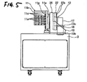
- a rotation output portion of the drive unit 12 As shown in FIGS. 5 and 8, for example, four rows of elongated holes 11c, 11c, ... are bored in a part of the turning arm 11, which is at the side of the second flat surface 11b. Then, bolts (not shown) are screwed into the elongated holes 11c, 11c, ....
- the turning arm 11 is fixed to the test head 5 by adjusting the position in the up-down direction of the turning arm to that of the test head 5.
- the drive unit 12 roughly includes the motor 16, the anterior reduction mechanism driven by the motor 16 to perform deceleration rotation, and the posterior reduction gear 26 serving as the posterior reduction mechanism connected to the anterior reduction mechanism.
- the posterior reduction mechanism may be constituted by a single reduction mechanism
- the drive unit 12 includes the anterior reduction mechanism which performs a first reduction of a rotation shaft speed of the motor 16, and also includes the posterior reduction mechanism that performed a second reduction of the rotation shaft speed reduced by the anterior reduction mechanism.
- the drive unit 12 is an example in which the reduction mechanism accommodated therein includes a planetary gear type reduction gear serving as the posterior reduction gear 26, and also includes a hypoid reduction gear 17 serving as the anterior reduction mechanism.
- Reference numeral 16 designates a motor which has a motor case 16a serving as a cylindrical stator, a motor shaft 16b that is rotatably supported and serves as an input shaft of the anterior reduction mechanism, and a hypoid pinion 16c formed at an end portion of the motor shaft 16b.
- the hypoid pinion 16c is plunged into a through hole 17c of a lower portion 17b of a hypoid reduction gear 17 (to be described later).
- the through hole 17c has a bearing 25 for the hypoid pinion 25 so as to allow the hypoid pinion 16c to be rotatable.
- Reference numeral 17 denotes a hypoid reduction gear serving as the anterior reduction mechanism which has a substantially rectangular box-like gear case 17a.
- a rear surface 17e of the gear case 17a is fixed to a front wall 27a of a connecting member 27 of the posterior reduction gear 26 with an engaging means 27c including a bolt and a hole.
- the lower portion 17b of the gear case 17a fixes the motor case 16a with bolts 18, 18.
- the hypoid reduction gear 17 has hypoid gears 19 that mesh with the hypoid pinion 16c.
- One of the hypoid gears 19 is connected to a rotor shaft 26a of the posterior reduction gear 26.
- the other hypoid gear 19 is connected to a pinion shaft 19a.
- the front end of the pinion shaft 19a is rotatably supported by the bearing 17d disposed on the front surface 17f of the gear case 17a serving as a bracket by means of the shaft.
- the hypoid gear 19 is made to be rotatable.
- the posterior reduction gear 26 has an cylindrical internally-toothed gear element 28 serving as a stationary case having a plurality of internally toothed pins 30c2 as internally toothed gears provided mainly in an inner circumferential portion.
- the posterior reduction gear 26 also has a pair of externally toothed gears 30c that are externally toothed gears having peritrochoidal forms, which mesh with the internally toothed pins 30c2 of the internally-toothed gear element 28, and that are adapted to eccentrically swing.
- the posterior reduction gear 26 also has a pinion gear 26b formed on the rotor shaft 26a serving as an rotation input portion, a shaft 29 serving as a rotation output portion, and a planetary gear type reduction gear 31 having main bearings 30b, 30b that serve as a pair of anterior and posterior roller bearings interposed between the internally-toothed gear element 28 and the shaft 29.
- the rotor shaft 26a is connected to one of the hypoid gears 19.
- the shaft 29 has a first endplate 29a, whose outer circumferential surface engages with an anterior main bearing 30a, and a second end plate 29c that has a pillar portion 29b loosely fit in the internally-toothed gear element 28 and that the outer circumferential surface of the second end plate 29c engages with a posterior main bearing 30b.
- a step-like cylindrical connecting member 27 is adj acently connected to the front surface of the internally-toothed gear element 28 with a bolt 27b.
- first end plate 29a and the second end plate 29c having the pillar portion 29b are adjacently connected to each other with a tapered pin (not shown), which is engaged in a shaft hole 29d formed in the first end plate 29a and the second end plate 29c, and a bolt 32.
- the anterior pinion gear 26b meshes with a spur gear 29g provided on a crankshaft 29f.
- the crankshaft 29f is rotatably supported by the first end plate 29a and the second end plate 29c and engages with the externally toothed gear 30c through a needle bearing 30c1.
- the rotation of the rotor shaft 26a is decelerated between the pinion gear 26b and the spur gear 29g and is transmitted to the crankshaft 29f.
- the rotation of the crankshaft 29f causes the externally toothed gear 30c to eccentrically swing, and also causes the shaft 29 to perform a decelerated output rotation.
- the reduction ratio of the posterior reduction gear 26 is set to be, for example, about 1/100.
- reference numeral 24 designates a bearing of the rotor shaft provided in the shaft center of the connecting member 27.
- the rotor shaft 26a is rotatably configured.
- the turning arm 11 is connected with a bolt (not shown) to the orthogonal flat surface 29i of the second end plate 29c, which is perpendicular to the axis A passing through the pivot of the turning arm 11.
- the turning arm 11 has a first flat surface 11a which is connected to the shaft 29 serving as the rotation output portion, i.e., to a flat surface of the second end plate 29c, and also has a second flat surface 11b that is connected to a heavy object such as the test head 5, and is perpendicular to the first flat surface 11a located at a place to a heavy object side than the axis A passing through the pivot.
- the turning arm 11 and the drive unit 12 are disposed within a width D of the test head 5 serving as the heavy object placed in the direction of the axis A passing through the pivot of the turning arm 11.
- a dot-dash-line C indicates the central position in the direction of the axis A of the heavy object, that is, the test head 5.
- a heavy object turning apparatus can be configured so that the heavy object turning apparatus is compact, that the distance between the center of gravity of the heavyobj ect such as the test head 5 and the pivot positioned on the axis A is decreased, and that the turning arm 11 and the drive unit 12 are positioned within a width D in the direction of the axis A passing through the heavy object.
- the central position C in the direction of the axis A passing through the pivot of the heavy object such as the test head 5 is set within a distance L from a point of intersection P at which a line B inclined to one of the pair of the main bearings 30b, which is placed at the perpendicular flat surface side of the rotation output portion, at a contact angle ⁇ (°) intersects with the axis A passing through the pivot. It was found that preferably, the contact angle ⁇ (°) is set to be 35° to 45°.
- the heavy object such as the test head 5 could be supported in a cantilevered manner. Also, the heavy object could stably be turned.
- FIG. 4 somewhat elongated bolt insertion holes. 11d, 11d, ... are provided around the periphery of the turning arm 11 in a part at the side of the first flat surface 11a thereof at desired intervals. Then, bolts 11e, 11e, ... shown in FIG. 5 are engaged and screwed in a shaft hole 29e.
- the heavy object is fixed to the turning arm 11 by positioning the heavy object in the direction of the drive unit 12 and adjusting the movement thereof in the up-down direction or the lateral direction.
- a concave portion 3b is formed in a top surface 3a of the stand 3 in the first embodiment of the heavy obj ect turning apparatus.
- a part of the drive unit 12, that is, the motor 16 is accommodated in the concave portion 3n or the hole.
- the motor 16 rotates at high speed to turn-drive the heavy object such as the test head 5 between a position indicated by a solid line and a position indicated by an imaginary line.
- the motor shaft 16b rotates at high speed inside the motor case 16a.
- the hypoid pinion 16c formed at an end portion of the motor shaft 16b engages with the hypoid gear 19 of the hypoid reduction gear 17 serving as the reduction mechanism.
- the torque of the motor is transmitted to the hypoid gear 19.
- a rotation operation of the hypoid gear 19 causes the rotor shaft 26a serving as a rotation output portion to perform a decelerated rotation.
- the rotation speed of the motor 16 is decreased by the hypoid reduction gear 17 to, for example, about (1/60) the original speed thereof.
- the rotor shaft 26a rotates at a speed reduced by the hypoid reduction gear 17 serving as the anterior reduction mechanism.
- the torque is transmitted to the spur gear 29g which meshes and engages with the pinion gear 26b formed at the rear end of the rotor shaft 26a.
- the rotation of the spur gear 29g causes the crankshaft 29f having a crank portion provided at the substantially center thereof to rotate while supported by the roller bearings 30e and 30d disposed adjacently on the front surface of the spur gear 29g.
- the torque of the crankshaft 29f is transmitted to the two rows of the adjacent externally-toothed gears 30c, 30c.
- the rotation operation of each of the externally-toothed gears 30c, 30c causes each of the first end plate 29a and the second end plate 29c having the pillar portion 29b of the shaft 29 serving as the rotation output portion to perform decelerated rotation.
- the second end plate 29c is adjacently connected to the first flat surface 11a of the turning arm 11 with bolts 11e, 11e, ..., and drives the turning arm 11 to decelerate.
- the heavy object such as the test head is driven to turn about 180° from the position indicated by the imaginary line to the position indicated by the solid line shown in FIG. 1.
- the test head 5 is electrically connected to the contact provided on the top surface of the probe card through the connecting ring 8.
- the probe apparatus 1 receives a test signal from the tester at the electrode of the semiconductor wafer set on the mount table through the test head 5 and the probe needle of the probe card. Then, an electrical test is performed on each IC chip of the semiconductor wafer.
- the posterior reduction gear 26 reduces the rotation speed of the hypoid reduction gear 17 serving as the anterior reduction gear to, for example, about (1/100) the original rotation speed thereof. Also, the posterior reduction gear 26 reduces the rotation speed of the motor 16 to, for example, about (1/6000) the original rotation speed thereof. Additionally, a high reduction ratio is obtained by a double reduction mechanism. Thus, the outside diameter of each of the anterior reduction gear 17, the posterior reduction gear 26 and the motor 16 can be reduced. Accordingly, the turning radius of the heavy object such as the test head 5 can be reduced still more.
- the value of the reduction ratio can be selected by appropriately setting the design dimensions or the shapes of the internal components or the members of the planetary gear type reduction gear 31. Also, the length in the direction of the axis A of the drive unit can be set to be short. Additionally, the drive unit 12 can be compacted.
- the heavy object turning apparatus can be constructed using only the anterior reduction gear, that is, only a single reduction gear by fixing the rotor shaft 26a to the turning arm 11.
- the drive unit 12 shown in these figures according to the second embodiment shown in the drawings is an example in which the reduction mechanism accommodated therein includes a planetary gear type reduction gear serving as the posterior reduction gear 26, and also includes a worm-geared reduction gear 20 serving as the anterior reduction mechanism.
- the worm-geared reduction gear 20 is a kind of the orthogonal axis reduction gear.
- Reference numeral 16 designates a motor which has a motor case 16a serving as a cylindrical stator, a motor shaft 16b that is rotatably supported and serves as an input shaft of the anterior reduction mechanism, and a worm pinion shaft 22 formed at an end portion of the motor shaft 16b.
- the worm pinion shaft 22 is inserted into a shaft hole 20c of a lower portion 20b of the worm-geared reduction gear 20 (to be described later).
- Reference numeral 20 designates the worm-geared reduction gear which has a substantially rectangular box-like gear case 20a.
- a rear surface 20e of the gear case 20a is fixed to a front wall 27a of a connecting member 27 of the posterior reduction gear 26 with an engaging means 27c or by the engagement of both members.
- the lower portion 20b of the gear case 20a fixes the motor case 16a.
- the worm-geared reduction gear 20 has a worm wheel 21 that meshes with the worm pinion 23.
- One side of the worm wheel 21 is connected to a rotor shaft 26a of the posterior reduction gear 26.
- the other side of the worm wheel 21 is connected to a worm wheel shaft 21a.
- the front end of the worm wheel 21a is rotatably supported by the bearing 20d disposed on the front surface 20f of the gear case 20a serving as a bracket by means of the shaft.
- the worm wheel 21 is made to be rotatable.
- the worm pinion shaft 22 is rotatably supported by disposing bearings 20h and 20i at an upper portion 20g and a lower portion 20b of the gear case 20a, respectively.
- the apparatus has what is called a self-lock function of surely transmitting the torque of the motor shaft 16b serving as the input shaft to the posterior reduction gear 26 and of preventing the torque of the posterior reduction gear 26 to the motor shaft 16b.
- stability in a maintenance work can be enhanced.
- the posterior reduction gear 26 has an cylindrical internally-toothed gear element 28 serving as a stationary case having a plurality of internally toothed pins 30c2 as internally toothed gears provided mainly in an inner circumferential portion.
- the posterior reduction gear 26 also has a pair of externally toothed gears 30c that are externally toothed gears having peritrochoidal forms, which mesh with the internally toothed pins 30c2 of the internally-toothed gear element 28, and that are adapted to eccentrically swing.
- the posterior reduction gear 26 also has a pinion gear 26b formed on the rotor shaft 2 6a serving as an rotation input portion, a shaft 29 serving as a rotation output portion, and a planetary gear type reduction gear 31 having main bearings 30b, 30b that serve as a pair of anterior and posterior roller bearings interposed between the internally-toothed gear element 28 and the shaft 29.
- the rotor shaft 26a is connected to one of the hypoid gears 19.
- the shaft 29 has a first endplate 29a, whose outer circumferential surface engages with an anterior main bearing 30a, and a second end plate 29c that has a pillar portion 29b loosely fit in the internally-toothed gear element 28 and that the outer circumferential surface of the second end plate 29c engages with a posterior main bearing 30b.
- a step-like cylindrical connecting member 27 is adjacently connected to the front surface of the internally-toothed gear element 28 with a bolt 27b.
- first end plate 29a and the second end plate 29c having the pillar portion 29b are adjacently connected to each other with a tapered pin (not shown), which is engaged in a shaft hole 29d formed in the first end plate 29a and the second end plate 29c, and a bolt 32.
- the anterior pinion gear 26b meshes with a spur gear 29g provided on a crankshaft 29f.
- the crankshaft 29f is rotatably supported by the first end plate 29a and the second end plate 29c and engages with the externally toothed gear 30c through a needle bearing 30cl.
- the rotation of the rotor shaft 26a is decelerated between the pinion gear 26b and the spur gear 29g and is transmitted to the crankshaft 29f.
- the rotation of the crankshaft 29f causes the externally toothed gear 30c to eccentrically swing, and also causes the shaft 29 to perform a decelerated output rotation.
- the reduction ratio of the posterior reduction gear 26 is set to be, for example, about 1/100
- the turning arm 11 is connected with a bolt (not shown) to the orthogonal flat surface 29i of the second end plate 29c, which is perpendicular to the axis A passing through the pivot of the turning arm 11.
- the turning arm 11 has a first flat surface 11a which is connected to the shaft 29 serving as the rotation output portion, i.e., to a flat surface of the second end plate 29c, and also has a second flat surface 11b that is connected to a heavy object such as the test head 5, and is perpendicular to the first flat surface 11a located at a place to a heavy object side than the axis A passing through the pivot.
- the turning arm 11 and the drive unit 12 are disposed within a width D of the test head 5 serving as the heavy object placed in the direction of the axis A passing through the pivot of the turning arm 11.
- a dot-dash-line C indicates the central position in the direction of the axis A of the heavy object, that is, the test head 5.
- a heavy object turning apparatus can be configured so that the heavy object turning apparatus is compact, that the distance between the center of gravity of the heavy object such as the test head 5 and the pivot positioned on the axis A is decreased, and that the turning arm 11 and the drive unit 12 are positioned within a width D in the direction of the axis A passing through the heavy object.
- the central position C in the direction of the axis A passing through the pivot of the heavy object such as the test head 5 is set within a distance L from a point of intersection P at which a line B inclined to one of the pair of the main bearings 30b, which is placed at the perpendicular flat surface side of the rotation output portion, at a contact angle ⁇ (°) intersects with the axis A passing through the pivot. It was found that preferably, the contact angle ⁇ (°) is set to be 35° to 45°.
- the heavy object such as the test head 5 could be supported in a cantilevered manner. Also, the heavy object could stably be turned.
- FIG. 6 somewhat elongated bolt insertion holes 11d, 11d, ..., are provided around the periphery of the turning arm 11 in a part at the side of the first flat surface 11a thereof at desired intervals. Then, bolts 11e, 11e, ... shown in FIG. 8 are engaged and screwed in a shaft hole 29e.
- the heavy object is fixed to the turning arm 11 by positioning the heavy object in the direction of the drive unit 12 and adjusting the movement thereof in the up-down direction or the lateral direction.
- a concave portion 3b is formed in a top surface 3a of the stand 3 in the second embodiment of the heavy object turning apparatus.
- a part of the drive unit 12, that is, the motor 16 is accommodated in the concave portion 3n or the hole.
- the motor 16 rotates at high speed to turn-drive the heavy object such as the test head 5 between a position indicated by a solid line and a position indicated by an imaginary line.
- the motor shaft 16b rotates at high speed inside the motor case 16a.
- the worm pinion 23 fixed to the worm pinion shaft 22 that is fixed to an end portion of the motor shaft 16b engages with the worm wheel 21 of the worm-geared reduction gear 20 serving as the reduction mechanism.
- the torque of the motor is transmitted to the worm wheel 21.
- a rotation operation of the worm wheel 21 causes the rotor shaft 26a serving as a rotation output portion to perform a decelerated rotation.
- the rotation speed of the motor 16 is decreased by the worm geaer reduction gear 20 to, for example, about (1/60) the original speed thereof.
- the rotor shaft 26a rotates at a speed reduced by the worm-geared reduction gear 20 serving as the anterior reduction mechanism.
- the torque is transmitted to the spur gear 29g which meshes and engages with the pinion gear 26b formed at the rear end of the rotor shaft 26a.
- the rotation of the spur gear 29g causes the crankshaft 29f having a crank portion provided at the substantially center thereof to rotate while supported by the roller bearings 30e and 30d disposed adjacently on the front surface of the spur gear 29g.
- the torque of the crankshaft 29f is transmitted to the two rows of the adjacent externally-toothed gears 30c, 30c.
- the rotation operation of each of the externally-toothed gears 30c, 30c causes each of the first end plate 29a and the second end plate 29c having the pillar portion 29b of the shaft 29 serving as the rotation output portion to perform decelerated rotation.
- the second endplate 29c is adjacently connected to the first flat surface 11a of the turning arm 11 with bolts 11e, 11e, ..., and drives the turning arm 11 to decelerate.
- the heavy object such as the test head is driven to turn about 180° from the position indicated by the imaginary line to the position indicated by the solid line shown in FIG. 1.
- the test head 5 is electrically connected to the contact provided on the top surface of the probe card through the connecting ring 8.
- the probe apparatus 1 receives a test signal from the tester at the electrode of the semiconductor wafer set on the mount table through the test head 5 and the probe needle of the probe card. Then, an electrical test is performed on each IC chip of the semiconductor wafer.
- the posterior reduction gear 26 reduces the rotation speed of the worm-geared reduction gear 20 serving as the anterior reduction gear to, for example, about (1/100) the original rotation speed thereof. Also, the posterior reduction gear 26 reduces the rotation speed of the motor 16 to, for example, about (1/6000) the original rotation speed thereof. Additionally, a high reduction ratio is obtained by a double reduction mechanism. Thus, the outside diameter of each of the anterior reduction gear 17, the posterior reduction gear 26 and the motor 16 can be reduced. Accordingly, the turning radius of the heavy object such as the test head 5 can be reduced still more.
- the value of the reduction ratio can be selected by appropriately setting the design dimensions or the shapes of the internal components or the members of the planetary gear type reduction gear 31. Also, the length in the direction of the axis A of the drive unit can be set to be short. Additionally, the drive unit 12 can be compacted.
- the heavy object turning apparatus can be constructed using only the anterior reduction gear, that is, only a single reduction gear by fixing the rotor shaft 26a to the turning arm 11.
Landscapes
- Physics & Mathematics (AREA)
- General Physics & Mathematics (AREA)
- Engineering & Computer Science (AREA)
- Computer Hardware Design (AREA)
- Microelectronics & Electronic Packaging (AREA)
- General Engineering & Computer Science (AREA)
- Retarders (AREA)
- Testing Or Measuring Of Semiconductors Or The Like (AREA)
- Tests Of Electronic Circuits (AREA)
- Testing Of Individual Semiconductor Devices (AREA)
- Gear Transmission (AREA)
- Manipulator (AREA)
Abstract
Description
- The present invention relates to a heavy object turning apparatus, which is applied to a probe apparatus or the like for measuring electric characteristics of a test target such as a semiconductor device, and which is configured to turn a heavy object, such as a test head.
- A conventional testing apparatus, for example, a probe apparatus comprises a loader unit, which has a conveyance mechanism adapted to convey semiconductor wafers one by one, and also comprises a prober unit adapted to continuously perform electrical tests on the semiconductor wafers. The prober unit has a mount table configured so that semiconductor wafers are transferred one by one between the mount table and the conveyance mechanism, a probe card disposed above the mount table, and a test head adapted to electrically interrupt between the probe card and a tester. The test head is fixed to a rotating shaft through a test head frame and hinges. The test head can turn around the rotating shaft, for example, 180° between a probe apparatus main body and a maintenance area. Recently, the test head has grown in size, so that the weight thereof has reached to 600 kg to 800 kg. To turn such a test head, which is a heavy object, amotor is frequently used. Additionally, the following
Patent Document 1 discloses a technique that is substantially the same as the above-described conventional technique.
Patent Document 1:JP-A-9-298224 - However, a structure of the conventional testing apparatus, such as the probe apparatus, in which the weight of a test head is supported by a motor and gears, have the following problems. That is, the gear for transmitting a driving force of the motor is enlarged. Also, the gears are arranged in a multistage configuration. Consequently, the configuration of the apparatus is complex. The cost of the apparatus is increased. Also, because the test head is turned around the enlarged gear, a turning radius cannot be reduced. The installation space for the probe apparatus is increased.
- The invention is accomplished to solve the above problems, and aims at providing a heavy object turning apparatus which is enabled to reduce the length in the direction of the axis of a rotation shaft of a drive unit without using an enlarged gear, and which has a small number of components.
- The invention can be implemented by the following configuration or means.
- (1) A heavy obj ect turning apparatus having a turning arm which is connected to a heavy object and is turned around a pivot, and a drive unit adapted to drive the turning arm to turn, characterized by comprising a planetary gear type reduction gear which has a stationary portion, a rotation input portion, a rotation output portion having an orthogonal flat surface perpendicular to the axis passing through the pivot, and a pair of roller bearings disposed between the stationary portion and the rotation output portion, an orthogonal axis reduction gear configured so that an output axis is on the axis of the planetary gear type reduction gear and that an input shaft is perpendicular to the axis, and a motor configured so that a motor shaft is disposed in parallel to the orthogonal flat surface, and
characterized in that the turning arm has a first flat surface connected to the orthogonal flat surface of the rotation output portion and also has a second flat surface which is connected to the heavy object and is placed to a heavy object side than the axis passing through the pivot and which has a second flat surface perpendicular to the first flat surface, and that the turning arm and the drive unit are disposed in a width in a direction of the axis passing through the pivot around which the heavy object is turned. - (2) Preferably, the heavy object turning apparatus according to the invention further comprises a support base, to which the drive unit is fixed, and a stand on which the support base is placed, and characterized in that a concave portion is formed in the stand, and that the motor is accommodated in the concave portion.
- (3) A heavy object turning apparatus having a turning arm which is connected to a heavy object and is turned around a pivot, and a drive unit adapted to drive the turning arm to turn. Preferably, the heavy object turning apparatus comprises a planetary gear type reduction gear which has a stationary portion, a rotation input portion, a rotation output portion having an orthogonal flat surface perpendicular to the axis passing through the pivot, and a pair of roller bearings disposed between the stationary portion and the rotation output portion, an orthogonal axis reduction gear configured so that an output axis is on the axis of the planetary gear type reduction gear and that an input shaft is perpendicular to the axis, and a motor configured so that a motor shaft is disposed in parallel to the orthogonal flat surface. Also, preferably, the turning arm has a first flat surface connected to the orthogonal flat surface of the rotation output portion and also has a second flat surface perpendicular to the first flat surface. Additionally, the turning arm and the drive unit are disposed in a width in a direction of the axis passing through the pivot around which the heavy object is turned.
- The heavy object turning apparatus according to the invention has the above configuration. Thus, the invention has the following advantages. That is, according to the invention, there is provided a heavy object turning apparatus having a turning arm which is connected to a heavy object and is turned around a pivot, and a drive unit adapted to drive the turning arm to turn. The heavy object turning apparatus features that the drive unit has a stationary portion, a rotation input portion, a rotation output portion having an orthogonal flat surface perpendicular to the axis passing through the pivot, and a planetary gear type reduction gear a having a pair of roller bearings disposed between the stationary portion and the rotation output portion, an orthogonal axis reduction gear configured so that an output axis is on the axis of the planetary gear type reduction gear and that an input shaft is perpendicular to the axis, and a motor configured so that a motor shaft is disposed in parallel to the orthogonal flat surface. Also, the heavy object turning apparatus features that the turning arm has a first flat surface connected to the orthogonal flat surface of the rotation output portion and also has a second flat surface perpendicular to the first flat surface which is connected to the heavy object and is placed to a heavy object side than the axis passing through the pivot, and the turning arm and the drive unit are disposed in the width of the heavy object in a direction of the axis passing through the pivot around which the heavy object is turned.
- With such a configuration, the heavy object turning apparatus can be configured so that the heavy object turning apparatus can be compact, that the length in the direction of the axis of the rotation shaft of the drive unit can be reduced, that a space portion can be assured in the direction of the axis of the drive unit, and that the turning arm and the drive unit are placed within a width in the direction of the axis passing through the pivot around which the heavy object is turned.
- According to the invention, there is provided the heavy obj ect turning apparatus that the heavy obj ect turning apparatus further comprises a support base, to which the drive unit is fixed, and a stand on which the support base is placed. Also, the heavy object turning apparatus features that a concave portion is formed in the stand, and that the motor is accommodated in the concave portion.
- With such a configuration, the invention has an advantage in that the heavy object turning apparatus can be compacted, in addition to the advantages of the invention described in
claim 1. - According to the invention, there is provided a heavy obj ect turning apparatus having a turning arm which is connected to a heavy object and is turned around a pivot, and a drive unit adapted to drive the turning arm to turn. The heavy object turning apparatus features that the drive unit has a stationary portion, a rotation input portion, a rotation output portion having an orthogonal flat surface perpendicular to the axis passing through the pivot, and a planetary gear type reduction gear having a pair of roller bearings disposed between the stationary portion and the rotation output portion, an orthogonal axis reduction gear configured so that an output axis is on the axis of the planetary gear type reduction gear and that an input shaft is perpendicular to the axis, and a motor configured so that a motor shaft is disposed in parallel to the orthogonal flat surface. The heavy object turning apparatus features that the turning arm has a first flat surface connected to the orthogonal flat surface of the rotation output portion and also has a second flat surface perpendicular to the first flat surface, and that the turning arm and the drive unit are disposed in the width of the heavy obj ect in a direction of the axis passing through the pivot around which the heavy object is turned.
- With such a configuration, the heavy object turning apparatus can be configured so that the heavy object turning apparatus can be compact, that the length in the direction of the axis of the rotation shaft of the drive unit can be reduced, that a space portion can be assured in the direction of the axis of the drive unit, and that the turning arm and the drive unit are placed within a width in the direction of the axis passing through the pivot around which the heavy object is turned.
-
- FIG. 1 is a front view illustrating a preferred example of a mode for implementing a heavy object turning apparatus according to the invention.
- FIG. 2 is a front view illustrating the preferred example of the mode for implementing the heavy object turning apparatus shown in FIG. 1 according to the invention.
- FIG. 3 is a side view, taken in the direction of an arrow E shown in FIG. 2, illustrating a stand and a drive unit in the preferred embodiment of the heavy object turning apparatus according to the invention.
- FIG. 4 is a vertically cross-sectional view illustrating a first embodiment of the heavy object turning apparatus according to the invention.
- FIG. 5 is a side view, taken in the direction of an arrow F shown in FIG. 1, illustrating the first embodiment of the heavy object turning apparatus according to the invention.
- FIG. 6 is a vertically cross-sectional view illustrating a second embodiment of the heavy object turning apparatus according to the invention.
- FIG. 7 is a cross-sectional view taken in the direction of arrows G-G shown in FIG. 6.
- FIG. 8 is a side view, taken in the direction of the arrow F shown in FIG. 1, illustrating the second embodiment of the heavy object turning apparatus according to the invention.
- Hereinafter, embodiments of a heavy object turning apparatus according to the invention are described below in detail with reference to the accompanying drawings.
- As shown in, for example, FIG. 1, a
probe apparatus 1 includes a probe apparatus body (hereunder referred to simply as an "apparatus body") 2 constituting a prober unit adapted to perform an electrical test on a test target, for example, a semiconductor wafer, a stand 3 disposed adjoining the left side of theapparatus body 2, atest head 5 serving as a heavy object adapted to be turned between theapparatus body 2 and a maintenance area 4 by the stand 3 nearly 180°, and a connecting ring 8. A semiconductor wafer conveyance apparatus 9 adapted to accommodate semiconductor wafers in units of cassettes and to load the semiconductor wafers from the cassette one by one and to unload the semiconductor wafers from the prober unit one by one is disposed at the right side of theapparatus body 2. - Also, a probe card (not shown) is provided in a central hole (not shown) of a
head plate 10 constituting the ceiling of theapparatus body 2. When thetest head 5 turns and is positioned above theapparatus body 2, thetest head 5 is electrically connected to a connection terminal provided on the top surface of the probe card through a connection ring 8. Thus, theprobe apparatus 1 is configured so that for example, a test signal from the tester is received at an electrode of a semiconductor wafer placed on a table through thetest head 5 and the probe card, and a probe needle, and that then, an electrical test is performed on each IC chip provided on the semiconductor wafer. - As shown in FIG. 2, the
test head 5 is fixed to a rotating shaft of adrive unit 12 through aturning arm 11 having a firstflat surface 11a and a secondflat surface 11b formed perpendicular to the firstflat surface 11a. Thus, thetest head 5 can turn through the rotating shaft. Theturning arm 11 turns around a pivot set on an axis A of the rotating shaft of thedrive unit 12. Thedrive unit 12 turn-drives theturning arm 11 and is provided on the top surface of the stand 3 through asupport base 13. Thesupport base 13 has a first attachingsurface 13a attached to thedrive unit 12 or to an attaching flat surface of a stationary portion of a planetary gear type reduction gear accommodated in thedrive unit 12, that is, a stationary case 28 (see FIG. 4). Thesupport base 13 also has a second attachingsurface 13b perpendicular to the first attachingsurface 13a, and a pair ofrib portions surface 13 to both outer end portions of the second attachingsurface 13b. - As shown in FIG. 1, cut
portions rib portions drive unit 12 or of the stationary portion of the planetary gear type reduction gear serving as a posterior stage reduction gear 26 (see FIG. 4), that is, of thestationary case 28. Because thecut portions rib portions stationary case 28 are cut short, the first attachingsurface 13a and the second attachingsurface 13b of thesupport base 13 can be reinforced by the pair of therib portions flat surface 11b and the axis A passing through the pivot, that is, without increasing the turning radius at which the heavy object such as the test head. Consequently, thesupport base 13 can be reinforced. - In FIG. 1,
reference numeral 14 designates an installation base on which the stand 3 accommodating a control unit is installed.Reference numerals bolts holes surface 13b and are somewhat elongated. Then, the second attachingsurface 13b is laterally positioned. Thus, thesupport base 13 is fixed on the stand 3. An orthogonalaxis reduction gear 6 serving as the anterior reduction gear is disposed in front of theposterior reduction gear 26. The orthogonalaxis reduction gear 6 has a configuration in which an output shaft of the orthogonalaxis reduction gear 6 is on the axis A of the planetary gear type reduction gear, and in which an input shaft of the orthogonalaxis reduction gear 6 is perpendicular to the axis A of the planetary gear type reduction gear. The orthogonalaxis reduction gear 6 is constituted by a hypoid reduction gear or a worm-geared reduction gear.Reference numeral 16 denotes a motor configured to be placed on the bottom surface of the orthogonalaxis reduction gear 6. The bottom portion of themotor 16 is interposed between thegear 6 and the stand 3. The motor shaft of themotor 16 is connected to a gear portion including the hypoid gear or a worm wheel of the orthogonalaxis reduction gear 6. Aconcave portion 3b including a hole is formed in thetop surface 3a of the stand 3. A part of thedrive unit 12, that is, themotor 16 is accommodated in theconcave portion 3b. - As shown in FIGS. 2 and 3, the first
flat surface 11a of the turningarm 11 is attached to a rotation output portion of thedrive unit 12. As shown in FIGS. 5 and 8, for example, four rows ofelongated holes arm 11, which is at the side of the secondflat surface 11b. Then, bolts (not shown) are screwed into theelongated holes arm 11 is fixed to thetest head 5 by adjusting the position in the up-down direction of the turning arm to that of thetest head 5. - Next, a first embodiment of the heavy object turning apparatus according to the invention is described below in detail with reference to FIGS. 4 and 5.
- The
drive unit 12 roughly includes themotor 16, the anterior reduction mechanism driven by themotor 16 to perform deceleration rotation, and theposterior reduction gear 26 serving as the posterior reduction mechanism connected to the anterior reduction mechanism. Although the posterior reduction mechanism may be constituted by a single reduction mechanism, thedrive unit 12 includes the anterior reduction mechanism which performs a first reduction of a rotation shaft speed of themotor 16, and also includes the posterior reduction mechanism that performed a second reduction of the rotation shaft speed reduced by the anterior reduction mechanism. - The
drive unit 12 according to the first embodiment shown in the drawings is an example in which the reduction mechanism accommodated therein includes a planetary gear type reduction gear serving as theposterior reduction gear 26, and also includes ahypoid reduction gear 17 serving as the anterior reduction mechanism. -
Reference numeral 16 designates a motor which has amotor case 16a serving as a cylindrical stator, amotor shaft 16b that is rotatably supported and serves as an input shaft of the anterior reduction mechanism, and ahypoid pinion 16c formed at an end portion of themotor shaft 16b. Thehypoid pinion 16c is plunged into a throughhole 17c of alower portion 17b of a hypoid reduction gear 17 (to be described later). The throughhole 17c has abearing 25 for thehypoid pinion 25 so as to allow thehypoid pinion 16c to be rotatable.Reference numeral 17 denotes a hypoid reduction gear serving as the anterior reduction mechanism which has a substantially rectangular box-like gear case 17a. Arear surface 17e of thegear case 17a is fixed to afront wall 27a of a connectingmember 27 of theposterior reduction gear 26 with an engagingmeans 27c including a bolt and a hole. Thelower portion 17b of thegear case 17a fixes themotor case 16a withbolts - The
hypoid reduction gear 17 has hypoid gears 19 that mesh with thehypoid pinion 16c. One of the hypoid gears 19 is connected to arotor shaft 26a of theposterior reduction gear 26. Theother hypoid gear 19 is connected to apinion shaft 19a. The front end of thepinion shaft 19a is rotatably supported by thebearing 17d disposed on thefront surface 17f of thegear case 17a serving as a bracket by means of the shaft. Thus, thehypoid gear 19 is made to be rotatable. - Next, the
posterior reduction gear 26 is described below. - The
posterior reduction gear 26 has an cylindrical internally-toothed gear element 28 serving as a stationary case having a plurality of internally toothed pins 30c2 as internally toothed gears provided mainly in an inner circumferential portion. Theposterior reduction gear 26 also has a pair of externallytoothed gears 30c that are externally toothed gears having peritrochoidal forms, which mesh with the internally toothed pins 30c2 of the internally-toothed gear element 28, and that are adapted to eccentrically swing. Theposterior reduction gear 26 also has apinion gear 26b formed on therotor shaft 26a serving as an rotation input portion, ashaft 29 serving as a rotation output portion, and a planetary geartype reduction gear 31 havingmain bearings toothed gear element 28 and theshaft 29. Therotor shaft 26a is connected to one of the hypoid gears 19. Theshaft 29 has afirst endplate 29a, whose outer circumferential surface engages with an anteriormain bearing 30a, and asecond end plate 29c that has apillar portion 29b loosely fit in the internally-toothed gear element 28 and that the outer circumferential surface of thesecond end plate 29c engages with a posteriormain bearing 30b. A step-likecylindrical connecting member 27 is adj acently connected to the front surface of the internally-toothed gear element 28 with abolt 27b. - Then, the
first end plate 29a and thesecond end plate 29c having thepillar portion 29b are adjacently connected to each other with a tapered pin (not shown), which is engaged in ashaft hole 29d formed in thefirst end plate 29a and thesecond end plate 29c, and abolt 32. Theanterior pinion gear 26b meshes with aspur gear 29g provided on acrankshaft 29f. Thecrankshaft 29f is rotatably supported by thefirst end plate 29a and thesecond end plate 29c and engages with the externallytoothed gear 30c through a needle bearing 30c1. The rotation of therotor shaft 26a is decelerated between thepinion gear 26b and thespur gear 29g and is transmitted to thecrankshaft 29f. The rotation of thecrankshaft 29f causes the externallytoothed gear 30c to eccentrically swing, and also causes theshaft 29 to perform a decelerated output rotation. The reduction ratio of theposterior reduction gear 26 is set to be, for example, about 1/100. - Incidentally, in the drawings,
reference numeral 24 designates a bearing of the rotor shaft provided in the shaft center of the connectingmember 27. Therotor shaft 26a is rotatably configured. - Thus, the turning
arm 11 is connected with a bolt (not shown) to the orthogonalflat surface 29i of thesecond end plate 29c, which is perpendicular to the axis A passing through the pivot of the turningarm 11. Also, the turningarm 11 has a firstflat surface 11a which is connected to theshaft 29 serving as the rotation output portion, i.e., to a flat surface of thesecond end plate 29c, and also has a secondflat surface 11b that is connected to a heavy object such as thetest head 5, and is perpendicular to the firstflat surface 11a located at a place to a heavy object side than the axis A passing through the pivot. As shown in FIG. 2, the turningarm 11 and thedrive unit 12 are disposed within a width D of thetest head 5 serving as the heavy object placed in the direction of the axis A passing through the pivot of the turningarm 11. - Incidentally, a dot-dash-line C indicates the central position in the direction of the axis A of the heavy object, that is, the
test head 5. Thus, a heavy object turning apparatus can be configured so that the heavy object turning apparatus is compact, that the distance between the center of gravity of the heavyobj ect such as thetest head 5 and the pivot positioned on the axis A is decreased, and that the turningarm 11 and thedrive unit 12 are positioned within a width D in the direction of the axis A passing through the heavy object. The central position C in the direction of the axis A passing through the pivot of the heavy object such as thetest head 5 is set within a distance L from a point of intersection P at which a line B inclined to one of the pair of themain bearings 30b, which is placed at the perpendicular flat surface side of the rotation output portion, at a contact angle α (°) intersects with the axis A passing through the pivot. It was found that preferably, the contact angle α (°) is set to be 35° to 45°. - With this configuration, the heavy object such as the
test head 5 could be supported in a cantilevered manner. Also, the heavy object could stably be turned. - As shown in FIG. 4, somewhat elongated bolt insertion holes. 11d, 11d, ... are provided around the periphery of the turning
arm 11 in a part at the side of the firstflat surface 11a thereof at desired intervals. Then,bolts shaft hole 29e. The heavy object is fixed to the turningarm 11 by positioning the heavy object in the direction of thedrive unit 12 and adjusting the movement thereof in the up-down direction or the lateral direction. Although described in "BestMode for Carrying Out the Invention", similarly, aconcave portion 3b is formed in atop surface 3a of the stand 3 in the first embodiment of the heavy obj ect turning apparatus. A part of thedrive unit 12, that is, themotor 16 is accommodated in the concave portion 3n or the hole.
Next, an operation of the first embodiment of the heavy object turning apparatus according to the invention is described below. - The
motor 16 rotates at high speed to turn-drive the heavy object such as thetest head 5 between a position indicated by a solid line and a position indicated by an imaginary line. Thus, themotor shaft 16b rotates at high speed inside themotor case 16a. Thehypoid pinion 16c formed at an end portion of themotor shaft 16b engages with thehypoid gear 19 of thehypoid reduction gear 17 serving as the reduction mechanism. The torque of the motor is transmitted to thehypoid gear 19. A rotation operation of thehypoid gear 19 causes therotor shaft 26a serving as a rotation output portion to perform a decelerated rotation. Then, the rotation speed of themotor 16 is decreased by thehypoid reduction gear 17 to, for example, about (1/60) the original speed thereof. - Subsequently, the torque of the
hypoid gear 19, whose rotation speed has been reduced to a first level as above described, is transmitted to therotor shaft 26a serving as the rotation input portion. Therotor shaft 26a rotates at a speed reduced by thehypoid reduction gear 17 serving as the anterior reduction mechanism. Then, the torque is transmitted to thespur gear 29g which meshes and engages with thepinion gear 26b formed at the rear end of therotor shaft 26a. The rotation of thespur gear 29g causes thecrankshaft 29f having a crank portion provided at the substantially center thereof to rotate while supported by theroller bearings spur gear 29g. The torque of thecrankshaft 29f is transmitted to the two rows of the adjacent externally-toothed gears toothed gears first end plate 29a and thesecond end plate 29c having thepillar portion 29b of theshaft 29 serving as the rotation output portion to perform decelerated rotation.
Additionally, thesecond end plate 29c is adjacently connected to the firstflat surface 11a of the turningarm 11 withbolts arm 11 to decelerate. - Thus, the heavy object such as the test head is driven to turn about 180° from the position indicated by the imaginary line to the position indicated by the solid line shown in FIG. 1. Then, the
test head 5 is electrically connected to the contact provided on the top surface of the probe card through the connecting ring 8. Theprobe apparatus 1 receives a test signal from the tester at the electrode of the semiconductor wafer set on the mount table through thetest head 5 and the probe needle of the probe card. Then, an electrical test is performed on each IC chip of the semiconductor wafer. - Thus, the
posterior reduction gear 26 reduces the rotation speed of thehypoid reduction gear 17 serving as the anterior reduction gear to, for example, about (1/100) the original rotation speed thereof. Also, theposterior reduction gear 26 reduces the rotation speed of themotor 16 to, for example, about (1/6000) the original rotation speed thereof. Additionally, a high reduction ratio is obtained by a double reduction mechanism. Thus, the outside diameter of each of theanterior reduction gear 17, theposterior reduction gear 26 and themotor 16 can be reduced. Accordingly, the turning radius of the heavy object such as thetest head 5 can be reduced still more. The value of the reduction ratio can be selected by appropriately setting the design dimensions or the shapes of the internal components or the members of the planetary geartype reduction gear 31. Also, the length in the direction of the axis A of the drive unit can be set to be short. Additionally, thedrive unit 12 can be compacted. - According to the invention, the heavy object turning apparatus can be constructed using only the anterior reduction gear, that is, only a single reduction gear by fixing the
rotor shaft 26a to the turningarm 11. - Next, a second embodiment of the heavy object turning apparatus according to the invention is described below in detail with reference to FIGS. 6 through 8.
- The
drive unit 12 shown in these figures according to the second embodiment shown in the drawings is an example in which the reduction mechanism accommodated therein includes a planetary gear type reduction gear serving as theposterior reduction gear 26, and also includes a worm-gearedreduction gear 20 serving as the anterior reduction mechanism. The worm-gearedreduction gear 20 is a kind of the orthogonal axis reduction gear. -
Reference numeral 16 designates a motor which has amotor case 16a serving as a cylindrical stator, amotor shaft 16b that is rotatably supported and serves as an input shaft of the anterior reduction mechanism, and aworm pinion shaft 22 formed at an end portion of themotor shaft 16b. Theworm pinion shaft 22 is inserted into ashaft hole 20c of alower portion 20b of the worm-geared reduction gear 20 (to be described later).
Reference numeral 20 designates the worm-geared reduction gear which has a substantially rectangular box-like gear case 20a. Arear surface 20e of thegear case 20a is fixed to afront wall 27a of a connectingmember 27 of theposterior reduction gear 26 with an engagingmeans 27c or by the engagement of both members. Thelower portion 20b of thegear case 20a fixes themotor case 16a.
The worm-gearedreduction gear 20 has aworm wheel 21 that meshes with theworm pinion 23. One side of theworm wheel 21 is connected to arotor shaft 26a of theposterior reduction gear 26. The other side of theworm wheel 21 is connected to aworm wheel shaft 21a. The front end of theworm wheel 21a is rotatably supported by thebearing 20d disposed on thefront surface 20f of thegear case 20a serving as a bracket by means of the shaft. Thus, theworm wheel 21 is made to be rotatable. - . Incidentally, the
worm pinion shaft 22 is rotatably supported by disposingbearings 20h and 20i at anupper portion 20g and alower portion 20b of thegear case 20a, respectively. Incidentally, the apparatus has what is called a self-lock function of surely transmitting the torque of themotor shaft 16b serving as the input shaft to theposterior reduction gear 26 and of preventing the torque of theposterior reduction gear 26 to themotor shaft 16b. Thus, stability in a maintenance work can be enhanced. - Next, the
posterior reduction gear 26 is described below. - The
posterior reduction gear 26 has an cylindrical internally-toothed gear element 28 serving as a stationary case having a plurality of internally toothed pins 30c2 as internally toothed gears provided mainly in an inner circumferential portion. Theposterior reduction gear 26 also has a pair of externallytoothed gears 30c that are externally toothed gears having peritrochoidal forms, which mesh with the internally toothed pins 30c2 of the internally-toothed gear element 28, and that are adapted to eccentrically swing. Theposterior reduction gear 26 also has apinion gear 26b formed on therotor shaft 2 6a serving as an rotation input portion, ashaft 29 serving as a rotation output portion, and a planetary geartype reduction gear 31 havingmain bearings toothed gear element 28 and theshaft 29. Therotor shaft 26a is connected to one of the hypoid gears 19. Theshaft 29 has afirst endplate 29a, whose outer circumferential surface engages with an anteriormain bearing 30a, and asecond end plate 29c that has apillar portion 29b loosely fit in the internally-toothed gear element 28 and that the outer circumferential surface of thesecond end plate 29c engages with a posteriormain bearing 30b. A step-likecylindrical connecting member 27 is adjacently connected to the front surface of the internally-toothed gear element 28 with abolt 27b. - Then, the
first end plate 29a and thesecond end plate 29c having thepillar portion 29b are adjacently connected to each other with a tapered pin (not shown), which is engaged in ashaft hole 29d formed in thefirst end plate 29a and thesecond end plate 29c, and abolt 32. Theanterior pinion gear 26b meshes with aspur gear 29g provided on acrankshaft 29f. Thecrankshaft 29f is rotatably supported by thefirst end plate 29a and thesecond end plate 29c and engages with the externallytoothed gear 30c through a needle bearing 30cl. The rotation of therotor shaft 26a is decelerated between thepinion gear 26b and thespur gear 29g and is transmitted to thecrankshaft 29f. The rotation of thecrankshaft 29f causes the externallytoothed gear 30c to eccentrically swing, and also causes theshaft 29 to perform a decelerated output rotation. The reduction ratio of theposterior reduction gear 26 is set to be, for example, about 1/100. - Thus, the turning
arm 11 is connected with a bolt (not shown) to the orthogonalflat surface 29i of thesecond end plate 29c, which is perpendicular to the axis A passing through the pivot of the turningarm 11. Also, the turningarm 11 has a firstflat surface 11a which is connected to theshaft 29 serving as the rotation output portion, i.e., to a flat surface of thesecond end plate 29c, and also has a secondflat surface 11b that is connected to a heavy object such as thetest head 5, and is perpendicular to the firstflat surface 11a located at a place to a heavy object side than the axis A passing through the pivot. As shown in FIG. 2, the turningarm 11 and thedrive unit 12 are disposed within a width D of thetest head 5 serving as the heavy object placed in the direction of the axis A passing through the pivot of the turningarm 11. - Incidentally, a dot-dash-line C indicates the central position in the direction of the axis A of the heavy object, that is, the
test head 5. Thus, a heavy object turning apparatus can be configured so that the heavy object turning apparatus is compact, that the distance between the center of gravity of the heavy object such as thetest head 5 and the pivot positioned on the axis A is decreased, and that the turningarm 11 and thedrive unit 12 are positioned within a width D in the direction of the axis A passing through the heavy object. - Incidentally, the central position C in the direction of the axis A passing through the pivot of the heavy object such as the
test head 5 is set within a distance L from a point of intersection P at which a line B inclined to one of the pair of themain bearings 30b, which is placed at the perpendicular flat surface side of the rotation output portion, at a contact angle α (°) intersects with the axis A passing through the pivot. It was found that preferably, the contact angle α (°) is set to be 35° to 45°. - With this configuration, the heavy object such as the
test head 5 could be supported in a cantilevered manner. Also, the heavy object could stably be turned. - As shown in FIG. 6, somewhat elongated
bolt insertion holes arm 11 in a part at the side of the firstflat surface 11a thereof at desired intervals. Then,bolts shaft hole 29e. The heavy object is fixed to the turningarm 11 by positioning the heavy object in the direction of thedrive unit 12 and adjusting the movement thereof in the up-down direction or the lateral direction. Although described in "Best Mode for Carrying Out the Invention", similarly, aconcave portion 3b is formed in atop surface 3a of the stand 3 in the second embodiment of the heavy object turning apparatus. A part of thedrive unit 12, that is, themotor 16 is accommodated in the concave portion 3n or the hole. - Next, an operation of the second embodiment of the heavy object turning apparatus according to the invention is described below.
- The
motor 16 rotates at high speed to turn-drive the heavy object such as thetest head 5 between a position indicated by a solid line and a position indicated by an imaginary line. Thus, themotor shaft 16b rotates at high speed inside themotor case 16a. Theworm pinion 23 fixed to theworm pinion shaft 22 that is fixed to an end portion of themotor shaft 16b engages with theworm wheel 21 of the worm-gearedreduction gear 20 serving as the reduction mechanism. The torque of the motor is transmitted to theworm wheel 21. A rotation operation of theworm wheel 21 causes therotor shaft 26a serving as a rotation output portion to perform a decelerated rotation. Then, the rotation speed of themotor 16 is decreased by the wormgeaer reduction gear 20 to, for example, about (1/60) the original speed thereof. - Subsequently, the torque of the
worm wheel 21, whose rotation speed has been reduced to a first level as above described, is transmitted to therotor shaft 26a serving as the rotation input portion. Therotor shaft 26a rotates at a speed reduced by the worm-gearedreduction gear 20 serving as the anterior reduction mechanism. Then, the torque is transmitted to thespur gear 29g which meshes and engages with thepinion gear 26b formed at the rear end of therotor shaft 26a. The rotation of thespur gear 29g causes thecrankshaft 29f having a crank portion provided at the substantially center thereof to rotate while supported by theroller bearings spur gear 29g. The torque of thecrankshaft 29f is transmitted to the two rows of the adjacent externally-toothed gears toothed gears first end plate 29a and thesecond end plate 29c having thepillar portion 29b of theshaft 29 serving as the rotation output portion to perform decelerated rotation. Additionally, thesecond endplate 29c is adjacently connected to the firstflat surface 11a of the turningarm 11 withbolts arm 11 to decelerate. - Thus, the heavy object such as the test head is driven to turn about 180° from the position indicated by the imaginary line to the position indicated by the solid line shown in FIG. 1. Then, the
test head 5 is electrically connected to the contact provided on the top surface of the probe card through the connecting ring 8. Theprobe apparatus 1 receives a test signal from the tester at the electrode of the semiconductor wafer set on the mount table through thetest head 5 and the probe needle of the probe card. Then, an electrical test is performed on each IC chip of the semiconductor wafer. - Thus, the
posterior reduction gear 26 reduces the rotation speed of the worm-gearedreduction gear 20 serving as the anterior reduction gear to, for example, about (1/100) the original rotation speed thereof. Also, theposterior reduction gear 26 reduces the rotation speed of themotor 16 to, for example, about (1/6000) the original rotation speed thereof.
Additionally, a high reduction ratio is obtained by a double reduction mechanism. Thus, the outside diameter of each of theanterior reduction gear 17, theposterior reduction gear 26 and themotor 16 can be reduced. Accordingly, the turning radius of the heavy object such as thetest head 5 can be reduced still more. The value of the reduction ratio can be selected by appropriately setting the design dimensions or the shapes of the internal components or the members of the planetary geartype reduction gear 31. Also, the length in the direction of the axis A of the drive unit can be set to be short. Additionally, thedrive unit 12 can be compacted. - According to the invention, the heavy object turning apparatus can be constructed using only the anterior reduction gear, that is, only a single reduction gear by fixing the
rotor shaft 26a to the turningarm 11.
Claims (3)
- A heavy object turning apparatus having a turning arm which is connected to a heavy object and is turned around a pivot, and a drive unit adapted to drive said turning arm to turn, characterized in that said drive gear has a stationary portion, a rotation input portion, a rotation output portion having an orthogonal flat surface perpendicular to the axis passing through the pivot, and a planetary gear type reduction gear having a pair of roller bearings disposed between the stationary portion and the rotation output portion, an orthogonal axis reduction gear configured so that an output axis is on the axis of said planetary gear type reduction gear and that an input shaft is perpendicular to the axis, and a motor configured so that a motor shaft is disposed in parallel to the orthogonal flat surface, and
said turning arm has a first flat surface connected to the orthogonal flat surface of said rotation output portion and a second flat surface perpendicular to the first flat surface which is connected to said heavy obj ect and is placed to a heavy object side than the axis passing through the pivot , and that said turning arm and said drive unit are disposed in the width of the heavy object in a direction of the axis passing through the pivot around which said heavy object is turned. - The heavy object turning apparatus according to claim 1, characterized by further comprising a support base, to which said drive unit is fixed, and a stand on which said support base is placed, and wherein a concave portion is formed in said stand, and that said motor is accommodated in said concave portion.
- A heavy obj ect turning apparatus having a turning arm which is connected to a heavy object and is turned around a pivot, and a drive unit adapted to drive said turning arm to turn, characterized in that said drive unit has a stationary portion, a rotation input portion, a rotation output portion having an orthogonal flat surface perpendicular to the axis passing through the pivot, and a planetary gear type reduction gear having pair of roller bearings disposed between the stationary portion and the rotation output portion, an orthogonal axis reduction gear configured so that an output axis is on the axis of said planetary gear type reduction gear and that an input shaft is perpendicular to the axis, and a motor configured so that a motor shaft is disposed in parallel to the orthogonal flat surface, and said turning arm has a first flat surface connected to the orthogonal flat surface of said rotation output portion and also has a second flat surface perpendicular to the first flat surface, and said turning arm and said drive unit are disposed in the width of the heavy obj ect in a direction of the axis passing through the pivot around which said heavy object is turned.
Applications Claiming Priority (3)
| Application Number | Priority Date | Filing Date | Title |
|---|---|---|---|
| JP2004255107 | 2004-09-02 | ||
| JP2005169492A JP4793809B2 (en) | 2004-09-02 | 2005-06-09 | Heavy object turning mechanism |
| PCT/JP2005/016120 WO2006025529A1 (en) | 2004-09-02 | 2005-09-02 | Turning device for heavy object |
Publications (1)
| Publication Number | Publication Date |
|---|---|
| EP1785735A1 true EP1785735A1 (en) | 2007-05-16 |
Family
ID=36000174
Family Applications (1)
| Application Number | Title | Priority Date | Filing Date |
|---|---|---|---|
| EP05781386A Withdrawn EP1785735A1 (en) | 2004-09-02 | 2005-09-02 | Heavy object turning apparatus |
Country Status (6)
| Country | Link |
|---|---|
| US (1) | US8007389B2 (en) |
| EP (1) | EP1785735A1 (en) |
| JP (1) | JP4793809B2 (en) |
| KR (1) | KR101057708B1 (en) |
| TW (1) | TWI387029B (en) |
| WO (1) | WO2006025529A1 (en) |
Families Citing this family (10)
| Publication number | Priority date | Publication date | Assignee | Title |
|---|---|---|---|---|
| JP5408840B2 (en) * | 2006-12-15 | 2014-02-05 | ナブテスコ株式会社 | 2-axis rotary positioner |
| JP5075074B2 (en) * | 2008-09-25 | 2012-11-14 | ナブテスコ株式会社 | Rotation drive unit and semiconductor inspection apparatus having rotation drive unit |
| JP6081985B2 (en) | 2012-03-16 | 2017-02-15 | 住友重機械工業株式会社 | Heavy swivel swivel |
| JP5985385B2 (en) * | 2012-12-27 | 2016-09-06 | 住友重機械工業株式会社 | Gear motor |
| CN104373542A (en) * | 2014-10-24 | 2015-02-25 | 浙江恒丰泰减速机制造有限公司 | Locating transmission mechanism |
| JP5967510B1 (en) * | 2015-03-24 | 2016-08-10 | 株式会社東京精密 | Prober |
| KR101835199B1 (en) * | 2016-02-12 | 2018-03-07 | 현대로보틱스주식회사 | Robot for transferring substrate |
| JP6650807B2 (en) * | 2016-03-28 | 2020-02-19 | 東京エレクトロン株式会社 | Test head turning mechanism and inspection device |
| TWI692644B (en) * | 2019-06-18 | 2020-05-01 | 旺矽科技股份有限公司 | Electronic device needle measuring device |
| CN116877673B (en) * | 2023-08-31 | 2023-11-21 | 中国科学院长春光学精密机械与物理研究所 | Heavy-duty overturning transmission mechanism |
Family Cites Families (11)
| Publication number | Priority date | Publication date | Assignee | Title |
|---|---|---|---|---|
| CA1244855A (en) | 1985-01-18 | 1988-11-15 | Kazuyuki Matsumoto | Robot arm drive apparatus of industrial robot |
| JPS63224649A (en) * | 1987-03-11 | 1988-09-19 | Komatsu Ltd | geared motor |
| US5203748A (en) * | 1990-05-09 | 1993-04-20 | Canon Kabushiki Kaisha | Rotary driving system and robot operating thereon |
| US5293107A (en) * | 1993-02-24 | 1994-03-08 | Fanuc Robotics North America, Inc. | Motorized rotary joint and method of constructing a modular robot utilizing same |
| JPH09109082A (en) * | 1995-10-12 | 1997-04-28 | Fanuc Ltd | Joint structure of industrial robot |
| JP3329430B2 (en) * | 1996-04-09 | 2002-09-30 | 株式会社安川電機 | Industrial robot wrist mechanism |
| JP3266509B2 (en) * | 1996-05-09 | 2002-03-18 | 東京エレクトロン株式会社 | Heavy object turning device and inspection device |
| JP2001221828A (en) * | 1999-11-29 | 2001-08-17 | Ando Electric Co Ltd | Connector for test head |
| MY144519A (en) | 2000-03-01 | 2011-09-30 | Intest Corp | Vertical counter balanced test head manipulator |
| JP4312484B2 (en) * | 2003-03-26 | 2009-08-12 | 住友重機械工業株式会社 | Swing intermeshing planetary gear unit |
| JP4715747B2 (en) | 2004-03-25 | 2011-07-06 | 東京エレクトロン株式会社 | Heavy object swivel mechanism in probe device |
-
2005
- 2005-06-09 JP JP2005169492A patent/JP4793809B2/en not_active Expired - Lifetime
- 2005-08-31 TW TW094129848A patent/TWI387029B/en not_active IP Right Cessation
- 2005-09-02 EP EP05781386A patent/EP1785735A1/en not_active Withdrawn
- 2005-09-02 KR KR1020077005128A patent/KR101057708B1/en not_active Expired - Lifetime
- 2005-09-02 US US11/574,444 patent/US8007389B2/en active Active
- 2005-09-02 WO PCT/JP2005/016120 patent/WO2006025529A1/en not_active Ceased
Non-Patent Citations (1)
| Title |
|---|
| See references of WO2006025529A1 * |
Also Published As
| Publication number | Publication date |
|---|---|
| US8007389B2 (en) | 2011-08-30 |
| US20080298948A1 (en) | 2008-12-04 |
| KR20070056082A (en) | 2007-05-31 |
| JP4793809B2 (en) | 2011-10-12 |
| KR101057708B1 (en) | 2011-08-18 |
| JP2006098388A (en) | 2006-04-13 |
| TW200620521A (en) | 2006-06-16 |
| WO2006025529A1 (en) | 2006-03-09 |
| TWI387029B (en) | 2013-02-21 |
Similar Documents
| Publication | Publication Date | Title |
|---|---|---|
| US8007389B2 (en) | Heavy object turning apparatus | |
| JP3726693B2 (en) | Antenna device | |
| US5066135A (en) | Rotatable vortexing turntable | |
| US7794350B2 (en) | Turning device for heavy object | |
| US6262570B1 (en) | Probe apparatus | |
| JP3266509B2 (en) | Heavy object turning device and inspection device | |
| CN101010595A (en) | Heavy Object Turning Equipment | |
| EP0758608B1 (en) | Power drive unit for aircraft cargo handling systems | |
| CN100429757C (en) | Turning device for heavy object | |
| CN114705932A (en) | EMC on-load testing device | |
| US11614145B2 (en) | Gear device | |
| CN2603401Y (en) | Automatic electronic component detection equipment | |
| CN218885430U (en) | Reduction box aging test frame | |
| JPH11108740A (en) | Load cell-type weighing device equipped with calibration function | |
| JP2001221682A (en) | Raising and lowering device for built-in weight | |
| JPH0828669A (en) | Backlash adjustment mechanism for hypoid gear power transmission | |
| KR100242931B1 (en) | Camera pan tilts with low power | |
| TW201810475A (en) | Test head pivot mechanism and inspection apparatus | |
| CN114135490B (en) | Centrifugal pump | |
| CN220728920U (en) | Rotary furnace door device and oxidation furnace equipment | |
| JP2003106413A (en) | Reduction gear under thrust load | |
| SU1732229A1 (en) | Rig for testing spring s-shaped posts | |
| KR20080054326A (en) | Inspection, measurement and work equipment using direct drive motors | |
| SU591740A1 (en) | Stand for investigating loaders | |
| JPH05134769A (en) | Torque control type actuator |
Legal Events
| Date | Code | Title | Description |
|---|---|---|---|
| PUAI | Public reference made under article 153(3) epc to a published international application that has entered the european phase |
Free format text: ORIGINAL CODE: 0009012 |
|
| 17P | Request for examination filed |
Effective date: 20070222 |
|
| AK | Designated contracting states |
Kind code of ref document: A1 Designated state(s): AT BE BG CH CY CZ DE DK EE ES FI FR GB GR HU IE IS IT LI LT LU LV MC NL PL PT RO SE SI SK TR |
|
| RIN1 | Information on inventor provided before grant (corrected) |
Inventor name: KAMEDA, NOBUHIROC/O YAMANASHI PLANT, TOKYO ELECTRO Inventor name: YUDATE, TOSHIHIRO,C/O TSU PLANT, NABTESCO CORP. Inventor name: AKIYAMA, SHUJIC/O YAMANASHI PLANT, TOKYO ELECTRON Inventor name: YAMADA, HIROSHIC/O YAMANASHI PLANT, TOKYO ELECTRON |
|
| DAX | Request for extension of the european patent (deleted) | ||
| STAA | Information on the status of an ep patent application or granted ep patent |
Free format text: STATUS: THE APPLICATION HAS BEEN WITHDRAWN |
|
| 18W | Application withdrawn |
Effective date: 20090803 |