EP1785272A1 - Lightweight panel and method for manufacturing the same - Google Patents
Lightweight panel and method for manufacturing the same Download PDFInfo
- Publication number
- EP1785272A1 EP1785272A1 EP05020836A EP05020836A EP1785272A1 EP 1785272 A1 EP1785272 A1 EP 1785272A1 EP 05020836 A EP05020836 A EP 05020836A EP 05020836 A EP05020836 A EP 05020836A EP 1785272 A1 EP1785272 A1 EP 1785272A1
- Authority
- EP
- European Patent Office
- Prior art keywords
- recess
- rod
- lightweight
- attachment surface
- shaped element
- Prior art date
- Legal status (The legal status is an assumption and is not a legal conclusion. Google has not performed a legal analysis and makes no representation as to the accuracy of the status listed.)
- Granted
Links
Images

Classifications
-
- B—PERFORMING OPERATIONS; TRANSPORTING
- B32—LAYERED PRODUCTS
- B32B—LAYERED PRODUCTS, i.e. PRODUCTS BUILT-UP OF STRATA OF FLAT OR NON-FLAT, e.g. CELLULAR OR HONEYCOMB, FORM
- B32B7/00—Layered products characterised by the relation between layers; Layered products characterised by the relative orientation of features between layers, or by the relative values of a measurable parameter between layers, i.e. products comprising layers having different physical, chemical or physicochemical properties; Layered products characterised by the interconnection of layers
- B32B7/04—Interconnection of layers
- B32B7/12—Interconnection of layers using interposed adhesives or interposed materials with bonding properties
-
- B—PERFORMING OPERATIONS; TRANSPORTING
- B29—WORKING OF PLASTICS; WORKING OF SUBSTANCES IN A PLASTIC STATE IN GENERAL
- B29C—SHAPING OR JOINING OF PLASTICS; SHAPING OF MATERIAL IN A PLASTIC STATE, NOT OTHERWISE PROVIDED FOR; AFTER-TREATMENT OF THE SHAPED PRODUCTS, e.g. REPAIRING
- B29C67/00—Shaping techniques not covered by groups B29C39/00 - B29C65/00, B29C70/00 or B29C73/00
- B29C67/0044—Shaping techniques not covered by groups B29C39/00 - B29C65/00, B29C70/00 or B29C73/00 for shaping edges or extremities
-
- B—PERFORMING OPERATIONS; TRANSPORTING
- B32—LAYERED PRODUCTS
- B32B—LAYERED PRODUCTS, i.e. PRODUCTS BUILT-UP OF STRATA OF FLAT OR NON-FLAT, e.g. CELLULAR OR HONEYCOMB, FORM
- B32B3/00—Layered products comprising a layer with external or internal discontinuities or unevennesses, or a layer of non-planar form; Layered products having particular features of form
- B32B3/02—Layered products comprising a layer with external or internal discontinuities or unevennesses, or a layer of non-planar form; Layered products having particular features of form characterised by features of form at particular places, e.g. in edge regions
- B32B3/08—Layered products comprising a layer with external or internal discontinuities or unevennesses, or a layer of non-planar form; Layered products having particular features of form characterised by features of form at particular places, e.g. in edge regions characterised by added members at particular parts
-
- B—PERFORMING OPERATIONS; TRANSPORTING
- B32—LAYERED PRODUCTS
- B32B—LAYERED PRODUCTS, i.e. PRODUCTS BUILT-UP OF STRATA OF FLAT OR NON-FLAT, e.g. CELLULAR OR HONEYCOMB, FORM
- B32B3/00—Layered products comprising a layer with external or internal discontinuities or unevennesses, or a layer of non-planar form; Layered products having particular features of form
- B32B3/10—Layered products comprising a layer with external or internal discontinuities or unevennesses, or a layer of non-planar form; Layered products having particular features of form characterised by a discontinuous layer, i.e. formed of separate pieces of material
- B32B3/12—Layered products comprising a layer with external or internal discontinuities or unevennesses, or a layer of non-planar form; Layered products having particular features of form characterised by a discontinuous layer, i.e. formed of separate pieces of material characterised by a layer of regularly- arranged cells, e.g. a honeycomb structure
-
- E—FIXED CONSTRUCTIONS
- E04—BUILDING
- E04C—STRUCTURAL ELEMENTS; BUILDING MATERIALS
- E04C2/00—Building elements of relatively thin form for the construction of parts of buildings, e.g. sheet materials, slabs, or panels
- E04C2/30—Building elements of relatively thin form for the construction of parts of buildings, e.g. sheet materials, slabs, or panels characterised by the shape or structure
- E04C2/34—Building elements of relatively thin form for the construction of parts of buildings, e.g. sheet materials, slabs, or panels characterised by the shape or structure composed of two or more spaced sheet-like parts
- E04C2/36—Building elements of relatively thin form for the construction of parts of buildings, e.g. sheet materials, slabs, or panels characterised by the shape or structure composed of two or more spaced sheet-like parts spaced apart by transversely-placed strip material, e.g. honeycomb panels
- E04C2/365—Building elements of relatively thin form for the construction of parts of buildings, e.g. sheet materials, slabs, or panels characterised by the shape or structure composed of two or more spaced sheet-like parts spaced apart by transversely-placed strip material, e.g. honeycomb panels by honeycomb structures
-
- E—FIXED CONSTRUCTIONS
- E04—BUILDING
- E04C—STRUCTURAL ELEMENTS; BUILDING MATERIALS
- E04C2/00—Building elements of relatively thin form for the construction of parts of buildings, e.g. sheet materials, slabs, or panels
- E04C2/30—Building elements of relatively thin form for the construction of parts of buildings, e.g. sheet materials, slabs, or panels characterised by the shape or structure
- E04C2/38—Building elements of relatively thin form for the construction of parts of buildings, e.g. sheet materials, slabs, or panels characterised by the shape or structure with attached ribs, flanges, or the like, e.g. framed panels
- E04C2/386—Building elements of relatively thin form for the construction of parts of buildings, e.g. sheet materials, slabs, or panels characterised by the shape or structure with attached ribs, flanges, or the like, e.g. framed panels with a frame of unreconstituted or laminated wood
-
- B—PERFORMING OPERATIONS; TRANSPORTING
- B29—WORKING OF PLASTICS; WORKING OF SUBSTANCES IN A PLASTIC STATE IN GENERAL
- B29C—SHAPING OR JOINING OF PLASTICS; SHAPING OF MATERIAL IN A PLASTIC STATE, NOT OTHERWISE PROVIDED FOR; AFTER-TREATMENT OF THE SHAPED PRODUCTS, e.g. REPAIRING
- B29C65/00—Joining or sealing of preformed parts, e.g. welding of plastics materials; Apparatus therefor
- B29C65/48—Joining or sealing of preformed parts, e.g. welding of plastics materials; Apparatus therefor using adhesives, i.e. using supplementary joining material; solvent bonding
-
- B—PERFORMING OPERATIONS; TRANSPORTING
- B29—WORKING OF PLASTICS; WORKING OF SUBSTANCES IN A PLASTIC STATE IN GENERAL
- B29C—SHAPING OR JOINING OF PLASTICS; SHAPING OF MATERIAL IN A PLASTIC STATE, NOT OTHERWISE PROVIDED FOR; AFTER-TREATMENT OF THE SHAPED PRODUCTS, e.g. REPAIRING
- B29C65/00—Joining or sealing of preformed parts, e.g. welding of plastics materials; Apparatus therefor
- B29C65/56—Joining or sealing of preformed parts, e.g. welding of plastics materials; Apparatus therefor using mechanical means or mechanical connections, e.g. form-fits
- B29C65/565—Joining or sealing of preformed parts, e.g. welding of plastics materials; Apparatus therefor using mechanical means or mechanical connections, e.g. form-fits involving interference fits, e.g. force-fits or press-fits
-
- B—PERFORMING OPERATIONS; TRANSPORTING
- B29—WORKING OF PLASTICS; WORKING OF SUBSTANCES IN A PLASTIC STATE IN GENERAL
- B29C—SHAPING OR JOINING OF PLASTICS; SHAPING OF MATERIAL IN A PLASTIC STATE, NOT OTHERWISE PROVIDED FOR; AFTER-TREATMENT OF THE SHAPED PRODUCTS, e.g. REPAIRING
- B29C66/00—General aspects of processes or apparatus for joining preformed parts
- B29C66/50—General aspects of joining tubular articles; General aspects of joining long products, i.e. bars or profiled elements; General aspects of joining single elements to tubular articles, hollow articles or bars; General aspects of joining several hollow-preforms to form hollow or tubular articles
- B29C66/51—Joining tubular articles, profiled elements or bars; Joining single elements to tubular articles, hollow articles or bars; Joining several hollow-preforms to form hollow or tubular articles
- B29C66/53—Joining single elements to tubular articles, hollow articles or bars
- B29C66/534—Joining single elements to open ends of tubular or hollow articles or to the ends of bars
- B29C66/5346—Joining single elements to open ends of tubular or hollow articles or to the ends of bars said single elements being substantially flat
-
- B—PERFORMING OPERATIONS; TRANSPORTING
- B29—WORKING OF PLASTICS; WORKING OF SUBSTANCES IN A PLASTIC STATE IN GENERAL
- B29C—SHAPING OR JOINING OF PLASTICS; SHAPING OF MATERIAL IN A PLASTIC STATE, NOT OTHERWISE PROVIDED FOR; AFTER-TREATMENT OF THE SHAPED PRODUCTS, e.g. REPAIRING
- B29C66/00—General aspects of processes or apparatus for joining preformed parts
- B29C66/70—General aspects of processes or apparatus for joining preformed parts characterised by the composition, physical properties or the structure of the material of the parts to be joined; Joining with non-plastics material
- B29C66/72—General aspects of processes or apparatus for joining preformed parts characterised by the composition, physical properties or the structure of the material of the parts to be joined; Joining with non-plastics material characterised by the structure of the material of the parts to be joined
- B29C66/725—General aspects of processes or apparatus for joining preformed parts characterised by the composition, physical properties or the structure of the material of the parts to be joined; Joining with non-plastics material characterised by the structure of the material of the parts to be joined being hollow-walled or honeycombs
- B29C66/7254—General aspects of processes or apparatus for joining preformed parts characterised by the composition, physical properties or the structure of the material of the parts to be joined; Joining with non-plastics material characterised by the structure of the material of the parts to be joined being hollow-walled or honeycombs honeycomb structures
-
- B—PERFORMING OPERATIONS; TRANSPORTING
- B29—WORKING OF PLASTICS; WORKING OF SUBSTANCES IN A PLASTIC STATE IN GENERAL
- B29L—INDEXING SCHEME ASSOCIATED WITH SUBCLASS B29C, RELATING TO PARTICULAR ARTICLES
- B29L2007/00—Flat articles, e.g. films or sheets
- B29L2007/002—Panels; Plates; Sheets
-
- B—PERFORMING OPERATIONS; TRANSPORTING
- B32—LAYERED PRODUCTS
- B32B—LAYERED PRODUCTS, i.e. PRODUCTS BUILT-UP OF STRATA OF FLAT OR NON-FLAT, e.g. CELLULAR OR HONEYCOMB, FORM
- B32B2305/00—Condition, form or state of the layers or laminate
- B32B2305/02—Cellular or porous
- B32B2305/024—Honeycomb
-
- B—PERFORMING OPERATIONS; TRANSPORTING
- B32—LAYERED PRODUCTS
- B32B—LAYERED PRODUCTS, i.e. PRODUCTS BUILT-UP OF STRATA OF FLAT OR NON-FLAT, e.g. CELLULAR OR HONEYCOMB, FORM
- B32B2607/00—Walls, panels
Abstract
Description
Die Erfindung betrifft eine Leichtbauplatte mit einem plattenförmigen Werkstück, das zwei dünnwandige Decklagen und mindestens einer zwischen den Decklagen angeordneten und mit diesen verklebten Kernlage mit geringerer Dichte, vorzugsweise aus leichtem Füllmaterial aufweist, und ein Verfahren zu Verarbeiten einer Leichtbauplatte.The invention relates to a lightweight board with a plate-shaped workpiece having two thin-walled cover layers and at least one arranged between the cover layers and bonded thereto core layer with lower density, preferably made of lightweight filler, and a method for processing a lightweight board.
Leichtbauplatten der eingangs genannten Art werden beispielsweise zur Herstellung von Zimmertüren, Möbelelementen, Paneelelementen oder dergleichen eingesetzt. Die dünnwandigen Decklagen bestehen dabei meist aus einer Furnier-, Kunststoff- oder Metallplattenlage geringer Wandstärke, die auf die Außenseite der Kernlage aus leichtem Füllmaterial aufgeklebt wird.Lightweight panels of the type mentioned are used for example for the production of room doors, furniture elements, panel elements or the like. The thin-walled cover layers usually consist of a veneer, plastic or metal plate layer of low wall thickness, which is adhered to the outside of the core layer of lightweight filler.
Unter einer derartigen Kernlage wird eine Füllmateriallage verstanden, die weitgehend aus miteinander verbundenen Stegen besteht und Hohlräume verschiedenster Form enthält. Bevorzugt sind dabei waben- oder rohrartige Strukturen, die - bezogen auf das Volumen - ein extrem niedriges Gewicht besitzen.Under such a core layer is a Füllmateriallage understood, which largely consists of interconnected webs and contains cavities of various forms. Preference is given to honeycomb or tubular structures which - based on the volume - have an extremely low weight.
Um den Leichtbauplatten ausreichende Stabilität und einen Kantenabschluss zu verleihen, werden in den Randbereichen der Platten meist Riegel zwischen die dünnwandigen Decklagen eingebracht. Eine derartige, bekannte Leichbauplatte ist in Fig. 4 schematisch dargestellt. Ein entsprechendes Herstellungsverfahren für Leichtbauplatten ist beispielsweise in der
Um die Variabilität zu erhöhen, ist es bekannt, großformatige plattenförmige Werkstücke mit zwei dünnwandigen Decklagen und einer Kernlage ohne Rahmenriegel vorzufertigen und bei Bedarf in entsprechenden Abmessungen zuzusägen, um abschließend Rahmenriegel an den freien Rändern der zugesägten Platten zwischen den Decklagen vorzusehen. Ein derartiges Verfahren ist beispielsweise in der Zeitschrift BM, Heft 9, 2004, S. 48 bis 49 offenbart. Bei diesem Verfahren wird die Kernlage ausgefräst, und die Rahmenriegel ("Blindkante") werden zwischen den Decklagen eingeleimt.In order to increase the variability, it is known to prefabricate large-sized plate-shaped workpieces with two thin-walled cover layers and a core layer without frame latch and sawed if necessary in appropriate dimensions to finally provide frame latch at the free edges of the sawn plates between the cover layers. Such a method is disclosed for example in the magazine BM,
Allerdings hat sich gezeigt, dass der auf die Decklagen aufgebrachte Leim beim Einschieben der Rahmenriegel aufgrund der engen Abmessungstoleranzen durch die Rahmenriegel "abgezogen" wird und sich nicht angemessen auf der Verbindungsoberfläche zwischen Rahmenriegeln und Decklagen verteilt. Hierdurch ergibt sich eine unzureichende Verbindung zwischen Rahmenriegeln und Decklagen, wodurch die Stabilität und Dauerhaftigkeit der Leichtbauplatte beeinträchtigt wird.However, it has been found that the glue applied to the cover layers is "pulled off" during insertion of the frame latches due to the tight dimensional tolerances through the frame latches and does not distribute adequately on the connection surface between frame latches and cover layers. This results in an insufficient connection between frame bolts and cover layers, whereby the stability and durability of the lightweight board is impaired.
Es ist daher Aufgabe der vorliegenden Erfindung, eine Leichtbauplatte mit verbesserter Stabilität und Dauerhaftigkeit sowie ein Verfahren zu deren Verarbeitung bereitzustellen.It is therefore an object of the present invention to provide a lightweight board with improved stability and durability, and a method for its processing.
Diese Aufgabe wird erfindungsgemäß durch ein Verfahren mit den Merkmalen von Anspruch 1 und eine Leichtbauplatte mit den Merkmalen von Anspruch 9 gelöst. Besonders vorteilhafte Weiterbildungen der Erfindung sind in den abhängigen Ansprüchen angegeben.This object is achieved by a method with the features of
Der Erfindung liegt der Gedanke zugrunde, die Qualität und Gleichmäßigkeit der Leimverbindung zwischen den dünnwandigen Decklagen und dem stabförmigen Element, das beispielsweise als Rahmenriegel ausgebildet sein kann, zu verbessern. Zu diesem Zweck ist erfindungsgemäß vorgesehen, dass bei einem gattungsgemäßen Verfahren die Ausnehmung derart in das Werkstück eingebracht wird, dass die Anbringfläche mindestens eine Vertiefung aufweist.The invention is based on the idea to improve the quality and uniformity of the glue joint between the thin-walled cover layers and the rod-shaped element, which may be formed, for example, as a frame latch. For this purpose, the invention provides that in a generic method, the recess is introduced into the workpiece such that the attachment surface has at least one recess.
Die Erfinder haben überraschenderweise festgestellt, dass das Vorsehen mindestens einer Vertiefung in einer Anbringfläche die Gleichmäßigkeit der Leimverteilung im Bereich der Anbringfläche deutlich verbessert, so dass sich eine erheblich bessere Verbindung zwischen den Decklagen und dem jeweiligen stabförmigen Element (insbesondere Rahmenriegel) ergibt. Auf diese Weise lässt sich durch das erfindungsgemäße Verfahren eine Leichtbauplatte mit deutlich gesteigerter Stabilität und Dauerhaftigkeit herstellen. Darüber hinaus lässt sich auch die Maßhaltigkeit der Leichtbauplatte verbessern, da der Leim zumindest teilweise in die mindestens eine Vertiefung ausweichen kann und so die Passung zwischen Riegeln und Decklagen kaum beeinträchtigt.The inventors have surprisingly found that the provision of at least one recess in a mounting surface significantly improves the uniformity of the glue distribution in the region of the attachment surface, resulting in a significantly better connection between the cover layers and the respective rod-shaped element (in particular frame tie). In this way can be produced by the inventive method a lightweight board with significantly increased stability and durability. In addition, the dimensional accuracy of the lightweight board can be improved because the glue can at least partially dodge into the at least one depression and thus hardly affects the fit between bars and cover layers.
Dabei ist zu beachten, dass die mindestens eine Vertiefung im Rahmen der vorliegenden Erfindung alternativ oder zusätzlich auch im dem jeweiligen stabförmigen Element derart vorgesehen werden kann, dass sie der entsprechenden Anbringfläche zugewandt ist. Ebenso ist es im Rahmen der vorliegenden Erfindung denkbar, dass das stabförmige Element einen sich verjüngenden Querschnitt besitzt, wobei die schmalere Seite des Querschnitts auf der Innenseite der Ausnehmung angeordnet wird. Hierdurch lassen sich unterschiedlichste Hohlräume zwischen dem stabförmigen Element und den jeweiligen Decklagen zur Aufnahme und Verteilung des Haftmittels schaffen, um die oben genannten Vorteile zu erzielen bzw. zu verstärken.It should be noted that the at least one recess in the context of the present invention may alternatively or additionally also be provided in the respective rod-shaped element such that it faces the corresponding attachment surface. It is also conceivable in the context of the present invention that the rod-shaped element has a tapered cross section, wherein the narrower side of the cross section is arranged on the inside of the recess. In this way, very different cavities between the rod-shaped element and the respective cover layers for receiving and distributing the adhesive can be created in order to achieve or enhance the abovementioned advantages.
Gemäß einer Weiterbildung der vorliegenden Erfindung wird in der mindestens einen Vertiefung Haftmittel vorgesehen. Die mindestens eine Vertiefung dient auf diese Weise als Haftmittelreservoir, durch welches das Haftmittel beim Einführen eines stabförmigen Elements in die jeweilige Ausnehmung mit Haftmittel bestrichen wird, sodass sich eine gleichmäßige Verteilung des Haftmittels ergibt.According to one embodiment of the present invention, adhesive is provided in the at least one depression. The at least one depression serves in this way as an adhesive reservoir, by means of which the adhesive is coated with adhesive upon insertion of a rod-shaped element into the respective recess, so that a uniform distribution of the adhesive results.
Die mindestens eine Vertiefung kann im Rahmen der vorliegenden Erfindung auf unterschiedlichste Art und Weise vorgesehen sein. Gemäß einer Weiterbildung der vorliegenden Erfindung ist jedoch vorgesehen, dass die mindestens eine Vertiefung mindestens eine Längsnut umfasst, die sich in der Längsrichtung des stabförmigen Elements kontinuierlich oder diskontinuierlich erstreckt. Hierdurch wird sichergestellt, dass das stabförmige Element entlang seiner gesamten Länge in ausreichendem Maße mit Haftmittel versehen wird, sodass die Stabilität und Dauerhaftigkeit der hergestellten Leichtbauplatte weiter gesteigert werden kann.The at least one recess can be provided in the context of the present invention in various ways. According to a development of the present invention, however, it is provided that the at least one recess comprises at least one longitudinal groove which extends continuously or discontinuously in the longitudinal direction of the rod-shaped element. This ensures that the rod-shaped element is provided with sufficient adhesive along its entire length, so that the stability and durability of the lightweight board produced can be further increased.
Alternativ oder zusätzlich ist gemäß einer Weiterbildung der Erfindung vorgesehen, dass die mindestens eine Vertiefung in der Richtung des Einführens des stabförmigen Elements mit einer zunehmenden Tiefe und bevorzugt danach mit einer abnehmenden Tiefe vorgesehen wird. Hierdurch ergibt sich, wie Versuche gezeigt haben, ein besonders geeignetes Reservoir für das Haftmittel, das einen guten Verbund zwischen den dünnwandigen Decklagen und dem jeweiligen stabförmigen Element ermöglicht.Alternatively or additionally, it is provided according to a development of the invention that the at least one recess in the direction of insertion of the rod-shaped element with an increasing depth and preferably thereafter provided with a decreasing depth. This results, as experiments have shown, a particularly suitable reservoir for the adhesive, which allows a good bond between the thin-walled cover layers and the respective rod-shaped element.
Um zusätzlich zu der Haftverbindung zwischen den dünnwandigen Decklagen und dem jeweiligen stabförmigen Element auch einen guten Formschluss zwischen diesen Bauteilen zu erzielen, ist gemäß einer Weiterbildung der vorliegenden Erfindung vorgesehen, dass die Anbringfläche benachbart zum freien Rand des Werkstücks und/oder benachbart zu der Kernlage einen Bereich aufweist, der frei von Vertiefungen ist. An diesem vertiefungsfreien Bereich kann das jeweilige stabförmige Element flächig anliegen, sodass es stabil gehalten wird und sich eine innige Verbindung ergibt.In order to achieve a good fit between these components in addition to the adhesive bond between the thin-walled cover layers and the respective rod-shaped element is provided according to a development of the present invention that the attachment surface adjacent to the free edge of the workpiece and / or adjacent to the core layer a Has area that is free of depressions. At this recess-free area, the respective rod-shaped element can lie flat, so that it is held stable and results in an intimate connection.
In diesem Zusammenhang ist gemäß einer Weiterbildung der vorliegenden Erfindung vorgesehen, dass die Anbringfläche derart ausgebildet wird, dass sie aus dem Bereich der mindestens einen Vertiefung mit geringem Spiel an dem stabförmigen Element anliegt. Dabei ergibt sich eine besonders stabile und dauerhafte Leichtbauplatte, wenn die Anbringfläche an dem stabförmigen Element im Presssitz anliegt.In this context, it is provided according to a development of the present invention that the attachment surface is formed such that it rests from the region of the at least one recess with little play on the rod-shaped element. This results in a particularly stable and durable lightweight board when the mounting surface rests against the rod-shaped element in a press fit.
Im Rahmen der vorliegenden Erfindung ist es prinzipiell möglich, die als Ausgangsmaterial dienenden, plattenförmigen Werkstücke von vornherein in einer gewünschten Größe vorzufertigen. Ein besonders wirtschaftliches Verfahren erhält man jedoch, wenn die plattenförmigen Werkstücke gemäß einer Weiterbildung der vorliegenden Erfindung großformatig vorproduziert werden, und anschließend die jeweiligen plattenförmigen Werkstücke mit der gewünschten Größe aus dem großformatigen plattenförmigen Werkstück herausgesägt werden.In the context of the present invention, it is possible in principle to prefabricate the plate-shaped workpieces serving as starting material from the outset in a desired size. However, a particularly economical method is obtained if the plate-shaped workpieces are pre-produced large format according to a development of the present invention, and then the respective plate-shaped workpieces are sawn out with the desired size from the large-sized plate-shaped workpiece.
Gemäß einer weiteren Zielrichtung stellt die vorliegende Erfindung eine Leichtbauplatte mit den Merkmalen von Anspruch 8 bereit, die durch das Vorsehen mindestens einer Vertiefung in einer Anbringfläche eine sehr hohe Stabilität und Dauerhaftigkeit besitzt. Vorteilhafte Ausgestaltungen dieser Leichtbauplatte sind in den Ansprüchen 9 bis 13 definiert, wobei im Hinblick auf die hierdurch erzielten Vorteile und Wirkungen auf die obigen Ausführungen verwiesen werden kann.According to a further aspect, the present invention provides a lightweight panel having the features of claim 8, which has a very high stability and durability by providing at least one recess in a mounting surface. Advantageous embodiments of this lightweight board are defined in
- Fig. 1Fig. 1
- zeigt schematisch eine Schnittansicht einer Leichtbauplatte gemäß einer ersten Ausführungsform der vorliegenden Erfindung;schematically shows a sectional view of a lightweight panel according to a first embodiment of the present invention;
- Fig. 2Fig. 2
- zeigt schematisch eine Schnittansicht einer Leichtbauplatte gemäß einer zweiten bevorzugten Ausführungsform der vorliegenden Erfindung;schematically shows a sectional view of a lightweight panel according to a second preferred embodiment of the present invention;
- Fig. 3Fig. 3
- zeigt schematisch eine Schnittansicht einer Leichtbauplatte gemäß einer dritten bevorzugten Ausführungsform der vorliegenden Erfindung.schematically shows a sectional view of a lightweight panel according to a third preferred embodiment of the present invention.
- Fig. 4Fig. 4
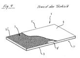
- zeigt schematisch eine Perspektivansicht einer vorbekannten Leichbauplatte.schematically shows a perspective view of a previously known Leichbauplatte.
Bevorzugte Ausführungsformen der vorliegenden Erfindung werden nachfolgend ausführlich unter Bezugnahme auf die begleitenden Zeichnungen beschrieben.Preferred embodiments of the present invention will be described below in detail with reference to the accompanying drawings.
Der prinzipielle Aufbau einer bekannten Leichtbauplatte 1, auf welche die vorliegende Erfindung aufbaut, ist in Fig. 4 schematisch in einer Perspektivansicht dargestellt. Die Leichtbauplatte 1 umfasst zwei dünnwandige Decklagen 3, 5, die beispielsweise aus Holz, Holzaustauschstoffen, Kunststoff, Metall oder anderen geeigneten Materialien bestehen können. Die Decklagen können auch mehrschichtig ausgebildet sein. Zwischen den dünnwandigen Decklagen 3, 5 ist eine Kernlage 7 mit geringerer Dichte, vorzugsweise aus leichtem Füllmaterial angeordnet und mit den Decklagen verklebt. Die Kernlage 7 besitzt in der vorliegenden Ausführungsform eine wabenartige Struktur und wird in den meisten Anwendungsfällen einen hohen Hohlraumanteil besitzen, obgleich die vorliegende Erfindung nicht hierauf beschränkt ist. Vielmehr kann die Kernlage auch aus einem gleichen oder ähnlichen Material wie die Decklagen bestehen und lediglich eine geringere Dichte besitzen. Unter dieser Voraussetzung ist auch eine integrale Ausbildung von Decklagen und Kernlage möglich.The basic structure of a known
An den freien Rändern 1' besitzt die Leichtbauplatte 1 zwischen den Decklagen 3, 5 jeweils Rahmenriegel 9' die beispielsweise aus Holz, Holzaustauschstoffen, Kunststoff, Metall oder dergleichen bestehen und mit den dünnwandigen Decklagen 3, 5 über ein Haftmittel verbunden sind.At the free edges 1 'has the
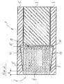
Die vorliegende Erfindung befasst sich insbesondere mit der Ausbildung der Verbindungen der Riegel 9' mit den dünnwandigen Decklagen 3, 5 im Bereich einer Anbringfläche. Eine erste bevorzugte Ausführungsform der vorliegenden Erfindung ist in Fig. 1 schematisch in einer Schnittansicht dargestellt. Die in Fig. 1 teilweise gezeigte Leichtbauplatte 1 basiert auf der in Fig. 4 gezeigten Leichtbauplatte, sodass auf eine wiederholte Beschreibung gleicher Bauteile verzichtet wird und nur die Unterschiede zum Stand der Technik herausgearbeitet werden.The present invention is particularly concerned with the formation of the connections of the bars 9 'with the thin-
Wie in Fig. 1 zu erkennen ist, weisen die dünnwandigen Decklagen 3, 5 auf ihrer Innenseite jeweils eine Anbringfläche 3', 5' auf, die dazu vorgesehen ist, mit dem jeweiligen Riegel 9' über ein Haftmittel 13 verbunden zu werden. In jeder der Anbringflächen 3', 5' sind in der vorliegenden Ausführungsform drei Längsnuten 15' vorgesehen, die sich in der Längsrichtung des Riegels 9' (d.h. senkrecht zur Zeichenebene in Fig. 1) erstrecken. Dabei können die Längsnuten 15' kontinuierlich oder diskontinuierlich ausgebildet sein. Zwischen bzw. neben den Längsnuten 15' sind Vertiefungen 15 vorgesehen, die eine geringere Tiefe als die Längsnuten 15' besitzen. In der vorliegenden Ausführungsform besitzt nur der mit X gekennzeichnete Bereich der Anbringflächen 3', 5' keinerlei Vertiefungen 15 oder 15'. Dabei ist der Bereich X derart ausgelegt, dass er an dem Riegel 9' anliegt, und zwar bevorzugt im Presssitz.As can be seen in Fig. 1, the thin-walled cover layers 3, 5 on its inner side in each case an attachment surface 3 ', 5', which is provided with the respective latch 9 'to be connected via an adhesive 13. In each of the attachment surfaces 3 ', 5' three longitudinal grooves 15 'are provided in the present embodiment, which extend in the longitudinal direction of the bolt 9' (ie perpendicular to the plane in Fig. 1). In this case, the longitudinal grooves 15 'may be formed continuously or discontinuously. Between or adjacent to the longitudinal grooves 15 '
In den Vertiefungen 15 und den Längsnuten 15' ist ein Haftmittel 13 vorgesehen, bei dem es sich beispielsweise um einen EVA-, PVAc- oder PU-Klebestoff handeln kann.In the
Die Herstellung der in Fig. 1 gezeigten Leichtbauplatte vollzieht sich beispielsweise wie folgt. Zunächst wird ein plattenförmiges Werkstück bereitgestellt, das zwei dünnwandige Decklagen 3, 5 und eine zwischen diesen angeordnete und mit diesen verklebte Kernlage 7 aus leichtem Füllmaterial umfasst. Dieses plattenförmige Werkstück kann einerseits von vornherein mit den gewünschten Abmessungen gefertigt werden, oder kann aus einem großformatigen Werkstück mit den gewünschten Abmessungen herausgesägt werden.The manufacture of the lightweight panel shown in Fig. 1 takes place, for example, as follows. First, a plate-shaped workpiece is provided which comprises two thin-walled cover layers 3, 5 and a
Anschließend wird eine Ausnehmung 9 in eine Schmalfläche 1' bzw. in alle Schmalflächen 1' des plattenförmigen Werkstücks eingebracht, beispielsweise durch Fräsen. Dabei reicht die Ausnehmung 9 in der vorliegenden Ausführungsform sowohl in die Kernlage 7 als auch in die beiden dünnwandigen Decklagen 3, 5 hinein und wird derart vorgesehen, dass die Anbringflächen 3', 5' jeweils mit den Vertiefungen 15 und Längsnuten 15' ausgestattet sind.Subsequently, a
Nun wird das Haftmittel 13 zumindest in den Längsnuten 15' vorgesehen, die in der vorliegenden Ausführungsform als "Haftmittelreservoir" dienen, um anschließend den jeweiligen Riegel 9' in die Ausnehmung 9 einzuführen, und zwar in Fig. 1 in einer Richtung von links nach rechts. Dabei streicht die Oberfläche des Riegels 9' an dem Haftmittel 13 entlang, das zumindest in den Längsnuten 15' vorgesehen ist. Auf diese Weise wird die Oberfläche des Riegels 9' mit dem Haftmittel 13 bestrichen, sodass sich eine gleichmäßige Haftmittelverteilung zwischen dem Riegel 9 und den dünnwandigen Decklagen 3, 5 im Bereich der Anbringfläche 3', 5' ergibt. Darüber hinaus stellt sich auch ein Formschluss zwischen ausgehärtetem Haftmittel und dünnwandigen Decklagen ein, was die Festigkeit der Haftverbindungen weiter verbessert. Hierdurch ergibt sich in Kombination mit dem bevorzugten Presssitz im Bereich X eine besonders stabile, maßhaltige und dauerhafte Leichtbauplatte.Now, the adhesive 13 is provided at least in the longitudinal grooves 15 ', which serve as "adhesive reservoir" in the present embodiment, to then insert the respective latch 9' in the
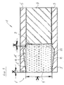
Eine zweite bevorzugte Ausführungsform der erfindungsgemäßen Leichtbauplatte 1 ist in Fig. 2 ebenfalls in einer teilweisen Schnittansicht dargestellt. Die in Fig. 2 gezeigte Ausführungsform unterscheidet sich von der in Fig. 1 gezeigten Ausführungsform durch die Ausgestaltung der Vertiefungen 15. Diese sind in der vorliegenden Ausführungsform derart ausgebildet, dass sie in der Richtung des Einführens des Riegels 9' keilförmig mit einer zunehmenden Tiefe ausgebildet sind, wobei die vorliegende Erfindung nicht auf eine Keilform beschränkt ist und vielfältige Formen mit kontinuierlich oder diskontinuierlich zunehmender Tiefe möglich sind. Dabei ist zu beachten, dass die Vertiefungen 15 in Fig. 2 (und ebenso in der nachfolgenden Fig. 3) stark überhöht dargestellt ist.A second preferred embodiment of the
Die Vertiefungen 15 erstrecken sich ausgehend von einem Bereich X, der frei von Vertiefungen ist und dazu vorgesehen ist, an einer ebenfalls vertiefungsfreien Oberfläche des Riegels 9' anzuliegen, und zwar mit geringem Spiel, insbesondere im Presssitz.The
Die Vertiefungen 15 sind in der vorliegenden Ausführungsform im Wesentlichen vollständig mit Haftmittel gefüllt, obgleich sie im Rahmen der vorliegenden Erfindung auch nur teilweise mit Haftmittel gefüllt sein können. Durch das in den Vertiefungen 15 vorgesehene Haftmittel ergibt sich nicht nur eine gleichmäßige, sondern auch eine formschlüssig wirkende Haftmittelverbindung zwischen dem Riegel 9' und den dünnwandigen Decklagen 3, 5. Ferner sorgt der vertiefungsfreie Bereich X, der bevorzugt im Presssitz zu dem Riegel 9' ausgebildet ist, dafür, dass der Riegel 9' schon vor dem Aushärten des Haftmittels 15 eine genau definierte Lage einnimmt, und trägt somit zu einer erhöhten Stabilität der erfindungsgemäßen Leichtbauplatte 1 bei.The
Eine dritte Ausführungsform der vorliegenden Erfindung ist in Fig. 3 in einer teilweisen Schnittansicht dargestellt. Die in Fig. 3 gezeigte Ausführungsform unterscheidet sich von der in Fig. 2 gezeigten Ausführungsform zunächst dadurch, dass die Vertiefungen 15 in der Richtung des Einführens des Riegels 9', d.h. von links nach rechts in Fig. 3, zunächst mit einer zunehmenden Tiefe und danach mit einer abnehmenden Tiefe vorgesehen sind. Hierdurch vermindert sich die erforderliche Haftmittelmenge, ohne dass die Verbund- und Formschlusseigenschaften spürbar beeinträchtigt werden. Ferner ist bei der in Fig. 3 gezeigten Ausführungsform vorgesehen, dass neben dem vertiefungsfreien Bereich X an dem freien Rand der Leichtbauplatte 1 (links in Fig. 3) ein weiterer, vertiefungsfreier Bereich X vorgesehen ist, der sich benachbart zu der Kernlage 7 (rechts in Fig. 3) befindet. Hierdurch wird der Riegel 9' besonders stabil gehalten, und zwar sowohl vor als auch nach dem Aushärten des Haftmittels 15. Dabei ist es besonders bevorzugt, dass der Riegel 9' ein Passmaß Y besitzt, das derart abgestimmt ist, dass der Riegel im Presssitz an den Bereichen X der Decklagen 3, 5 anliegt.A third embodiment of the present invention is shown in Fig. 3 in a partial sectional view. The embodiment shown in Fig. 3 initially differs from the embodiment shown in Fig. 2 in that the
Obgleich in den Figuren nicht gezeigt, kann in jeder der vorstehend diskutierten Ausführungsformen alternativ oder zusätzlich zu den Vertiefungen in den dünnwandigen Decklagen auch in dem jeweiligen Riegel 9' eine in den Figuren nicht gezeigte Vertiefung vorgesehen sein, die der entsprechenden Anbringfläche 3', 5' zugewandt ist und dieselben Wirkungen erzielen kann, wie sie obenstehend beschrieben worden sind. Alternativ oder zusätzlich können die jeweiligen Riegel 9' auch einen sich verjüngenden Querschnitt besitzen, wobei die schmalere Seite des Querschnitts in diesem Falle auf der Innenseite der Ausnehmung 9 angeordnet wird.Although not shown in the figures, in each of the embodiments discussed above, alternatively or in addition to the recesses in the thin-walled cover layers, a recess (not shown in the figures) may be provided in the respective latch 9 'corresponding to the
Claims (15)
die Ausnehmung (9) derart in das Werkstück eingebracht wird, dass die Anbringfläche (3', 5') mindestens eine Vertiefung (15, 15') aufweist, und/oder dass in das stabförmige Element mindestens eine Vertiefung eingebracht wird, die der Anbringfläche zugewandt ist.Method for processing a lightweight building board (1), comprising the steps:
the recess (9) is introduced into the workpiece in such a way that the attachment surface (3 ', 5') has at least one depression (15, 15 '), and / or at least one depression, which is the attachment surface, is introduced into the rod-shaped element is facing.
eine Ausnehmung (9) in eine Schmalfläche (1') des plattenförmigen Werkstücks eingebracht ist, die in die mindestens eine Kernlage (3, 5) und in mindestens eine dünnwandige Decklage (7) hineinreicht, wodurch an mindestens einer dünnwandigen Decklage (3, 5) eine Anbringfläche (3', 5') zum Anbringen eines stabförmigen Elements (9') definiert wird,
ein Haftmittel (13) auf die mindestens eine Anbringfläche (3', 5') aufgetragen ist, und
ein stabförmiges Element (9') in die Ausnehmung (9) derart vorgesehen ist, dass es mit dem plattenförmigen Werkstück im Bereich der Anbringfläche (3', 5') über das Haftmittel (13) verbunden ist,
dadurch gekennzeichnet, dass
die in der Ausnehmung (9) vorgesehene Anbringfläche (3', 5') mindestens eine Vertiefung (15, 15') aufweist und/oder dass in das stabförmige Element mindestens eine Vertiefung eingebracht ist, die der Anbringfläche zugewandt ist.Lightweight panel (1) with a plate-shaped workpiece, the two thin-walled cover layers (3, 5) and at least one arranged between the cover layers and bonded thereto core layer (7) with lower density, preferably made of lightweight filler, wherein
a recess (9) is introduced into a narrow surface (1 ') of the plate-shaped workpiece, which extends into the at least one core layer (3, 5) and into at least one thin-walled cover layer (7), whereby at least one thin-walled cover layer (3, 5 ) an attachment surface (3 ', 5') for attaching a rod-shaped element (9 ') is defined,
an adhesive (13) is applied to the at least one attachment surface (3 ', 5'), and
a rod-shaped element (9 ') is provided in the recess (9) such that it is connected to the plate-shaped workpiece in the region of the attachment surface (3', 5 ') via the adhesive (13),
characterized in that
the attachment surface (3 ', 5') provided in the recess (9) has at least one depression (15, 15 ') and / or at least one depression, which faces the attachment surface, is introduced into the rod-shaped element.
Priority Applications (4)
| Application Number | Priority Date | Filing Date | Title |
|---|---|---|---|
| PL05020836T PL1785272T3 (en) | 2005-09-23 | 2005-09-23 | Lightweight panel and method for manufacturing the same |
| ES05020836T ES2318396T3 (en) | 2005-09-23 | 2005-09-23 | LIGHT CONSTRUCTION PLATE AND PROCEDURE FOR THE PREPARATION OF A LIGHT CONSTRUCTION PLATE. |
| EP05020836A EP1785272B1 (en) | 2005-09-23 | 2005-09-23 | Lightweight panel and method for manufacturing the same |
| DE502005006486T DE502005006486D1 (en) | 2005-09-23 | 2005-09-23 | Lightweight panel and method for processing a lightweight board |
Applications Claiming Priority (1)
| Application Number | Priority Date | Filing Date | Title |
|---|---|---|---|
| EP05020836A EP1785272B1 (en) | 2005-09-23 | 2005-09-23 | Lightweight panel and method for manufacturing the same |
Publications (2)
| Publication Number | Publication Date |
|---|---|
| EP1785272A1 true EP1785272A1 (en) | 2007-05-16 |
| EP1785272B1 EP1785272B1 (en) | 2009-01-14 |
Family
ID=35788518
Family Applications (1)
| Application Number | Title | Priority Date | Filing Date |
|---|---|---|---|
| EP05020836A Expired - Fee Related EP1785272B1 (en) | 2005-09-23 | 2005-09-23 | Lightweight panel and method for manufacturing the same |
Country Status (4)
| Country | Link |
|---|---|
| EP (1) | EP1785272B1 (en) |
| DE (1) | DE502005006486D1 (en) |
| ES (1) | ES2318396T3 (en) |
| PL (1) | PL1785272T3 (en) |
Cited By (2)
| Publication number | Priority date | Publication date | Assignee | Title |
|---|---|---|---|---|
| WO2009040863A1 (en) * | 2007-09-19 | 2009-04-02 | Valter Naldi | Panel and relative manufacturing system and method |
| EP2799198A1 (en) * | 2013-05-03 | 2014-11-05 | Homag Holzbearbeitungssysteme GmbH | Composite support edge |
Citations (6)
| Publication number | Priority date | Publication date | Assignee | Title |
|---|---|---|---|---|
| DE3015267A1 (en) * | 1980-04-21 | 1981-10-22 | Implast Pladeskradderi A/S, Hadsund Synd | Component with waterproof edge strip - has strip connector outside bearing against waterproof joint material |
| EP0584041A1 (en) * | 1992-08-06 | 1994-02-23 | Ciba-Geigy Ag | A panel edge closeout |
| US5527411A (en) * | 1995-03-31 | 1996-06-18 | Owens-Corning Fiberglas Technology, Inc. | Insulating modular panels incorporating vacuum insulation panels and methods for manufacturing |
| US6138435A (en) * | 1995-08-25 | 2000-10-31 | Alusuisse Airex Ag | Profile sections for plate-like composite elements |
| EP1223289A2 (en) * | 2001-01-11 | 2002-07-17 | Polymer Engineering Limited | Doors |
| EP1271231A2 (en) * | 2001-06-29 | 2003-01-02 | Eastman Kodak Company | Support plate for a photostimulable storage phosphor layer |
-
2005
- 2005-09-23 EP EP05020836A patent/EP1785272B1/en not_active Expired - Fee Related
- 2005-09-23 ES ES05020836T patent/ES2318396T3/en active Active
- 2005-09-23 PL PL05020836T patent/PL1785272T3/en unknown
- 2005-09-23 DE DE502005006486T patent/DE502005006486D1/en active Active
Patent Citations (6)
| Publication number | Priority date | Publication date | Assignee | Title |
|---|---|---|---|---|
| DE3015267A1 (en) * | 1980-04-21 | 1981-10-22 | Implast Pladeskradderi A/S, Hadsund Synd | Component with waterproof edge strip - has strip connector outside bearing against waterproof joint material |
| EP0584041A1 (en) * | 1992-08-06 | 1994-02-23 | Ciba-Geigy Ag | A panel edge closeout |
| US5527411A (en) * | 1995-03-31 | 1996-06-18 | Owens-Corning Fiberglas Technology, Inc. | Insulating modular panels incorporating vacuum insulation panels and methods for manufacturing |
| US6138435A (en) * | 1995-08-25 | 2000-10-31 | Alusuisse Airex Ag | Profile sections for plate-like composite elements |
| EP1223289A2 (en) * | 2001-01-11 | 2002-07-17 | Polymer Engineering Limited | Doors |
| EP1271231A2 (en) * | 2001-06-29 | 2003-01-02 | Eastman Kodak Company | Support plate for a photostimulable storage phosphor layer |
Cited By (4)
| Publication number | Priority date | Publication date | Assignee | Title |
|---|---|---|---|---|
| WO2009040863A1 (en) * | 2007-09-19 | 2009-04-02 | Valter Naldi | Panel and relative manufacturing system and method |
| US9021705B2 (en) | 2007-09-19 | 2015-05-05 | Valter Naldi | Method of making a sandwich panel |
| EP2799198A1 (en) * | 2013-05-03 | 2014-11-05 | Homag Holzbearbeitungssysteme GmbH | Composite support edge |
| DE102013208121A1 (en) * | 2013-05-03 | 2014-11-06 | Homag Holzbearbeitungssysteme Gmbh | Support edges laminated |
Also Published As
| Publication number | Publication date |
|---|---|
| DE502005006486D1 (en) | 2009-03-05 |
| ES2318396T3 (en) | 2009-05-01 |
| PL1785272T3 (en) | 2009-06-30 |
| EP1785272B1 (en) | 2009-01-14 |
Similar Documents
| Publication | Publication Date | Title |
|---|---|---|
| EP1563970B1 (en) | Process for manufacturing panels of wood and/or wood substitutes and panel obtained thereby | |
| DE10313055B4 (en) | Method and device for producing a lightweight board | |
| WO2013149689A1 (en) | Lightweight construction panel, connecting arrangement and method for producing a connecting arrangement | |
| DE202009006044U1 (en) | Floor frame and / or sash | |
| DE4031176A1 (en) | DOOR LEAF AND METHOD FOR PRODUCING SUCH A DOOR LEAF | |
| DE102006038115B4 (en) | Lightweight panel and method for its production | |
| DE2948766A1 (en) | METHOD FOR PRODUCING LAYERED PRESSINGS AND PRESSURE PRESERVED THEREFORE | |
| DE3919514C2 (en) | ||
| DE102010030310A1 (en) | Composite profile and method for producing a reinforcing element for a composite profile | |
| DE102011106259A1 (en) | Window frame for e.g. low-energy house, has frame parts including multiple layers and glued corner connections, longitudinal grooves provided in region of frame parts, and heat-insulating material provided within grooves | |
| DE2339796A1 (en) | Construction element for door - has bars on one and recesses on other side of body with plate fitting between bodies | |
| EP2525010A1 (en) | Lightweight construction, method and device for manufacture | |
| EP1785272B1 (en) | Lightweight panel and method for manufacturing the same | |
| EP0724061A2 (en) | Connecting element | |
| EP2468495A1 (en) | Sandwich board with reinforced edge area, reinforcement element and method for producing same | |
| DE3924835C1 (en) | Forming curve in fibre-board - involves cutting deep grooves on inside of curve, bending and then gluing ends of ribs together | |
| DE2521539A1 (en) | IMITATION BLIND DOORS AND METHOD OF MANUFACTURING THE SAME | |
| DE102017106922A1 (en) | Gluing body for gluing a lightweight board | |
| EP3382212A1 (en) | Gluing body for glueing a lightweight board | |
| EP3020546B1 (en) | Lightweight moulded part with a sandwich design and method for producing the same | |
| EP2912970B1 (en) | Lightweight panel and manufacturing method | |
| DE3237640C2 (en) | Door leaf | |
| DE4041161A1 (en) | Hollow profiled double glazing bar | |
| DE10134268A1 (en) | Sandwich wall element and method of production involve placing intermediate insulating layer between inner and outer cladding panels with bracing strut fitting into groove | |
| EP2799198B1 (en) | Lightweight building panel |
Legal Events
| Date | Code | Title | Description |
|---|---|---|---|
| PUAI | Public reference made under article 153(3) epc to a published international application that has entered the european phase |
Free format text: ORIGINAL CODE: 0009012 |
|
| 17P | Request for examination filed |
Effective date: 20060508 |
|
| AK | Designated contracting states |
Kind code of ref document: A1 Designated state(s): AT BE BG CH CY CZ DE DK EE ES FI FR GB GR HU IE IS IT LI LT LU LV MC NL PL PT RO SE SI SK TR |
|
| AX | Request for extension of the european patent |
Extension state: AL BA HR MK YU |
|
| AKX | Designation fees paid |
Designated state(s): DE ES FR IT PL |
|
| GRAP | Despatch of communication of intention to grant a patent |
Free format text: ORIGINAL CODE: EPIDOSNIGR1 |
|
| GRAS | Grant fee paid |
Free format text: ORIGINAL CODE: EPIDOSNIGR3 |
|
| GRAA | (expected) grant |
Free format text: ORIGINAL CODE: 0009210 |
|
| AK | Designated contracting states |
Kind code of ref document: B1 Designated state(s): DE ES FR IT PL |
|
| REF | Corresponds to: |
Ref document number: 502005006486 Country of ref document: DE Date of ref document: 20090305 Kind code of ref document: P |
|
| REG | Reference to a national code |
Ref country code: ES Ref legal event code: FG2A Ref document number: 2318396 Country of ref document: ES Kind code of ref document: T3 |
|
| REG | Reference to a national code |
Ref country code: PL Ref legal event code: T3 |
|
| PLBE | No opposition filed within time limit |
Free format text: ORIGINAL CODE: 0009261 |
|
| STAA | Information on the status of an ep patent application or granted ep patent |
Free format text: STATUS: NO OPPOSITION FILED WITHIN TIME LIMIT |
|
| 26N | No opposition filed |
Effective date: 20091015 |
|
| PG25 | Lapsed in a contracting state [announced via postgrant information from national office to epo] |
Ref country code: IT Free format text: LAPSE BECAUSE OF NON-PAYMENT OF DUE FEES Effective date: 20090923 |
|
| PGRI | Patent reinstated in contracting state [announced from national office to epo] |
Ref country code: IT Effective date: 20110616 |
|
| REG | Reference to a national code |
Ref country code: FR Ref legal event code: PLFP Year of fee payment: 11 |
|
| PGFP | Annual fee paid to national office [announced via postgrant information from national office to epo] |
Ref country code: DE Payment date: 20150918 Year of fee payment: 11 Ref country code: ES Payment date: 20150831 Year of fee payment: 11 |
|
| PGFP | Annual fee paid to national office [announced via postgrant information from national office to epo] |
Ref country code: PL Payment date: 20150803 Year of fee payment: 11 Ref country code: FR Payment date: 20150630 Year of fee payment: 11 |
|
| PGFP | Annual fee paid to national office [announced via postgrant information from national office to epo] |
Ref country code: IT Payment date: 20150918 Year of fee payment: 11 |
|
| REG | Reference to a national code |
Ref country code: DE Ref legal event code: R119 Ref document number: 502005006486 Country of ref document: DE |
|
| REG | Reference to a national code |
Ref country code: FR Ref legal event code: ST Effective date: 20170531 |
|
| PG25 | Lapsed in a contracting state [announced via postgrant information from national office to epo] |
Ref country code: DE Free format text: LAPSE BECAUSE OF NON-PAYMENT OF DUE FEES Effective date: 20170401 Ref country code: FR Free format text: LAPSE BECAUSE OF NON-PAYMENT OF DUE FEES Effective date: 20160930 |
|
| PG25 | Lapsed in a contracting state [announced via postgrant information from national office to epo] |
Ref country code: IT Free format text: LAPSE BECAUSE OF NON-PAYMENT OF DUE FEES Effective date: 20160923 |
|
| PG25 | Lapsed in a contracting state [announced via postgrant information from national office to epo] |
Ref country code: PL Free format text: LAPSE BECAUSE OF NON-PAYMENT OF DUE FEES Effective date: 20160923 |
|
| PG25 | Lapsed in a contracting state [announced via postgrant information from national office to epo] |
Ref country code: ES Free format text: LAPSE BECAUSE OF NON-PAYMENT OF DUE FEES Effective date: 20160924 |
|
| REG | Reference to a national code |
Ref country code: ES Ref legal event code: FD2A Effective date: 20181127 |